EP1424544B1 - Apparatus to detect a torque acting on a shaft - Google Patents
Apparatus to detect a torque acting on a shaft Download PDFInfo
- Publication number
- EP1424544B1 EP1424544B1 EP03025999A EP03025999A EP1424544B1 EP 1424544 B1 EP1424544 B1 EP 1424544B1 EP 03025999 A EP03025999 A EP 03025999A EP 03025999 A EP03025999 A EP 03025999A EP 1424544 B1 EP1424544 B1 EP 1424544B1
- Authority
- EP
- European Patent Office
- Prior art keywords
- magnetic flux
- magnetic
- stator
- ring
- accordance
- Prior art date
- Legal status (The legal status is an assumption and is not a legal conclusion. Google has not performed a legal analysis and makes no representation as to the accuracy of the status listed.)
- Expired - Lifetime
Links
- 230000004907 flux Effects 0.000 claims abstract description 84
- 230000007704 transition Effects 0.000 claims description 3
- 230000005405 multipole Effects 0.000 claims 1
- 230000007935 neutral effect Effects 0.000 description 4
- 230000006698 induction Effects 0.000 description 2
- 239000000696 magnetic material Substances 0.000 description 2
- 230000035945 sensitivity Effects 0.000 description 2
- 230000003321 amplification Effects 0.000 description 1
- 239000012141 concentrate Substances 0.000 description 1
- 238000010276 construction Methods 0.000 description 1
- 230000002596 correlated effect Effects 0.000 description 1
- 238000006073 displacement reaction Methods 0.000 description 1
- 230000007613 environmental effect Effects 0.000 description 1
- 238000003780 insertion Methods 0.000 description 1
- 230000037431 insertion Effects 0.000 description 1
- 238000004519 manufacturing process Methods 0.000 description 1
- 238000003199 nucleic acid amplification method Methods 0.000 description 1
- 125000006850 spacer group Chemical group 0.000 description 1
Images


Classifications
-
- G—PHYSICS
- G01—MEASURING; TESTING
- G01L—MEASURING FORCE, STRESS, TORQUE, WORK, MECHANICAL POWER, MECHANICAL EFFICIENCY, OR FLUID PRESSURE
- G01L3/00—Measuring torque, work, mechanical power, or mechanical efficiency, in general
- G01L3/02—Rotary-transmission dynamometers
- G01L3/04—Rotary-transmission dynamometers wherein the torque-transmitting element comprises a torsionally-flexible shaft
- G01L3/10—Rotary-transmission dynamometers wherein the torque-transmitting element comprises a torsionally-flexible shaft involving electric or magnetic means for indicating
- G01L3/101—Rotary-transmission dynamometers wherein the torque-transmitting element comprises a torsionally-flexible shaft involving electric or magnetic means for indicating involving magnetic or electromagnetic means
- G01L3/104—Rotary-transmission dynamometers wherein the torque-transmitting element comprises a torsionally-flexible shaft involving electric or magnetic means for indicating involving magnetic or electromagnetic means involving permanent magnets
Definitions
- the invention relates to a device for determining a torque exerted on a shaft having the features of the preamble of claim 1.
- a magnet is mounted on the axis of rotation of the throttle so that it rotates together with the throttle.
- the magnet is opposed by a Hall sensor, wherein L-shaped magnetic flux concentrators are attached to the two sensor surfaces of the Hall sensor.
- the one leg abuts the one sensor surface and the other leg extends parallel to the plane of the magnet and orthogonal to the axis of rotation.
- a torque sensor which is essentially formed by one or more magnetic rings and two stator elements, but which have a small number of poles.
- the small number of poles has the disadvantage that the signal measured by the sensor when rotating the steering shaft, a ripple is modulated, which can be compensated only by appropriate electronic addition of two signals offset by half a pole width or by completely ring-shaped flux collecting rings.
- a constructed torque sensor is relatively sensitive and prone to failure, since the Magnet Wegkonzentrator is mounted radially outside of the stators.
- such a structure has a high sensitivity to concentricity tolerances.
- the stators have spacers formed by separate rings, which makes the structure relatively complex.
- the senor consists of a discretely constructed Multipolmagnetring and two nested one another soft magnetic stators consists. These stators have on the radial inside finger-like structures which scan the magnetic poles, as well as on the radial outer side of an annular gap in which a stationary magnetic field sensor is located.
- the pole pitch must be chosen relatively coarse by discrete structure of the magnetic wheel (pole width 20 °), which causes a similar linearity range, but is not fully utilized because the range of the angle to be measured due to the required stiffness of the torsion only about ⁇ 3 ° to 5 °.
- the magnetic flux can not be optimally utilized since the air gap forming the magnetic return is of identical design over the entire circumference, so that the magnetic flux is distributed over a large area and is therefore only relatively small at the location of the magnetic field sensor.
- the object of the invention is to provide a torque sensor with which a stronger signal can be generated without great technical effort.
- the magnetic sensor should be robust and insensitive to the vibrations occurring in motor vehicles.
- the arrangement of the magnetic flux concentrator has the significant advantage that the magnetic field sensor is arranged protected. By the magnetic flux concentrator a much stronger signal is received, which can be used as a direct measure of the torque, without this would have to be evaluated consuming.
- a further advantage is that the construction according to the invention is insensitive to mechanical tolerances, since the magnetic flux concentrator is located inside the stator.
- a magnetic flux concentrator is arranged between the magnetic field sensor and each magnetic flux ring. This means that the magnetic flux between the magnetic flux ring and the magnetic field sensor always runs over a magnetic flux concentrator.
- the magnetic flux concentrator has a section adjacent to the magnetic flux ring and a section adjacent to the magnetic field sensor. In this way, the magnetic flux concentrator can extend both into the immediate vicinity of the magnetic flux ring and into the immediate vicinity of the magnetic field sensor.
- the sections are arranged in mutually offset planes or surfaces. In this way, the magnetic flux is optimally directed and guided by the magnetic flux rings in the direction of the magnetic field sensor.
- the two sections are connected to each other via a bend.
- the magnetic flux concentrator extends adjacent to the magnetic flux ring over a portion in its circumferential direction.
- the magnetic flux concentrator is advantageously adapted to the curvature of the magnetic flux ring.
- a very narrow air gap exists between the magnetic flux concentrator and the magnetic flux ring. It is advantageous that the magnetic field sensor operates without contact and yet has a low resistance in the conclusion.
- the air gap extends in a circumferentially extending surface. In another embodiment, the air gap extends in a radially extending surface, that is, in a radial plane. In the former case is the Magnetic field sensor used axially and in the second embodiment radially in the stator.
- the portion adjacent to the magnetic flux ring is wider than the width of a finger, in particular it is twice as wide.
- at least two independent magnetic field sensors are provided.
- the flux concentrators then have two offsets.
- the flux concentrator is designed in a certain length to obtain greater sensitivity and to average out any signal ripple.
- a simple assembly and exact assignment to each other is achieved in that the or the magnetic flux concentrator (s) and the magnetic field sensor are arranged in a common holder and / or sensor housing. About this holder, both the magnetic field sensor as well as the magnetic flux concentrators positioned to each other and fixed within the stator and also protected against environmental influences.
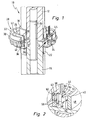
- FIG. 1 shows a generally designated 10 steering shaft of a motor vehicle, of which two shaft sections 12 and 14 can be seen.
- the two shaft sections 12 and 14 are connected to each other via a torsion bar spring 16, so that their free, mutually facing ends 18 and 20 are then rotated relative to each other when a torque on the steering shaft 10 is applied.
- a magnetic ring holder 22 is attached, which carries a generally designated 24 Mulipol magnetic ring.
- This magnetic ring 24 surrounds the steering shaft 10 at a radial distance, so that between the magnetic ring 24 and the steering shaft 10, a stator 26 can engage.
- This stator element 26 is part of a generally designated 28 stator, which is attached to a stator 30.
- This stator holder 30 is in turn attached to the free end 20 of the shaft portion 12.
- the first stator element 26 is radially opposed to a second stator element 32 and, like the first stator element 26, is held by the stator holder 30 and securely positioned. From both stator elements 26 and 32 protrude downwards fingers 34 and 36, which receive the magnetic ring 24 between them.
- the two stator elements 26 and 32 are made of soft magnetic material.
- FIG. 1 It can be seen that the free upper ends 38 and 40 of the two stator elements 26 and 32 form a gap 42. In this gap 42, a magnetic field sensor 44 is disposed, and is the two ends 38 and 40 directly opposite, which is made FIG. 2 is clearly visible.
- the fingers 34 and 36 each protrude from a magnetic flux ring 46 and 48, which in the fingers 34 and 36 merge each induced magnetic flux and conduct in the direction of the magnetic field sensor 44.
- a first magnetic flux concentrator 56 which lies between the magnetic field sensor 44 and the magnetic flux ring 46, is arranged on the magnetic field sensor 44.
- a second magnetic flux concentrator 58 is arranged between the magnetic field sensor 44 and the magnetic flux ring 48.
- the two magnetic flux concentrators 56 and 58 each have a portion 60 and 62 which are adjacent to the magnetic flux rings 46 and 48.
- a respective section 64 which is adjacent to the magnetic field sensor 44. Sections 60 and 62 merge into section 64 via an offset.
- the central portion 64 is not bent, but the magnetic flux ring 46 and 48 facing portions 60 and 62 are formed continuously, and only on the magnetic field sensor 44 side facing is then a bump, the Section 64 forms. Adjacent to sections 60 and 62 is a small air gap 42 which separates them from the magnetic flux rings 46 and 48, which is clearly the second embodiment in FIG FIG. 7 is shown.
- the two magnetic flux concentrators 56 and 58 and the magnetic field sensor 44 are in one arranged common housing and can be inserted in the axial direction between the two magnetic flux rings 46 and 48 in the stator 28.
- FIGS. 3a and 3b the position of the individual fingers 34 and 36 with respect to the poles 50 and 52 of the magnetic ring 24 can be removed.
- the fingers 34 and 36 are radially opposed to each other.
- FIG. 3a In the FIG. 3a is applied to the steering shaft 10 no torque, so that the FIG. 3a indicates the rest or neutral state. It can clearly be seen that the fingers 34 and 36 are opposite to the transitions 54 between the poles 50 and 52, respectively. For reasons of symmetry, the stator elements 26 and 32 remain magnetically neutral overall; that is, in the air gap 42, therefore, no magnetic field is formed.
- FIG. 3b If a torque is exerted on the steering shaft 10, then the two ends 18 and 20 of the two shaft sections 12 and 14 rotate relative to one another, which results in FIG. 3b is shown.
- the fingers 34 and 36 are now one of the poles 50 and 52 opposite (in the FIG. 3b the pole 50).
- the radially inner fingers 34 are, for example, the north poles and the radially outer fingers 36 facing the south poles.
- the inner stator element 26 becomes too a north pole and the outer stator element 32 magnetized to a south pole.
- the magnetic field sensor 44 which is stationary on eg in FIG.
- housing 68 of the steering shaft 10 is immersed with its sensitive surface in this gap 42 and measures over the Magent Wegkonzentratoren 56 and 58, the strength of the magnetic induction, which is a direct measure of the magnitude of the torque.
- the strength of the magnetic induction is constant at constant torque also over the entire circumference of the gap 42. This means that the steering shaft 10 with the magnetic ring 24 and the stator 28 can be rotated freely.
- the sensor 44 operates completely contactless.
- the pole pitch of the magnetic ring 24 can be chosen to be relatively fine, so that the linearity range coincides almost with the angular ranges to be measured. This results in the same torque compared with the prior art, a larger output signal, which is synonymous with a better signal / noise ratio. Since the magnetic ring is made of a plastic-bonded magnetic material, it can be made cheaper and more accurate. Due to the large distance of the fingers 34 and 36 in relation to the air gap 42, no competing shunt exists and the magnetic field lines concentrate optimally on the magenta flux concentrators 56 and 58. In this way, the output signal is also increased.
- the magnetic field sensor 44 Since the magnetic field sensor 44 is arranged in the axial direction in the gap 42, the assembly is facilitated since the magnetic field sensor 44 can be attached directly to a holder which is pushed onto the shaft 10 in the axial direction and is centered by this. This results in low mounting tolerances.
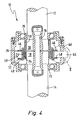
- FIG. 4 shows a longitudinal section through a second embodiment of the invention, wherein identical or equivalent components are designated by the same reference numerals.
- the stator 28 At the end 18 of the shaft portion 14 of the magnetic ring 24 is fixed, which is surrounded by the stator 28.
- This stator 28 is in turn attached via the stator holder 30 at the end 20 of the shaft portion 12.
- the structure of the stator 28 substantially corresponds to that as in the FR 2,821,668 A1 is described, so that the stator 28 has two stator elements 26 and 32.
- These stator elements 26 and 32 are angled substantially L-shaped, wherein the one L-leg of the magnetic flux ring 46 and 48 and the other L-leg of the fingers 34 and 36 are formed.
- the fingers 34 and 36 are for example in the FIGS. 6 and 8th shown.
- the magnetic field sensor 44 disposed, which in turn is housed in the sensor housing 66.
- the two magnetic flux concentrators 56 and 58 which abut with its section 64 directly to the magnetic field sensor 44.
- FIG. 6 shows the magnetic flux concentrator 56 in longitudinal section and it can be seen that the section 64 merges into the two sections 60 and 62. Overall, the magnetic flux concentrator 56 is bent and follows the curvature of the magnetic flux ring 46. In addition, it can be seen that the two portions 60 and 62 substantially overlap two fingers 36 of the magnetic flux ring 46, thereby concentrating the magnetic flux induced in these two fingers 36 and the magnetic field sensor 44 is supplied.
- the flux concentrator 56 or 58 can also be made straight.
- the length is not the number of covered fingers 34 and 36 correlated.
- the flow collected by the fingers 34 and 36 is distributed circumferentially by the magnetic flux rings 46 and 48 and the flux concentrators 56 and 58 selectively return the flow via the magnetic field sensor 44.
- the design of the two magnetic flux concentrators 56 and 58 is clear from the FIG. 7 in particular, the course of the sections 60, 62 and 64, and it can be clearly seen that the sections 64 abut the magnetic field sensor 44 and the sections 60 and 62 are immediately adjacent the magnetic flux rings 46 and 48, wherein between the sections 60 and 62 and the magnetic flux rings 46 and 48, only a small air gap 42 prevails.
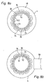
- FIG. 8a is like in the FIG. 3a , The neutral position shown in which no torque is applied to the steering shaft 10.
- the individual fingers 34 and 36 are exactly in the middle of the respective transitions 54 between the poles 50 and 52 opposite.
- the stator elements 26 and 32 and thus also the magnetic flux rings 46 and 48 remain magnetically neutral. That is, in the air gap 42 no magnetic field is formed.
- FIG. 8b a torque is applied to the steering shaft 10, so that the magnetic ring 24 and the stator 28 rotate relative to each other.
- the fingers 34 and 36 are now opposite the south poles 50 and the north poles 52, respectively.
- a magnetic flux is now induced, which is transmitted via the magnetic flux rings 46 and 48 and the magnetic flux concentrators 56 and 58 to the magnetic field sensor 44.
- the same advantages are achieved as in the first embodiment.
- the assembly of the magnetic field sensor 44 together with its sensor housing 66 takes place in the radial direction, which is made FIG. 4 is apparent.
- This sensor housing 66 is fixed by a housing 68, wherein the steering shaft 10 is decoupled via pivot bearing 70 from the housing 68.
- the magnetic field sensor 44 is arranged protected and easy to install, due to the magnetic flux concentrators 56 and 58, the signal has no ripple.
- the signal generated by the magnetic field sensor 44 directly corresponds to the applied torque.
Landscapes
- Physics & Mathematics (AREA)
- Electromagnetism (AREA)
- General Physics & Mathematics (AREA)
- Power Steering Mechanism (AREA)
- Control Of Transmission Device (AREA)
- Testing Of Devices, Machine Parts, Or Other Structures Thereof (AREA)
- Force Measurement Appropriate To Specific Purposes (AREA)
Abstract
Description
Die Erfindung betrifft eine Vorrichtung zum Bestimmen eines auf eine Welle ausgeübten Drehmoments mit den Merkmalen des Oberbegriffs des Anspruchs 1.The invention relates to a device for determining a torque exerted on a shaft having the features of the preamble of claim 1.
Aus der
Aus der
Aus der
Aus der
Die Polteilung muss durch diskreten Aufbau des Magnetrades relativ grob gewählt werden (Polbreite 20°), was einen ebenso großen Linearitätsbereich bewirkt, der aber nicht vollständig ausgenutzt wird, da der Bereich des zu messenden Winkels aufgrund der geforderten Steifigkeiten des Torsionssystem nur etwa ± 3° bis 5° beträgt. Der Magnetfluss kann nicht optimal ausgenutzt werden, da der den magnetischen Rückschluss bildende Luftspalt über den gesamten Umfang gleich ausgebildet ist, so dass sich der Magnetfluss auf eine große Fläche verteilt und deshalb am Ort des Magnetfeldsensors nur relativ gering ist.The pole pitch must be chosen relatively coarse by discrete structure of the magnetic wheel (
Ausgehend von der
Diese Aufgabe wird erfindungsgemäß mit einer Vorrichtung gelöst, die die Merkmale des Anspruchs 1 aufweist.This object is achieved with a device having the features of claim 1.
Die Anordnung des Magnetflusskonzentrators hat den wesentlichen Vorteil, dass der Magnetfeldsensor geschützt angeordnet ist. Durch den Magnetflusskonzentrator wird ein wesentlich stärkeres Signal empfangen, welches als direktes Maß für das Drehmoment verwendet werden kann, ohne dass dieses noch aufwendig ausgewertet werden müsste. Ein weiterer Vorteil besteht darin, dass der erfindungsgemäße Aufbau unempfindlich gegenüber mechanischen Toleranzen ist, da der Magnetflusskonzentrator innerhalb des Stators sich befindet.The arrangement of the magnetic flux concentrator has the significant advantage that the magnetic field sensor is arranged protected. By the magnetic flux concentrator a much stronger signal is received, which can be used as a direct measure of the torque, without this would have to be evaluated consuming. A further advantage is that the construction according to the invention is insensitive to mechanical tolerances, since the magnetic flux concentrator is located inside the stator.
Zwischen dem Magnetfeldsensor und jedem Magnetflussring ist also ein Magnetflusskonzentrator angeordnet ist. Dies bedeutet, dass der Magnetfluss zwischen dem Magnetflussring und dem Magnetfeldsensor stets über einen Magnetflusskonzentrator läuft.Thus, a magnetic flux concentrator is arranged between the magnetic field sensor and each magnetic flux ring. This means that the magnetic flux between the magnetic flux ring and the magnetic field sensor always runs over a magnetic flux concentrator.
Dabei weist der Magnetflusskonzentrator einen dem Magnetflussring benachbarten und einen dem Magnetfeldsensor benachbarten Abschnitt auf. Auf diese Weise kann sich der Magnetflusskonzentrator sowohl bis in die unmittelbare Nähe des Magnetflussringes als auch bis in die unmittelbare Nähe des Magnetfeldsensors erstrecken.In this case, the magnetic flux concentrator has a section adjacent to the magnetic flux ring and a section adjacent to the magnetic field sensor. In this way, the magnetic flux concentrator can extend both into the immediate vicinity of the magnetic flux ring and into the immediate vicinity of the magnetic field sensor.
Weiterhin sind dabei die Abschnitte in zueinander versetzten Ebenen oder Flächen angeordnet. Auf diese Weise wird der Magnetfluss optimal von den Magnetflussringen in Richtung des Magnetfeldsensors gelenkt und geleitet. Dabei sind die beiden Abschnitte über eine Abkröpfung miteinander verbunden.Furthermore, the sections are arranged in mutually offset planes or surfaces. In this way, the magnetic flux is optimally directed and guided by the magnetic flux rings in the direction of the magnetic field sensor. The two sections are connected to each other via a bend.
Um eine optimale Verstärkung des Signals zu erhalten, erstreckt sich der Magnetflusskonzentrator benachbart zum Magnetflussring über einen Abschnitt in dessen Umfangsrichtung. Dabei ist der Magnetflusskonzentrator vorteilhaft der Krümmung des Magnetflussringes angepasst. Um den Widerstand im den Rückschluss bildenden Luftspalt so gering wie möglich zu halten, ist zwischen dem Magnetflusskonzentrator und dem Magnetflussring ein sehr enger Luftspalt vorhanden. Dabei ist von Vorteil, dass der Magnetfeldsensor berührungslos arbeitet und dennoch einen geringen Widerstand im Rückschluss besitzt.In order to obtain an optimum amplification of the signal, the magnetic flux concentrator extends adjacent to the magnetic flux ring over a portion in its circumferential direction. The magnetic flux concentrator is advantageously adapted to the curvature of the magnetic flux ring. In order to keep the resistance in the trailing air gap as small as possible, a very narrow air gap exists between the magnetic flux concentrator and the magnetic flux ring. It is advantageous that the magnetic field sensor operates without contact and yet has a low resistance in the conclusion.
Bei einem Ausführungsbeispiel verläuft der Luftspalt in einer in Umfangsrichtung sich erstreckenden Fläche. Bei einem anderen Ausführungsbeispiel verläuft der Luftspalt in einer in radialer Richtung sich erstreckenden Fläche, das heißt in einer Radialebene. Im ersteren Fall ist der Magnetfeldsensor axial und im zweiten Ausführungsbeispiel radial in den Stator eingesetzt.In one embodiment, the air gap extends in a circumferentially extending surface. In another embodiment, the air gap extends in a radially extending surface, that is, in a radial plane. In the former case is the Magnetic field sensor used axially and in the second embodiment radially in the stator.
Um eine optimale Ausnutzung des gesamten Feldes, und zwar hinsichtlich der Feldstärke, des Winkelmessbereichs, der Polzahl und so weiter zu erhalten, ist der den Magnetflussring benachbarte Abschnitt breiter als die Breite eines Fingers, insbesondere ist dieser doppelt so breit. Für eine Redundanz sind mindestens zwei unabhängige Magnetfeldsensoren vorgesehen. Die Flusskonzentratoren haben dann zwei Abkröpfungen. Der Flusskonzentrator ist in einer bestimmten Länge ausgeführt, um eine größere Empfindlichkeit zu erhalten und um eine eventuelle Signalwelligkeit auszumitteln.In order to obtain an optimum utilization of the entire field, namely with respect to the field strength, the angle measuring range, the number of poles and so on, the portion adjacent to the magnetic flux ring is wider than the width of a finger, in particular it is twice as wide. For redundancy, at least two independent magnetic field sensors are provided. The flux concentrators then have two offsets. The flux concentrator is designed in a certain length to obtain greater sensitivity and to average out any signal ripple.
Eine einfache Montage und exakte Zuordnung zueinander wird dadurch erzielt, dass der beziehungsweise die Magnetflusskonzentrator(en) und der Magnetfeldsensor in einem gemeinsamen Halter und/oder Sensorgehäuse angeordnet sind. Über diesen Halter werden sowohl der Magnetfeldsensor als auch die Magnetflusskonzentratoren zueinander positioniert und innerhalb des Stators fixiert und zudem gegen Umwelteinflüsse geschützt.A simple assembly and exact assignment to each other is achieved in that the or the magnetic flux concentrator (s) and the magnetic field sensor are arranged in a common holder and / or sensor housing. About this holder, both the magnetic field sensor as well as the magnetic flux concentrators positioned to each other and fixed within the stator and also protected against environmental influences.
Weitere Vorteile, Merkmale und Einzelheiten der Erfindung ergeben sich aus den Unteransprüchen sowie der nachfolgenden Beschreibung, in der unter Bezugnahme auf die Zeichnung zwei besonders bevorzugte Ausführungsbeispiele im einzelnen beschrieben sind. Dabei können die in der Zeichnung dargestellten als auch in den Ansprüchen und in der Beschreibung erwähnten Merkmale jeweils einzeln für sich oder in beliebiger Kombination erfindungswesentlich sein.Further advantages, features and details of the invention will become apparent from the subclaims and the following description in which two particularly preferred embodiments are described in detail with reference to the drawing. The features mentioned in the drawing as well as in the claims and in the description mentioned features may each be essential to the invention individually or in any desired combination.
In der Zeichnung zeigen:
- Figur 1
- eine perspektivische Darstellung des erfindungsgemäßen, an einer Welle angeordneten Drehmomentsensors, teilweise geschnitten;
- Figur 2
- eine Schnittansicht in Richtung des Pfeils II gemäß
Figur 1 ; - Figur 3
- eine schematische Darstellung der Relativpositionen von Magnetring und Stator ohne an der Welle wirkendem Drehmoment (
Figur 3a ) und bei aufgebrachtem Drehmoment (Figur 3b ); - Figur 4
- einen Längsschnitt durch eine zweite Ausführungsform des erfindungsgemäßen Drehmomentsensors;
- Figur 5
- eine vergrößerte Wiedergabe des Ausschnitts V gemäß
Figur 4 ; - Figur 6
- einen Schnitt VI-VI gemäß
Figur 5 ; - Figur 7
- einen Schnitt VII-VII gemäß
Figur 5 ; und - Figur 8
- eine schematische Darstellung der Relativpositionen von Magnetring und Stator ohne an der Welle wirkendem Drehmoment (
Figur 8a ) und bei aufgebrachtem Drehmoment (Figur 8b ).
- FIG. 1
- a perspective view of the invention, arranged on a shaft torque sensor, partially cut;
- FIG. 2
- a sectional view in the direction of the arrow II according to
FIG. 1 ; - FIG. 3
- a schematic representation of the relative positions of magnetic ring and stator without Torque acting on the shaft (
FIG. 3a ) and with applied torque (FIG. 3b ); - FIG. 4
- a longitudinal section through a second embodiment of the torque sensor according to the invention;
- FIG. 5
- an enlarged view of the section V according to
FIG. 4 ; - FIG. 6
- a section VI-VI according to
FIG. 5 ; - FIG. 7
- a section VII-VII according to
FIG. 5 ; and - FIG. 8
- a schematic representation of the relative positions of magnet ring and stator without acting on the shaft torque (
FIG. 8a ) and with applied torque (FIG. 8b ).
Die
Dieses Statorelement 26 ist Teil eines insgesamt mit 28 bezeichneten Stators, der an einem Statorhalter 30 befestigt ist. Dieser Statorhalter 30 ist wiederum am freien Ende 20 des Wellenabschnitts 12 angebracht. Dem ersten Statorelement 26 liegt ein zweites Statorelement 32 radial gegenüber und wird, wie das erste Statorelement 26, vom Statorhalter 30 gehalten und sicher positioniert. Von beiden Statorelementen 26 und 32 ragen nach unten Finger 34 und 36 ab, die zwischen sich den Magnetring 24 aufnehmen. Die beiden Statorelemente 26 und 32 sind aus weichmagnetischem Material gefertigt.This
Ferner ist in der
Aus der
Den
In der
Wird auf die Lenkwelle 10 ein Drehmoment ausgeübt, dann verdrehen sich die beiden Enden 18 und 20 der beiden Wellenabschnitte 12 und 14 gegeneinander, was in
Bei negativem Drehmoment ändert sich die Richtung der relativen Verdrehung, so dass die Finger 34 den Polen 52 gegenüberliegen. Dadurch vertauschen sich die Polaritäten in den Statorelementen 26 und 32.With negative torque, the direction of the relative rotation changes so that the
Von Vorteil ist, dass die Polteilung des Magnetringes 24 relativ fein gewählt werden kann, so dass der Linearitätsbereich sich nahezu mit dem zu messenden Winkelbereichen deckt. Es ergibt sich dadurch bei gleichem Drehmoment, verglichen mit dem Stand der Technik, ein größeres Ausgangssignal, was gleichbedeutend mit einem besseren Signal/Rauschverhältnis ist. Da der Magnetring aus einem kunststoffgebundenen Magnetmaterial hergestellt ist, kann dieser preisgünstiger und genauer gefertigt werden. Durch den im Verhältnis zum Luftspalt 42 großen Abstand der Finger 34 und 36 ist kein konkurrierender Nebenschluss vorhanden und die Magnetfeldlinien konzentrieren sich optimal auf die Magentflusskonzentratoren 56 und 58. Hierdurch wird das Ausgangssignal ebenfalls vergrößert. Da der Magnetfeldsensor 44 in axialer Richtung im Spalt 42 angeordnet ist, wird die Montage erleichtert, da der Magnetfeldsensor 44 direkt an einem Halter befestigt werden kann, welcher in axialer Richtung auf die Welle 10 aufgeschoben wird und von dieser zentriert wird. Dadurch entstehen geringe Montagetoleranzen.It is advantageous that the pole pitch of the
Die
Zwischen den beiden Magnetflussringen 46 und 48 ist, wie deutlich in
Die
Der Flusskonzentrator 56 bzw. 58 kann auch gerade ausgeführt werden. Die Länge ist nicht mit der Zahl der überdeckten Finger 34 bzw. 36 korreliert. Der von den Fingern 34 und 36 gesammelte Fluss wird durch die Magnetflussringe 46 und 48 über den Umfang verteilt und die Flusskonzentratoren 56 und 58 leiten den Fluss gezielt über den Magnetfeldsensor 44 zurück.The
Die Ausgestaltung der beiden Magnetflusskonzentratoren 56 und 58 ist deutlich aus der
In der
In der
Auch bei dieser Ausführungsform ist der Magnetfeldsensor 44 geschützt angeordnet und einfach montierbar, wobei aufgrund der Magnetflusskonzentratoren 56 und 58 das Signal keine Welligkeit aufweist. Das vom Magnetfeldsensor 44 erzeugte Signal entspricht direkt dem aufgebrachten Drehmoment.Also in this embodiment, the
Claims (10)
- An apparatus for determining the torque applied to a shaft (10), wherein the shaft (10) has a first shaft section (14) and a second shaft section (12), and the two shaft sections (12 and 14) can be rotated in relation to each other, having a multi- pole magnetic ring (24), which encloses and is connected with the first shaft section (14), and a stator holder (30) fastened on the second shaft section (12), wherein two stator elements (26, 32) are fastened on the stator holder (30) and each stator element (26, 32) has fingers (34, 36), which project away in the axial direction and are arranged, evenly distributed, over at least a portion of the circumference and have gaps between them, wherein the fingers (34, 36) of each stator element (26, 32) are connected with each other via a magnetic flux ring (46, 48), the magnetic flux rings (46, 48) are spaced apart from each other, and a magnetic field sensor (44) is arranged between the magnetic flux rings (46, 48), and wherein two magnetic flux concentrators (56, 58) are assigned to the magnetic field sensor (44), characterized in that the magnetic flux concentrators (56, 58) are provided between the magnetic flux rings (46, 48) and are arranged on the magnetic field sensor (44), wherein the magnetic flux concentrators (56, 58) respectively have a section (60, 62), which adjoins the magnetic flux rings (46, 48), and a section (64) is respectively located between the two sections (60, 62) which adjoins the magnetic field sensor (44), and the sections (60, 62) adjoining the magnetic flux ring (46, 48) are wider than the width of a finger (34, 36) and are arranged in planes or on surfaces which are offset in respect to each other.
- The apparatus in accordance with claim 1, characterized in that, next to the magnetic flux ring (46, 48), the magnetic flux concentrator (56, 58) extends over a section of the circumference of the latter.
- The apparatus in accordance with one of the preceding claims, characterized in that the magnetic flux concentrator (56, 58) is matched to the curvature of the magnetic flux ring (46, 48).
- The apparatus in accordance with one of the preceding claims, characterized in that an air gap (42) is provided between the magnetic flux concentrator (56, 58) and the magnetic flux ring (46, 48).
- The apparatus in accordance with claim 4, characterized in that the air gap (42) extends in a surface which extends in the circumferential direction.
- The apparatus in accordance with claim 4, characterized in that the air gap (42) extends in a surface (radial plane) which extends in the radial direction.
- The apparatus in accordance with one of the preceding claims, characterized in that the sections (60, 62, 64) make a transition into each other via a right-angled bend.
- The apparatus in accordance with one of the preceding claims, characterized in that the sections (60, 62) adjoining the magnetic flux ring (46, 48) are twice as wide as the width of a finger (34, 36).
- The apparatus in accordance with one of the preceding claims, characterized in that the magnetic flux concentrator(s) (56, 58) and the magnetic field sensor (44) is/are arranged in a common holder (68) and/or sensor housing (66).
- The apparatus in accordance with one of the preceding claims, characterized in that the magnetic flux generator (56, 58) extends at least over a surface which corresponds to the width of two adjoining fingers (34, 36) of a stator element (26, 32).
Applications Claiming Priority (2)
| Application Number | Priority Date | Filing Date | Title |
|---|---|---|---|
| DE10256321A DE10256321A1 (en) | 2002-11-28 | 2002-11-28 | Device for determining a torque exerted on a shaft |
| DE10256321 | 2002-11-28 |
Publications (2)
| Publication Number | Publication Date |
|---|---|
| EP1424544A1 EP1424544A1 (en) | 2004-06-02 |
| EP1424544B1 true EP1424544B1 (en) | 2009-05-27 |
Family
ID=32240558
Family Applications (1)
| Application Number | Title | Priority Date | Filing Date |
|---|---|---|---|
| EP03025999A Expired - Lifetime EP1424544B1 (en) | 2002-11-28 | 2003-11-14 | Apparatus to detect a torque acting on a shaft |
Country Status (3)
| Country | Link |
|---|---|
| EP (1) | EP1424544B1 (en) |
| AT (1) | ATE432460T1 (en) |
| DE (2) | DE10256321A1 (en) |
Families Citing this family (7)
| Publication number | Priority date | Publication date | Assignee | Title |
|---|---|---|---|---|
| JP4812303B2 (en) * | 2005-01-20 | 2011-11-09 | 株式会社ジェイテクト | Torque detection device |
| US7832287B2 (en) * | 2007-05-04 | 2010-11-16 | Gm Global Technology Operations, Inc. | Sensor gap balancer |
| DE102007028483A1 (en) * | 2007-06-21 | 2008-12-24 | Robert Bosch Gmbh | sensor arrangement |
| DE102009010188A1 (en) * | 2009-02-23 | 2010-08-26 | Dr. Ing. H.C. F. Porsche Aktiengesellschaft | Force/torque sensor for use between steering shaft and steering wheel of steering system of vehicle, has screw hollow cylindrically formed and passed into sensor through electrical inlet |
| DE102010043559A1 (en) | 2010-11-08 | 2012-05-10 | Robert Bosch Gmbh | Sensor arrangement for detecting a torque |
| DE102018119807A1 (en) | 2018-08-15 | 2020-02-20 | Valeo Schalter Und Sensoren Gmbh | Torque sensor device, method for determining a torque, stator and stator arrangement |
| CN111702603B (en) * | 2019-09-30 | 2021-06-29 | 福建恒杰塑业新材料有限公司 | Pipe fitting inner wall polisher |
Family Cites Families (8)
| Publication number | Priority date | Publication date | Assignee | Title |
|---|---|---|---|---|
| US4784002A (en) * | 1986-12-17 | 1988-11-15 | Atsugi Motor Parts Company, Limited | Torque sensor |
| US4724710A (en) * | 1986-12-22 | 1988-02-16 | General Motors Corporation | Electromagnetic torque sensor for a rotary shaft |
| FR2688060B1 (en) * | 1992-02-28 | 1994-04-15 | Snr Roulements | MAGNET STRUCTURE FOR DISPLACEMENT SENSOR. |
| US5757181A (en) | 1992-06-22 | 1998-05-26 | Durakool Incorporated | Electronic circuit for automatically compensating for errors in a sensor with an analog output signal |
| JP3491596B2 (en) * | 1999-06-28 | 2004-01-26 | 株式会社デンソー | Rotation angle detector |
| FR2821668B1 (en) * | 2001-03-02 | 2003-05-02 | Moving Magnet Tech | POSITION SENSOR, PARTICULARLY FOR DETECTING THE TORSION OF A STEERING COLUMN |
| FR2824910B1 (en) * | 2001-05-18 | 2005-05-13 | Denso Corp | TORQUE SENSOR AND POWER ASSISTED STEERING SYSTEM EMPLOYING THIS SENSOR |
| US6701792B2 (en) * | 2001-08-27 | 2004-03-09 | Visteon Global Technologies, Inc. | Torque sensing apparatus for measuring relative torque between two shafts |
-
2002
- 2002-11-28 DE DE10256321A patent/DE10256321A1/en not_active Withdrawn
-
2003
- 2003-11-14 DE DE50311547T patent/DE50311547D1/en not_active Expired - Lifetime
- 2003-11-14 EP EP03025999A patent/EP1424544B1/en not_active Expired - Lifetime
- 2003-11-14 AT AT03025999T patent/ATE432460T1/en not_active IP Right Cessation
Also Published As
| Publication number | Publication date |
|---|---|
| DE50311547D1 (en) | 2009-07-09 |
| ATE432460T1 (en) | 2009-06-15 |
| EP1424544A1 (en) | 2004-06-02 |
| DE10256321A1 (en) | 2004-06-09 |
Similar Documents
| Publication | Publication Date | Title |
|---|---|---|
| DE60200499T3 (en) | Position sensor, especially for detecting the rotation of a steering column | |
| EP2743662B1 (en) | Device with a torque sensor device and optionally a steering angle sensor apparatus for a motor vehicle | |
| EP2932217B1 (en) | Device with a torque sensor arrangement and a steering angle sensor arrangement for a motor vehicle, and motor vehicle | |
| EP1464935B1 (en) | Apparatus for determining the torque applied to a shaft | |
| EP1424541B1 (en) | Apparatus for determining the torque applied to a shaft | |
| DE102005018286A1 (en) | Torque determining device e.g. torque sensor, for use on steering shaft of motor vehicle, has stator units having fingers connected with each other by rings, and three magnetic field sensors exposed to same magnetic field | |
| WO2007079993A1 (en) | Rotor and an electrical machine comprising such a rotor | |
| EP0920605B1 (en) | Magnetic position sensor | |
| DE3732958C2 (en) | ||
| DE10310567A1 (en) | Bearing assembly with rotation sensor that is able to detect the zero position | |
| EP0920113B1 (en) | Dc motor | |
| EP1424544B1 (en) | Apparatus to detect a torque acting on a shaft | |
| EP0998658B1 (en) | Magnetic position sensor | |
| DE19581628C2 (en) | Position sensor for engine shaft formed with complementary targets | |
| EP3708988B1 (en) | Torque sensor and drive unit for a bicycle | |
| DE20305732U1 (en) | Device for determining torque applied to a shaft has a multi-pole magnetic ring, stator elements, magnetic flux rings and a magnetic field sensor | |
| EP0425529A1 (en) | A measuring device for determining an angle of rotation. | |
| DE19731555B4 (en) | Magnetic position sensor | |
| DE4103561C2 (en) | Rotary position encoder for the detection of a rotor position | |
| DE20220388U1 (en) | Device for measurement of the torque applied to a shaft, e.g. a motor vehicle steering wheel shaft, has a flux concentrator that enables a magnetic field sensor to be securely positioned so that it is insensitive to tolerances | |
| DE102015104888B4 (en) | Arrangement of a magnetic element with position sensor for position detection on a rotatable machine element | |
| WO2004034555A1 (en) | Sensor assembly for detecting a rotation-related variable of an electronic motor | |
| DE10008539C2 (en) | Measuring device for non-contact detection of a rotation angle or a torque | |
| DE20220383U1 (en) | Device for measurement of the torque applied to a shaft, e.g. for determining the torque applied to a motor vehicle steering wheel shaft, has a stator arrangement with inner and outer fingers for increasing measurement sensitivity | |
| DE102021129981A1 (en) | Sensor device with a torque sensor device and a steering angle sensor device for a motor vehicle |
Legal Events
| Date | Code | Title | Description |
|---|---|---|---|
| PUAI | Public reference made under article 153(3) epc to a published international application that has entered the european phase |
Free format text: ORIGINAL CODE: 0009012 |
|
| AK | Designated contracting states |
Kind code of ref document: A1 Designated state(s): AT BE BG CH CY CZ DE DK EE ES FI FR GB GR HU IE IT LI LU MC NL PT RO SE SI SK TR |
|
| AX | Request for extension of the european patent |
Extension state: AL LT LV MK |
|
| 17P | Request for examination filed |
Effective date: 20041105 |
|
| AKX | Designation fees paid |
Designated state(s): AT BE BG CH CY CZ DE DK EE ES FI FR GB GR HU IE IT LI LU MC NL PT RO SE SI SK TR |
|
| 17Q | First examination report despatched |
Effective date: 20061228 |
|
| GRAP | Despatch of communication of intention to grant a patent |
Free format text: ORIGINAL CODE: EPIDOSNIGR1 |
|
| GRAS | Grant fee paid |
Free format text: ORIGINAL CODE: EPIDOSNIGR3 |
|
| GRAA | (expected) grant |
Free format text: ORIGINAL CODE: 0009210 |
|
| AK | Designated contracting states |
Kind code of ref document: B1 Designated state(s): AT BE BG CH CY CZ DE DK EE ES FI FR GB GR HU IE IT LI LU MC NL PT RO SE SI SK TR |
|
| REG | Reference to a national code |
Ref country code: GB Ref legal event code: FG4D Free format text: NOT ENGLISH |
|
| REG | Reference to a national code |
Ref country code: CH Ref legal event code: EP |
|
| REG | Reference to a national code |
Ref country code: IE Ref legal event code: FG4D Free format text: LANGUAGE OF EP DOCUMENT: GERMAN |
|
| REF | Corresponds to: |
Ref document number: 50311547 Country of ref document: DE Date of ref document: 20090709 Kind code of ref document: P |
|
| PG25 | Lapsed in a contracting state [announced via postgrant information from national office to epo] |
Ref country code: PT Free format text: LAPSE BECAUSE OF FAILURE TO SUBMIT A TRANSLATION OF THE DESCRIPTION OR TO PAY THE FEE WITHIN THE PRESCRIBED TIME-LIMIT Effective date: 20090927 Ref country code: FI Free format text: LAPSE BECAUSE OF FAILURE TO SUBMIT A TRANSLATION OF THE DESCRIPTION OR TO PAY THE FEE WITHIN THE PRESCRIBED TIME-LIMIT Effective date: 20090527 |
|
| NLV1 | Nl: lapsed or annulled due to failure to fulfill the requirements of art. 29p and 29m of the patents act | ||
| PG25 | Lapsed in a contracting state [announced via postgrant information from national office to epo] |
Ref country code: SI Free format text: LAPSE BECAUSE OF FAILURE TO SUBMIT A TRANSLATION OF THE DESCRIPTION OR TO PAY THE FEE WITHIN THE PRESCRIBED TIME-LIMIT Effective date: 20090527 Ref country code: NL Free format text: LAPSE BECAUSE OF FAILURE TO SUBMIT A TRANSLATION OF THE DESCRIPTION OR TO PAY THE FEE WITHIN THE PRESCRIBED TIME-LIMIT Effective date: 20090527 Ref country code: SE Free format text: LAPSE BECAUSE OF FAILURE TO SUBMIT A TRANSLATION OF THE DESCRIPTION OR TO PAY THE FEE WITHIN THE PRESCRIBED TIME-LIMIT Effective date: 20090827 |
|
| REG | Reference to a national code |
Ref country code: IE Ref legal event code: FD4D |
|
| PG25 | Lapsed in a contracting state [announced via postgrant information from national office to epo] |
Ref country code: RO Free format text: LAPSE BECAUSE OF FAILURE TO SUBMIT A TRANSLATION OF THE DESCRIPTION OR TO PAY THE FEE WITHIN THE PRESCRIBED TIME-LIMIT Effective date: 20090527 Ref country code: IE Free format text: LAPSE BECAUSE OF FAILURE TO SUBMIT A TRANSLATION OF THE DESCRIPTION OR TO PAY THE FEE WITHIN THE PRESCRIBED TIME-LIMIT Effective date: 20090527 Ref country code: ES Free format text: LAPSE BECAUSE OF FAILURE TO SUBMIT A TRANSLATION OF THE DESCRIPTION OR TO PAY THE FEE WITHIN THE PRESCRIBED TIME-LIMIT Effective date: 20090907 Ref country code: EE Free format text: LAPSE BECAUSE OF FAILURE TO SUBMIT A TRANSLATION OF THE DESCRIPTION OR TO PAY THE FEE WITHIN THE PRESCRIBED TIME-LIMIT Effective date: 20090527 Ref country code: DK Free format text: LAPSE BECAUSE OF FAILURE TO SUBMIT A TRANSLATION OF THE DESCRIPTION OR TO PAY THE FEE WITHIN THE PRESCRIBED TIME-LIMIT Effective date: 20090527 Ref country code: CZ Free format text: LAPSE BECAUSE OF FAILURE TO SUBMIT A TRANSLATION OF THE DESCRIPTION OR TO PAY THE FEE WITHIN THE PRESCRIBED TIME-LIMIT Effective date: 20090527 |
|
| PG25 | Lapsed in a contracting state [announced via postgrant information from national office to epo] |
Ref country code: SK Free format text: LAPSE BECAUSE OF FAILURE TO SUBMIT A TRANSLATION OF THE DESCRIPTION OR TO PAY THE FEE WITHIN THE PRESCRIBED TIME-LIMIT Effective date: 20090527 |
|
| PG25 | Lapsed in a contracting state [announced via postgrant information from national office to epo] |
Ref country code: BG Free format text: LAPSE BECAUSE OF FAILURE TO SUBMIT A TRANSLATION OF THE DESCRIPTION OR TO PAY THE FEE WITHIN THE PRESCRIBED TIME-LIMIT Effective date: 20090827 |
|
| PLBE | No opposition filed within time limit |
Free format text: ORIGINAL CODE: 0009261 |
|
| STAA | Information on the status of an ep patent application or granted ep patent |
Free format text: STATUS: NO OPPOSITION FILED WITHIN TIME LIMIT |
|
| 26N | No opposition filed |
Effective date: 20100302 |
|
| BERE | Be: lapsed |
Owner name: VALEO SCHALTER UND SENSOREN G.M.B.H. Effective date: 20091130 |
|
| PG25 | Lapsed in a contracting state [announced via postgrant information from national office to epo] |
Ref country code: MC Free format text: LAPSE BECAUSE OF NON-PAYMENT OF DUE FEES Effective date: 20091130 |
|
| REG | Reference to a national code |
Ref country code: CH Ref legal event code: PL |
|
| GBPC | Gb: european patent ceased through non-payment of renewal fee |
Effective date: 20091114 |
|
| PG25 | Lapsed in a contracting state [announced via postgrant information from national office to epo] |
Ref country code: LI Free format text: LAPSE BECAUSE OF NON-PAYMENT OF DUE FEES Effective date: 20091130 Ref country code: BE Free format text: LAPSE BECAUSE OF NON-PAYMENT OF DUE FEES Effective date: 20091130 Ref country code: CH Free format text: LAPSE BECAUSE OF NON-PAYMENT OF DUE FEES Effective date: 20091130 Ref country code: GR Free format text: LAPSE BECAUSE OF FAILURE TO SUBMIT A TRANSLATION OF THE DESCRIPTION OR TO PAY THE FEE WITHIN THE PRESCRIBED TIME-LIMIT Effective date: 20090828 |
|
| PG25 | Lapsed in a contracting state [announced via postgrant information from national office to epo] |
Ref country code: GB Free format text: LAPSE BECAUSE OF NON-PAYMENT OF DUE FEES Effective date: 20091114 |
|
| PG25 | Lapsed in a contracting state [announced via postgrant information from national office to epo] |
Ref country code: AT Free format text: LAPSE BECAUSE OF NON-PAYMENT OF DUE FEES Effective date: 20091114 |
|
| PG25 | Lapsed in a contracting state [announced via postgrant information from national office to epo] |
Ref country code: IT Free format text: LAPSE BECAUSE OF FAILURE TO SUBMIT A TRANSLATION OF THE DESCRIPTION OR TO PAY THE FEE WITHIN THE PRESCRIBED TIME-LIMIT Effective date: 20090527 |
|
| PG25 | Lapsed in a contracting state [announced via postgrant information from national office to epo] |
Ref country code: LU Free format text: LAPSE BECAUSE OF NON-PAYMENT OF DUE FEES Effective date: 20091114 |
|
| PG25 | Lapsed in a contracting state [announced via postgrant information from national office to epo] |
Ref country code: HU Free format text: LAPSE BECAUSE OF FAILURE TO SUBMIT A TRANSLATION OF THE DESCRIPTION OR TO PAY THE FEE WITHIN THE PRESCRIBED TIME-LIMIT Effective date: 20091128 |
|
| PG25 | Lapsed in a contracting state [announced via postgrant information from national office to epo] |
Ref country code: TR Free format text: LAPSE BECAUSE OF FAILURE TO SUBMIT A TRANSLATION OF THE DESCRIPTION OR TO PAY THE FEE WITHIN THE PRESCRIBED TIME-LIMIT Effective date: 20090527 |
|
| PG25 | Lapsed in a contracting state [announced via postgrant information from national office to epo] |
Ref country code: CY Free format text: LAPSE BECAUSE OF FAILURE TO SUBMIT A TRANSLATION OF THE DESCRIPTION OR TO PAY THE FEE WITHIN THE PRESCRIBED TIME-LIMIT Effective date: 20090527 |
|
| REG | Reference to a national code |
Ref country code: FR Ref legal event code: PLFP Year of fee payment: 13 |
|
| REG | Reference to a national code |
Ref country code: FR Ref legal event code: PLFP Year of fee payment: 14 |
|
| REG | Reference to a national code |
Ref country code: FR Ref legal event code: PLFP Year of fee payment: 15 |
|
| PGFP | Annual fee paid to national office [announced via postgrant information from national office to epo] |
Ref country code: FR Payment date: 20221122 Year of fee payment: 20 Ref country code: DE Payment date: 20221114 Year of fee payment: 20 |
|
| P01 | Opt-out of the competence of the unified patent court (upc) registered |
Effective date: 20230528 |
|
| REG | Reference to a national code |
Ref country code: DE Ref legal event code: R071 Ref document number: 50311547 Country of ref document: DE |