EP2932142B1 - Multiple-way mixing valve and method for controlling a multiple-way mixing valve over time - Google Patents
Multiple-way mixing valve and method for controlling a multiple-way mixing valve over time Download PDFInfo
- Publication number
- EP2932142B1 EP2932142B1 EP13815380.4A EP13815380A EP2932142B1 EP 2932142 B1 EP2932142 B1 EP 2932142B1 EP 13815380 A EP13815380 A EP 13815380A EP 2932142 B1 EP2932142 B1 EP 2932142B1
- Authority
- EP
- European Patent Office
- Prior art keywords
- connections
- switching element
- mixing valve
- connection
- switching
- Prior art date
- Legal status (The legal status is an assumption and is not a legal conclusion. Google has not performed a legal analysis and makes no representation as to the accuracy of the status listed.)
- Active
Links
- 238000002156 mixing Methods 0.000 title claims description 54
- 238000000034 method Methods 0.000 title claims description 8
- 238000010438 heat treatment Methods 0.000 claims description 46
- XLYOFNOQVPJJNP-UHFFFAOYSA-N water Substances O XLYOFNOQVPJJNP-UHFFFAOYSA-N 0.000 claims description 16
- 239000011248 coating agent Substances 0.000 claims description 5
- 238000000576 coating method Methods 0.000 claims description 5
- 229920002943 EPDM rubber Polymers 0.000 claims description 4
- 238000002360 preparation method Methods 0.000 claims description 3
- 229920003051 synthetic elastomer Polymers 0.000 claims description 2
- 239000005061 synthetic rubber Substances 0.000 claims description 2
- 230000001960 triggered effect Effects 0.000 claims 2
- 239000012530 fluid Substances 0.000 description 12
- 238000007789 sealing Methods 0.000 description 10
- 238000003860 storage Methods 0.000 description 10
- 238000004891 communication Methods 0.000 description 9
- 229920001343 polytetrafluoroethylene Polymers 0.000 description 3
- 239000004810 polytetrafluoroethylene Substances 0.000 description 3
- 230000005540 biological transmission Effects 0.000 description 2
- 238000011161 development Methods 0.000 description 2
- 230000018109 developmental process Effects 0.000 description 2
- 230000003993 interaction Effects 0.000 description 2
- 239000000203 mixture Substances 0.000 description 2
- 230000008569 process Effects 0.000 description 2
- 238000001179 sorption measurement Methods 0.000 description 2
- 230000000903 blocking effect Effects 0.000 description 1
- 230000008859 change Effects 0.000 description 1
- 230000001419 dependent effect Effects 0.000 description 1
- 238000007667 floating Methods 0.000 description 1
- 238000005338 heat storage Methods 0.000 description 1
- 238000009434 installation Methods 0.000 description 1
- 238000004519 manufacturing process Methods 0.000 description 1
- -1 polytetrafluoroethylene Polymers 0.000 description 1
- 238000003825 pressing Methods 0.000 description 1
- 238000000926 separation method Methods 0.000 description 1
- 230000007704 transition Effects 0.000 description 1
Images


Classifications
-
- F—MECHANICAL ENGINEERING; LIGHTING; HEATING; WEAPONS; BLASTING
- F16—ENGINEERING ELEMENTS AND UNITS; GENERAL MEASURES FOR PRODUCING AND MAINTAINING EFFECTIVE FUNCTIONING OF MACHINES OR INSTALLATIONS; THERMAL INSULATION IN GENERAL
- F16K—VALVES; TAPS; COCKS; ACTUATING-FLOATS; DEVICES FOR VENTING OR AERATING
- F16K11/00—Multiple-way valves, e.g. mixing valves; Pipe fittings incorporating such valves
- F16K11/02—Multiple-way valves, e.g. mixing valves; Pipe fittings incorporating such valves with all movable sealing faces moving as one unit
- F16K11/06—Multiple-way valves, e.g. mixing valves; Pipe fittings incorporating such valves with all movable sealing faces moving as one unit comprising only sliding valves, i.e. sliding closure elements
- F16K11/072—Multiple-way valves, e.g. mixing valves; Pipe fittings incorporating such valves with all movable sealing faces moving as one unit comprising only sliding valves, i.e. sliding closure elements with pivoted closure members
- F16K11/076—Multiple-way valves, e.g. mixing valves; Pipe fittings incorporating such valves with all movable sealing faces moving as one unit comprising only sliding valves, i.e. sliding closure elements with pivoted closure members with sealing faces shaped as surfaces of solids of revolution
-
- F—MECHANICAL ENGINEERING; LIGHTING; HEATING; WEAPONS; BLASTING
- F16—ENGINEERING ELEMENTS AND UNITS; GENERAL MEASURES FOR PRODUCING AND MAINTAINING EFFECTIVE FUNCTIONING OF MACHINES OR INSTALLATIONS; THERMAL INSULATION IN GENERAL
- F16K—VALVES; TAPS; COCKS; ACTUATING-FLOATS; DEVICES FOR VENTING OR AERATING
- F16K11/00—Multiple-way valves, e.g. mixing valves; Pipe fittings incorporating such valves
- F16K11/02—Multiple-way valves, e.g. mixing valves; Pipe fittings incorporating such valves with all movable sealing faces moving as one unit
- F16K11/08—Multiple-way valves, e.g. mixing valves; Pipe fittings incorporating such valves with all movable sealing faces moving as one unit comprising only taps or cocks
- F16K11/085—Multiple-way valves, e.g. mixing valves; Pipe fittings incorporating such valves with all movable sealing faces moving as one unit comprising only taps or cocks with cylindrical plug
- F16K11/0856—Multiple-way valves, e.g. mixing valves; Pipe fittings incorporating such valves with all movable sealing faces moving as one unit comprising only taps or cocks with cylindrical plug having all the connecting conduits situated in more than one plane perpendicular to the axis of the plug
-
- F—MECHANICAL ENGINEERING; LIGHTING; HEATING; WEAPONS; BLASTING
- F24—HEATING; RANGES; VENTILATING
- F24D—DOMESTIC- OR SPACE-HEATING SYSTEMS, e.g. CENTRAL HEATING SYSTEMS; DOMESTIC HOT-WATER SUPPLY SYSTEMS; ELEMENTS OR COMPONENTS THEREFOR
- F24D19/00—Details
- F24D19/10—Arrangement or mounting of control or safety devices
- F24D19/1006—Arrangement or mounting of control or safety devices for water heating systems
- F24D19/1009—Arrangement or mounting of control or safety devices for water heating systems for central heating
- F24D19/1015—Arrangement or mounting of control or safety devices for water heating systems for central heating using a valve or valves
-
- F—MECHANICAL ENGINEERING; LIGHTING; HEATING; WEAPONS; BLASTING
- F24—HEATING; RANGES; VENTILATING
- F24D—DOMESTIC- OR SPACE-HEATING SYSTEMS, e.g. CENTRAL HEATING SYSTEMS; DOMESTIC HOT-WATER SUPPLY SYSTEMS; ELEMENTS OR COMPONENTS THEREFOR
- F24D2220/00—Components of central heating installations excluding heat sources
- F24D2220/02—Fluid distribution means
- F24D2220/0242—Multiple way valves
Definitions
- the present invention relates to a multi-way mixing valve according to the preamble of claim 1 and a method for time control according to the preamble of claim 10.
- Multi-way mixing valves are used in many hydraulic circuits and are mainly used in hot water and / or heating systems.
- a multi-way mixing valve in which two drain connections are arranged opposite one another in a circuit plane with respect to the axis of rotation of a switching element and an inlet connection perpendicular to it, parallel to the axis of rotation.
- the switching element has an axial flow channel aligned in the axis of rotation, which communicates with three radial flow channels arranged offset by 120 °, which are arranged in the circuit level of the processes. Due to the special 120 ° arrangement of the radial flow channels, a particularly fast switching of the inlet can be achieved with either one of the two processes.
- a multi-way mixing valve in which a valve housing is used which has a cross shape, with fluid channels being provided in the center of the cross and at all ends of the cross, which can be connected to one another via a switching element arranged in the center of the cross.
- a switching element arranged in the center of the cross.
- two of the fluid channels communicate directly with one another via a bypass and also together with the switching element. This enables simple control of two heat sinks via a single heat source.
- a multi-circuit heating system with two heat sinks, which are connected to a heat source via a mixer manifold, is from the DE 10 2008 013 124 A1 known.
- a four-way valve is used here.
- the U.S. 5,927,330 A shows a rotary switching valve in which a common discharge line is fed from a plurality of feed lines and one or more of the feed lines can be selected in order to feed the media flow to an analysis line.
- Such valves are used in oil and gas production.
- the DE 196 14 868 A1 discloses a valve slide for an electro-hydraulic transmission control of an automatic transmission, in which there are different shift levels.
- the WO 2006/109639 A1 discloses a multiple distributor with several connections in different switching levels, which is used for systems for pressure swing adsorption for the physical separation of gas mixtures under pressure by means of adsorption.
- the object of the present invention is to provide a multi-way mixing valve with which it is possible to connect more than two heat sinks to one heat source.
- a multi-way mixing valve it should be possible to integrate a hot water storage tank, if necessary, into a mixing circuit and thereby expediently enable a priority switching with regard to the hot water storage tank.
- the inventors have recognized that the task at hand can be achieved in a structurally particularly simple manner if at least five connections are provided for the multi-way mixing valve, which can be connected to one another via a switching element that is mounted in the valve housing and has flow channels, with three first connections of a first switching level of the switching element are assigned and two second connections are assigned to one or more second switching level of the switching element that deviates from the first level.
- the first three connections are advantageously arranged offset from one another by 90 ° in the first switching level, which results in short switching paths between different mixed states.
- the second connections are expediently arranged in a uniform second circuit level of the switching element. Then the multi-way mixing valve can be designed to be particularly compact. Alternatively, it is of course also possible to arrange the second connections in different second circuit levels of the switching element, whereby the corresponding connections can be arranged better offset from one another in order to achieve advantages with regard to the installation situation if necessary.
- the switching element has depressions in areas opposite the valve housing, which are preferably arranged in a pattern and in particular in the form of parallelograms.
- the switching element can also have a coating to reduce friction, the coating preferably having a synthetic rubber and in particular being embodied as ethylene-propylene-diene rubber (EPDM).
- EPDM ethylene-propylene-diene rubber
- sealing elements can also be arranged around the connections and / or around the flow channels, which prevent overflow between non-interconnected connections even under pressure.
- O-rings or cylinder inserts made of PTFE (polytetrafluoroethylene) are preferred.
- At least two first flow channels are assigned to the three first connections, the flow channels being designed such that they can each cover two of the three first connections at the same time. This enables a gradual transition between neighboring switching states.
- a single flow channel can also be provided which is designed such that it can simultaneously cover the three first connections at the same time.
- the two flow channels or the one flow channel are preferably designed as elongated holes.
- the switching element is designed as a hollow cylindrical element which is closed on one or both sides, if necessary, or alternatively as two interconnected spherical shell-like elements.
- Two second flow channels are advantageously assigned to at least one connection, the connection communicating with both flow channels simultaneously at least in one switch position of the switching element, the two flow channels preferably being arranged in an end face of the switching element.
- the two flow channels in total have at least the same cross-sectional area as the cross-sectional area of at least one of the first connections, which preferably each have the same cross-sectional areas. This avoids different hydraulic connection resistances of the multi-way mixing valve in relation to the different switching states of the valve.
- the angle of rotation of the switching element between the mixed states a) and f) is a total of 135 °, and preferably an angle of rotation between those of the mixed states a) and e) of 90 ° and an angle of rotation between the Mixed states e) and f) of 45 ° are provided.
- This particular embodiment ensures that it is possible to switch very quickly between the various mixed states a) to e) and, in addition, a large setting range is provided for the priority switching. Since with a change from mixed state e) to mixed state f) as well as with all other mixed state changes, the flow channels do not immediately completely cover the respective connections, a very controlled dosage of the fluid flow in the priority circuit is possible.
- a priority circuit can be implemented, for example for hot water preparation or buffer storage, in which there is no operation of the mixed heating circuit.
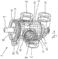
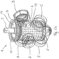
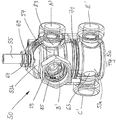
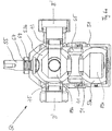
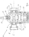
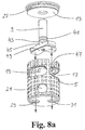
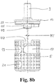
- FIGS. 1 to 3 and 8a , 8b a first preferred embodiment of the multi-way mixing valve 1 according to the invention is shown, wherein Fig. 1 shows a perspective overall view that Figures 2a to 2d show partially transparent perspective representations and in Fig. 3 a cross-sectional view is shown. In Figure 8a , 8b an exploded view of the interaction of certain parts is shown.
- the multi-way mixing valve 1 has an essentially hollow-cylindrical housing 3 on which five different connections A, B, C, D, E are arranged.
- a switching element 5 is provided, which is also designed as a hollow cylinder.
- a collar 7 is provided on the housing 3, on which a cover element 13 held by means of a snap ring 11 is arranged, a drive shaft 9 for actuating the switching element 5 being passed through the cover element 13.
- the housing 3 also has a cantilevered screw connection receptacle 15 on which the anti-rotation device (not shown) of an actuator (not shown) connected to the drive shaft 9 is arranged. This provides a rigid connection that prevents the actuator from turning around its own adjusting axis.
- the switching element 5 has different flow channels 17, 19, 21, 29, 31 which are arranged to correspond to the connections A, B, C, D, E.
- the three first connections A, B, D and the flow channels 17, 19 corresponding to them are formed in a first switching plane I.
- the connection A is arranged centrally and the connections D and B are arranged offset by 90 ° counterclockwise or clockwise.
- the associated flow channels 17, 19 are designed as elongated holes in the switching element 5 and each extend over an angular range of 90 ° or 45 °, so that either the connections A and B or the connections B and D can be connected to one another.
- the height or the outer radii of the elongated hole flow channels 17, 19 correspond to the respective inner diameters of the connections A, B, D, which are in contact with the switching element 5.
- the elongated hole flow channel 17 extends over a circumferential angle range of 90 ° and the elongated hole flow channel 19 extends over a circumferential angle range of 45 °.
- a web is provided between the two slot flow channels 17, 19, which is only made so wide that it structurally supports the switching element 5 and does not yet impair the flow.
- a single elongated hole flow channel could also be used can be provided, which then extends over a circumferential angle range of approximately 135 °.
- first of the second connections connection C
- connection C is arranged together with the flow channel 21 communicating therewith.
- This flow channel 21 is designed as a circular opening in the switching element 5, the diameter of which is dimensioned such that it corresponds to the inner diameter of the connection C on the switching element 5.
- the flow channel 21 is arranged below the flow channel 19 with respect to the longitudinal axis L of the multi-way mixing valve 1, the outer radius of the elongated flow channel 19 facing the elongated hole flow channel 17 being aligned with the circumference of the flow channel 21 with respect to the longitudinal axis L.
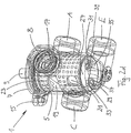
- two oppositely arranged flow channels 29, 31 are provided which, with corresponding connection openings 33, 35 of the connection E, form a third circuit level.
- the diameters of the flow channels 29, 31 in turn match the diameters of the associated connection openings 33, 35, the respective sum of the opening areas of the flow channels 29, 31 or the connection openings 33, 35 being identical to the opening area of the flow channel 21 or the connections A, B, C, D and the opening area inscribed in the elongated hole flow channels 17, 19.
- the diameters of the flow channels 29, 31 are kept in such a way that there are intermediate positions of the switching element 5 in which communication between the flow channels 29, 31 and the connection openings 33, 35 is prevented.
- the actuating element 5 is provided with an EPDM-coated surface and additionally has friction-reducing square depressions 23 arranged in a grid pattern.
- sealing rings (not shown) surrounding the connections A, B, C, D are provided and, with respect to the connection E, the flow channels 29, 31 are in the base 27 of the switching element 5 surrounded by sealing rings 37, 39.
- a sealing ring 25 is provided for sealing the housing 3 and the passage of the drive shaft 9 is sealed in a fluid-tight manner from the cover element 13 by means of sealing rings 41, 43.
- a position of the switching element 5 relative to the housing 3 is shown, with which a mixed state is realized in which the connections A and B of the first switching level I communicate with each other and the remaining connections C, D, E are blocked, i.e. in no fluid communication stand (this represents the mixed state a)).
- the further mixed states b) to f) can then be passed through successively, the mixed states a) to e) within one rotation 90 ° and mixed state f), i.e. the complete communication between ports D and E, in which port D is open at most with flow channel 19 and connection openings 33, 35 are open at most with corresponding flow channels 29, 31, after 135 ° is reached.
- a mechanical stop for example on the drive shaft 9 or a limit switch (not shown)
- Drive motor (not shown)
- a corresponding mechanical stop for example on the drive shaft 9 or a corresponding limit switch (not shown) of a drive motor (not shown) can also be provided to prevent further clockwise rotation beyond the mixed state f).
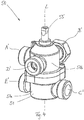
- FIG. 4 a second preferred embodiment of the multi-way mixing valve 50 according to the invention is shown in different views. It shows Fig. 4 a perspective overall view that Figures 5a to 5c show partially transparent perspective views and the Figures 6a to 6c show various sectional views of this multi-way mixing valve 50.
- this multi-way mixing valve 50 has a housing 51 which is constructed in two parts with a lower housing part 51a and an upper housing part 51b.
- an adjusting element 53 is arranged, which consists of two spherical half-shells 53a, 53b, which are connected with the aid of the connecting element 65 such that the interior spaces 89a, 89b of the spherical half-shells 53a, 53b are in fluid communication.
- a drive shaft 55 for driving the switching element 53 is passed through the housing 51.
- mechanical stops for example on the drive shaft 55 or a limit switch (not shown) of a drive motor (not shown), can be provided.
- two flow channels 57, 59 designed as elongated holes are formed, which in turn each extend over an angular range of 90 ° and 45 °.
- the elongated hole flow channel 59 is formed with a smaller height compared to the elongated hole flow channel 57. This dimensioning is advantageous if it is to be expected that the heating medium guided through the elongated hole flow channel 59 has a higher medium temperature, so that only relatively small amounts of hot medium and larger amounts of cold medium are then required to produce the warm mixture.
- two circular flow channels 61, 63 are provided, which are arranged offset from one another by an angle of 90 °.
- the one flow channel 63 is in turn aligned with the outer radius of the elongated flow channel 59 facing the elongated hole flow channel 57 in relation to the longitudinal axis L ′.
- each connection A ', B', C ', D', E ' has a cylinder insert 83 which is fastened with the aid of a snap ring 58 and is sealed with respect to the housing 51 by means of the sealing rings 73, 75, 77, 79, 81 is.
- This cylinder inserts 83 for example from PTFE are made, lie sealingly against the respective spherical half-shells 53a, 53b and prevent an undesired transfer of fluid from the respective connection A ', B', C ', D', E 'into another connection A', B ', C ', D', E '. Fluid is located in the space 91 formed between the housing 51 and the switching element 53.
- this multi-way mixing valve 50 has two switching levels I ', II', the connections A ', B', D 'and the corresponding elongated hole flow channels 57, 59 being in the first switching level, while the second switching level is II 'the connections C', E 'and the corresponding flow channels 61, 63 are located.
- the exact dimensioning of the multi-way mixing valves 1, 50 depends on the respective line classes and the desired media throughputs and can be adapted accordingly by a person skilled in the art.
- Fig. 7 the mixed states a) to f) of the multi-way mixing valve 1, 50 according to the invention are shown schematically. These mixed states a) to f) are passed through by successively turning the switching element 5, 53 clockwise from the starting position a) to the end position f). This adjustment by means of the drive shafts 9, 55 takes place either manually, or a corresponding drive motor (not shown) must be provided. As already shown above, there is no complete rotation of the switching element 5, 53 with respect to the housing 3, 51, but instead, starting from a stop position in mixed state a), a rotation over an angular range of 135 ° to the stop position in mixed state f).
- connections that are in direct fluid communication with one another are identified by the triangles filled in black.
- Fig. 7 only the connections A, B, C, D, E of the multi-way mixing valve 1 are given, but for the sake of clarity not those A ', B', C ', D', E 'of the multi-way mixing valve 50.
- ports A, B and C are connected to one another, so that heat medium flows from port A to port B and, in addition, port B is also supplied with heat medium from port C.
- the media flow from connection B is thus the sum of the media flows from connections A and C, so the underfloor heating 107 is successively supplied with heat medium from the unmixed heating circuit with the radiator heater 103, whereby an external media admixture takes place.
- This state b) is used when the return temperature of the unmixed heating circuit is higher than the return temperature of the mixed heating circuit.
- mixed state c) only ports B and C are in communication, which means that heat medium flows from port C to port B.
- heat medium from the return of the radiator heater 105 is mixed into connection B via the node 109.
- This state c) is used when the return temperature of the unmixed heating circuit matches the flow temperature of the mixed heating circuit.
- ports B, C and D are in fluid communication with one another.
- heat medium flows from port C to port B and also from port D to port B.
- port B there is a mixed amount of the media flows fed in from ports C and D.
- This state d) is used when the return temperature of the unmixed heating circuit is less than the flow temperature of the mixed heating circuit, so that heat medium from the heat source 101 is mixed into the mixed heating circuit.
- a commonly used interconnection is shown on the right-hand side with which the same mixed states can be implemented.
- the Alternative embodiment without five-way mixing valve 1 requires two three-way mixing valves 130, 130a and at least the additional two circulating pumps 131, 133 and corresponding controls are necessary, as a result of which this circuit is very complicated and costly.
- the circulating pump 113 is sufficient to supply the unmixed heating circuit 103, the mixed heating circuit 107 or the hot water storage heating circuit 103 with heat transfer medium as required.
- the additional provision of shut-off valves in this hot water storage heating circuit 103 is not necessary.
- the multi-way mixing valve 1, 50 according to the invention can also be used advantageously for numerous other applications, for example the interconnection of a mixed heating circuit with a heat source and a buffer store (not shown).
Description
Die vorliegende Erfindung betrifft ein Mehrwegemischventil nach dem Oberbegriff von Anspruch 1 und ein Verfahren zum zeitlichen Steuern nach dem Oberbegriff von Anspruch 10.The present invention relates to a multi-way mixing valve according to the preamble of
Mehrwegemischventile kommen in vielen hydraulischen Schaltungen zum Einsatz und werden vor allem in Warmwasserbereitungs- und/oder Heizungssystemen eingesetzt.Multi-way mixing valves are used in many hydraulic circuits and are mainly used in hot water and / or heating systems.
Bekannt ist beispielsweise aus der
Aus der
Eine mehrkreisige Heizungsanlage mit zwei Wärmesenken, die über einen Mischverteiler mit einer Wärmequelle verbunden sind, ist aus der
Die
Die
Die
Die Aufgabe der vorliegenden Erfindung besteht darin, ein Mehrwegemischventil zur Verfügung zu stellen, mit dem es möglich ist, mehr als zwei Wärmesenken mit einer Wärmequelle zu verbinden. Insbesondere soll es mit einem solchen Mehrwegemischventil möglich sein, einen Warmwasserspeicher ggf. auch in einen Mischkreislauf einzubinden und dabei zweckmäßigerweise eine Vorrangschaltung hinsichtlich des Warmwasserspeichers zu ermöglichen.The object of the present invention is to provide a multi-way mixing valve with which it is possible to connect more than two heat sinks to one heat source. In particular, with such a multi-way mixing valve it should be possible to integrate a hot water storage tank, if necessary, into a mixing circuit and thereby expediently enable a priority switching with regard to the hot water storage tank.
Diese Aufgabe wird gelöst mit dem erfindungsgemäßen Mehrwegemischventil nach Anspruch 1 und einem Verfahren zum zeitlichen Steuern nach Anspruch 10. Vorteilhafte Weiterbildungen sind in den abhängigen Unteransprüchen angegeben.This object is achieved with the multi-way mixing valve according to the invention according to
Die Erfinder haben erkannt, dass die gestellte Aufgabe dadurch konstruktiv besonders einfach gelöst werden kann, wenn zumindest fünf Anschlüsse für das Mehrwegemischventil bereitgestellt werden, die über ein im Ventilgehäuse gelagertes Schaltelement, das Strömungskanäle aufweist, miteinander verbindbar sind, wobei drei erste Anschlüsse einer ersten Schaltebene des Schaltelementes zugeordnet sind und zwei zweite Anschlüsse einer oder mehreren von der ersten Ebene abweichenden zweiten Schaltebene des Schaltelementes zugeordnet sind.The inventors have recognized that the task at hand can be achieved in a structurally particularly simple manner if at least five connections are provided for the multi-way mixing valve, which can be connected to one another via a switching element that is mounted in the valve housing and has flow channels, with three first connections of a first switching level of the switching element are assigned and two second connections are assigned to one or more second switching level of the switching element that deviates from the first level.
Vorteilhaft sind die ersten drei Anschlüsse um 90° versetzt zueinander in der ersten Schaltebene angeordnet, wodurch sich zwischen unterschiedlichen Mischzuständen kurze Schaltwege ergeben.The first three connections are advantageously arranged offset from one another by 90 ° in the first switching level, which results in short switching paths between different mixed states.
Wenn zumindest einer der zweiten Anschlüsse in Bezug auf die Projektion der ersten Schaltebene nicht mit einem der drei ersten Anschlüsse fluchtet, insbesondere um 90° versetzt zu den drei ersten Anschlüssen angeordnet ist, lässt sich eine Vorrangschaltung besonders einfach umsetzen.If at least one of the second connections is not aligned with one of the three first connections in relation to the projection of the first switching plane, in particular by 90 ° is arranged offset to the first three connections, a priority circuit can be implemented particularly easily.
Zweckmäßig sind die zweiten Anschlüsse in einer einheitlichen zweiten Schaltungsebene des Schaltelementes angeordnet. Dann lässt sich das Mehrwegemischventil besonders kompakt gestalten. Alternativ ist es natürlich auch möglich, die zweiten Anschlüsse in unterschiedlichen zweiten Schaltungsebenen des Schaltelementes anzuordnen, wodurch die entsprechenden Anschlüsse besser versetzt zueinander angeordnet werden können, um gegebenenfalls Vorteile bezüglich der Einbausituation zu erzielen.The second connections are expediently arranged in a uniform second circuit level of the switching element. Then the multi-way mixing valve can be designed to be particularly compact. Alternatively, it is of course also possible to arrange the second connections in different second circuit levels of the switching element, whereby the corresponding connections can be arranged better offset from one another in order to achieve advantages with regard to the installation situation if necessary.
Besonders bevorzugt ist es, wenn das Schaltelement bereichsweise Vertiefungen gegenüber dem Ventilgehäuse aufweist, die bevorzugt musterartig angeordnet und insbesondere in Form von Parallelogrammen ausgebildet sind.It is particularly preferred if the switching element has depressions in areas opposite the valve housing, which are preferably arranged in a pattern and in particular in the form of parallelograms.
Alternativ oder zusätzlich kann das Schaltelement auch eine Beschichtung zur Reibungsverminderung aufweisen, wobei die Beschichtung bevorzugt einen synthetischen Kautschuk aufweist und insbesondere als Ethylen-Propylen-Dien-Kautschuk (EPDM) ausgebildet ist. Dadurch wird zum einen verhindert, dass eine reibungsbedingte Abnutzung auftritt und zum anderen ist auch kein Ringspalt zur Drehung des Schaltelementes im Ventilgehäuse mehr nötig, was bei aus dem Stand der Technik bekannten Modellen zu einem Überlauf zwischen nicht miteinander verschalteten Anschlüssen führen konnte. Die für einen solchen Überlauf erforderlichen Druckerhöhungen sind insbesondere bei Heizkreisen möglich, da die Wärmequelle zur Betriebsaufrechterhaltung in regelmäßigen Abständen gestartet wird.As an alternative or in addition, the switching element can also have a coating to reduce friction, the coating preferably having a synthetic rubber and in particular being embodied as ethylene-propylene-diene rubber (EPDM). On the one hand, this prevents friction-related wear from occurring and, on the other hand, there is no longer any need for an annular gap to rotate the switching element in the valve housing, which in the case of models known from the prior art could lead to an overflow between non-interconnected connections. The pressure increases required for such an overflow are possible in particular in heating circuits, since the heat source is started at regular intervals to maintain operation.
Alternativ oder zusätzlich können auch Dichtelemente um die Anschlüsse und/oder um die Strömungskanäle angeordnet sein, die auch unter Druck einen Überlauf zwischen nicht verschalteten Anschlüssen verhindern. Hierfür kommen bevorzugt O-Ringe oder Zylindereinsätze aus PTFE (Polytetrafluorethylen) in Frage.As an alternative or in addition, sealing elements can also be arranged around the connections and / or around the flow channels, which prevent overflow between non-interconnected connections even under pressure. For this purpose, O-rings or cylinder inserts made of PTFE (polytetrafluoroethylene) are preferred.
In einer besonders bevorzugten Ausgestaltung sind mindestens zwei erste Strömungskanäle den drei ersten Anschlüssen zugeordnet, wobei die Strömungskanäle so ausgebildet sind, dass sie jeweils zwei der drei ersten Anschlüsse gleichzeitig überdecken können. Dadurch wird ein gradueller Übergang zwischen benachbarten Schaltzuständen ermöglicht. Alternativ kann auch ein einzelner Strömungskanal vorgesehen sein, der so ausgebildet ist, dass er gleichzeitig die drei ersten Anschlüsse gleichzeitig überdecken kann. Vorzugsweise sind die zwei Strömungskanäle bzw. der eine Strömungskanal als Langlöcher ausgebildet. In einer zweckmäßigen Ausgestaltung ist das Schaltelement als ggf. ein- oder beidseitig geschlossenes hohlzylindrisches Element ausgebildet oder alternativ als zwei miteinander verbundene kugelschalenartige Elemente.In a particularly preferred embodiment, at least two first flow channels are assigned to the three first connections, the flow channels being designed such that they can each cover two of the three first connections at the same time. This enables a gradual transition between neighboring switching states. Alternatively, a single flow channel can also be provided which is designed such that it can simultaneously cover the three first connections at the same time. The two flow channels or the one flow channel are preferably designed as elongated holes. In an expedient embodiment, the switching element is designed as a hollow cylindrical element which is closed on one or both sides, if necessary, or alternatively as two interconnected spherical shell-like elements.
Vorteilhaft sind zumindest einem Anschluss zwei zweite Strömungskanäle zugeordnet, wobei der Anschluss zumindest in einer Schalterstellung des Schaltelementes mit beiden Strömungskanälen gleichzeitig kommuniziert, wobei die beiden Strömungskanäle bevorzugt in einer Stirnfläche des Schaltelementes angeordnet sind. Durch diese Ausgestaltung kann eine präzise Sperrung dieses Anschlusses erreicht werden und gleichzeitig dennoch ein hoher Fluiddurchsatz in der zugeschalteten Stellung erreicht werden.Two second flow channels are advantageously assigned to at least one connection, the connection communicating with both flow channels simultaneously at least in one switch position of the switching element, the two flow channels preferably being arranged in an end face of the switching element. With this configuration, a precise blocking of this connection can be achieved and, at the same time, a high fluid throughput can be achieved in the connected position.
In diesem Zusammenhang ist es wünschenswert, dass die beiden Strömungskanäle in Summe zumindest dieselbe Querschnittsfläche aufweisen wie die Querschnittsfläche zumindest eines der ersten Anschlüsse, die bevorzugt jeweils dieselben Querschnittsflächen aufweisen. Dadurch werden unterschiedliche hydraulische Anschlusswiderstände des Mehrwegemischventils in Bezug auf die unterschiedlichen Schaltzustände des Ventils vermieden.In this context, it is desirable that the two flow channels in total have at least the same cross-sectional area as the cross-sectional area of at least one of the first connections, which preferably each have the same cross-sectional areas. This avoids different hydraulic connection resistances of the multi-way mixing valve in relation to the different switching states of the valve.
Erfindungsgemäß ist das Schaltelement im Zusammenhang mit den Anschlüssen so ausgebildet, dass durch Drehen des Schaltelementes um zumindest einen Winkelbereich einer Drehachse folgende Mischzustände angesteuert, bevorzugt sukzessive angesteuert werden können:
- a) Verbinden eines ersten der ersten Anschlüsse mit einem zweiten der ersten Anschlüsse,
- b) gleichzeitige Verbindung des ersten der ersten Anschlüsse mit dem zweiten der ersten Anschlüsse und eines ersten der zweiten Anschlüsse mit dem zweiten der ersten Anschlüsse,
- c) Verbinden des ersten der zweiten Anschlüsse mit dem zweiten der ersten Anschlüsse,
- d) gleichzeitiges Verbinden des ersten der zweiten Anschlüsse mit dem zweiten der ersten Anschlüsse und eines dritten der ersten Anschlüsse mit dem zweiten der ersten Anschlüsse,
- e) Verbinden des dritten der ersten Anschlüsse mit dem zweiten der ersten Anschlüsse und
- f) Verbinden des dritten der ersten Anschlüsse mit einem zweiten der zweiten Anschlüsse,
- a) connecting a first of the first connections to a second of the first connections,
- b) simultaneous connection of the first of the first connections to the second of the first connections and a first of the second connections to the second of the first connections,
- c) connecting the first of the second connections to the second of the first connections,
- d) simultaneous connection of the first of the second connections to the second of the first connections and a third of the first connections to the second of the first connections,
- e) connecting the third of the first connections to the second of the first connections and
- f) connecting the third of the first connections to a second of the second connections,
In einer vorteilhaften Weiterbildung dieser Ausgestaltung ist vorgesehen, dass der Drehwinkel des Schaltelementes zwischen den der Mischzuständen a) und f) insgesamt 135° beträgt, und bevorzugt ein Drehwinkel zwischen den der Mischzuständen a) und e) von 90° und ein Drehwinkel zwischen den der Mischzuständen e) und f) von 45° vorgesehen sind. Durch diese besondere Ausgestaltung wird erreicht, dass sehr schnell zwischen den verschiedenen Mischzuständen a) bis e) gewechselt werden kann und außerdem ein großer Einstellbereich für die Vorrangschaltung vorgesehen ist. Da bei einem Wechsel von Mischzustand e) hin zu der Mischzustand f) wie auch bei allen anderen der Mischzustandswechseln die Strömungskanäle die jeweiligen Anschlüsse jeweils nicht sofort vollständig überdecken, ist so eine sehr kontrollierte Dosierung des Fluidstromes in der Vorrangschaltung möglich.In an advantageous development of this embodiment, it is provided that the angle of rotation of the switching element between the mixed states a) and f) is a total of 135 °, and preferably an angle of rotation between those of the mixed states a) and e) of 90 ° and an angle of rotation between the Mixed states e) and f) of 45 ° are provided. This particular embodiment ensures that it is possible to switch very quickly between the various mixed states a) to e) and, in addition, a large setting range is provided for the priority switching. Since with a change from mixed state e) to mixed state f) as well as with all other mixed state changes, the flow channels do not immediately completely cover the respective connections, a very controlled dosage of the fluid flow in the priority circuit is possible.
Unabhängiger Schutz wird beansprucht für das erfindungsgemäße Verfahren zum zeitlichen Steuern der Verbindung von fünf Fluid führenden Anschlüssen untereinander, insbesondere den Anschlüssen des erfindungsgemäßen Mehrwegemischventils, das die folgenden möglichen Schritte beinhaltet:
- h) Verbinden eines ersten der ersten Anschlüsse mit einem zweiten der ersten Anschlüsse,
- i) gleichzeitige Verbindung des ersten der ersten Anschlüsse mit dem zweiten der ersten Anschlüsse und eines ersten der zweiten Anschlüsse mit dem zweiten der ersten Anschlüsse,
- k) Verbinden des ersten der zweiten Anschlüsse mit dem zweiten der ersten Anschlüsse,
- 1) gleichzeitiges Verbinden des ersten der zweiten Anschlüsse mit dem zweiten der ersten Anschlüsse und eines dritten der ersten Anschlüsse mit dem zweiten der ersten Anschlüsse,
- m) Verbinden des dritten der ersten Anschlüsse mit dem zweiten der ersten Anschlüsse und
- n) Verbinden des dritten der ersten Anschlüsse mit einem zweiten der zweiten Anschlüsse.
- h) connecting a first of the first connections to a second of the first connections,
- i) simultaneous connection of the first of the first connections to the second of the first connections and a first of the second connections to the second of the first connections,
- k) connecting the first of the second connections to the second of the first connections,
- 1) simultaneous connection of the first of the second connections to the second of the first connections and a third of the first connections to the second of the first connections,
- m) connecting the third of the first connections to the second of the first connections and
- n) connecting the third of the first connections to a second of the second connections.
Wenn der zweite Anschluss der ersten Anschlüsse dann beispielsweise mit dem Vorlauf eines gemischten Heizkreises verbunden ist, wird dieser Heizkreis stets betrieben und je nach Anforderung kann bedarfsweise Wärme zugemischt werden von einer Heizquelle, einem ungemischten Heizkreis oder ggf. von einem Pufferspeicher. Mit Schritt n) kann so eine Vorrangschaltung beispielsweise für die Warmwasseraufbereitung bzw. die Pufferspeicherbeladung verwirklicht werden, bei der kein Betrieb des gemischten Heizkreises erfolgt.If the second connection of the first connection is then connected, for example, to the flow of a mixed heating circuit, this heating circuit is always operated and, depending on the requirements, heat can be added from a heating source, an unmixed heating circuit or, if necessary, from a buffer storage tank. With step n), a priority circuit can be implemented, for example for hot water preparation or buffer storage, in which there is no operation of the mixed heating circuit.
Die Merkmale der erfindungsgemäßen Gegenstände und weitere Vorteile werden im Folgenden anhand der Beschreibung bevorzugter Ausführungsbeispiele im Zusammenhang mit den Figuren deutlich werden. Dabei zeigen:
- Fig. 1
- das erfindungsgemäße Mehrwegemischventil in einer ersten bevorzugten Ausgestaltung in einer perspektivischen Ansicht,
- Fig. 2a bis 2d
- das erfindungsgemäße Mehrwegemischventil nach
Fig. 1 in teilweise transparenten perspektivischen Darstellungen, - Fig. 3
- einen Schnitt durch das erfindungsgemäße Mehrwegemischventil nach
Fig. 1 , - Fig. 4
- das erfindungsgemäße Mehrwegemischventil in einer zweiten bevorzugten Ausgestaltung in einer perspektivischen Ansicht,
- Fig.
5a bis 5c - das erfindungsgemäße Mehrwegemischventil nach
Fig. 4 in teilweise transparenten perspektivischen Ansichten, - Fig. 6a bis 6c
- das erfindungsgemäße Mehrwegemischventil nach
Fig. 4 in Schnittansichten, - Fig. 7
- eine Übersicht über die mit dem erfindungsgemäßen Mehrwegemischventil ermöglichten Mischzustände
- Fig. 8a, 8b
- das erfindungsgemäße Mehrwegemischventil nach
Fig. 1 in einer teilweisen Explosionsdarstellung, und zwar in einer perspektivischen Ansicht und einer Draufsicht, und - Fig. 9
- eine Gegenüberstellung zweier mehrkreisiger Heizanlagen, die mit dem erfindungsgemäßen Mehrwegemischventil verschaltet sind oder nach derzeit bekannter Verschaltung.
- Fig. 1
- the multi-way mixing valve according to the invention in a first preferred embodiment in a perspective view,
- Figures 2a to 2d
- the multi-way mixing valve according to the invention
Fig. 1 in partially transparent perspective representations, - Fig. 3
- a section through the multi-way mixing valve according to the invention
Fig. 1 , - Fig. 4
- the multi-way mixing valve according to the invention in a second preferred embodiment in a perspective view,
- Figures 5a to 5c
- the multi-way mixing valve according to the invention
Fig. 4 in partially transparent perspective views, - Figures 6a to 6c
- the multi-way mixing valve according to the invention
Fig. 4 in sectional views, - Fig. 7
- an overview of the mixing states made possible with the multi-way mixing valve according to the invention
- Figures 8a, 8b
- the multi-way mixing valve according to the invention
Fig. 1 in a partially exploded view, namely in a perspective view and a plan view, and - Fig. 9
- a comparison of two multi-circuit heating systems that are connected to the multi-way mixing valve according to the invention or according to currently known interconnection.
In den
Es ist zu erkennen, dass das Mehrwegemischventil 1 ein im Wesentlichen hohlzylindrisch ausgebildetes Gehäuse 3 aufweist, an dem fünf verschiedene Anschlüsse A, B, C, D, E angeordnet sind. Im Inneren des Gehäuses 3 ist ein Schaltelement 5 vorgesehen, das ebenfalls hohlzylindrisch ausgebildet ist. An dem Gehäuse 3 ist ein Kragen 7 vorgesehen, an dem ein mittels eines Sprengringes 11 gehaltenes Abdeckelement 13 angeordnet ist, wobei durch das Abdeckelement 13 eine Antriebswelle 9 zur Betätigung des Schaltelementes 5 durchgeführt ist. Das Gehäuse 3 weist außerdem eine auskragend angeordnete Schraubverbindungsaufnahme 15 auf, an der die Verdrehsicherung (nicht gezeigt) eines mit der Antriebswelle 9 verbundenen Stellantriebs (nicht gezeigt) angeordnet wird. Dadurch wird eine starre Verbindung bereit gestellt, die verhindert, dass sich der Stellantrieb um die eigene Stellachse drehen kann.It can be seen that the
Das Schaltelement 5 weist verschiedene Strömungskanäle 17, 19, 21, 29, 31 auf, die korrespondierend zu den Anschlüssen A, B, C, D, E angeordnet sind. Die drei ersten Anschlüsse A, B, D und die dazu korrespondierenden Strömungskanäle 17, 19 sind dabei in einer ersten Schaltebene I ausgebildet. Dabei ist der Anschluss A zentral angeordnet und jeweils um 90° gegen den Uhrzeigersinn bzw. im Uhrzeigersinn versetzt sind die Anschlüsse D bzw. B angeordnet. Die zugehörigen Strömungskanäle 17, 19 sind als Langlochdurchbrechungen im Schaltelement 5 ausgebildet und erstrecken sich jeweils über einen Winkelbereich von 90° bzw. 45°, so dass wahlweise die Anschlüsse A und B oder die Anschlüsse B und D miteinanderverbindbar sind. Die Höhe bzw. die Außenradien der Langlochströmungskanäle 17, 19 stimmen mit den jeweiligen Innendurchmessern der Anschlüsse A, B, D, die am Schaltelement 5 anliegen, überein. Der Langlochströmungskanal 17 erstreckt sich dabei über einen Umfangswinkelbereich von 90° und der Langlochströmungskanal 19 erstreckt sich dabei über einen Umfangswinkelbereich von 45°. Zwischen den beiden Langlochströmungskanälen 17, 19 ist ein Steg vorgesehen, der nur so breit ausgeführt ist, dass er das Schaltelement 5 konstruktiv abstützt und dabei noch nicht strömungstechnisch beeinträchtigt. Anstelle der beiden getrennt ausgebildeten Langlochströmungskanäle 17, 19 könnte auch ein einzelner Langlochströmungskanal vorgesehen werden, der sich dann über einen Umfangswinkelbereich von ca. 135° erstreckt.The switching
In einer ersten Schaltungsebene II der zweiten Schaltungsebenen ist der erste der zweiten Anschlüsse, Anschluss C, zusammen mit dem damit kommunizierenden Strömungskanal 21 angeordnet. Dieser Strömungskanal 21 ist als kreisförmige Durchbrechung im Schaltelement 5 ausgebildet, wobei dessen Durchmesser so bemessen ist, dass er mit dem Innendurchmesser des Anschlusses C am Schaltelement 5 übereinstimmt. Der Strömungskanal 21 ist in Bezug auf die Längsachse L des Mehrwegemischventils 1 unterhalb des Strömungskanals 19 angeordnet, wobei der zum Langlochströmungskanal 17 weisende Außenradius des Langlochströmungskanals 19 mit dem Umfang des Strömungskanals 21 in Bezug auf die Längsachse L fluchtet.In a first circuit level II of the second circuit level, the first of the second connections, connection C, is arranged together with the
Im Boden 27 des Schaltelements 5, der zum Anschluss E weist, sind zwei gegenüberliegend angeordnete Strömungskanäle 29, 31 vorgesehen, die mit korrespondierenden Anschlussöffnungen 33, 35 des Anschlusses E eine dritte Schaltungsebene ausbilden. Die Durchmesser der Strömungskanäle 29, 31 stimmen dabei wiederum mit den Durchmessern der zugehörigen Anschlussöffnungen 33, 35 überein, wobei die jeweilige Summe der Öffnungsflächen der Strömungskanäle 29, 31 bzw. der Anschlussöffnungen 33, 35 identisch ist zur Öffnungsfläche des Strömungskanals 21 bzw. der Anschlüsse A, B, C, D und die in die Langlochströmungskanäle 17, 19 einbeschriebene Öffnungsfläche. Die Durchmesser der Strömungskanäle 29, 31 sind dabei so gehalten, dass Zwischenstellungen des Schaltelements 5 vorhanden sind, in denen die Kommunikation zwischen den Strömungskanälen 29, 31 und den Anschlussöffnungen 33, 35 unterbunden ist.In the bottom 27 of the
Um einen verschleißfreien und dabei abgedichteten Lauf des Stellelements 5 im Gehäuse 3 zu ermöglichen, ist das Stellelement 5 mit einer EPDM beschichteten Oberfläche versehen und weist zusätzlich rasterartig angeordnete, Reibung vermindernde quadratische Vertiefungen 23 auf. Zur weiteren Abdichtung der Anschlüsse A, B, C, D gegenüber dem Schaltelement 5 sind die Anschlüsse A, B, C, D umgebende Dichtringe (nicht gezeigt) vorgesehen und bezüglich des Anschlusses E sind die Strömungskanäle 29, 31 im Boden 27 des Schaltelements 5 von Dichtringen 37, 39 umgeben. Weiterhin ist ein Dichtring 25 zur Abdichtung des Gehäuses 3 vorgesehen und die Durchführung der Antriebswelle 9 ist gegenüber dem Abdeckelement 13 mittels Dichtringen 41, 43 fluiddicht abgedichtet.In order to enable the
In den
Dadurch, dass das Schaltelement durch Drehung der Antriebswelle 9 im Uhrzeigersinn (von oben auf den Deckel 7 schauend) bewegt wird, können dann die weiteren Mischzustände b) bis f) sukzessive durchlaufen werden, wobei die Mischzustände a) bis e) innerhalb einer Drehung um 90° durchlaufen werden und Mischzustand f), also die vollständige Kommunikation zwischen den Anschlüssen D und E, bei der Anschluss D maximal mit Strömungskanal 19 geöffnet ist und die Anschlussöffnungen 33, 35 maximal mit den korrespondierenden Strömungskanälen 29, 31 geöffnet sind, nach 135° erreicht ist.Because the switching element is moved clockwise by rotating the drive shaft 9 (looking at the
Zur Verhinderung einer Drehung gegen den Uhrzeigersinn von Mischzustand a) aus, wodurch eine Verbindung der Anschlüsse A, B, C, E ermöglicht würde, können ein mechanischer Anschlag (nicht gezeigt) bspw. auf der Antriebswelle 9 oder ein Endlagenschalter (nicht gezeigt) eines Antriebsmotors (nicht gezeigt) vorgesehen sein. Gleichfalls können zur Verhinderung eines Weiterdrehens im Uhrzeigersinn über den Mischzustand f) hinaus ebenfalls ein entsprechender mechanischer Anschlag (nicht gezeigt) bspw. auf der Antriebswelle 9 oder ein entsprechender Endlagenschalter (nicht gezeigt) eines Antriebsmotors (nicht gezeigt) vorgesehen sein.To prevent counter-clockwise rotation from mixed state a), which would enable the connections A, B, C, E to be connected, a mechanical stop (not shown), for example on the
Aus der in
In den
Es ist zu erkennen, dass dieses Mehrwegemischventil 50 ein Gehäuse 51 aufweist, das zweiteilig mit einem unteren Gehäuseteil 51a und einem oberen Gehäuseteil 51b aufgebaut ist. Im Inneren des Gehäuses 51 ist ein Stellelement 53 angeordnet, das aus zwei Kugelhalbschalen 53a, 53b besteht, die mit Hilfe des Verbindungselementes 65 so verbunden sind, dass die Innenräume 89a, 89b der Kugelhalbschalen 53a, 53b in fluider Kommunikation stehen. Durch das Gehäuse 51 ist eine Antriebswelle 55 zum Antrieb des Schaltelementes 53 durchgeführt. Auch hier können mechanische Anschläge (nicht gezeigt) bspw. auf der Antriebswelle 55 oder ein Endlagenschalter (nicht gezeigt) eines Antriebsmotors (nicht gezeigt) vorgesehen sein.It can be seen that this
In der oberen Halbkugelschale 53b sind zwei als Langlöcher ausgebildete Strömungskanäle 57, 59 ausgebildet, die sich wiederum jeweils über einen Winkelbereich von 90° bzw. 45° erstrecken. Der Langlochströmungskanal 59 ist im Vergleich zum Langlochströmungskanal 57 mit geringerer Höhe ausgebildet. Diese Dimensionierung ist vorteilhaft, wenn zu erwarten ist, dass das durch den Langlochströmungskanal 59 geführte Wärmemedium eine höhere Medientemperatur aufweist, so dass dann zur Herstellung der warmen Mischung nur relativ geringe Mengen heißen Mediums und größere Mengen kalten Mediums benötigt werden.In the upper hemispherical shell 53b, two
In der unteren Halbkugelschale 53a sind zwei kreisförmige Strömungskanäle 61, 63 vorgesehen, die um einen Winkel von 90° versetzt zueinander angeordnet sind. Der eine Strömungskanal 63 ist dabei wiederum in Bezug auf die Längsachse L' fluchtend mit dem zum Langlochströmungskanal 57 weisenden Außenradius des Langlochströmungskanals 59 ausgerichtet.In the lower
Das Gehäuse 51 ist nach außen hin durch die Ringdichtungen 67, 69 und 71 abgedichtet. Zusätzlich weist jeder Anschluss A', B', C', D', E' einen Zylindereinsatz 83 auf, der mit Hilfe eines Sprengringes 58 befestigt ist und jeweils mittels der Dichtungsringe 73, 75, 77, 79, 81 gegenüber dem Gehäuse 51 abgedichtet ist. Diese Zylindereinsätze 83, die beispielsweise aus PTFE gefertigt sind, liegen abdichtend an den jeweiligen Kugelhalbschalen 53a, 53b an und verhindern einen ungewünschten Übertritt von Fluid aus dem jeweiligen Anschluss A', B', C', D', E' in einen anderen Anschluss A', B', C', D', E'. In dem zwischen Gehäuse 51 und Schaltelement 53 ausgebildeten Zwischenraum 91 befindet sich Fluid.The
Es ist zu erkennen, dass dieses erfindungsgemäße Mehrwegemischventil 50 zwei Schaltebenen I', II' aufweist, wobei sich in der ersten Schaltebene die Anschlüsse A', B', D' und die korrespondierenden Langlochströmungskanäle 57, 59 befinden, während sich in der zweiten Schaltebene II' die Anschlüsse C', E' und die korrespondierenden Strömungskanäle 61, 63 befinden.It can be seen that this
Es ist zu erkennen, dass bei beiden Mehrwegemischventilen 1, 50 eine sehr reibungsarme Lagerung der Schaltelemente 5, 53 in den Gehäusen 3, 51 besteht und dabei durch die verwendeten Abdichtungen dennoch sehr wirksam ein Fluidübertritt zwischen nicht verschalteten Anschlüssen besteht, so dass auch bei kurzzeitig auftretenden hohen Drücken kein Fluid übertritt.It can be seen that in both
Die genaue Bemaßung der Mehrwegemischventile 1, 50 richtet sich nach den jeweiligen Leitungsklassen und den gewünschten Mediendurchsätzen und kann vom Fachmann entsprechend angepasst werden.The exact dimensioning of the
In
Mit Hilfe der schwarz ausgefüllten Dreiecke sind diejenigen Anschlüsse bezeichnet, die in direkter fluider Kommunikation miteinander stehen. Dabei sind in
Es ist zu erkennen, dass in Mischzustand a) die Anschlüsse A und B direkt miteinander kommunizieren, während keine Kommunikation mit den Anschlüssen C, D und E stattfindet.It can be seen that in mixed state a) the connections A and B communicate directly with one another, while there is no communication with the connections C, D and E.
Wenn also beispielsweise im Rahmen einer Verschaltung 100, wie sie in
- Anschluss A mit dem
Rücklauf der Fußbodenheizung 107, - Anschluss B mit dem
Vorlauf der Fußbodenheizung 107, - Anschluss C mit dem
Rücklauf der Heizkörperheizung 105, dem Rücklauf desWarmwasserspeichers 103 und demRücklauf der Fußbodenheizung 107 mit Hilfe der Knotenpunkte 109, 111 verbunden ist, - Anschluss D mit dem Vorlauf aus der
Wärmequelle 101 und - Anschluss E mit dem Vorlauf des
Wärmespeichers 103 verbunden sind und - der Wärmequellevorlauf parallel mit dem
Vorlauf der Fußbodenheizung 107 und der Wärmequellenrücklauf parallel mit demRücklauf der Fußbodenheizung 107 verbunden sind, dann würde im Fall des Mischzustandes a) das Wärmemedium nur von Anschluss A nach Anschluss B strömen, das heißt es würde ein geschlossener hydraulischer Kreis für dieFußbodenheizung 107 bestehen, dem kein Medium zugeführt wird und der gegebenenfalls mittels der Pumpe 113 sukzessive ausgekühlt wird. Hier gibt es keine Wärmeanforderung in dem gemischten Heizkreis, aber eine Wärmeanforderung in dem ungemischten Heizkreis.
- Connection A with the return of the
underfloor heating 107, - Connection B with the flow of the
underfloor heating 107, - Connection C is connected to the return of the
radiator heating 105, the return of the hotwater storage tank 103 and the return of theunderfloor heating 107 with the help of the nodes 109, 111, - Connection D with the flow from the
heat source 101 and - Connection E are connected to the flow of the
heat accumulator 103 and - If the heat source flow is connected in parallel with the flow of the
underfloor heating 107 and the heat source return is connected in parallel with the return of theunderfloor heating 107, then in the case of the mixed state a) the heat medium would only flow from port A to port B, i.e. a closed hydraulic circuit for theunderfloor heating 107 exist, to which no medium is fed and which is optionally successively cooled by means of thepump 113. There is no heat demand in the mixed heating circuit, but there is a heat demand in the unmixed heating circuit.
Bei Mischzustand b) sind die Anschlüsse A, B und C miteinander verbunden, so dass Wärmemedium von Anschluss A nach Anschluss B strömen und zusätzlich Anschluss B auch von Anschluss C Wärmemedium zugeführt wird. Der Medienstrom aus Anschluss B ist somit die Summe der Medienströme aus den Anschlüssen A und C, es wird also der Fußbodenheizung 107 sukzessive Wärmemedium aus dem ungemischten Heizkreis mit der Heizkörperheizung 103 zugeführt, wodurch eine externe Medienzumischung erfolgt. Hier gibt es sowohl Wärmeanforderung in dem gemischten als auch in dem ungemischten Heizkreis. Dieser Zustand b) wird eingesetzt, wenn die Rücklauftemperatur des ungemischten Heizkreises größer ist als die Rücklauftemperatur des gemischten Heizkreises.In mixed state b), ports A, B and C are connected to one another, so that heat medium flows from port A to port B and, in addition, port B is also supplied with heat medium from port C. The media flow from connection B is thus the sum of the media flows from connections A and C, so the
Bei Mischzustand c) stehen nur die Anschlüsse B und C in Kommunikation, wodurch Wärmemedium von Anschluss C nach Anschluss B strömt. Hier wird also dem Anschluss B Wärmemedium aus dem Rücklauf der Heizkörperheizung 105 über den Knotenpunkt 109 zugemischt. Hier gibt es sowohl Wärmeanforderung in dem gemischten als auch in dem ungemischten Heizkreis. Dieser Zustand c) wird eingesetzt, wenn die Rücklauftemperatur des ungemischten Heizkreises mit der Vorlauftemperatur des gemischten Heizkreises übereinstimmt.In mixed state c) only ports B and C are in communication, which means that heat medium flows from port C to port B. Here, heat medium from the return of the
Bei Mischzustand d) befinden sich die Anschlüsse B, C und D in fluider Kommunikation untereinander. In diesem Fall strömt Wärmemedium von Anschluss C nach Anschluss B und auch von Anschluss D nach Anschluss B. Bei Anschluss B ergibt sich also eine Mischmenge aus den zugespeisten Medienströmen der Anschlüsse C und D. Hier gibt es sowohl Wärmeanforderung in dem gemischten als auch in dem ungemischten Heizkreis. Dieser Zustand d) wird eingesetzt, wenn die Rücklauftemperatur des ungemischten Heizkreises kleiner ist kleiner als die Vorlauftemperatur des gemischten Heizkreises, so dass Wärmemedium aus der Wärmequelle 101 dem gemischten Heizkreis zugemischt wird.In the mixed state d), ports B, C and D are in fluid communication with one another. In this case, heat medium flows from port C to port B and also from port D to port B. At port B, there is a mixed amount of the media flows fed in from ports C and D. Here there is both a heat demand in the mixed and in the unmixed heating circuit. This state d) is used when the return temperature of the unmixed heating circuit is less than the flow temperature of the mixed heating circuit, so that heat medium from the
Bei Mischzustand e) sind nur die Anschlüsse B und D miteinander verschaltet, während die Anschlüsse A, C und E geschlossen sind. In diesem Fall strömt das Medium von Anschluss D zu B, das heißt der gemischte Heizkreis wird ausschließlich über die Wärmequelle 101 versorgt, während im ungemischten Heizkreis keine Medienanforderung besteht. Hier ist die Vorlauftemperatur des gemischten Heizkreises gleich der Temperatur des Verlaufs der Wärmequelle 101.In mixed state e), only connections B and D are interconnected, while connections A, C and E are closed. In this case, the medium flows from port D to B, that is, the mixed heating circuit is supplied exclusively via the
Schließlich ist bei Mischzustand f) eine direkte Kommunikation der Anschlüsse D und E geschaltet, so dass Medium von Anschluss D nach Anschluss E strömt. Hierdurch kann eine Vorrangschaltung der Beladung des Warmwasserspeichers 103 aus der Wärmequelle 101 verwirklicht werden, nämlich dann, wenn entweder sowohl für den gemischten Kreis 107 als auch für den ungemischten Kreis 105 keine Medienanforderung besteht oder aktuell eine Warmwasseranforderung besteht. Das im Warmwasserspeicher 103 gespeicherte warme Wasser kann dann im Bedarfsfall dem Warmwasserspeicher 103 entnommen werden.Finally, in mixed state f), direct communication between ports D and E is switched so that medium flows from port D to port E. This allows priority switching of the loading of the hot
In
Insgesamt ist also festzustellen, dass mit dem erfindungsgemäßen Mehrwegemischventil 1, 50 sich eine wesentlich einfachere, kompaktere und damit auch kostengünstigere hydraulische Verschaltung einer Wärmequelle 101 mit drei Wärmesenken 103, 105, 107 erreichen lässt.Overall, it can be stated that with the
Aber auch für zahlreiche weitere Anwendungsfälle, bspw. der Verschaltung eines gemischten Heizkreises mit einer Wärmequelle und einem Pufferspeicher (nicht gezeigt), lässt sich das erfindungsgemäße Mehrwegemischventil 1, 50 vorteilhaft einsetzen.However, the
Claims (11)
- Multiway mixing valve (1; 50) for hot water preparation systems and/or heating systems comprising a valve housing (3; 51) and at least five connections (A, B, C, D, E), which are connectable to one another via a switching element (5; 53), which is supported in the valve housing (3; 51) and comprises flow channels (17, 19, 21, 29, 31; 57, 59, 61, 63), wherein three first connections (A, B, D) are associated with a first switching level (I; I') of the switching element (5; 53) and two second connections (C, E) are associated with one or more second switching levels (II; II') of the switching element (5; 53) that differ from the first switching level (I; I'), characterised in that
the switching element (5; 53) is formed in conjunction with the connections (A, B, C, D, E) such that by rotating the switching element (5; 53) about at least one angular range of an axis of rotation (L; L'), the following mixed states can be triggered, preferably successively triggered:a) connection of a first (A) of the first connections to a second (B) of the first connections,b) simultaneous connection of the first (A) of the first connections to the second (B) of the first connections and of a first (C) of the second connections to the second (B) of the first connections,c) connection of the first (C) of the second connections to the second (B) of the first connections,d) simultaneous connection of the first (C) of the second connections to the second (B) of the first connections and of a third (D) of the first connections to the second (B) of the first connections,e) connection of the third (D) of the first connections to the second (B) of the first connections andf) connection of the third (D) of the first connections to a second (E) of the second connections, wherein a first stop position is formed for the switching element (5; 53), in which position the mixed state a) is present, and/or a second stop position is formed in which the mixed state f) is present, whereby interconnection of three heat sinks with a heat source can be achieved, wherein with the mixed state f) priority switching can be realised for the exclusive charging of a heat store, wherein in this case no admixture to the other heat sinks is undertaken. - Multiway mixing valve (1; 50) according to claim 1, characterised in that the first three connections (A, B, D) are arranged offset by 90° to one another in the first switching level (I; I').
- Multiway mixing valve (1; 50) according to claim 1 or 2, characterised in that with regard to the projection of the first switching level (I; I'), at least one of the second connections (C) is not in line with one of the first three connections (A, B, D), is arranged in particular offset by 90° to the three first connections (A, B, D), and/or that the second connections (61, 63) are arranged in a uniform second switching level (II') of the switching element (53).
- Multiway mixing valve (1) according to any one of the preceding claims, characterised in that the switching element (5) comprises depressions (23) in areas relative to the valve housing (3), which are preferably arranged pattern-like and are formed in particular in the shape of parallelograms and/or that the switching element (5) comprises a coating to reduce friction, wherein the coating preferably comprises a synthetic rubber, and is formed in particular as an EPDM coating.
- Multiway mixing valve (1; 50) according to any one of the preceding claims, characterised in that at least two first flow channels (17, 19; 57, 59) are associated with the three first connections (A, B, D), wherein the two flow channels (17, 19; 57, 59) are formed such that they can each cover two of the three first connections (A, B, D) simultaneously, and/or that the switching element (5; 53) is formed if applicable as a hollow cylindrical element that is closed on one or both sides or as two spherical-shell-like elements (53a, 53b) connected to one another.
- Multiway mixing valve (5) according to any one of the preceding claims, characterised in that two second flow channels (29, 31) are associated with at least one connection (E), wherein the connection (E) communicates simultaneously with both flow channels (29, 31) at least in one switching position of the switching element (5), wherein the two flow channels (29, 31) are preferably arranged in an end face of the switching element (5).
- Multiway mixing valve (5) according to claim 6, characterised in that the two flow channels (29, 31) have at least the same cross-sectional area in total as the cross-sectional area at least of one of the first connections (A, B, D), which preferably each have the same cross-sectional areas.
- Multiway mixing valve (1; 50) according to any one of the preceding claims, characterised in that formed for the switching element (5; 53) is a first stop position, in which the position a) is present, and/or a second stop position is formed in which the position f) is present, wherein the first and second stop position are realised in particular via end position switches of a motor driving the switching element (5; 53).
- Multiway mixing valve (1; 50) according to claim 8, characterised in that the angle of rotation of the switching element (5; 53) between the mixed states a) and f) is 135°, and preferably an angle of rotation between the mixed states a) and e) of 90° and an angle of rotation between the mixed states e) and f) of 45° are provided.
- Method for time control of the connection of five fluid-carrying (A, B, C, D, E) connections to one another in a multiway mixing valve (1; 50) for hot water preparation systems and/or heating systems, wherein the multiway mixing valve (1; 50) comprises a valve housing (3; 51) and at least five connections (A, B, C, D, E), which are connectable to one another via a switching element (5; 53), which is supported in the valve housing (3; 51) and comprises flow channels (17, 19, 21, 29, 31; 57, 59, 61, 63), wherein three first connections (A, B, D) are associated with a first switching level (I; I') of the switching element (5; 53) and two second connections (C, E) are associated with one or more second switching levels (II; II') of the switching element (5; 53) that differ from the first switching level (I; I'), characterised by the following possible steps:h) connection of a first (A) of the first connections to a second (B) of the first connections,i) simultaneous connection of the first (A) of the first connections to the second (B) of the first connections and of a first (C) of the second connections to the second (B) of the first connections,k) connection of the first (C) of the second connections to the second (B) of the first connections,I) simultaneous connection of the first (C) of the second connections to the second (B) of the first connections and of a third (D) of the first connections to the second (B) of the first connections,m) connection of the third (D) of the first connections to the second (B) of the first connections andn) connection of the third (D) of the first connections to a second (E) of the second connections, wherein a first stop position is formed for the switching element (5; 53), in which position the step h) is present, and/or a second stop position is formed in which the step n) is present, whereby interconnection of three heat sinks with a heat source can be achieved, wherein with the step n) priority switching can be realised for the exclusive charging of a heat store, wherein in this case no admixture to the other heat sinks is undertaken.
- Method according to claim 10, characterised in that the multiway mixing valve (1; 50) according to any one of claims 1 to 9 is formed.
Applications Claiming Priority (2)
| Application Number | Priority Date | Filing Date | Title |
|---|---|---|---|
| DE102012024585.8A DE102012024585A1 (en) | 2012-12-17 | 2012-12-17 | Multiway mixing valve and method for timing a multiway mixing valve |
| PCT/EP2013/003787 WO2014095021A1 (en) | 2012-12-17 | 2013-12-16 | Multiple-way mixing valve and method for controlling a multiple-way mixing valve over time |
Publications (2)
| Publication Number | Publication Date |
|---|---|
| EP2932142A1 EP2932142A1 (en) | 2015-10-21 |
| EP2932142B1 true EP2932142B1 (en) | 2021-06-09 |
Family
ID=49911452
Family Applications (1)
| Application Number | Title | Priority Date | Filing Date |
|---|---|---|---|
| EP13815380.4A Active EP2932142B1 (en) | 2012-12-17 | 2013-12-16 | Multiple-way mixing valve and method for controlling a multiple-way mixing valve over time |
Country Status (5)
| Country | Link |
|---|---|
| EP (1) | EP2932142B1 (en) |
| CN (1) | CN105190137A (en) |
| DE (1) | DE102012024585A1 (en) |
| EA (1) | EA201591146A1 (en) |
| WO (1) | WO2014095021A1 (en) |
Cited By (1)
| Publication number | Priority date | Publication date | Assignee | Title |
|---|---|---|---|---|
| DE102022114176A1 (en) | 2022-06-03 | 2023-12-14 | Schaeffler Technologies AG & Co. KG | Thermal management module and rotary slide valve with rotary slide valve with channels crossed over without cutting in an axial plane as well as an axially offset additional channel |
Families Citing this family (3)
| Publication number | Priority date | Publication date | Assignee | Title |
|---|---|---|---|---|
| DE102009035349B4 (en) | 2009-07-30 | 2018-06-28 | BorgWarner Esslingen GmbH | Control device for the coolant flow in the cooling circuit of an internal combustion engine |
| EP3204701A1 (en) * | 2014-10-10 | 2017-08-16 | Solabcool B.v. | Cooling system, reactor vessel and rotary valve |
| CN107559459B (en) * | 2017-09-11 | 2024-04-12 | 南宁宇立仪器有限公司 | Electric servo valve |
Family Cites Families (8)
| Publication number | Priority date | Publication date | Assignee | Title |
|---|---|---|---|---|
| US5927330A (en) * | 1996-02-06 | 1999-07-27 | Oil States Industries | Modular, high-volume, rotary selector valve |
| DE19614868A1 (en) * | 1996-04-16 | 1997-10-23 | Zahnradfabrik Friedrichshafen | Automatic transmission gear change slide |
| DE10214242B4 (en) | 2001-03-26 | 2014-10-23 | Hg Baunach Gmbh & Co Kg | Multi-way mixing valve and method for its timing |
| DE10242727B4 (en) | 2002-09-13 | 2008-01-10 | First, Franc | Valve |
| WO2006109639A1 (en) * | 2005-04-08 | 2006-10-19 | Ihara Science Corporation | Manifold valve and psa device having the same |
| DE102007009194B3 (en) * | 2007-02-26 | 2008-09-25 | Kioto Clear Energy Ag | Multi-way valve |
| DE102008013124A1 (en) | 2008-03-07 | 2009-09-10 | Meibes System-Technik Gmbh | Multi circuit heating system for use as e.g. low temperature circuit in floor heating, has mixer valve provided for adjusting different operating conditions such as volumetric flow of unblended circuit equal to zero, of heating circuit |
| EP2397777B1 (en) * | 2010-06-19 | 2016-08-03 | Grundfos Management A/S | Housing unit for a heating system |
-
2012
- 2012-12-17 DE DE102012024585.8A patent/DE102012024585A1/en not_active Withdrawn
-
2013
- 2013-12-16 CN CN201380071797.8A patent/CN105190137A/en active Pending
- 2013-12-16 EP EP13815380.4A patent/EP2932142B1/en active Active
- 2013-12-16 WO PCT/EP2013/003787 patent/WO2014095021A1/en active Application Filing
- 2013-12-16 EA EA201591146A patent/EA201591146A1/en unknown
Non-Patent Citations (1)
| Title |
|---|
| None * |
Cited By (1)
| Publication number | Priority date | Publication date | Assignee | Title |
|---|---|---|---|---|
| DE102022114176A1 (en) | 2022-06-03 | 2023-12-14 | Schaeffler Technologies AG & Co. KG | Thermal management module and rotary slide valve with rotary slide valve with channels crossed over without cutting in an axial plane as well as an axially offset additional channel |
Also Published As
| Publication number | Publication date |
|---|---|
| EP2932142A1 (en) | 2015-10-21 |
| DE102012024585A1 (en) | 2014-06-18 |
| WO2014095021A1 (en) | 2014-06-26 |
| CN105190137A (en) | 2015-12-23 |
| EA201591146A1 (en) | 2015-11-30 |
Similar Documents
| Publication | Publication Date | Title |
|---|---|---|
| EP0162342B1 (en) | Control insert for sanitary mixing battery | |
| DE60128717T2 (en) | FOUR WAY VALVE | |
| DE102019114645A1 (en) | Multipath disk valve assembly | |
| EP2932142B1 (en) | Multiple-way mixing valve and method for controlling a multiple-way mixing valve over time | |
| DE202014102389U1 (en) | Modular valve system | |
| EP3232102A1 (en) | Rotary nozzle valve | |
| EP4165333A1 (en) | Directional valve and valve cage for a directional valve | |
| DE2548308A1 (en) | DOUBLE COAXIAL VALVE AND ITS EQUIPPED FILTER UNITS AND HYDROSTATIC SYSTEMS | |
| DE10236053B4 (en) | mixing valve | |
| DE102005061297B4 (en) | ball valve | |
| DE69924647T2 (en) | PLATE HEAT EXCHANGER WITH INTEGRATED VALVE | |
| DE102012024586A1 (en) | Multi-circuit heating or cooling system with multi-way mixing valve and device for controlling and / or regulating a multi-circuit heating or cooling system | |
| EP1614944B1 (en) | Multiple way valve or distribution valve | |
| EP1710518B1 (en) | Connection fitting | |
| DE102005062592A1 (en) | Automotive diesel fuel filter incorporates sleeve regulating the fuel temperature arising from the mixture of fuel at two different temperatures | |
| EP2633212B1 (en) | Directional valve | |
| DE102016000317A1 (en) | Multi-way valve for a heating and cooling system of a vehicle | |
| WO2021073884A1 (en) | Fluid valve | |
| EP3376082B1 (en) | Valve device | |
| EP3608597B1 (en) | Connection fitting for controlling the flow direction of a heating medium in a heating body | |
| DE4305694A1 (en) | Distribution unit for heating or cooling systems working with a fluid heat transfer medium | |
| DE2813851C3 (en) | Control valve for liquids and gases | |
| EP1515073B1 (en) | Multiple way valve | |
| EP0898100A2 (en) | Multiple way mixing valve | |
| DE102023117369A1 (en) | Ball valve of a refrigerant valve device for an air conditioning system |
Legal Events
| Date | Code | Title | Description |
|---|---|---|---|
| PUAI | Public reference made under article 153(3) epc to a published international application that has entered the european phase |
Free format text: ORIGINAL CODE: 0009012 |
|
| 17P | Request for examination filed |
Effective date: 20150716 |
|
| AK | Designated contracting states |
Kind code of ref document: A1 Designated state(s): AL AT BE BG CH CY CZ DE DK EE ES FI FR GB GR HR HU IE IS IT LI LT LU LV MC MK MT NL NO PL PT RO RS SE SI SK SM TR |
|
| AX | Request for extension of the european patent |
Extension state: BA ME |
|
| DAX | Request for extension of the european patent (deleted) | ||
| STAA | Information on the status of an ep patent application or granted ep patent |
Free format text: STATUS: EXAMINATION IS IN PROGRESS |
|
| 17Q | First examination report despatched |
Effective date: 20181113 |
|
| GRAP | Despatch of communication of intention to grant a patent |
Free format text: ORIGINAL CODE: EPIDOSNIGR1 |
|
| STAA | Information on the status of an ep patent application or granted ep patent |
Free format text: STATUS: GRANT OF PATENT IS INTENDED |
|
| INTG | Intention to grant announced |
Effective date: 20210112 |
|
| GRAS | Grant fee paid |
Free format text: ORIGINAL CODE: EPIDOSNIGR3 |
|
| GRAA | (expected) grant |
Free format text: ORIGINAL CODE: 0009210 |
|
| STAA | Information on the status of an ep patent application or granted ep patent |
Free format text: STATUS: THE PATENT HAS BEEN GRANTED |
|
| AK | Designated contracting states |
Kind code of ref document: B1 Designated state(s): AL AT BE BG CH CY CZ DE DK EE ES FI FR GB GR HR HU IE IS IT LI LT LU LV MC MK MT NL NO PL PT RO RS SE SI SK SM TR |
|
| REG | Reference to a national code |
Ref country code: GB Ref legal event code: FG4D Free format text: NOT ENGLISH |
|
| REG | Reference to a national code |
Ref country code: CH Ref legal event code: EP Ref country code: AT Ref legal event code: REF Ref document number: 1400781 Country of ref document: AT Kind code of ref document: T Effective date: 20210615 |
|
| REG | Reference to a national code |
Ref country code: DE Ref legal event code: R096 Ref document number: 502013015771 Country of ref document: DE |
|
| REG | Reference to a national code |
Ref country code: IE Ref legal event code: FG4D Free format text: LANGUAGE OF EP DOCUMENT: GERMAN |
|
| REG | Reference to a national code |
Ref country code: LT Ref legal event code: MG9D |
|
| PG25 | Lapsed in a contracting state [announced via postgrant information from national office to epo] |
Ref country code: HR Free format text: LAPSE BECAUSE OF FAILURE TO SUBMIT A TRANSLATION OF THE DESCRIPTION OR TO PAY THE FEE WITHIN THE PRESCRIBED TIME-LIMIT Effective date: 20210609 Ref country code: BG Free format text: LAPSE BECAUSE OF FAILURE TO SUBMIT A TRANSLATION OF THE DESCRIPTION OR TO PAY THE FEE WITHIN THE PRESCRIBED TIME-LIMIT Effective date: 20210909 Ref country code: FI Free format text: LAPSE BECAUSE OF FAILURE TO SUBMIT A TRANSLATION OF THE DESCRIPTION OR TO PAY THE FEE WITHIN THE PRESCRIBED TIME-LIMIT Effective date: 20210609 Ref country code: LT Free format text: LAPSE BECAUSE OF FAILURE TO SUBMIT A TRANSLATION OF THE DESCRIPTION OR TO PAY THE FEE WITHIN THE PRESCRIBED TIME-LIMIT Effective date: 20210609 |
|
| REG | Reference to a national code |
Ref country code: NL Ref legal event code: MP Effective date: 20210609 |
|
| PG25 | Lapsed in a contracting state [announced via postgrant information from national office to epo] |
Ref country code: LV Free format text: LAPSE BECAUSE OF FAILURE TO SUBMIT A TRANSLATION OF THE DESCRIPTION OR TO PAY THE FEE WITHIN THE PRESCRIBED TIME-LIMIT Effective date: 20210609 Ref country code: GR Free format text: LAPSE BECAUSE OF FAILURE TO SUBMIT A TRANSLATION OF THE DESCRIPTION OR TO PAY THE FEE WITHIN THE PRESCRIBED TIME-LIMIT Effective date: 20210910 Ref country code: RS Free format text: LAPSE BECAUSE OF FAILURE TO SUBMIT A TRANSLATION OF THE DESCRIPTION OR TO PAY THE FEE WITHIN THE PRESCRIBED TIME-LIMIT Effective date: 20210609 Ref country code: SE Free format text: LAPSE BECAUSE OF FAILURE TO SUBMIT A TRANSLATION OF THE DESCRIPTION OR TO PAY THE FEE WITHIN THE PRESCRIBED TIME-LIMIT Effective date: 20210609 Ref country code: NO Free format text: LAPSE BECAUSE OF FAILURE TO SUBMIT A TRANSLATION OF THE DESCRIPTION OR TO PAY THE FEE WITHIN THE PRESCRIBED TIME-LIMIT Effective date: 20210909 |
|
| PG25 | Lapsed in a contracting state [announced via postgrant information from national office to epo] |
Ref country code: EE Free format text: LAPSE BECAUSE OF FAILURE TO SUBMIT A TRANSLATION OF THE DESCRIPTION OR TO PAY THE FEE WITHIN THE PRESCRIBED TIME-LIMIT Effective date: 20210609 Ref country code: CZ Free format text: LAPSE BECAUSE OF FAILURE TO SUBMIT A TRANSLATION OF THE DESCRIPTION OR TO PAY THE FEE WITHIN THE PRESCRIBED TIME-LIMIT Effective date: 20210609 Ref country code: SM Free format text: LAPSE BECAUSE OF FAILURE TO SUBMIT A TRANSLATION OF THE DESCRIPTION OR TO PAY THE FEE WITHIN THE PRESCRIBED TIME-LIMIT Effective date: 20210609 Ref country code: SK Free format text: LAPSE BECAUSE OF FAILURE TO SUBMIT A TRANSLATION OF THE DESCRIPTION OR TO PAY THE FEE WITHIN THE PRESCRIBED TIME-LIMIT Effective date: 20210609 Ref country code: PT Free format text: LAPSE BECAUSE OF FAILURE TO SUBMIT A TRANSLATION OF THE DESCRIPTION OR TO PAY THE FEE WITHIN THE PRESCRIBED TIME-LIMIT Effective date: 20211011 Ref country code: NL Free format text: LAPSE BECAUSE OF FAILURE TO SUBMIT A TRANSLATION OF THE DESCRIPTION OR TO PAY THE FEE WITHIN THE PRESCRIBED TIME-LIMIT Effective date: 20210609 Ref country code: RO Free format text: LAPSE BECAUSE OF FAILURE TO SUBMIT A TRANSLATION OF THE DESCRIPTION OR TO PAY THE FEE WITHIN THE PRESCRIBED TIME-LIMIT Effective date: 20210609 Ref country code: ES Free format text: LAPSE BECAUSE OF FAILURE TO SUBMIT A TRANSLATION OF THE DESCRIPTION OR TO PAY THE FEE WITHIN THE PRESCRIBED TIME-LIMIT Effective date: 20210609 |
|
| PG25 | Lapsed in a contracting state [announced via postgrant information from national office to epo] |
Ref country code: PL Free format text: LAPSE BECAUSE OF FAILURE TO SUBMIT A TRANSLATION OF THE DESCRIPTION OR TO PAY THE FEE WITHIN THE PRESCRIBED TIME-LIMIT Effective date: 20210609 |
|
| REG | Reference to a national code |
Ref country code: DE Ref legal event code: R097 Ref document number: 502013015771 Country of ref document: DE |
|
| PLBE | No opposition filed within time limit |
Free format text: ORIGINAL CODE: 0009261 |
|
| STAA | Information on the status of an ep patent application or granted ep patent |
Free format text: STATUS: NO OPPOSITION FILED WITHIN TIME LIMIT |
|
| PG25 | Lapsed in a contracting state [announced via postgrant information from national office to epo] |
Ref country code: DK Free format text: LAPSE BECAUSE OF FAILURE TO SUBMIT A TRANSLATION OF THE DESCRIPTION OR TO PAY THE FEE WITHIN THE PRESCRIBED TIME-LIMIT Effective date: 20210609 |
|
| 26N | No opposition filed |
Effective date: 20220310 |
|
| PG25 | Lapsed in a contracting state [announced via postgrant information from national office to epo] |
Ref country code: AL Free format text: LAPSE BECAUSE OF FAILURE TO SUBMIT A TRANSLATION OF THE DESCRIPTION OR TO PAY THE FEE WITHIN THE PRESCRIBED TIME-LIMIT Effective date: 20210609 |
|
| PG25 | Lapsed in a contracting state [announced via postgrant information from national office to epo] |
Ref country code: MC Free format text: LAPSE BECAUSE OF FAILURE TO SUBMIT A TRANSLATION OF THE DESCRIPTION OR TO PAY THE FEE WITHIN THE PRESCRIBED TIME-LIMIT Effective date: 20210609 Ref country code: IT Free format text: LAPSE BECAUSE OF FAILURE TO SUBMIT A TRANSLATION OF THE DESCRIPTION OR TO PAY THE FEE WITHIN THE PRESCRIBED TIME-LIMIT Effective date: 20210609 |
|
| REG | Reference to a national code |
Ref country code: CH Ref legal event code: PL |
|
| GBPC | Gb: european patent ceased through non-payment of renewal fee |
Effective date: 20211216 |
|
| REG | Reference to a national code |
Ref country code: BE Ref legal event code: MM Effective date: 20211231 |
|
| PG25 | Lapsed in a contracting state [announced via postgrant information from national office to epo] |
Ref country code: LU Free format text: LAPSE BECAUSE OF NON-PAYMENT OF DUE FEES Effective date: 20211216 Ref country code: IE Free format text: LAPSE BECAUSE OF NON-PAYMENT OF DUE FEES Effective date: 20211216 Ref country code: GB Free format text: LAPSE BECAUSE OF NON-PAYMENT OF DUE FEES Effective date: 20211216 |
|
| PG25 | Lapsed in a contracting state [announced via postgrant information from national office to epo] |
Ref country code: FR Free format text: LAPSE BECAUSE OF NON-PAYMENT OF DUE FEES Effective date: 20211231 Ref country code: BE Free format text: LAPSE BECAUSE OF NON-PAYMENT OF DUE FEES Effective date: 20211231 |
|
| PG25 | Lapsed in a contracting state [announced via postgrant information from national office to epo] |
Ref country code: LI Free format text: LAPSE BECAUSE OF NON-PAYMENT OF DUE FEES Effective date: 20211231 Ref country code: CH Free format text: LAPSE BECAUSE OF NON-PAYMENT OF DUE FEES Effective date: 20211231 |
|
| PGFP | Annual fee paid to national office [announced via postgrant information from national office to epo] |
Ref country code: DE Payment date: 20221108 Year of fee payment: 10 |
|
| REG | Reference to a national code |
Ref country code: AT Ref legal event code: MM01 Ref document number: 1400781 Country of ref document: AT Kind code of ref document: T Effective date: 20211216 |
|
| PG25 | Lapsed in a contracting state [announced via postgrant information from national office to epo] |
Ref country code: AT Free format text: LAPSE BECAUSE OF NON-PAYMENT OF DUE FEES Effective date: 20211216 |
|
| PG25 | Lapsed in a contracting state [announced via postgrant information from national office to epo] |
Ref country code: HU Free format text: LAPSE BECAUSE OF FAILURE TO SUBMIT A TRANSLATION OF THE DESCRIPTION OR TO PAY THE FEE WITHIN THE PRESCRIBED TIME-LIMIT; INVALID AB INITIO Effective date: 20131216 |
|
| PG25 | Lapsed in a contracting state [announced via postgrant information from national office to epo] |
Ref country code: CY Free format text: LAPSE BECAUSE OF FAILURE TO SUBMIT A TRANSLATION OF THE DESCRIPTION OR TO PAY THE FEE WITHIN THE PRESCRIBED TIME-LIMIT Effective date: 20210609 |
|
| P01 | Opt-out of the competence of the unified patent court (upc) registered |
Effective date: 20230527 |