EP2931996B1 - Elektrische riegeleinzugsvorrichtung für türriegel in form vertikaler stangen - Google Patents
Elektrische riegeleinzugsvorrichtung für türriegel in form vertikaler stangen Download PDFInfo
- Publication number
- EP2931996B1 EP2931996B1 EP13862171.9A EP13862171A EP2931996B1 EP 2931996 B1 EP2931996 B1 EP 2931996B1 EP 13862171 A EP13862171 A EP 13862171A EP 2931996 B1 EP2931996 B1 EP 2931996B1
- Authority
- EP
- European Patent Office
- Prior art keywords
- vertical rod
- retraction
- latch
- rod door
- door latch
- Prior art date
- Legal status (The legal status is an assumption and is not a legal conclusion. Google has not performed a legal analysis and makes no representation as to the accuracy of the status listed.)
- Not-in-force
Links
- 238000009434 installation Methods 0.000 claims description 10
- 230000005355 Hall effect Effects 0.000 claims description 6
- 239000002184 metal Substances 0.000 description 4
- 230000007246 mechanism Effects 0.000 description 3
- 238000000034 method Methods 0.000 description 3
- 238000004519 manufacturing process Methods 0.000 description 2
- 238000012986 modification Methods 0.000 description 2
- 230000004048 modification Effects 0.000 description 2
- 229910000831 Steel Inorganic materials 0.000 description 1
- 230000009471 action Effects 0.000 description 1
- 238000001514 detection method Methods 0.000 description 1
- 230000008520 organization Effects 0.000 description 1
- 230000004044 response Effects 0.000 description 1
- 238000009420 retrofitting Methods 0.000 description 1
- 239000010959 steel Substances 0.000 description 1
- 230000001429 stepping effect Effects 0.000 description 1
Images




Classifications
-
- E—FIXED CONSTRUCTIONS
- E05—LOCKS; KEYS; WINDOW OR DOOR FITTINGS; SAFES
- E05B—LOCKS; ACCESSORIES THEREFOR; HANDCUFFS
- E05B47/00—Operating or controlling locks or other fastening devices by electric or magnetic means
- E05B47/0001—Operating or controlling locks or other fastening devices by electric or magnetic means with electric actuators; Constructional features thereof
- E05B47/0012—Operating or controlling locks or other fastening devices by electric or magnetic means with electric actuators; Constructional features thereof with rotary electromotors
-
- E—FIXED CONSTRUCTIONS
- E05—LOCKS; KEYS; WINDOW OR DOOR FITTINGS; SAFES
- E05B—LOCKS; ACCESSORIES THEREFOR; HANDCUFFS
- E05B47/00—Operating or controlling locks or other fastening devices by electric or magnetic means
- E05B47/02—Movement of the bolt by electromagnetic means; Adaptation of locks, latches, or parts thereof, for movement of the bolt by electromagnetic means
- E05B47/026—Movement of the bolt by electromagnetic means; Adaptation of locks, latches, or parts thereof, for movement of the bolt by electromagnetic means the bolt moving rectilinearly
-
- E—FIXED CONSTRUCTIONS
- E05—LOCKS; KEYS; WINDOW OR DOOR FITTINGS; SAFES
- E05B—LOCKS; ACCESSORIES THEREFOR; HANDCUFFS
- E05B65/00—Locks or fastenings for special use
- E05B65/10—Locks or fastenings for special use for panic or emergency doors
- E05B65/108—Electronically controlled emergency exits
-
- E—FIXED CONSTRUCTIONS
- E05—LOCKS; KEYS; WINDOW OR DOOR FITTINGS; SAFES
- E05C—BOLTS OR FASTENING DEVICES FOR WINGS, SPECIALLY FOR DOORS OR WINDOWS
- E05C1/00—Fastening devices with bolts moving rectilinearly
- E05C1/08—Fastening devices with bolts moving rectilinearly with latching action
-
- E—FIXED CONSTRUCTIONS
- E05—LOCKS; KEYS; WINDOW OR DOOR FITTINGS; SAFES
- E05C—BOLTS OR FASTENING DEVICES FOR WINGS, SPECIALLY FOR DOORS OR WINDOWS
- E05C9/00—Arrangements of simultaneously actuated bolts or other securing devices at well-separated positions on the same wing
- E05C9/04—Arrangements of simultaneously actuated bolts or other securing devices at well-separated positions on the same wing with two sliding bars moved in opposite directions when fastening or unfastening
-
- E—FIXED CONSTRUCTIONS
- E05—LOCKS; KEYS; WINDOW OR DOOR FITTINGS; SAFES
- E05B—LOCKS; ACCESSORIES THEREFOR; HANDCUFFS
- E05B47/00—Operating or controlling locks or other fastening devices by electric or magnetic means
- E05B47/0001—Operating or controlling locks or other fastening devices by electric or magnetic means with electric actuators; Constructional features thereof
- E05B2047/0014—Constructional features of actuators or power transmissions therefor
- E05B2047/0018—Details of actuator transmissions
- E05B2047/0023—Nuts or nut-like elements moving along a driven threaded axle
-
- E—FIXED CONSTRUCTIONS
- E05—LOCKS; KEYS; WINDOW OR DOOR FITTINGS; SAFES
- E05B—LOCKS; ACCESSORIES THEREFOR; HANDCUFFS
- E05B47/00—Operating or controlling locks or other fastening devices by electric or magnetic means
- E05B2047/0048—Circuits, feeding, monitoring
- E05B2047/0067—Monitoring
-
- E—FIXED CONSTRUCTIONS
- E05—LOCKS; KEYS; WINDOW OR DOOR FITTINGS; SAFES
- E05B—LOCKS; ACCESSORIES THEREFOR; HANDCUFFS
- E05B47/00—Operating or controlling locks or other fastening devices by electric or magnetic means
- E05B2047/0091—Retrofittable electric locks, e.g. an electric module can be attached to an existing manual lock
-
- E—FIXED CONSTRUCTIONS
- E05—LOCKS; KEYS; WINDOW OR DOOR FITTINGS; SAFES
- E05B—LOCKS; ACCESSORIES THEREFOR; HANDCUFFS
- E05B47/00—Operating or controlling locks or other fastening devices by electric or magnetic means
- E05B2047/0094—Mechanical aspects of remotely controlled locks
-
- E—FIXED CONSTRUCTIONS
- E05—LOCKS; KEYS; WINDOW OR DOOR FITTINGS; SAFES
- E05B—LOCKS; ACCESSORIES THEREFOR; HANDCUFFS
- E05B63/00—Locks or fastenings with special structural characteristics
- E05B63/18—Locks or fastenings with special structural characteristics with arrangements independent of the locking mechanism for retaining the bolt or latch in the retracted position
- E05B63/20—Locks or fastenings with special structural characteristics with arrangements independent of the locking mechanism for retaining the bolt or latch in the retracted position released automatically when the wing is closed
Definitions
- This invention relates to electric latch retraction devices that operate vertical rod door latches. More specifically, it relates to an electric latch retraction device that drives a vertical rod door latch to latch and unlatch a door and which cooperates with a mechanical latch actuator, such as a lever handle door trim or exit device, connected to mechanically drive the same vertical rod door latch mechanism.
- a mechanical latch actuator such as a lever handle door trim or exit device
- Vertical rod door latches are door latches commonly used in commercial or public buildings where the door latches are located at the top and/or bottom edge of the door. Vertical rod door latches typically include one or more latches or catches that extend upward out of the top and/or downward from the bottom edge of the door into a corresponding opening in a strike located in the door frame above the door or on the floor below the door.
- the latches are most commonly driven into and out of engagement with the corresponding strike by vertical rods extending from an actuator located near the midpoint of the door to the top and/or bottom latches.
- the vertical rods extending from the actuator may be hidden inside the door or located on the surface of the door and they may drive the latches at each point with either a pulling or pushing motion.
- vertical rod door latch is not intended to be limited to designs using only stiff vertical rods.
- the term is intended to include other mechanical drive mechanisms for driving the top and bottom latch points, such as cable drive systems and any other method by which an actuator mounted on the door can apply force to mechanically drive latch points at the top and/or bottom edges of the door.
- the actuator most commonly used to drive the latch points of a vertical rod door latch is a pushbar or pushrail type exit device.
- An "exit device” is a lock mechanism operated from the inside of an exit door through the use of a crossbar, pushbar, pushrail, panic bar or paddle actuator that moves towards the exit door to retract the latches when pressure is applied.
- the pushbar is typically spring biased away from the exit door. When horizontal pressure is applied, the pushbar moves horizontally in towards the mounting rail, compresses the biasing springs and retracts the latch rods at the top and/or bottom to unlatch the exit door.
- Exit devices of this general type may be seen in United States Patent Nos. 4,384,738 ; 5,531,492 and United States Design Patent No. 279,647 all of which are assigned to Sargent Manufacturing Company, the assignee of the present patent application.
- Electrical control to retract the latches is desirable when the door is to be latched and unlatched by an access control system, which may incorporate a card reader, keypad, proximity detector, fingerprint or other biometric identification system, etc. that is mounted adjacent to or on the door to provide access control.
- an access control system which may incorporate a card reader, keypad, proximity detector, fingerprint or other biometric identification system, etc. that is mounted adjacent to or on the door to provide access control.
- Other applications for electrical latch retraction include fire control systems for a building that operate door latches remotely or for pushbutton controls mounted adjacent to the door for access by the disabled.
- an electric latch retraction system that can be added to an existing mechanical, non-electrified, vertical rod design. Such a design could be used regardless of whether the vertical rod door latch is mechanically driven by an exit device, a lever handle trim or any other type of handle or trim capable of driving the vertical rod latch. It would be desirable to be able to supply such an independent electric latch retraction design at the time of purchase with an existing mechanical actuator, such as an exit device or handle trim, or to be able to install the electric latch retraction device later in the field, where it is to be connected as a retrofit to drive a previously installed mechanically operated vertical rod door latch.
- a problem with any separately installed electric latch retraction device is that it must be adjusted for proper operation. It would be desirable for the electric latch retraction device to automatically adjust to compensate for variations in the position of the installed electric latch retraction device or the relative position of the installed vertical rod door latch.
- US2012/169071A1 discloses a power-operated latch integrated into a casement window for selectively locking and unlocking a vertically hinged window sash.
- the present invention is directed to an electric latch retraction device for driving a vertical rod door latch that includes a pivoting retraction lever having an end adapted to drive the vertical rod door latch, a limit switch mounted to detect a position of the retraction lever at a pivoting limit of motion thereof and provide a limit signal indicative thereof, a linear sensor providing a vertical position signal corresponding to a vertical position of the pivoting retraction lever, a linear driver mounted to vertically drive the pivoting retraction lever and a control circuit connected to drive the linear driver in vertical motion and connected to receive the limit signal and the vertical position signal, the control circuit driving the pivoting retraction lever in vertical motion and detecting installation position errors of the electric latch retraction device relative to the vertical rod door latch from the limit signal and the vertical position signal by determining whether the electric latch retraction device has been installed in a position that prevents sufficient range of motion of the retraction lever when driven by the linear driver to properly operate the vertical rod door latch, such installation position error being identified by the control circuit driving the linear driver until the limit
- the linear sensor is a Hall effect sensor .
- an exterior lever handle 10 and an interior lever handle 12 are connected together to drive a cam 14 when either handle is turned.
- Cam 14 drives a vertical rod door latch having an upper vertical rod 16 and lower vertical rod 18.
- the electric latch retraction device of the present invention can also drive other types of multipoint latch systems, such as cable driven latch systems and the like.
- the vertical rods 16, 18 are mechanically linked in a conventional manner to move together, but in opposite directions through vertical rod connection assembly 20.
- the lower vertical rod 18 drives a lower latch having a pin 22 that enters a corresponding strike or opening typically mounted in the floor.
- the upper latch is provided with a latch assembly 24 and an upper pin 26 that also enters a corresponding strike or opening in the door frame at the top.
- the upper latch assembly 24 acts to hold the pins 22 and 26 in the retracted position when the door is open and to release them when the door is closed using sensing pin 25.
- the vertical rods 16, 18 are preferably located inside the door so that they are hidden. By rotating handles 10 or 12 the vertical rods can be moved to unlatch the upper and lower latches by retract the upper and lower pins 26, 22 from their respective strike openings. This unlatches the door from the door frame and floor and allows the door to open.
- the vertical rod assembly from the upper latch and pin 26 through the connection assembly 20 to the lower latch and pin 22 may be operated from the connection assembly 20 by any of several known types of exit devices or lever handles. It is also possible to omit the lower vertical rod 18 and the lower pin 22 or to add a midpoint latch with a pushbar exit device.
- lever handles may be preferred in many situations, or it may be preferred to use pulls instead of rotating handles.
- the present invention accommodates these needs, which cannot be met with conventional latches, and allows retrofitting, by providing a separately mounted independently housed and independently driven electric latch retraction device 30.
- the electric latch retraction device 30 cooperates with and does not interfere with the mechanical latch retraction components described above.
- the electric latch retraction device 30 is a motorized drive unit that in one aspect uses a linear actuator capable of driving the vertical rods under remote control.
- electronic latch retraction device 30 is mounted on the exterior of the door, typically at a point above the connection assembly 20.
- the electric latch retraction device 30 includes a pivoting retraction lever 38 having a right end 40 and a left end 44.
- the right end 40 drives the upper rod 16 down by contacting a metal plate 42 attached to the vertical rod 16.
- the lower rod moves up due to the linkage and interconnection therebetween at the connection assembly 20.
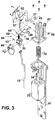
- drive unit 32 is a linear actuator formed by a linear hybrid stepper motor 32 that drives a threaded lead screw 34.
- the stepper motor in the linear actuator 32 turns a nut threaded onto the threaded lead screw 34.
- the lead screw 34 moves vertically up and down. Due to the stepping action and thread pitch, this vertical motion can be accurately controlled.
- a lead screw anchor 36 at the top end of the lead screw 34 is a lead screw anchor 36, preferably made of steel that is pinned to the end of the lead screw 34 with pin 43.
- the lead screw anchor 36 includes a shaft 37 having a horizontal axis.
- the shaft 37 is carried in a pair of bushings 45, 47 that slide vertically in slot 39.
- the shaft 37 is held in place with a C-clip 49.
- Retraction lever 38 tilts or pivots through a limited range.
- the retraction lever 38 extends from the exterior of the door thorough an opening in the surface of the door and into the interior of the door where the right side 40 of the retraction lever is in position to contact metal plate 42 attached to the vertical rod 16.
- a spring 60 pushes up on the left side 44 of the retraction lever 38 to ensure that the right side 40 contacts the metal plate 42.
- the retraction lever 38 initially tilts or pivots as it rotates around the shaft 37 in the lead screw anchor 36. During this initial pivoting action the vertical rods do not move. Instead, the left side 44 of the retraction lever 38 initially moves down a short distance until it reaches a limit.
- Limit switch 46 is mounted to the lead screw anchor and is located at the limit of travel of the pivoting retraction lever. As the left side 44 of the retraction lever reaches the limit, it contacts and actuates limit switch 46 to sense when the left side 44 has reached the predefined limit.
- the limit switch 46 is connected via a flexible ribbon connection to a control circuit in the form of a microcontroller mounted on a circuit board.
- Microcontroller circuit board includes a microcontroller, a Hall effect sensor, and a power system, as well as connectors for connecting to the limit switch, an external control system, and the linear actuator.
- the left side 44 of the retraction lever 38 contacts limit switch 46, the left side 44 is unable to move any further down and the right side 40 begins to move down.
- the lead screw anchor 36 and the retraction lever 38 continue to move down.
- the lead screw anchor 36 and the shaft 37 move down in slot 39.
- the retraction lever 38 rotates clockwise about the shaft 37. This drives the plate 42 and the upper vertical rod 16 down to unlatch the vertical rods.
- the top and bottom latches are known to be fully retracted.
- the housing 50 and the baseplate 41 are mounted to the surface of the door with the screws, as shown in Fig. 1 .
- the electric latch retraction device 30 is independently housed and separately mounted, its vertical location may vary relative to the location of the plate 42.
- the lead screw anchor can only move a limited distance relative to slot 39. Accordingly, there is a limit to how far the electric latch retraction device 30 may be installed vertically up or down relative to the plate 42.
- the lead screw anchor will have to move so far down before the left side of the retraction lever reaches its limit that there is no remaining travel to operate the vertical rods the required 12.7 mm (1 ⁇ 2").
- the electric latch retraction device 30 is installed very low relative to plate 42, the left side of the retraction lever will already be pushed down into contact with its lower limit and downward force may already be applied to plate 42. If the installation of the electric latch retraction device 30 is so low that the plate 42 is already partially driven down, the electric latch retraction device will be unable to move upwards to fully release the vertical rods to operate normally. They will always be in a partially actuated condition.
- the electric latch retraction device is provided with an auto adjustment feature.
- the auto adjustment feature relies partially upon the limit switch 46 and partially upon a Hall effect sensor 62 that monitors the position of the lead screw anchor 36 by detecting the vertical position of magnet 64 mounted to the lead screw anchor 36.
- the electronic latch retraction device is in the position shown in Figs. 1 , 2A and 2B .
- the lead screw anchor shaft 37 is at the top of the slot 39.
- Circuit board is provided with a microcontroller which initially drives the stepper motor 32 to drive threaded shaft 34 down.
- the lead screw anchor 36 also moves down and the retraction lever 38 pivots about moving shaft 37 in a counterclockwise direction until the left end 44 of the retraction lever contacts switch 46. At this point the counterclockwise rotation of the retraction lever stops and continued motion of the shaft 34 down pulls down on the plate 42 to retract the vertical rods and unlatch the vertical rod door latch.
- the microcontroller will detect this.
- the microcontroller is programmed at initial startup to detect this incorrect installation as described above where the limit switch 46 is already actuated.
- the Hall effect sensor 62 signals the microcontroller of the circuit board so that the vertical position of magnet 64 on the lead screw anchor 36 can be monitored.
- the electric latch retraction device must be able to drive the plate 42 downward at least one half inch after the limit switch 46 has been actuated.
- the microcontroller can detect the vertical position of the lead screw anchor 36 at the point when switch 46 is actuated and will know from that detection if one half inch of additional travel is available in slot 39. This is referred to as the auto adjustment feature of the present invention.
- the electronic latch retraction device 30 is provided with a separate escutcheon or cover 50.
- a wire 70 is provided for connection to the control system, which signals when the vertical rod latch system is to be actuated.
- the microcontroller circuit board is preferably fixed relative to the door while the limit switch 46, which is connected to the microcontroller circuit board, moves with the lead screw anchor 36..
- Spring 74 acts to drive the lead screw anchor 36 and lead screw 34 upwards to the upper limit when power is removed from the device so that it starts in the position seen in Fig. 2B .
Landscapes
- Business, Economics & Management (AREA)
- Emergency Management (AREA)
- Engineering & Computer Science (AREA)
- Mechanical Engineering (AREA)
- Physics & Mathematics (AREA)
- Electromagnetism (AREA)
- Lock And Its Accessories (AREA)
- Power-Operated Mechanisms For Wings (AREA)
- Structural Engineering (AREA)
Claims (15)
- Elektrische Riegeleinzugsvorrichtung (30) zum Antreiben eines vertikalen Stab-Türriegels, Folgendes umfassend:einen Dreheinzugshebel (38), mit einem Ende dazu angepasst, den vertikalen Stab-Türriegel anzutreiben;einen Grenzschalter (46), montiert zum Detektieren einer Position des Dreheinzugshebels (38) an einer Drehgrenze von dessen Bewegung und Bereitstellen eines Grenzsignals, das dies anzeigt;einen linearen Sensor, der ein Vertikalpositionssignal bereitstellt, das einer vertikalen Position des Dreheinzugshebels (38) entspricht;einen linearen Treiber (32), dazu montiert, den Dreheinzugshebel (38) vertikal anzutreiben:
eine Steuerschaltung, angeschlossen zum Antreiben des linearen Treibers (32) in vertikaler Bewegung und angeschlossen zum Empfangen des Grenzsignals und des vertikalen Positionssignals, wobei die Steuerschaltung den Dreheinzugshebel (38) in vertikaler Bewegung antreibt und Installationspositionsfehler der elektrischen Riegeleinzugsvorrichtung (30), relativ zum vertikalen Stab-Türriegel aus dem Grenzsignal und dem vertikalen Positionssignal detektiert durch Bestimmen, ob die elektrische Riegeleinzugsvorrichtung (30) in einer Position installiert wurde, die einen ausreichenden Bewegungsbereich des Einzugshebels (38) verhindert, wenn er durch den linearen Treiber (32) angetrieben wird, den vertikalen Stab-Türriegel korrekt zu operieren, wobei ein solcher Installationspositionsfehler identifiziert wird, indem die Steuerschaltung den linearen Treiber (32) antreibt, bis das Grenzsignal empfangen wird, und aus dem vertikalen Positionssignal zu bestimmen, dass ausreichend zusätzlicher Lauf verfügbar ist, sodass der lineare Treiber (32) den Einzugshebel (38) antreibt und den vertikalen Stab-Türriegel korrekt operiert. - Elektrische Riegeleinzugsvorrichtung (30) zum Antreiben eines vertikalen Stab-Türriegels nach Anspruch 1, worin der lineare Sensor ein Hall-Effekt-Sensor (62) ist.
- Elektrische Riegeleinzugsvorrichtung (30) zum Antreiben eines vertikalen Stab-Türriegels nach Anspruch 1, worin der vertikale Stab-Türriegel einen vertikalen Stab (16) enthält und eine Platte (42), die am vertikalen Stab (16) befestigt ist, und worin das Ende (40) des Dreheinzugshebels (38), der angepasst ist zum Antreiben des vertikalen Stab-Türriegels, die Platte (42) kontaktiert, wenn er den vertikalen Stab-Türriegel antreibt.
- Elektrische Riegeleinzugsvorrichtung (30) zum Antreiben eines vertikalen Stab-Türriegels nach Anspruch 1, worin:die elektrische Riegeleinzugsvorrichtung (30) außerdem eine Einzugshebelwelle (37) mit einer horizontalen Achse enthält, und sich der Einzugshebel (38) um die Einzugshebelwelle (37) dreht, sodass das Ende, das dazu angepasst ist, den vertikalen Stab-Türriegel relativ zur Einzugshebelwelle (37) vertikal aufwärts und abwärts anzutreiben, wenn sich der Einzugshebel (38) dreht;der lineare Treiber (32) angeschlossen ist, um die Welle (37) und den Einzugshebel (38) zusammen vertikal zu bewegen; undder Einzugshebel (38) an der Drehgrenze von dessen Bewegung ist, wenn der lineare Treiber den Einzugshebel und die Einzugswelle (37) antreibt, um den vertikalen Stab-Türriegel anzutreiben.
- Elektrische Riegeleinzugsvorrichtung (30) zum Antreiben eines vertikalen Stab-Türriegels nach Anspruch 4, außerdem eine Verankerung (36) enthaltend, angetrieben durch den vertikalen Treiber, und worin der Einzugshebel (38) und die Einzugshebelwelle (37) auf die Verankerung (36) montiert sind.
- Elektrische Riegeleinzugsvorrichtung (30) zum Antreiben eines vertikalen Stab-Türriegels nach Anspruch 4, worin die Einzugshebelwelle (37) innerhalb eines Schlitzes (39) vertikal gleitet.
- Elektrische Riegeleinzugsvorrichtung (30) zum Antreiben eines vertikalen Stab-Türriegels nach Anspruch 4, worin:der Einzugshebel (38) außerdem ein zweites Ende (44) gegenüber dem Ende enthält, das dazu angepasst ist, den vertikalen Stab-Türriegel anzutreiben; unddas zweite Ende (44) des Einzugshebels (38) sich abwärts bewegt, wenn das Ende, das dazu angepasst ist, den vertikalen Stab-Türriegel anzutreiben, sich aufwärts bewegt.
- Elektrische Riegeleinzugsvorrichtung (30) zum Antreiben eines vertikalen Stab-Türriegels nach Anspruch 1, worin die Steuerschaltung operiert, um einen Installationspositionsfehler der elektrischen Riegeleinzugsvorrichtung (30) zu detektieren, relativ zum vertikalen Stab-Türriegel, durch Bestimmen, ob die elektrische Riegeleinzugsvorrichtung (30) so installiert wurde, dass der Einzugshebel (38) an seiner Drehgrenze seiner Bewegung ist, wobei solch ein Installationspositionsfehler dadurch identifiziert wird, dass die Steuerschaltung detektiert, dass das Grenzsignal empfangen wird, bevor die Steuerschaltung den Einzugshebel (38) in vertikale Bewegung antreibt.
- Elektrische Riegeleinzugsvorrichtung (30) zum Antreiben eines vertikalen Stab-Türriegels nach Anspruch 1, worin die Steuerschaltung aus dem vertikalen Positionssignal bestimmt, dass auseichend zusätzlicher Lauf verfügbar ist, nachdem das Grenzsignal empfangen wird, durch Antreiben des linearen Treibers (32) und Bewegen des Einzugshebels (38) über die ausreichend zusätzliche Laufentfernung.
- Elektrische Riegeleinzugsvorrichtung (30) zum Antreiben eines vertikalen Stab-Türriegels nach Anspruch 1, worin die Steuerschaltung aus dem vertikalen Positionssignal bestimmt, dass ausreichend zusätzlicher Lauf verfügbar ist, nachdem das Grenzsignal empfangen wird, durch Bestimmen der Position des Einzugshebels (38) aus dem vertikalen Positionssignal, wenn das Grenzsignal empfangen wird, und Bestimmen, dass ausreichend zusätzliche Laufentfernung verfügbar ist, oder nicht, aus den vertikalen Positionssignalen, die an entsprechenden Grenzen des Laufs des Einzugshebels (38) empfangen werden.
- Elektrische Riegeleinzugsvorrichtung (30) zum Antreiben eines vertikalen Stab-Türriegels nach Anspruch 1, außerdem eine Einzugshebelfeder (74) enthaltend, angeschlossen zum Vorspannen des Einzugshebels (38), weg von der Position, die der Drehgrenze der Bewegung des Dreheinzugshebels (38) entspricht.
- Elektrische Riegeleinzugsvorrichtung (30) zum Antreiben eines vertikalen Stab-Türriegels nach Anspruch 11, worin:die Einzugshebelfeder (74) unzureichende Federkraft hat, um den vertikalen Stab-Türriegel zu operieren; unddie Steuerschaltung den linearen Treiber (32) antreibt, um den Einzugshebel (38) gegen die Vorspannkraft der Einzugshebelfeder (74) zu drehen und den Einzugshebel (38) auf seine Drehgrenze der Bewegung zu bewegen.
- Elektrische Riegeleinzugsvorrichtung (30) zum Antreiben eines vertikalen Stab-Türriegels nach Anspruch 1, worin der lineare Treiber einen linearen hybriden Steppermotor (32) enthält, der eine Gewinde-Leitspindel (34) antreibt.
- Elektrische Riegeleinzugsvorrichtung (30) zum Antreiben eines vertikalen Stab-Türriegels nach Anspruch 1, worin die Steuerschaltung einen Microcontroller enthält, der auf eine Platine montiert ist, und der lineare Sensor ein Hall-Effekt-Sensor (62) ist, der auf die Platine montiert ist.
- Elektrische Riegeleinzugsvorrichtung (30) zum Antreiben eines vertikalen Stab-Türriegels nach Anspruch 1, außerdem eine Basisplatte (41) für die elektrische Riegeleinzugsvorrichtung und ein Gehäuse (50) für die elektrische Riegeleinzugseinrichtung enthaltend, wobei das Ende des Dreheinzugshebels (38) dazu angepasst ist, den vertikalen Stab-Türriegel sich von der Basisplatte (41) nach außen erstreckend anzutreiben, um in den vertikalen Stab-Türriegel einzugreifen.
Applications Claiming Priority (2)
| Application Number | Priority Date | Filing Date | Title |
|---|---|---|---|
| US201261737475P | 2012-12-14 | 2012-12-14 | |
| PCT/US2013/074593 WO2014093586A1 (en) | 2012-12-14 | 2013-12-12 | Electric latch retraction device for vertical rod door latches |
Publications (3)
| Publication Number | Publication Date |
|---|---|
| EP2931996A1 EP2931996A1 (de) | 2015-10-21 |
| EP2931996A4 EP2931996A4 (de) | 2016-10-19 |
| EP2931996B1 true EP2931996B1 (de) | 2018-07-11 |
Family
ID=50934943
Family Applications (1)
| Application Number | Title | Priority Date | Filing Date |
|---|---|---|---|
| EP13862171.9A Not-in-force EP2931996B1 (de) | 2012-12-14 | 2013-12-12 | Elektrische riegeleinzugsvorrichtung für türriegel in form vertikaler stangen |
Country Status (10)
| Country | Link |
|---|---|
| US (1) | US9822552B2 (de) |
| EP (1) | EP2931996B1 (de) |
| KR (1) | KR20150096402A (de) |
| CN (1) | CN104870733B (de) |
| AU (1) | AU2013359253B2 (de) |
| CA (1) | CA2892809C (de) |
| IL (1) | IL239160B (de) |
| MX (1) | MX362659B (de) |
| TW (1) | TW201439419A (de) |
| WO (1) | WO2014093586A1 (de) |
Families Citing this family (23)
| Publication number | Priority date | Publication date | Assignee | Title |
|---|---|---|---|---|
| DE202014002413U1 (de) * | 2014-03-18 | 2015-06-22 | Gretsch-Unitas GmbH Baubeschläge | Türanordnung |
| US10968661B2 (en) | 2016-08-17 | 2021-04-06 | Amesbury Group, Inc. | Locking system having an electronic deadbolt |
| US11208832B2 (en) | 2016-08-30 | 2021-12-28 | Sargent Manufacturing Company | Mortise lock with multi-point latch system |
| WO2018044361A1 (en) | 2016-08-30 | 2018-03-08 | Sargent Manufacturing Company | Mortise lock with multi-point latch system |
| US11111698B2 (en) | 2016-12-05 | 2021-09-07 | Endura Products, Llc | Multipoint lock |
| US10876324B2 (en) | 2017-01-19 | 2020-12-29 | Endura Products, Llc | Multipoint lock |
| US10662675B2 (en) | 2017-04-18 | 2020-05-26 | Amesbury Group, Inc. | Modular electronic deadbolt systems |
| US10808424B2 (en) * | 2017-05-01 | 2020-10-20 | Amesbury Group, Inc. | Modular multi-point lock |
| US11066850B2 (en) | 2017-07-25 | 2021-07-20 | Amesbury Group, Inc | Access handle for sliding doors |
| US11851913B2 (en) | 2017-12-11 | 2023-12-26 | Sargent Manufacturing Company | Hook bolt for door lock |
| CA3036398A1 (en) | 2018-03-12 | 2019-09-12 | Amesbury Group, Inc. | Electronic deadbolt systems |
| US11306512B2 (en) * | 2018-08-01 | 2022-04-19 | Schlage Lock Company Llc | Exit device with remote trim input |
| US11834866B2 (en) | 2018-11-06 | 2023-12-05 | Amesbury Group, Inc. | Flexible coupling for electronic deadbolt systems |
| US11661771B2 (en) | 2018-11-13 | 2023-05-30 | Amesbury Group, Inc. | Electronic drive for door locks |
| WO2020131869A1 (en) | 2018-12-21 | 2020-06-25 | Sargent Manufacturing Company | Side latch exit device |
| US11746565B2 (en) | 2019-05-01 | 2023-09-05 | Endura Products, Llc | Multipoint lock assembly for a swinging door panel |
| CA3087386A1 (en) | 2019-07-18 | 2021-01-18 | Endura Products, Llc | Methods of operating a lock |
| DE102019125988A1 (de) * | 2019-09-26 | 2021-04-01 | Solarlux Gmbh | Faltanlage |
| CA3119092A1 (en) | 2020-05-19 | 2021-11-19 | Dormakaba Usa Inc. | Assembly for exit device |
| US12264506B2 (en) * | 2020-10-09 | 2025-04-01 | Assa Abloy Access And Egress Hardware Group, Inc. | Exit device rod adjustment |
| TWI745191B (zh) * | 2020-12-09 | 2021-11-01 | 台灣福興工業股份有限公司 | 電子鎖及其離合機構 |
| CN113338719A (zh) * | 2021-08-05 | 2021-09-03 | 恒银金融科技股份有限公司 | 一种用于自助设备远程授权的圆片锁互锁装置 |
| CN115263093B (zh) * | 2022-08-04 | 2025-07-29 | 广东逸家安防科技有限公司 | 一种电动锁 |
Family Cites Families (27)
| Publication number | Priority date | Publication date | Assignee | Title |
|---|---|---|---|---|
| JPS5991274A (ja) * | 1982-11-16 | 1984-05-25 | 日産自動車株式会社 | シリンダ錠の抜き取り検知装置 |
| DE4401971C2 (de) * | 1994-01-26 | 1997-01-02 | Josef Geiger | Motorbetriebenes Türschloß |
| US5684457A (en) * | 1995-06-01 | 1997-11-04 | C&M Technology, Inc. | Tamper indication system for combination locks |
| US6259352B1 (en) * | 1998-03-02 | 2001-07-10 | Leon Yulkowski | Door lock system |
| US6655180B2 (en) * | 2001-07-31 | 2003-12-02 | Security People, Inc. | Locker lock with adjustable bolt |
| DE10139675A1 (de) | 2001-08-11 | 2003-02-20 | Winkhaus Fa August | Verriegelungseinrichtung |
| US20040011347A1 (en) | 2002-02-20 | 2004-01-22 | James Ramsey | Oven door latch assembly |
| US6598439B1 (en) * | 2002-10-15 | 2003-07-29 | Ez Trend Technology Co., Ltd. | Lock-and-alarm assembly |
| US7321291B2 (en) * | 2004-10-26 | 2008-01-22 | Current Technologies, Llc | Power line communications system and method of operating the same |
| DE102004024704A1 (de) * | 2004-05-19 | 2005-12-15 | Robert Bosch Gmbh | Vorrichtung zur Erkennung eines Einbaufehlers bei gegenüberliegenden Satellitensensoren in einem Fahrzeug |
| US7385504B2 (en) * | 2005-03-31 | 2008-06-10 | Cantaloupe Systems, Inc. | Vending machine door monitoring system |
| US7484777B2 (en) | 2006-06-30 | 2009-02-03 | Sargent Manufacturing Company | Electronic push retraction exit device |
| CN200949401Y (zh) * | 2006-09-11 | 2007-09-19 | 刘恩 | 电控防盗门 |
| DE102006049557A1 (de) * | 2006-10-20 | 2008-04-24 | Franz Xaver Meiller Fahrzeug- Und Maschinenfabrik - Gmbh & Co Kg | Riegelelement zur Sicherung eines Pendelzapfens einer Kippbrückenbordwand in einer Pendelzapfenaufnahme an einem Bordwandhalteelement |
| FR2907483A1 (fr) * | 2006-10-23 | 2008-04-25 | Croisee D S Sa | Dispositif de blocage en position fermee d'un vantail coulissant dans un dormant |
| US7748757B2 (en) * | 2008-09-17 | 2010-07-06 | I-Tek Metal Mfg. Co. Ltd. | Connecting device for concealed-type top or bottom latch for panic exit door lock |
| US20120169071A1 (en) | 2009-04-23 | 2012-07-05 | Labarre Andre | Motorized system for latching and unlatching casement windows |
| US8495836B2 (en) * | 2009-08-27 | 2013-07-30 | Sargent Manufacturing Company | Door hardware drive mechanism with sensor |
| US8911056B2 (en) * | 2010-03-24 | 2014-12-16 | Seiko Epson Corporation | Electronic instrument and management method |
| US8653954B2 (en) * | 2011-04-26 | 2014-02-18 | General Motors Llc | Systems and methods for detecting an error in the installation of an electrical component |
| CN202064730U (zh) * | 2011-04-29 | 2011-12-07 | 刘恩 | 一种转体舌智能防盗锁 |
| KR101594823B1 (ko) * | 2011-11-03 | 2016-02-17 | 사전트 매뉴팩츄어링 캄파니 | 통합 도어 위치센서가 구비된 도어 록 |
| US20130181825A1 (en) * | 2012-01-13 | 2013-07-18 | Jerry Johnson | Guardian Warning System |
| TWI474953B (zh) * | 2012-05-23 | 2015-03-01 | 台灣積層工業股份有限公司 | Packaging bags with external stickers |
| US8941506B2 (en) * | 2012-10-05 | 2015-01-27 | General Motors Llc | Methods and systems for identifying wiring of a telematics system |
| TWI620135B (zh) * | 2013-12-23 | 2018-04-01 | 財團法人工業技術研究院 | 電子貨架標籤控制系統、安裝方法及更新方法 |
| CA2883972A1 (en) * | 2014-03-03 | 2015-09-03 | Berntsen Int, Inc. | Advanced system for navigating between, locating and monitoring underground assets |
-
2013
- 2013-12-12 MX MX2015007536A patent/MX362659B/es active IP Right Grant
- 2013-12-12 EP EP13862171.9A patent/EP2931996B1/de not_active Not-in-force
- 2013-12-12 WO PCT/US2013/074593 patent/WO2014093586A1/en not_active Ceased
- 2013-12-12 KR KR1020157015644A patent/KR20150096402A/ko not_active Withdrawn
- 2013-12-12 US US14/648,007 patent/US9822552B2/en active Active
- 2013-12-12 CN CN201380064985.8A patent/CN104870733B/zh active Active
- 2013-12-12 CA CA2892809A patent/CA2892809C/en active Active
- 2013-12-12 AU AU2013359253A patent/AU2013359253B2/en active Active
- 2013-12-13 TW TW102146068A patent/TW201439419A/zh unknown
-
2015
- 2015-06-03 IL IL239160A patent/IL239160B/en active IP Right Grant
Non-Patent Citations (1)
| Title |
|---|
| None * |
Also Published As
| Publication number | Publication date |
|---|---|
| IL239160B (en) | 2018-12-31 |
| CN104870733A (zh) | 2015-08-26 |
| KR20150096402A (ko) | 2015-08-24 |
| IL239160A0 (en) | 2015-07-30 |
| EP2931996A4 (de) | 2016-10-19 |
| EP2931996A1 (de) | 2015-10-21 |
| CA2892809A1 (en) | 2014-06-19 |
| AU2013359253B2 (en) | 2017-07-06 |
| MX362659B (es) | 2019-01-31 |
| AU2013359253A1 (en) | 2015-06-18 |
| TW201439419A (zh) | 2014-10-16 |
| MX2015007536A (es) | 2015-10-14 |
| US9822552B2 (en) | 2017-11-21 |
| US20150308155A1 (en) | 2015-10-29 |
| WO2014093586A1 (en) | 2014-06-19 |
| CA2892809C (en) | 2020-10-13 |
| CN104870733B (zh) | 2017-06-09 |
Similar Documents
| Publication | Publication Date | Title |
|---|---|---|
| EP2931996B1 (de) | Elektrische riegeleinzugsvorrichtung für türriegel in form vertikaler stangen | |
| US10808424B2 (en) | Modular multi-point lock | |
| CN1766268B (zh) | 插芯锁装置 | |
| EP2470736B1 (de) | Türen-hardwareantriebsmechanismus mit sensor | |
| CA3010376C (en) | A door strike having a kicker and an adjustable dead latch release | |
| EP2526248B1 (de) | Schiebetürverschluss mit doppelter öffnungsmöglichkeit | |
| DK2525025T3 (en) | Electronic unit for a blocking device and locking system | |
| JPH0249883A (ja) | 扉,窓等の錠止装置 | |
| EP2847401B1 (de) | Schloss | |
| WO2002090694A1 (en) | Swinging elevator hatchway door interlock | |
| KR100676551B1 (ko) | 양방향 도어용 개선된 잠금 장치 | |
| WO2026044328A1 (en) | Lock body | |
| US20190360235A1 (en) | Easy install exit device | |
| RU2796446C1 (ru) | Замок дверной с электроприводом | |
| WO2026044329A1 (en) | Lock body | |
| WO2026044331A1 (en) | Key actuator for a lock | |
| EP1988238B1 (de) | Sicherheits- und Zugangskontrollsystem für einen Telekommunikationsschrank | |
| HK1117812B (en) | Safety lock for elevator landing door | |
| HK1117812A1 (en) | Safety lock for elevator landing door | |
| NZ610372A (en) | A lock |
Legal Events
| Date | Code | Title | Description |
|---|---|---|---|
| PUAI | Public reference made under article 153(3) epc to a published international application that has entered the european phase |
Free format text: ORIGINAL CODE: 0009012 |
|
| 17P | Request for examination filed |
Effective date: 20150710 |
|
| AK | Designated contracting states |
Kind code of ref document: A1 Designated state(s): AL AT BE BG CH CY CZ DE DK EE ES FI FR GB GR HR HU IE IS IT LI LT LU LV MC MK MT NL NO PL PT RO RS SE SI SK SM TR |
|
| AX | Request for extension of the european patent |
Extension state: BA ME |
|
| RIN1 | Information on inventor provided before grant (corrected) |
Inventor name: HILL, CHRISTOPHER, C. Inventor name: ELLER, DARREN, C. Inventor name: GERACI, ANDREW |
|
| RIN1 | Information on inventor provided before grant (corrected) |
Inventor name: GERACI, ANDREW Inventor name: ELLER, DARREN, C. Inventor name: HILL, CHRISTOPHER, C. |
|
| DAX | Request for extension of the european patent (deleted) | ||
| A4 | Supplementary search report drawn up and despatched |
Effective date: 20160920 |
|
| RIC1 | Information provided on ipc code assigned before grant |
Ipc: E05B 63/20 20060101ALN20160914BHEP Ipc: E05B 63/06 20060101AFI20160914BHEP Ipc: E05B 47/02 20060101ALI20160914BHEP Ipc: E05C 9/04 20060101ALI20160914BHEP Ipc: E05B 47/00 20060101ALN20160914BHEP Ipc: E05B 65/10 20060101ALI20160914BHEP |
|
| REG | Reference to a national code |
Ref country code: DE Ref legal event code: R079 Ref document number: 602013040267 Country of ref document: DE Free format text: PREVIOUS MAIN CLASS: E05B0063060000 Ipc: E05B0047020000 |
|
| GRAP | Despatch of communication of intention to grant a patent |
Free format text: ORIGINAL CODE: EPIDOSNIGR1 |
|
| RIC1 | Information provided on ipc code assigned before grant |
Ipc: E05B 63/20 20060101ALN20180105BHEP Ipc: E05B 47/02 20060101AFI20180105BHEP Ipc: E05C 9/04 20060101ALI20180105BHEP Ipc: E05B 65/10 20060101ALI20180105BHEP Ipc: E05B 47/00 20060101ALI20180105BHEP |
|
| INTG | Intention to grant announced |
Effective date: 20180209 |
|
| GRAS | Grant fee paid |
Free format text: ORIGINAL CODE: EPIDOSNIGR3 |
|
| GRAA | (expected) grant |
Free format text: ORIGINAL CODE: 0009210 |
|
| AK | Designated contracting states |
Kind code of ref document: B1 Designated state(s): AL AT BE BG CH CY CZ DE DK EE ES FI FR GB GR HR HU IE IS IT LI LT LU LV MC MK MT NL NO PL PT RO RS SE SI SK SM TR |
|
| REG | Reference to a national code |
Ref country code: GB Ref legal event code: FG4D |
|
| REG | Reference to a national code |
Ref country code: CH Ref legal event code: EP |
|
| REG | Reference to a national code |
Ref country code: AT Ref legal event code: REF Ref document number: 1017044 Country of ref document: AT Kind code of ref document: T Effective date: 20180715 |
|
| REG | Reference to a national code |
Ref country code: IE Ref legal event code: FG4D |
|
| REG | Reference to a national code |
Ref country code: DE Ref legal event code: R096 Ref document number: 602013040267 Country of ref document: DE |
|
| REG | Reference to a national code |
Ref country code: NL Ref legal event code: MP Effective date: 20180711 |
|
| REG | Reference to a national code |
Ref country code: LT Ref legal event code: MG4D |
|
| REG | Reference to a national code |
Ref country code: AT Ref legal event code: MK05 Ref document number: 1017044 Country of ref document: AT Kind code of ref document: T Effective date: 20180711 |
|
| PG25 | Lapsed in a contracting state [announced via postgrant information from national office to epo] |
Ref country code: NL Free format text: LAPSE BECAUSE OF FAILURE TO SUBMIT A TRANSLATION OF THE DESCRIPTION OR TO PAY THE FEE WITHIN THE PRESCRIBED TIME-LIMIT Effective date: 20180711 |
|
| PG25 | Lapsed in a contracting state [announced via postgrant information from national office to epo] |
Ref country code: GR Free format text: LAPSE BECAUSE OF FAILURE TO SUBMIT A TRANSLATION OF THE DESCRIPTION OR TO PAY THE FEE WITHIN THE PRESCRIBED TIME-LIMIT Effective date: 20181012 Ref country code: NO Free format text: LAPSE BECAUSE OF FAILURE TO SUBMIT A TRANSLATION OF THE DESCRIPTION OR TO PAY THE FEE WITHIN THE PRESCRIBED TIME-LIMIT Effective date: 20181011 Ref country code: SE Free format text: LAPSE BECAUSE OF FAILURE TO SUBMIT A TRANSLATION OF THE DESCRIPTION OR TO PAY THE FEE WITHIN THE PRESCRIBED TIME-LIMIT Effective date: 20180711 Ref country code: BG Free format text: LAPSE BECAUSE OF FAILURE TO SUBMIT A TRANSLATION OF THE DESCRIPTION OR TO PAY THE FEE WITHIN THE PRESCRIBED TIME-LIMIT Effective date: 20181011 Ref country code: AT Free format text: LAPSE BECAUSE OF FAILURE TO SUBMIT A TRANSLATION OF THE DESCRIPTION OR TO PAY THE FEE WITHIN THE PRESCRIBED TIME-LIMIT Effective date: 20180711 Ref country code: LT Free format text: LAPSE BECAUSE OF FAILURE TO SUBMIT A TRANSLATION OF THE DESCRIPTION OR TO PAY THE FEE WITHIN THE PRESCRIBED TIME-LIMIT Effective date: 20180711 Ref country code: PL Free format text: LAPSE BECAUSE OF FAILURE TO SUBMIT A TRANSLATION OF THE DESCRIPTION OR TO PAY THE FEE WITHIN THE PRESCRIBED TIME-LIMIT Effective date: 20180711 Ref country code: IS Free format text: LAPSE BECAUSE OF FAILURE TO SUBMIT A TRANSLATION OF THE DESCRIPTION OR TO PAY THE FEE WITHIN THE PRESCRIBED TIME-LIMIT Effective date: 20181111 Ref country code: FI Free format text: LAPSE BECAUSE OF FAILURE TO SUBMIT A TRANSLATION OF THE DESCRIPTION OR TO PAY THE FEE WITHIN THE PRESCRIBED TIME-LIMIT Effective date: 20180711 Ref country code: RS Free format text: LAPSE BECAUSE OF FAILURE TO SUBMIT A TRANSLATION OF THE DESCRIPTION OR TO PAY THE FEE WITHIN THE PRESCRIBED TIME-LIMIT Effective date: 20180711 |
|
| PG25 | Lapsed in a contracting state [announced via postgrant information from national office to epo] |
Ref country code: ES Free format text: LAPSE BECAUSE OF FAILURE TO SUBMIT A TRANSLATION OF THE DESCRIPTION OR TO PAY THE FEE WITHIN THE PRESCRIBED TIME-LIMIT Effective date: 20180711 Ref country code: HR Free format text: LAPSE BECAUSE OF FAILURE TO SUBMIT A TRANSLATION OF THE DESCRIPTION OR TO PAY THE FEE WITHIN THE PRESCRIBED TIME-LIMIT Effective date: 20180711 Ref country code: AL Free format text: LAPSE BECAUSE OF FAILURE TO SUBMIT A TRANSLATION OF THE DESCRIPTION OR TO PAY THE FEE WITHIN THE PRESCRIBED TIME-LIMIT Effective date: 20180711 Ref country code: LV Free format text: LAPSE BECAUSE OF FAILURE TO SUBMIT A TRANSLATION OF THE DESCRIPTION OR TO PAY THE FEE WITHIN THE PRESCRIBED TIME-LIMIT Effective date: 20180711 |
|
| REG | Reference to a national code |
Ref country code: DE Ref legal event code: R097 Ref document number: 602013040267 Country of ref document: DE |
|
| PG25 | Lapsed in a contracting state [announced via postgrant information from national office to epo] |
Ref country code: RO Free format text: LAPSE BECAUSE OF FAILURE TO SUBMIT A TRANSLATION OF THE DESCRIPTION OR TO PAY THE FEE WITHIN THE PRESCRIBED TIME-LIMIT Effective date: 20180711 Ref country code: EE Free format text: LAPSE BECAUSE OF FAILURE TO SUBMIT A TRANSLATION OF THE DESCRIPTION OR TO PAY THE FEE WITHIN THE PRESCRIBED TIME-LIMIT Effective date: 20180711 Ref country code: IT Free format text: LAPSE BECAUSE OF FAILURE TO SUBMIT A TRANSLATION OF THE DESCRIPTION OR TO PAY THE FEE WITHIN THE PRESCRIBED TIME-LIMIT Effective date: 20180711 Ref country code: CZ Free format text: LAPSE BECAUSE OF FAILURE TO SUBMIT A TRANSLATION OF THE DESCRIPTION OR TO PAY THE FEE WITHIN THE PRESCRIBED TIME-LIMIT Effective date: 20180711 |
|
| PLBE | No opposition filed within time limit |
Free format text: ORIGINAL CODE: 0009261 |
|
| STAA | Information on the status of an ep patent application or granted ep patent |
Free format text: STATUS: NO OPPOSITION FILED WITHIN TIME LIMIT |
|
| PG25 | Lapsed in a contracting state [announced via postgrant information from national office to epo] |
Ref country code: SK Free format text: LAPSE BECAUSE OF FAILURE TO SUBMIT A TRANSLATION OF THE DESCRIPTION OR TO PAY THE FEE WITHIN THE PRESCRIBED TIME-LIMIT Effective date: 20180711 Ref country code: SM Free format text: LAPSE BECAUSE OF FAILURE TO SUBMIT A TRANSLATION OF THE DESCRIPTION OR TO PAY THE FEE WITHIN THE PRESCRIBED TIME-LIMIT Effective date: 20180711 Ref country code: DK Free format text: LAPSE BECAUSE OF FAILURE TO SUBMIT A TRANSLATION OF THE DESCRIPTION OR TO PAY THE FEE WITHIN THE PRESCRIBED TIME-LIMIT Effective date: 20180711 |
|
| 26N | No opposition filed |
Effective date: 20190412 |
|
| REG | Reference to a national code |
Ref country code: DE Ref legal event code: R119 Ref document number: 602013040267 Country of ref document: DE |
|
| REG | Reference to a national code |
Ref country code: CH Ref legal event code: PL |
|
| GBPC | Gb: european patent ceased through non-payment of renewal fee |
Effective date: 20181212 |
|
| PG25 | Lapsed in a contracting state [announced via postgrant information from national office to epo] |
Ref country code: MC Free format text: LAPSE BECAUSE OF FAILURE TO SUBMIT A TRANSLATION OF THE DESCRIPTION OR TO PAY THE FEE WITHIN THE PRESCRIBED TIME-LIMIT Effective date: 20180711 Ref country code: LU Free format text: LAPSE BECAUSE OF NON-PAYMENT OF DUE FEES Effective date: 20181212 Ref country code: SI Free format text: LAPSE BECAUSE OF FAILURE TO SUBMIT A TRANSLATION OF THE DESCRIPTION OR TO PAY THE FEE WITHIN THE PRESCRIBED TIME-LIMIT Effective date: 20180711 |
|
| REG | Reference to a national code |
Ref country code: IE Ref legal event code: MM4A |
|
| REG | Reference to a national code |
Ref country code: BE Ref legal event code: MM Effective date: 20181231 |
|
| PG25 | Lapsed in a contracting state [announced via postgrant information from national office to epo] |
Ref country code: DE Free format text: LAPSE BECAUSE OF NON-PAYMENT OF DUE FEES Effective date: 20190702 Ref country code: IE Free format text: LAPSE BECAUSE OF NON-PAYMENT OF DUE FEES Effective date: 20181212 Ref country code: FR Free format text: LAPSE BECAUSE OF NON-PAYMENT OF DUE FEES Effective date: 20181231 |
|
| PG25 | Lapsed in a contracting state [announced via postgrant information from national office to epo] |
Ref country code: BE Free format text: LAPSE BECAUSE OF NON-PAYMENT OF DUE FEES Effective date: 20181231 |
|
| PG25 | Lapsed in a contracting state [announced via postgrant information from national office to epo] |
Ref country code: GB Free format text: LAPSE BECAUSE OF NON-PAYMENT OF DUE FEES Effective date: 20181212 Ref country code: CH Free format text: LAPSE BECAUSE OF NON-PAYMENT OF DUE FEES Effective date: 20181231 Ref country code: LI Free format text: LAPSE BECAUSE OF NON-PAYMENT OF DUE FEES Effective date: 20181231 |
|
| PG25 | Lapsed in a contracting state [announced via postgrant information from national office to epo] |
Ref country code: MT Free format text: LAPSE BECAUSE OF NON-PAYMENT OF DUE FEES Effective date: 20181212 |
|
| PG25 | Lapsed in a contracting state [announced via postgrant information from national office to epo] |
Ref country code: TR Free format text: LAPSE BECAUSE OF FAILURE TO SUBMIT A TRANSLATION OF THE DESCRIPTION OR TO PAY THE FEE WITHIN THE PRESCRIBED TIME-LIMIT Effective date: 20180711 |
|
| PG25 | Lapsed in a contracting state [announced via postgrant information from national office to epo] |
Ref country code: PT Free format text: LAPSE BECAUSE OF FAILURE TO SUBMIT A TRANSLATION OF THE DESCRIPTION OR TO PAY THE FEE WITHIN THE PRESCRIBED TIME-LIMIT Effective date: 20180711 |
|
| PG25 | Lapsed in a contracting state [announced via postgrant information from national office to epo] |
Ref country code: CY Free format text: LAPSE BECAUSE OF FAILURE TO SUBMIT A TRANSLATION OF THE DESCRIPTION OR TO PAY THE FEE WITHIN THE PRESCRIBED TIME-LIMIT Effective date: 20180711 Ref country code: MK Free format text: LAPSE BECAUSE OF NON-PAYMENT OF DUE FEES Effective date: 20180711 Ref country code: HU Free format text: LAPSE BECAUSE OF FAILURE TO SUBMIT A TRANSLATION OF THE DESCRIPTION OR TO PAY THE FEE WITHIN THE PRESCRIBED TIME-LIMIT; INVALID AB INITIO Effective date: 20131212 |