EP2931979B1 - Mischwerkzeug für die behandlung eines erdbereiches - Google Patents
Mischwerkzeug für die behandlung eines erdbereiches Download PDFInfo
- Publication number
- EP2931979B1 EP2931979B1 EP13815055.2A EP13815055A EP2931979B1 EP 2931979 B1 EP2931979 B1 EP 2931979B1 EP 13815055 A EP13815055 A EP 13815055A EP 2931979 B1 EP2931979 B1 EP 2931979B1
- Authority
- EP
- European Patent Office
- Prior art keywords
- rotary shaft
- tubular element
- soil
- coupling system
- treatment device
- Prior art date
- Legal status (The legal status is an assumption and is not a legal conclusion. Google has not performed a legal analysis and makes no representation as to the accuracy of the status listed.)
- Active
Links
Images


Classifications
-
- B—PERFORMING OPERATIONS; TRANSPORTING
- B09—DISPOSAL OF SOLID WASTE; RECLAMATION OF CONTAMINATED SOIL
- B09C—RECLAMATION OF CONTAMINATED SOIL
- B09C1/00—Reclamation of contaminated soil
- B09C1/02—Extraction using liquids, e.g. washing, leaching, flotation
-
- E—FIXED CONSTRUCTIONS
- E02—HYDRAULIC ENGINEERING; FOUNDATIONS; SOIL SHIFTING
- E02D—FOUNDATIONS; EXCAVATIONS; EMBANKMENTS; UNDERGROUND OR UNDERWATER STRUCTURES
- E02D5/00—Bulkheads, piles, or other structural elements specially adapted to foundation engineering
- E02D5/22—Piles
- E02D5/34—Concrete or concrete-like piles cast in position ; Apparatus for making same
- E02D5/46—Concrete or concrete-like piles cast in position ; Apparatus for making same making in situ by forcing bonding agents into gravel fillings or the soil
-
- B—PERFORMING OPERATIONS; TRANSPORTING
- B01—PHYSICAL OR CHEMICAL PROCESSES OR APPARATUS IN GENERAL
- B01F—MIXING, e.g. DISSOLVING, EMULSIFYING OR DISPERSING
- B01F27/00—Mixers with rotary stirring devices in fixed receptacles; Kneaders
- B01F27/80—Mixers with rotary stirring devices in fixed receptacles; Kneaders with stirrers rotating about a substantially vertical axis
-
- B—PERFORMING OPERATIONS; TRANSPORTING
- B09—DISPOSAL OF SOLID WASTE; RECLAMATION OF CONTAMINATED SOIL
- B09C—RECLAMATION OF CONTAMINATED SOIL
- B09C1/00—Reclamation of contaminated soil
- B09C1/08—Reclamation of contaminated soil chemically
-
- E—FIXED CONSTRUCTIONS
- E02—HYDRAULIC ENGINEERING; FOUNDATIONS; SOIL SHIFTING
- E02D—FOUNDATIONS; EXCAVATIONS; EMBANKMENTS; UNDERGROUND OR UNDERWATER STRUCTURES
- E02D3/00—Improving or preserving soil or rock, e.g. preserving permafrost soil
-
- B—PERFORMING OPERATIONS; TRANSPORTING
- B09—DISPOSAL OF SOLID WASTE; RECLAMATION OF CONTAMINATED SOIL
- B09C—RECLAMATION OF CONTAMINATED SOIL
- B09C2101/00—In situ
Definitions
- the present invention relates to the field of the treatment of portions of soil in particular to improve the mechanical, physical and / or chemical properties.
- the present invention relates to a device for treating a portion of soil (hereinafter treatment device) by mixing said soil with another material, and a soil treatment method carried out using this device .
- the present invention more specifically relates to a type of treatment device comprising a rotary shaft extending along a main axis and having an upper end facing upstream and a lower end facing downstream, at least one fixed deployable mixer tool. to the rotary shaft near its lower end, and a longitudinal pipe for injecting a fluid near the mixing tool.
- the document EP 1 878 833 describes a treatment device of the aforementioned type.
- a first drilling step is necessary to produce a tubular cavity in the soil.
- This first step is performed using a separate drilling tool, which is extracted from the borehole before the introduction of the treatment device.
- the tubular cavity may take the form of a simple borehole.
- Another solution is to introduce a casing into the soil and then drill inside said casing to make the cavity.
- the treatment device is inserted inside the cavity and moved inside thereof until its lower end penetrates into the portion of soil to be treated.
- the mixing tool is then deployed, the shaft is rotated and a fluid is injected simultaneously into the soil portion by the lower end of the shaft.
- the first stage of realization of the tubular cavity mobilizes drilling tools and requires time which, in fact, is not used to the actual soil treatment operation.
- the withdrawal of this tube is a third step in addition to the previous two, further reducing the productivity of the treatment process.
- An object of the invention is to provide a device and a method of treatment which substantially overcome the disadvantages mentioned above.
- a treatment device of the aforementioned type by virtue of the fact that it further comprises a drilling tool located at the lower end of the shaft, an external tubular element extending along an axis parallel to the main axis of the rotary shaft, the rotary shaft being disposed inside said tubular element, and a coupling system between the rotary shaft and the tubular element, said coupling system being, in a first configuration, suitable to fasten the tubular element and the rotary shaft in rotation around the main axis, in at least one direction of rotation, and to join the tubular element and the rotary shaft in translation along the main axis, at least in the downstream direction, and said coupling system being, in a second configuration, capable of releasing said rotational and translational movements.
- the device according to the invention is both a drilling device and a device for mixing the soil with one or more other materials.
- the drilling tool is provided directly at the lower end of the rotary shaft, so that a borehole can be made as the device progresses. Thanks to the coupling system between the rotary shaft and the tubular element, the latter can, in addition, be introduced into the ground together with the rotary shaft, during the drilling operation.
- the displacement of the treatment device in rotation and in translation in the ground can be obtained by means of a device with a single driving head.
- the drive of the rotary shaft in rotation and in translation is transmitted to the tubular element by the coupling system, in its first configuration, so that the two elements move together.
- the mixing tool housed in the tubular element when the coupling system is in its first configuration, can then be extracted from the tubular element and introduced into the portion of soil to be treated.
- the treatment device is then adapted to carry out an operation generally called "soil mixing" which consists of destructuring the soil then mixing the destructured soil with a fluid in order to modify the characteristics of the soil.
- This fluid may be for example a reactive liquid, a slurry intended to set, in particular a hydraulic binder, or a gas carrying solid particles.
- the mixing tool destroys the soil and then mixes it with a chemical reagent.
- any rise of materials, including pollutants, is through a passage located between the rotary shaft and the outer tubular element, the soil located around the outer tubular element being thus protected .
- the deployable mixer tool comprises at least one deployable mixer arm attached to the lower end of the rotary shaft and extending laterally relative to the longitudinal direction of the shaft, said arm having a position deployed and a retracted position, such that, in the deployed position, the span of the mixing tool is greater than the diameter external of the tubular element to allow the treatment of the ground portion by rotation of the shaft, and in the retracted position, the mixing tool is adapted to be inserted into the tubular element.
- the mixing tool further comprises spring means able to cause the deployment of the mixing arm out of the tubular element and to allow its return to the retracted position during the insertion of the lower part of the shaft into the tubular element.
- the deployed position is then the natural position of the retractable arm, that is to say that in the absence of any external constraint, the arm extends laterally with respect to the longitudinal direction of the shaft being separated from the latter thanks to the means springs.
- the mixing tool is inserted into the tubular element, it is understood that the inner wall of the tubular element acts on the arm to bring it into retracted position, that is to say towards the shaft.
- an axial direction is a direction parallel to the main axis of the rotary shaft.
- a radial direction is a direction perpendicular to the main axis and intersecting this axis.
- the adjectives and adverbs axial, radial, axially and radially are used with reference to the aforementioned axial and radial directions.
- an axial plane is a plane containing the main axis of the rotary shaft and a radial plane is a plane perpendicular to this axis.
- an axial section is a section defined in an axial plane, and a radial section is a section defined in a radial plane.
- the inner and outer adjectives are used with reference to a radial direction so that the inner part (or radially inner side) of an element is closer to the main axis than the outer part or face. (ie radially external) of the same element.
- the upper and lower adjectives are used with reference to the direction of introduction of the device into the ground, that is to say to the direction of drilling, the tool being introduced by its lower end and emerged from the ground by its upper end.
- the upstream and downstream terms are also defined with respect to the direction of introduction of the device into the ground, that is to say in the drilling direction.
- the coupling system is provided in the vicinity of the lower end of the rotary shaft and the tubular element. It is understood that a portion of the lower end of the rotary shaft is then coupled to a portion of the lower end of the tubular element, when the coupling system is in its first configuration.
- the coupling system may be located directly upstream of the mixer tool, or, if there are several, the mixer tool located furthest upstream along the main axis.
- the coupling system is preferably secured to the lower end rod of the drill string and the drill pipe. lower end of the tube train.
- the coupling system makes it possible to secure the tubular element and the rotary shaft in rotation in at least one direction about the main axis of the rotary shaft and in translation at least downstream, along of the axis of the rotating shaft.
- the rotary shaft of a drilling tool is generally constituted by a drill string, that is to say a plurality of rods successively mounted one after the other.
- the connection between two successive drill rods is then often made by screwing between a threaded end of one of the rods, and a threaded end complementary to the second.
- the outer tubular element generally consists of a train of tubes, in other words a plurality of tubes successively mounted one after the other.
- a clamping device for the assembly of tubes and rods, there is generally provided a clamping device, also known as "guillotine".
- This device serves to immobilize a first drill pipe or a first drill pipe introduced into the ground so that a second rod - respectively a second tube - can be screwed (e) on its upper end.
- the rotation of the second rod - respectively of the second tube - would cause the simultaneous rotation of the first rod - respectively of the first tube - inside the borehole, preventing a good screwing between the two elements.
- the coupling system is generally adapted to secure the tubular element and the rotary shaft. in rotation at least in the screwing direction of the rods, so as to prevent their unscrewing during the rotation of the tool.
- the tubes are immobilized in rotation when the rods are. Therefore, when at least one rod and at least one tube (preferably the lower end rod of the rotary shaft and the lower end tube of the tubular member) are coupled by the coupling system, it is It suffices that said rod is immobilized by the clamping device so that a new rod and a new tube can be mounted. Assembly is thus very simple and fast.
- the coupling system can also be provided at the upper end of the rotary shaft and the tubular structure.
- the rotary shaft and the tubular element are respectively a drill string and a tube string
- the coupling system is then secured to the upper end rod of the drill string and the upper end tube of the drill string. tubes.
- the tubular element After the treatment of the soil portion by means of the mixing tool, the tubular element can be withdrawn together with the rotary shaft or it can be left in the ground.
- the coupling system can also be adapted to secure the tubular element and the rotary shaft in translation along the longitudinal axis. main axis, towards the upstream.
- the coupling system can thus comprise stop means adapted to cooperate with the rotary shaft so that the rotary shaft and the tubular element are made integral in translation in the upstream direction regardless of the angular position of the shaft. rotary.
- the coupling system does not have to be brought into its first configuration for removal of the tool, this removal step is greatly facilitated.
- the abutment means comprise a collar formed on the internal face of the tubular element, the inner diameter of said flange being smaller than the maximum diameter of the rotary shaft downstream of said flange.
- the coupling system is a bayonet system.
- a bayonet system is defined, according to the invention, as any fastening system with one or more lugs engaging by rotation in notches provided for this purpose.
- the coupling system comprises at least one lug formed on the inner face of the tubular element and a corresponding number of notches (s) formed on the rotary shaft, each lug being adapted to abut radially and axially against a notch.
- the coupling system may comprise at least one lug formed on the outer face of the rotary shaft and a corresponding number of notches formed on the tubular element, each lug being adapted to come into abutment radially and axially against a notch.
- the notches may be simple housing forming a single axial abutment and a single radial abutment.
- the rotary shaft and the tubular element are not withdrawn together from the borehole.
- the coupling system is thus configured so that the rotary shaft and the tubular element are not integral in translation towards the upstream.
- the coupling system may comprise other means for securing the two elements in translation upstream, including means for this connection regardless of the angular position of the rotating shaft inside. of the tubular element, of the type of the collar mentioned above.
- the notches can also be housing forming two axial abutments and a radial abutment.
- the coupling system is switched on (ie brought into its first configuration) by a simple pivoting movement ensuring the introduction of each lug between said stops and the rotational coupling is obtained for a single direction of rotation, each lug being extracted from its respective notch in case of reverse rotation.
- the notches may be L-shaped housings, provided respectively with a return allowing the locking of the lugs in both directions of rotation.
- the system is engaged by a rotational movement immediately followed by a translation intended to bring the lug or lugs into said notches return portion.
- the rotational coupling is obtained in both directions of rotation.
- the coupling system may be formed by elements forming an integral part of the rotary shaft or the tubular element.
- the coupling system may also comprise complementary elements cooperating with the rotary shaft or the tubular element, in particular fixed to one or other of these elements.
- Some parts forming the coupling system may also be removable, as will be specified in the following.
- the treatment device comprises at least two mixer tools spaced axially along the main axis.
- the different mixing tools can have different sizes when they are in the deployed position.
- the mixing arms of the different mixing tools may have different lengths, including progressively increasing lengths along the main axis.
- the injected fluid is for example a depolluting agent or a hydraulic binder.
- the tubular element is extracted from the soil together with the rotary shaft.
- the operations of drilling and mixing the soil with another material are carried out one directly after the other, without intermediate withdrawal of the drilling tool or introduction of a separate mixer tool.
- the device used being both a device for drilling and mixing, a single descent and a single ascent of the device are necessary.
- the completion of the two steps, drilling and mixing, directly one after the other, using a single device, can significantly reduce the duration of the treatment process.
- the assembly of rods and tubes, the progress, is performed once, instead of two when drilling and mixing are made using different tools.
- rods and tubes can be assembled at the same time, thanks to the presence of the coupling system. It is no longer necessary, as was the case with the devices of the prior art, to first descend the tubes, then the rods.
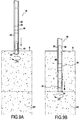
- the figure 1 is a sectional view taken in a vertical plane showing a treatment device 10 according to the invention, intended to treat a portion of soil defined from a depth P below the surface S of the soil. If we refer to the Figure 9A which illustrates a first step of the treatment method according to the invention implemented by means of said device 10, the portion of soil to be treated is designated by the sign ST.
- the device 10 is moved vertically, for vertical drilling.
- This device could also be used for horizontal drilling or inclined drilling.
- the processing device 10 comprises a longitudinal rotating shaft 20 of main axis X fixed to rotation means not shown here but otherwise known, and a hollow elongate member or outer tubular member 30, in particular a tube, here coaxial to the rotating shaft 20 and surrounding the latter.
- the processing device 10 described in the example is used in the implementation of a method of soil mixing.
- Soil mixing is a process of treating a portion of soil by mixing the destructured soil with a fluid, such as a slurry or a reagent, to change its mechanical, physical and / or chemical properties.
- a fluid such as a slurry or a reagent
- the rotary shaft 20 comprises, at its lower end, a drilling tool 24, for example a trilame, intended to drill the ground to ensure the progression of the device 10.
- a drilling tool 24 for example a trilame, intended to drill the ground to ensure the progression of the device 10.
- a longitudinal pipe 22 passes through the rotary shaft for the injection of a fluid of the aforementioned type near the lower end 28 of the shaft 20.
- the longitudinal pipe 22 passes through the tool drilling 24 and opens at an injection port 23 located at the lower end of said tool.
- the outer tubular element 30 also has cutting teeth 39 at its lower end 38.
- the rotating shaft 20 may, when the soil portion to be treated ST is deep, be constituted by a succession of rods screwed to each other.
- the tubular element 30 can take the form of a train of tubes.
- both the rotary shaft 20 and the tubular element 30 are formed by the assembly, including screwing, of several successive sections.
- the shaft 20 is provided with a deployable mixer tool 40 here comprising two similar arms 42 disposed on either side of a diameter of the shaft 20.
- the inner wall of the tubular member 30 acts on the arms 42 to bring them into a retracted position in which they extend along the lower end of the shaft 20. In this position, the entirety of each arm 42 runs along the shaft 20. In this way, the drill bit 24, which projects at least partially beyond the lower end of the tubular member 30, can pierce the ground freely.
- the two arms 42 are pivotally mounted on the lower end 28 of the shaft 20 about axes orthogonal to the longitudinal direction X of the shaft 20. In this way, the arms 42 can extend laterally with respect to the longitudinal direction X of the shaft 20.
- Spring means 44 are arranged between the rotary shaft 20 and each of the two arms 42 so that these arms 42 have a natural tendency to deploy with respect to the axis X of the shaft 20 thanks to the action of the springs 44, when out of the tubular element 30.
- the arms 42 in their deployed position, form an open angle towards the lower end of the shaft, as shown in FIG. Figure 9D .
- the arms 42 make it possible to destructure the ground when the shaft 20 is rotated.
- the rotary shaft 20 has a generally circular section, of constant diameter.
- the tubular element 30 has a generally annular section of constant internal and external diameters.
- the outer diameter of the rotary shaft 20 is smaller than the internal diameter of the tubular element 30.
- An annular passage 60 visible on the figure 1 , is thus preserved between the two elements 20, 30. As will be described in more detail below, this passage 60 allows the recovery of drilling waste, that is, the disintegrated soil mixture and drilling fluid from the drilling operation.
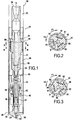
- the device 10 comprises a defusible coupling system 50 between the rotary shaft 20 and the tubular element 30.
- the coupling system 50 is situated upstream of the mixing tool 40.
- the coupling system 50 comprises first elements fixed to or forming an integral part of the tubular element 30 and second elements fixed to or forming an integral part of the rotary shaft 20. By cooperating, these first and second elements block certain relative degrees of freedom between the tubular element 30 and the rotary shaft 20.
- the coupling system 50 comprises a plurality of lugs 54 formed on the inner wall of the tubular element 30, adapted to cooperate with a corresponding number of housings 52 formed on the outer wall of the rotary shaft.
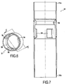
- FIGS. 6 and 7 illustrate a section 31 of the tubular element 30 on which the lugs 54 are formed. This section 31 is threaded at each end 31a, 31b for its attachment to a tube 32, 33, respectively head and foot, of the element tubular 30.
- Each lug 54 is similar, in the example, to an angular sector of an internal collar formed on the inner wall of the tubular element 30.
- the coupling system comprises three lugs 54 distributed on the inner wall of the tubular element, forming between them angles of 120 °.
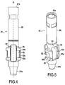
- the housings 52 are formed in projecting parts 53 formed at the periphery of the rotary shaft 20.
- FIGS. 4 and 5 in particular, illustrate a section 21 of the rotary shaft 20 comprising these protruding parts 53.
- This section 21 is threaded at each end 21a, 21b for attachment to a complementary section of the rotary shaft 20.
- the outer radial face of the protruding parts 53 extends along the inner face of the tubular element 30.
- the rotary shaft 20 has longitudinally extending grooves 51 (i.e. in the main direction X).
- Each groove 51 communicates respectively with one of the housings 52 and has a width sufficient to allow a lug 54 to slide inside in the axial direction.
- the depth of the grooves 51 is chosen to ensure a sufficient flow section for the drilling waste.
- the projecting parts 53 constitute a flow restriction for said waste, which can be compensated, at least in part, by said grooves.
- each housing 52 is in the form of a notch, here of complementary profile to that of the lugs 54, made in the outer wall of the projecting portions 53 of the rotary shaft 20.
- F1 be the clockwise direction illustrated in the different figures.
- the lugs 54 each abut against the vertical wall 52c of their housing 52 (defined in a substantially axial plane).
- the rotary shaft 20 thus causes, in its movement, the tubular element 30.
- the soil is broken up by the drilling tool 24 in the center and by the drill bits 39 at the periphery of the device 10.
- a drilling fluid generally water, is conveyed into the soil, proximity of the drilling tool 24, by the longitudinal pipe 22.
- the mixture of soil and drilling fluid rises through the annular passage 60 formed between the tubular element 30 and the rotary shaft 20.
- the mixture passes into the grooves 51 formed at the periphery of the pipe. shaft 20, between the protruding parts 53.
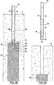
- the coupling system 50 is moved to its second position, as illustrated in FIG. Figure 9C .
- the rotary shaft 20 is rotated in the counterclockwise direction F2, by about 45 °, of so that the lugs 54 are extracted from their respective housing 52 and introduced into the grooves 51.
- the coupling system is then in its second configuration, in which the rotary shaft 20 and the tubular element 30 are no longer coupled in rotation or in translation.
- the rotary shaft 20 can then be moved downstream (X1) until its lower end, and in particular the mixing tool 40, is extracted from the tubular element 30 and enters the portion of soil to be treated ST.
- the shaft 20 is then rotated while injecting a fluid into the soil portion ST through the lower end of the shaft 20, whereby the treated area is circumscribed to said portion of ground.
- the rotary shaft 20 is raised (X2), until the mixing tool 40, in particular, is housed again inside the tubular element 30.
- the rotary shaft 20 is translated upstream along the main axis X, and simultaneously rotated.
- the grooves 51 of the rotary shaft 20 are opposite lugs 54, which lodge there automatically.
- an internal flange 56 is formed upstream of the lugs 54 on the inner wall of the tubular element 30.
- This inner flange 56 has an inner diameter smaller than the diameter of the rotary shaft 20 on its downstream portion, in particular the diameter of the circle in which the projecting parts are inscribed 53.
- the flange 56 forms a continuous annular border, which ensures the locking in translation of the rotary shaft 20 relative to the tubular element 30 regardless of the angular position of the rotary shaft 20.
- the stop formed by the flange 56 ensures the easy removal of the tubular element 30 simultaneously with the rotary shaft 20.
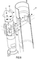
- FIGS. 10A to 10F illustrate the assembly, in progress, of a device 10 according to the invention wherein the rotary shaft 20 and the tubular element 30 are respectively a drill string and a string of tubes.
- a lower rod 201 (or first rod) of the rotary shaft 20 is fixed to a displacement device comprising a rotation head 70 and surrounded by a lower tube 301 (or first tube) of the tubular element 30. note that, for reasons which will be detailed later, a portion of the first rod 201 projects at the upper end of the first tube 301.
- a coupling system 50 of the type described above is formed between the first rod 201 and the first tube 301, and brought into its first configuration.
- the first rod 201 and the first tube 301 are coupled in rotation in the screwing direction of the rods, which will also correspond, for obvious reasons, to the direction of rotation of the device during drilling operations.
- a drilling tool 24 is provided at the lower end of the first rod 201, and a mixing tool 40 is provided between the coupling system 50 and the drill bit 24.
- Two guillotines respectively upstream 81 and downstream 82, are arranged in line with the location provided for drilling, and therefore the portion of soil to be treated.
- a first step illustrated on the figure 10B , the assembly is rotated by the rotation head 70 and translated downstream so as to penetrate into the ground, until the first tube 301 is opposite the downstream guillotine 82 and that the portion the first rod 201 opening out of the tube 301 is opposite the upstream guillotine 81.
- the downstream guillotine 82 is clamped around the first tube 301.
- the first tube 301 and the first rod 201 being coupled in rotation through the coupling system 50, the first rod 201 is immobilized in the usual direction of rotation of the device.
- the first rod 201 is therefore, in the same way, "taken in vice” by the upstream guillotine 81.
- the rotation head 70 is unscrewed.
- the upstream guillotine 81 is again loosened, and the rotation head 70, remote to allow screwing on the second rod 201 and the second tube 301, respectively of a third rod and a third tube (not shown) .
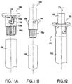
- a processing device 100 according to a second embodiment of the present invention is illustrated on the Figures 11A, 11B and 12 .
- the mixing tool and the drilling tool remain positioned as in the embodiment described above, and their respective structures also remain identical. They are not represented or described again.
- This embodiment differs essentially from the previous one in that the coupling system 150 is situated in the vicinity of the upper end of the device 100.
- the coupling system 150 comprises a plurality of pins (here three) 154, formed this time on the outer wall of the rotary shaft 120, and a corresponding number of housings 152 formed in the wall of the tubular element 130.
- the coupling system 150 As the coupling system 150 is located at the upper end of the device, it is necessary that it can be disassembled in cases where the rotary shaft 120 and the tubular element 130 are respectively a drill string and a gear train. tubes.
- the coupling system 150 thus comprises two parts 158, 159 removably attached respectively to the upper end of the tubular element 130 and to the upper end of the rotary shaft 120.
- a first piece 158 in the form of a sleeve, is adapted to cooperate with the upper end of a tube of the tubular element 130 by its threaded end 158a (see FIG. figure 11A ).
- a second piece 159 substantially cylindrical, is adapted to cooperate with the upper end of a rod of the rotary shaft 20 by its threaded end 159a (see FIG. Figure 11B ).
- the three lugs 154 are adapted to slide in the corresponding slots 152 formed on the first piece 158.
- each slot 152 has a first longitudinally extending section 155a in the X axis direction, a second section 155b extending transversely to said first section 155a, and a return 155c.
- the coupling system 150 is in its first configuration when each lug 154 is positioned in a corresponding return 155c formed on the tubular element 130.
- the rotary shaft 120 and the tubular element 130 are coupled in translation downstream, and in rotation in the clockwise direction F1 (see FIG. figure 12 ).
Landscapes
- Engineering & Computer Science (AREA)
- Life Sciences & Earth Sciences (AREA)
- Structural Engineering (AREA)
- Soil Sciences (AREA)
- Environmental & Geological Engineering (AREA)
- General Life Sciences & Earth Sciences (AREA)
- Civil Engineering (AREA)
- General Engineering & Computer Science (AREA)
- Paleontology (AREA)
- Mining & Mineral Resources (AREA)
- Agronomy & Crop Science (AREA)
- Chemical & Material Sciences (AREA)
- Chemical Kinetics & Catalysis (AREA)
- Consolidation Of Soil By Introduction Of Solidifying Substances Into Soil (AREA)
- Processing Of Solid Wastes (AREA)
Claims (17)
- Vorrichtung (10, 100) zur Bearbeitung eines Bodenabschnitts (ST), umfassend:- eine Drehwelle (20, 120), die sich entlang einer Hauptachse (X) erstreckt und ein oberes Ende (26), das stromaufwärts gerichtet ist, und ein unteres Ende (28), das stromabwärts gerichtet ist, aufweist,- mindestens ein ausfahrbares Mischwerkzeug (40), das an der Drehwelle (20, 120) in der Nähe ihres unteren Endes (28) befestigt ist, und- eine Längsleitung (22) zum Einspritzen eines Fluids in der Nähe des unteren Endes der Drehwelle (20, 120),dadurch gekennzeichnet, dass sie ferner umfasst- ein Bohrwerkzeug (24), das sich am unteren Ende der Welle befindet,- ein äußeres röhrenförmiges Element (30, 130), das sich entlang einer Achse parallel zur Hauptachse (X) der Drehwelle (20, 120) erstreckt, wobei die Drehwelle (20, 120) im Inneren des röhrenförmigen Elements (30, 130) angeordnet ist, und- ein Kupplungssystem (50, 150) zwischen der Drehwelle (20, 120) und dem röhrenförmigen Element (30, 130), wobei das Kupplungssystem (50, 150) in einer ersten Anordnung geeignet ist, das röhrenförmige Element (30, 130) und die Drehwelle (20, 120) in Drehung um die Hauptachse (X) in mindestens eine Drehrichtung zu verbinden, und das röhrenförmige Element (30, 130) und die Drehwelle (20, 120) in Translation entlang der Hauptachse (X), zumindest in stromabwärtige Richtung, zu verbinden, und wobei das Kupplungssystem (50, 150) in einer zweiten Anordnung geeignet ist, die Dreh- und Translationsbewegungen freizugeben.
- Bearbeitungsvorrichtung (10, 100) nach Anspruch 1, bei der das Mischwerkzeug (40) in dem röhrenförmigen Element (30, 130) angeordnet ist, wenn sich das Kupplungssystem (50, 150) in seiner ersten Anordnung befindet.
- Bearbeitungsvorrichtung (10, 100) nach Anspruch 1 oder 2, bei der das Mischwerkzeug (40) geeignet ist, aus dem röhrenförmigen Element (30, 130) herausgezogen und in einen zu bearbeitenden Bodenabschnitt (ST) eingeführt zu werden, wenn sich das Kupplungssystem (50, 150) in seiner zweiten Anordnung befindet.
- Bearbeitungsvorrichtung (10, 100) nach einem der Ansprüche 1 bis 3, bei dem das Kupplungssystem (50, 150) ein System mit Bajonettverschluss ist.
- Bearbeitungsvorrichtung (10, 100) nach Anspruch 4, bei der das Kupplungssystem (50) mindestens einen Haken (54) umfasst, der auf der Innenseite des röhrenförmigen Elements (30) ausgebildet ist, und eine entsprechende Zahl von Kerben (52), die auf der Drehwelle (20) ausgebildet sind, wobei jeder Haken (54) dazu vorgesehen ist, radial und axial an einer Kerbe (52) zum Anschlag zu gelangen.
- Bearbeitungsvorrichtung (10, 100) nach einem der Ansprüche 1 bis 5, bei der das ausfahrbare Mischwerkzeug (40) mindestens einen ausfahrbaren Mischarm (42) umfasst, der am unteren Ende (28) der Drehwelle (20, 120) befestigt ist und sich seitlich in Bezug zur Hauptrichtung (X) der Welle (20, 120) erstreckt, wobei der Arm (42) eine ausgefahrene Position und eine eingezogene Position aufweist, so dass in der ausgefahrenen Position die Reichweite des Mischwerkzeugs (40) größer als der Außendurchmesser des röhrenförmigen Elements (30, 130) ist, um die Bearbeitung des Bodenabschnitts (ST) durch Rotation der Welle (20, 120) zu ermöglichen, und in der eingezogenen Position das Mischwerkzeug (40) geeignet ist, in das röhrenförmige Element (30, 130) eingesetzt zu werden.
- Bearbeitungsvorrichtung (10, 100) nach Anspruch 6, bei der das Mischwerkzeug (40) ferner Federmittel (44) umfasst, die geeignet sind, das Ausfahren des Mischarms (42) aus dem röhrenförmigen Element (30) hervorzurufen und seine Rückkehr in die eingezogene Position beim Einsetzen des unteren Teils (28) der Welle (20, 120) in das röhrenförmige Element (30, 130) zu ermöglichen.
- Bearbeitungsvorrichtung (10, 100) nach einem der Ansprüche 1 bis 7, bei der das Kupplungssystem (50, 150) geeignet ist, das röhrenförmige Element (30, 130) und die Drehwelle (20, 120) in Drehung um die Hauptachse (X) in beide Drehrichtungen zu verbinden.
- Bearbeitungsvorrichtung (10, 100) nach einem der Ansprüche 1 bis 8, bei der das Kupplungssystem (50, 150) ferner dazu geeignet ist, das röhrenförmige Element (30, 130) und die Drehwelle (20, 120) in Translation entlang der Hauptachse (X) in stromaufwärtige Richtung zu verbinden.
- Bearbeitungsvorrichtung (10, 100) nach Anspruch 9, bei der das Kupplungssystem (50) ferner Anschlagmittel (56) umfasst, die dazu vorgesehen sind, mit der Drehwelle (20) zusammenzuwirken, so dass die Drehwelle (20) und das röhrenförmige Element (30) in Translation in stromaufwärtige Richtung unabhängig von der Winkelposition der Drehwelle (20) verbunden werden.
- Bearbeitungsvorrichtung (10, 100) nach Anspruch 10, bei der die Anschlagmittel (56) einen Kragen umfassen, der auf der Innenseite des röhrenförmigen Elements (30) ausgebildet ist, wobei der Innendurchmesser des Kragens (56) kleiner als der maximale Durchmesser der Drehwelle (20) auf dem Abschnitt der Welle (20), der sich stromabwärts zu dem Kragen (56) befindet ist.
- Bearbeitungsvorrichtung (10, 100) nach einem der Ansprüche 1 bis 11, umfassend mindestens zwei Mischvorrichtungen (40), die axial entlang der Hauptachse (X) beabstandet sind.
- Bearbeitungsvorrichtung (10, 100) nach einem der Ansprüche 1 bis 12, bei der das Kupplungssystem (50) in der Nähe des unteren Endes (28) der Drehwelle (20) und des röhrenförmigen Elements (30) vorgesehen ist.
- Verfahren zur Bearbeitung eines Bodenabschnitts, bei dem eine Bearbeitungsvorrichtung (10, 100) nach einem der Ansprüche 1 bis 13 bereitgestellt wird, wobei das Verfahren ferner mindestens die folgenden Schritte umfasst:- Verbinden des röhrenförmigen Elements (30, 130) und der Drehwelle (20, 120), wobei das Kupplungssystem (50, 150) in seine erste Anordnung gebracht wird,- Absenken der Drehwelle (20, 120) in den Boden (S) gemeinsam mit dem röhrenförmigen Element (30, 130) bis zu dem zu bearbeitenden Bodenabschnitt (ST),- Trennen der Drehwelle (20, 120) von dem röhrenförmigen Element (30, 130), wobei das Kupplungssystem (50, 150) in seine zweite Anordnung gebracht wird,- Verschieben der Drehwelle (20, 120) in Bezug zum röhrenförmigen Element (30, 130) bis zur Einführung des Mischwerkzeugs (40) in den zu bearbeitenden Bodenabschnitt (ST),- Ausfahren des Mischwerkzeugs (40), und- Drehen der Welle (20, 120), wobei ein Fluid in den Bodenabschnitt durch die Längsleitung (22) eingespritzt wird, wodurch der Boden des Bodenabschnitts (ST) mit dem Fluid gemischt wird.
- Verfahren zur Bearbeitung eines Bodenabschnitts nach Anspruch 14, bei dem nach der Bearbeitung des Bodenabschnitts (ST) das röhrenförmige Element (30, 130) gemeinsam mit der Drehwelle (20, 120) aus dem Boden herausgezogen wird.
- Verfahren zur Bearbeitung eines Bodenabschnitts nach Anspruch 14 oder 15, bei dem das eingespritzte Fluid ein Reinigungsmittel ist.
- Verfahren zur Bearbeitung eines Bodenabschnitts nach Anspruch 14 oder 15, bei dem das eingespritzte Fluid ein hydraulisches Bindemittel ist.
Priority Applications (1)
| Application Number | Priority Date | Filing Date | Title |
|---|---|---|---|
| PL13815055T PL2931979T3 (pl) | 2012-12-11 | 2013-12-05 | Narzędzie mieszające do obróbki fragmentu gruntu |
Applications Claiming Priority (2)
| Application Number | Priority Date | Filing Date | Title |
|---|---|---|---|
| FR1261906A FR2999200B1 (fr) | 2012-12-11 | 2012-12-11 | Outil melangeur pour le traitement d'une portion de sol |
| PCT/FR2013/052953 WO2014091120A2 (fr) | 2012-12-11 | 2013-12-05 | Outil melangeur pour le traitement d'une portion de sol |
Publications (2)
| Publication Number | Publication Date |
|---|---|
| EP2931979A2 EP2931979A2 (de) | 2015-10-21 |
| EP2931979B1 true EP2931979B1 (de) | 2016-09-21 |
Family
ID=47989105
Family Applications (1)
| Application Number | Title | Priority Date | Filing Date |
|---|---|---|---|
| EP13815055.2A Active EP2931979B1 (de) | 2012-12-11 | 2013-12-05 | Mischwerkzeug für die behandlung eines erdbereiches |
Country Status (10)
| Country | Link |
|---|---|
| US (1) | US9895729B2 (de) |
| EP (1) | EP2931979B1 (de) |
| AU (1) | AU2013357099B2 (de) |
| ES (1) | ES2607847T3 (de) |
| FR (1) | FR2999200B1 (de) |
| HU (1) | HUE032300T2 (de) |
| NZ (1) | NZ709259A (de) |
| PL (1) | PL2931979T3 (de) |
| SG (1) | SG11201504545WA (de) |
| WO (1) | WO2014091120A2 (de) |
Families Citing this family (4)
| Publication number | Priority date | Publication date | Assignee | Title |
|---|---|---|---|---|
| US10406572B2 (en) * | 2014-06-10 | 2019-09-10 | Advanced Environmental Technologies, Llc | Bioelectrochemical devices for enhanced in situ bioremediation |
| FR3047496B1 (fr) | 2016-02-10 | 2019-07-05 | Soletanche Freyssinet | Procede de fabrication d'un tirant d'ancrage et tirant d'ancrage |
| CN106238455A (zh) * | 2016-10-25 | 2016-12-21 | 苏州同和环保工程有限公司 | 用于修复深层污染土的装置及方法 |
| CN115739962B (zh) * | 2022-09-20 | 2023-06-06 | 南京晓庄学院 | 一种多层渗透式土壤修复设备及修复方法 |
Family Cites Families (9)
| Publication number | Priority date | Publication date | Assignee | Title |
|---|---|---|---|---|
| GB102250A (en) * | 1915-11-13 | 1917-06-21 | Lawrence Stewart Campbell | Improvements in or relating to Well-boring Tools. |
| FR2635129A1 (fr) * | 1988-08-03 | 1990-02-09 | Cofor Cie Forage | Perfectionnements aux dispositifs et procedes pour la realisation de pieux en beton dans le sol |
| US5005980A (en) * | 1990-01-05 | 1991-04-09 | Zimmerman Harold M | Sludge/soil mixing machine |
| US5794727A (en) * | 1996-10-25 | 1998-08-18 | Murray; Richard P. | Earth remediation auger |
| JP3837714B2 (ja) * | 1997-07-16 | 2006-10-25 | 三和機材株式会社 | 地盤改良柱体造成機 |
| US6142712A (en) * | 1998-02-03 | 2000-11-07 | White; Richard | Hollow screw-in pile |
| FR2903711B1 (fr) | 2006-07-12 | 2010-12-10 | Cie Du Sol | Outil melangeur pour le traitement d'une portion de sol. |
| ITTO20080503A1 (it) * | 2008-06-27 | 2009-12-28 | Soilmec Spa | Dispositivo di consolidamento di terreni mediante miscelazione meccanica ed iniezione di fluidi di consolidamento |
| IT1403419B1 (it) * | 2010-12-23 | 2013-10-17 | Soilmec Spa | Metodo ed apparato per la perforazione del terreno. |
-
2012
- 2012-12-11 FR FR1261906A patent/FR2999200B1/fr not_active Expired - Fee Related
-
2013
- 2013-12-05 NZ NZ709259A patent/NZ709259A/en not_active IP Right Cessation
- 2013-12-05 SG SG11201504545WA patent/SG11201504545WA/en unknown
- 2013-12-05 PL PL13815055T patent/PL2931979T3/pl unknown
- 2013-12-05 AU AU2013357099A patent/AU2013357099B2/en not_active Ceased
- 2013-12-05 US US14/650,637 patent/US9895729B2/en active Active
- 2013-12-05 WO PCT/FR2013/052953 patent/WO2014091120A2/fr not_active Ceased
- 2013-12-05 HU HUE13815055A patent/HUE032300T2/en unknown
- 2013-12-05 ES ES13815055.2T patent/ES2607847T3/es active Active
- 2013-12-05 EP EP13815055.2A patent/EP2931979B1/de active Active
Also Published As
| Publication number | Publication date |
|---|---|
| EP2931979A2 (de) | 2015-10-21 |
| PL2931979T3 (pl) | 2017-04-28 |
| ES2607847T3 (es) | 2017-04-04 |
| US20150314344A1 (en) | 2015-11-05 |
| FR2999200A1 (fr) | 2014-06-13 |
| FR2999200B1 (fr) | 2015-02-06 |
| NZ709259A (en) | 2017-07-28 |
| SG11201504545WA (en) | 2015-07-30 |
| US9895729B2 (en) | 2018-02-20 |
| AU2013357099B2 (en) | 2017-05-04 |
| AU2013357099A1 (en) | 2015-07-09 |
| HUE032300T2 (en) | 2017-09-28 |
| WO2014091120A2 (fr) | 2014-06-19 |
| WO2014091120A3 (fr) | 2014-08-14 |
| HK1213610A1 (zh) | 2016-07-08 |
Similar Documents
| Publication | Publication Date | Title |
|---|---|---|
| EP3002371B1 (de) | Maschine und verfahren zur erstellung von säulen in einem boden | |
| EP2931979B1 (de) | Mischwerkzeug für die behandlung eines erdbereiches | |
| CA1132900A (fr) | Connecteur a anneau tournant, en particulier pour colonne montante utilisee dans l'exploration ou la production petroliere en mer | |
| FR2713698A1 (fr) | Trépan de forage à pièces rapportées calibrées coupantes libres avec angles de sécurité . | |
| EP2156907B1 (de) | Einrichtung und Verfahren zur Bodensanierung | |
| FR2605657A1 (fr) | Procede pour la realisation d'un pieu dans le sol, machine de forage et dispositif pour la mise en oeuvre de ce procede | |
| EP0505269B1 (de) | Verfahren und Anlage zum Umladen von Materialien von einem verseuchten Raum in einen zweiten Raum, ohne diesen zu verseuchen | |
| FR2814494A1 (fr) | Moteur de trepan de carottage ameliore et procede pour obtenir un echantillon de carotte de materiau | |
| FR2692315A1 (fr) | Système et méthode de forage et d'équipement d'un puits latéral, application à l'exploitation de gisement pétrolier. | |
| FR2538442A1 (fr) | Taillant pour foration rotative assistee par jet | |
| FR2858011A1 (fr) | Dispositif et procede d'echantillonnage en fond de puits | |
| EP2851503B1 (de) | Erdbohrgerät mit einem Ablagegestell mit mehreren Umlaufförderer | |
| EP0457653B1 (de) | Sicherheitshülse und Vorrichtung für Bohrlöcher, insbesondere für ein unterirdischen unter Druck stehenden Flüssigkeitsbehälter | |
| EP1878833B1 (de) | Mischgerät zur Verarbeitung eines Bodenteils | |
| FR2953249A1 (fr) | Composants de garniture de forage et train de composants | |
| EP0382607A1 (de) | Vorrichtung zum Herstellen von Pfählen im Boden mit einem kontinuierlichen hohlen Bohrer | |
| EP2390419B1 (de) | Vorrichtung und Verfahren zum Einbringen von Säulen im Boden | |
| EP0531336B1 (de) | Doppelkernrohr für abgelenkte bohrungen | |
| WO2017025690A1 (fr) | Installation sous-marine de séparation gaz/liquide | |
| EP0287548A1 (de) | Vorrichtung zum Verschliessen eines Kernbohrgerätes in einem Bohrstrang | |
| FR2817790A1 (fr) | Procede et dispositif de formation d'une bonde ainsi que moule de fabrication d'un corps creux equipe d'un tel dispositif | |
| FR3004707A1 (fr) | Systeme de transvasement de liquide d'une recharge a un flacon a filetages internes etages | |
| FR2974141A1 (fr) | Procede et dispositif de forage non destructif | |
| EP3526503B1 (de) | Vorrichtung zum halten eines verbindungsendstücks einer teilweise versenkten flexiblen unterwasserleitung | |
| FR3001250A1 (fr) | Procede de forage comprenant une etape de desolidarisation de l'outil de coupe |
Legal Events
| Date | Code | Title | Description |
|---|---|---|---|
| PUAI | Public reference made under article 153(3) epc to a published international application that has entered the european phase |
Free format text: ORIGINAL CODE: 0009012 |
|
| 17P | Request for examination filed |
Effective date: 20150710 |
|
| AK | Designated contracting states |
Kind code of ref document: A2 Designated state(s): AL AT BE BG CH CY CZ DE DK EE ES FI FR GB GR HR HU IE IS IT LI LT LU LV MC MK MT NL NO PL PT RO RS SE SI SK SM TR |
|
| AX | Request for extension of the european patent |
Extension state: BA ME |
|
| DAX | Request for extension of the european patent (deleted) | ||
| REG | Reference to a national code |
Ref country code: DE Ref legal event code: R079 Ref document number: 602013012010 Country of ref document: DE Free format text: PREVIOUS MAIN CLASS: E02D0005460000 Ipc: B01F0007160000 |
|
| GRAP | Despatch of communication of intention to grant a patent |
Free format text: ORIGINAL CODE: EPIDOSNIGR1 |
|
| RIC1 | Information provided on ipc code assigned before grant |
Ipc: B09C 1/08 20060101ALI20160316BHEP Ipc: E02D 3/00 20060101ALI20160316BHEP Ipc: B01F 7/16 20060101AFI20160316BHEP Ipc: E02D 5/46 20060101ALI20160316BHEP Ipc: B09C 1/02 20060101ALI20160316BHEP |
|
| INTG | Intention to grant announced |
Effective date: 20160414 |
|
| REG | Reference to a national code |
Ref country code: HK Ref legal event code: DE Ref document number: 1213610 Country of ref document: HK |
|
| GRAS | Grant fee paid |
Free format text: ORIGINAL CODE: EPIDOSNIGR3 |
|
| GRAA | (expected) grant |
Free format text: ORIGINAL CODE: 0009210 |
|
| AK | Designated contracting states |
Kind code of ref document: B1 Designated state(s): AL AT BE BG CH CY CZ DE DK EE ES FI FR GB GR HR HU IE IS IT LI LT LU LV MC MK MT NL NO PL PT RO RS SE SI SK SM TR |
|
| REG | Reference to a national code |
Ref country code: GB Ref legal event code: FG4D Free format text: NOT ENGLISH |
|
| REG | Reference to a national code |
Ref country code: CH Ref legal event code: EP |
|
| REG | Reference to a national code |
Ref country code: AT Ref legal event code: REF Ref document number: 830598 Country of ref document: AT Kind code of ref document: T Effective date: 20161015 |
|
| REG | Reference to a national code |
Ref country code: IE Ref legal event code: FG4D Free format text: LANGUAGE OF EP DOCUMENT: FRENCH |
|
| REG | Reference to a national code |
Ref country code: DE Ref legal event code: R096 Ref document number: 602013012010 Country of ref document: DE |
|
| REG | Reference to a national code |
Ref country code: RO Ref legal event code: EPE |
|
| REG | Reference to a national code |
Ref country code: CH Ref legal event code: NV Representative=s name: MICHELI AND CIE SA, CH |
|
| REG | Reference to a national code |
Ref country code: FR Ref legal event code: PLFP Year of fee payment: 4 |
|
| REG | Reference to a national code |
Ref country code: LT Ref legal event code: MG4D Ref country code: NL Ref legal event code: MP Effective date: 20160921 |
|
| PG25 | Lapsed in a contracting state [announced via postgrant information from national office to epo] |
Ref country code: LT Free format text: LAPSE BECAUSE OF FAILURE TO SUBMIT A TRANSLATION OF THE DESCRIPTION OR TO PAY THE FEE WITHIN THE PRESCRIBED TIME-LIMIT Effective date: 20160921 Ref country code: RS Free format text: LAPSE BECAUSE OF FAILURE TO SUBMIT A TRANSLATION OF THE DESCRIPTION OR TO PAY THE FEE WITHIN THE PRESCRIBED TIME-LIMIT Effective date: 20160921 Ref country code: NO Free format text: LAPSE BECAUSE OF FAILURE TO SUBMIT A TRANSLATION OF THE DESCRIPTION OR TO PAY THE FEE WITHIN THE PRESCRIBED TIME-LIMIT Effective date: 20161221 Ref country code: FI Free format text: LAPSE BECAUSE OF FAILURE TO SUBMIT A TRANSLATION OF THE DESCRIPTION OR TO PAY THE FEE WITHIN THE PRESCRIBED TIME-LIMIT Effective date: 20160921 |
|
| REG | Reference to a national code |
Ref country code: AT Ref legal event code: MK05 Ref document number: 830598 Country of ref document: AT Kind code of ref document: T Effective date: 20160921 |
|
| PG25 | Lapsed in a contracting state [announced via postgrant information from national office to epo] |
Ref country code: GR Free format text: LAPSE BECAUSE OF FAILURE TO SUBMIT A TRANSLATION OF THE DESCRIPTION OR TO PAY THE FEE WITHIN THE PRESCRIBED TIME-LIMIT Effective date: 20161222 Ref country code: LV Free format text: LAPSE BECAUSE OF FAILURE TO SUBMIT A TRANSLATION OF THE DESCRIPTION OR TO PAY THE FEE WITHIN THE PRESCRIBED TIME-LIMIT Effective date: 20160921 Ref country code: SE Free format text: LAPSE BECAUSE OF FAILURE TO SUBMIT A TRANSLATION OF THE DESCRIPTION OR TO PAY THE FEE WITHIN THE PRESCRIBED TIME-LIMIT Effective date: 20160921 Ref country code: NL Free format text: LAPSE BECAUSE OF FAILURE TO SUBMIT A TRANSLATION OF THE DESCRIPTION OR TO PAY THE FEE WITHIN THE PRESCRIBED TIME-LIMIT Effective date: 20160921 |
|
| PG25 | Lapsed in a contracting state [announced via postgrant information from national office to epo] |
Ref country code: EE Free format text: LAPSE BECAUSE OF FAILURE TO SUBMIT A TRANSLATION OF THE DESCRIPTION OR TO PAY THE FEE WITHIN THE PRESCRIBED TIME-LIMIT Effective date: 20160921 |
|
| PG25 | Lapsed in a contracting state [announced via postgrant information from national office to epo] |
Ref country code: CZ Free format text: LAPSE BECAUSE OF FAILURE TO SUBMIT A TRANSLATION OF THE DESCRIPTION OR TO PAY THE FEE WITHIN THE PRESCRIBED TIME-LIMIT Effective date: 20160921 Ref country code: BG Free format text: LAPSE BECAUSE OF FAILURE TO SUBMIT A TRANSLATION OF THE DESCRIPTION OR TO PAY THE FEE WITHIN THE PRESCRIBED TIME-LIMIT Effective date: 20161221 Ref country code: AT Free format text: LAPSE BECAUSE OF FAILURE TO SUBMIT A TRANSLATION OF THE DESCRIPTION OR TO PAY THE FEE WITHIN THE PRESCRIBED TIME-LIMIT Effective date: 20160921 Ref country code: IS Free format text: LAPSE BECAUSE OF FAILURE TO SUBMIT A TRANSLATION OF THE DESCRIPTION OR TO PAY THE FEE WITHIN THE PRESCRIBED TIME-LIMIT Effective date: 20170121 Ref country code: SK Free format text: LAPSE BECAUSE OF FAILURE TO SUBMIT A TRANSLATION OF THE DESCRIPTION OR TO PAY THE FEE WITHIN THE PRESCRIBED TIME-LIMIT Effective date: 20160921 Ref country code: PT Free format text: LAPSE BECAUSE OF FAILURE TO SUBMIT A TRANSLATION OF THE DESCRIPTION OR TO PAY THE FEE WITHIN THE PRESCRIBED TIME-LIMIT Effective date: 20170123 Ref country code: SM Free format text: LAPSE BECAUSE OF FAILURE TO SUBMIT A TRANSLATION OF THE DESCRIPTION OR TO PAY THE FEE WITHIN THE PRESCRIBED TIME-LIMIT Effective date: 20160921 |
|
| REG | Reference to a national code |
Ref country code: DE Ref legal event code: R097 Ref document number: 602013012010 Country of ref document: DE |
|
| PG25 | Lapsed in a contracting state [announced via postgrant information from national office to epo] |
Ref country code: IT Free format text: LAPSE BECAUSE OF FAILURE TO SUBMIT A TRANSLATION OF THE DESCRIPTION OR TO PAY THE FEE WITHIN THE PRESCRIBED TIME-LIMIT Effective date: 20160921 |
|
| REG | Reference to a national code |
Ref country code: DE Ref legal event code: R119 Ref document number: 602013012010 Country of ref document: DE |
|
| PLBE | No opposition filed within time limit |
Free format text: ORIGINAL CODE: 0009261 |
|
| STAA | Information on the status of an ep patent application or granted ep patent |
Free format text: STATUS: NO OPPOSITION FILED WITHIN TIME LIMIT |
|
| PG25 | Lapsed in a contracting state [announced via postgrant information from national office to epo] |
Ref country code: DK Free format text: LAPSE BECAUSE OF FAILURE TO SUBMIT A TRANSLATION OF THE DESCRIPTION OR TO PAY THE FEE WITHIN THE PRESCRIBED TIME-LIMIT Effective date: 20160921 |
|
| 26N | No opposition filed |
Effective date: 20170622 |
|
| REG | Reference to a national code |
Ref country code: HU Ref legal event code: AG4A Ref document number: E032300 Country of ref document: HU |
|
| PG25 | Lapsed in a contracting state [announced via postgrant information from national office to epo] |
Ref country code: MC Free format text: LAPSE BECAUSE OF FAILURE TO SUBMIT A TRANSLATION OF THE DESCRIPTION OR TO PAY THE FEE WITHIN THE PRESCRIBED TIME-LIMIT Effective date: 20160921 |
|
| REG | Reference to a national code |
Ref country code: IE Ref legal event code: MM4A |
|
| REG | Reference to a national code |
Ref country code: HK Ref legal event code: GR Ref document number: 1213610 Country of ref document: HK |
|
| PG25 | Lapsed in a contracting state [announced via postgrant information from national office to epo] |
Ref country code: LU Free format text: LAPSE BECAUSE OF NON-PAYMENT OF DUE FEES Effective date: 20161205 |
|
| REG | Reference to a national code |
Ref country code: FR Ref legal event code: PLFP Year of fee payment: 5 |
|
| PG25 | Lapsed in a contracting state [announced via postgrant information from national office to epo] |
Ref country code: IE Free format text: LAPSE BECAUSE OF NON-PAYMENT OF DUE FEES Effective date: 20161205 Ref country code: SI Free format text: LAPSE BECAUSE OF FAILURE TO SUBMIT A TRANSLATION OF THE DESCRIPTION OR TO PAY THE FEE WITHIN THE PRESCRIBED TIME-LIMIT Effective date: 20160921 Ref country code: DE Free format text: LAPSE BECAUSE OF NON-PAYMENT OF DUE FEES Effective date: 20170701 |
|
| PG25 | Lapsed in a contracting state [announced via postgrant information from national office to epo] |
Ref country code: CY Free format text: LAPSE BECAUSE OF FAILURE TO SUBMIT A TRANSLATION OF THE DESCRIPTION OR TO PAY THE FEE WITHIN THE PRESCRIBED TIME-LIMIT Effective date: 20160921 Ref country code: MK Free format text: LAPSE BECAUSE OF FAILURE TO SUBMIT A TRANSLATION OF THE DESCRIPTION OR TO PAY THE FEE WITHIN THE PRESCRIBED TIME-LIMIT Effective date: 20160921 Ref country code: HR Free format text: LAPSE BECAUSE OF FAILURE TO SUBMIT A TRANSLATION OF THE DESCRIPTION OR TO PAY THE FEE WITHIN THE PRESCRIBED TIME-LIMIT Effective date: 20160921 |
|
| PG25 | Lapsed in a contracting state [announced via postgrant information from national office to epo] |
Ref country code: MT Free format text: LAPSE BECAUSE OF FAILURE TO SUBMIT A TRANSLATION OF THE DESCRIPTION OR TO PAY THE FEE WITHIN THE PRESCRIBED TIME-LIMIT Effective date: 20160921 |
|
| PG25 | Lapsed in a contracting state [announced via postgrant information from national office to epo] |
Ref country code: AL Free format text: LAPSE BECAUSE OF FAILURE TO SUBMIT A TRANSLATION OF THE DESCRIPTION OR TO PAY THE FEE WITHIN THE PRESCRIBED TIME-LIMIT Effective date: 20160921 |
|
| PGFP | Annual fee paid to national office [announced via postgrant information from national office to epo] |
Ref country code: TR Payment date: 20211122 Year of fee payment: 9 |
|
| PGFP | Annual fee paid to national office [announced via postgrant information from national office to epo] |
Ref country code: CH Payment date: 20211119 Year of fee payment: 9 Ref country code: BE Payment date: 20211122 Year of fee payment: 9 |
|
| P01 | Opt-out of the competence of the unified patent court (upc) registered |
Effective date: 20230528 |
|
| REG | Reference to a national code |
Ref country code: CH Ref legal event code: PL |
|
| REG | Reference to a national code |
Ref country code: BE Ref legal event code: MM Effective date: 20221231 |
|
| PG25 | Lapsed in a contracting state [announced via postgrant information from national office to epo] |
Ref country code: LI Free format text: LAPSE BECAUSE OF NON-PAYMENT OF DUE FEES Effective date: 20221231 Ref country code: CH Free format text: LAPSE BECAUSE OF NON-PAYMENT OF DUE FEES Effective date: 20221231 |
|
| PG25 | Lapsed in a contracting state [announced via postgrant information from national office to epo] |
Ref country code: BE Free format text: LAPSE BECAUSE OF NON-PAYMENT OF DUE FEES Effective date: 20221231 |
|
| PG25 | Lapsed in a contracting state [announced via postgrant information from national office to epo] |
Ref country code: TR Free format text: LAPSE BECAUSE OF NON-PAYMENT OF DUE FEES Effective date: 20221205 |
|
| PGFP | Annual fee paid to national office [announced via postgrant information from national office to epo] |
Ref country code: GB Payment date: 20251119 Year of fee payment: 13 |
|
| PGFP | Annual fee paid to national office [announced via postgrant information from national office to epo] |
Ref country code: HU Payment date: 20251212 Year of fee payment: 13 Ref country code: FR Payment date: 20251120 Year of fee payment: 13 |
|
| PGFP | Annual fee paid to national office [announced via postgrant information from national office to epo] |
Ref country code: PL Payment date: 20251124 Year of fee payment: 13 |
|
| PGFP | Annual fee paid to national office [announced via postgrant information from national office to epo] |
Ref country code: RO Payment date: 20251203 Year of fee payment: 13 |
|
| PGFP | Annual fee paid to national office [announced via postgrant information from national office to epo] |
Ref country code: ES Payment date: 20260102 Year of fee payment: 13 |