EP2931646B1 - Verbindungselement zwischen einer drehvorrichtung oder ähnlichem werkzeug und einem hydraulischen kranarm - Google Patents
Verbindungselement zwischen einer drehvorrichtung oder ähnlichem werkzeug und einem hydraulischen kranarm Download PDFInfo
- Publication number
- EP2931646B1 EP2931646B1 EP13824535.2A EP13824535A EP2931646B1 EP 2931646 B1 EP2931646 B1 EP 2931646B1 EP 13824535 A EP13824535 A EP 13824535A EP 2931646 B1 EP2931646 B1 EP 2931646B1
- Authority
- EP
- European Patent Office
- Prior art keywords
- link member
- crane arm
- pivot joint
- rotator
- upper pivot
- Prior art date
- Legal status (The legal status is an assumption and is not a legal conclusion. Google has not performed a legal analysis and makes no representation as to the accuracy of the status listed.)
- Active
Links
Images


Classifications
-
- B—PERFORMING OPERATIONS; TRANSPORTING
- B66—HOISTING; LIFTING; HAULING
- B66C—CRANES; LOAD-ENGAGING ELEMENTS OR DEVICES FOR CRANES, CAPSTANS, WINCHES, OR TACKLES
- B66C3/00—Load-engaging elements or devices attached to lifting or lowering gear of cranes or adapted for connection therewith and intended primarily for transmitting lifting forces to loose materials; Grabs
- B66C3/005—Grab supports, e.g. articulations; Oscillation dampers; Orientation
Definitions
- the present invention refers to a link member between a rotational implement or a similar working tool and a hydraulic crane arm, in particular for cranes suitable for mounting onto motor vehicles.
- Such inventions belong to the field of transporting and performing working operations, in particular to cranes, namely to crane arms and gripping devices in view of transmission of lifting forces.
- the aim of the invention is to create a link member of a rotatable gripping device or similar working tool on the hydraulic crane arm, in particular for cranes mounted onto motor vehicles, which should increase reliability in long-term operation of such crane.
- a crane arm with a link member for attaching a working accessory is described in EP 1 889 808 , wherein a rotatable working accessory, in particular a gripping device suitable for gripping and displacing of timbers or similar at least approximately cylindrical objects is attached to such crane arm via the link member.
- Such link member comprises two pivot joints, which are spaced apart from each other in a direction of the vertical axis. Said pivot joints are located on the side of the crane arm as well as on the side of the rotator for the purposes of functioning as a Cardan pivot joint. Both rotation axis, around which pivoting is allowed, are arranged perpendicularly with respect to each other.
- Hydraulic conduits preferably extend along the interior of the crane arm and are directed from the crane arm towards at least approximately horizontally arranged hydraulic connectors on the crane-faced side of rotator which is arranged between said gripping device or working accessory and that side of the link member, which is faced towards said gripping device.
- the pivot joint of the link member, which is facing towards the crane arm comprises two coaxially arranged bearings, which enable rotating, and hydraulic conduits are directed between said bearings towards said hydraulic conduits on said rotator, but outside of that pivot joint of the link member, which is faced towards the rotator.
- Said hydraulic conduits are usually four relatively thick flexible hydraulic hoses, which are due to unhindered movement during operation of the crane loosely placed between said bearings. Due to maneuvering capability of the crane as such and due to preventing the crane from hooking to object in the circumference thereof, said pivot joint as such should be as narrow as possible, but on the contrary, said hydraulic conduits require as much as possible space between said bearing for the purposes of unhindered movement thereof. A compromise between said contradictions leads to quite narrow bearings, and of this reason ball bearings are usually used. Roller bearings and needle bearings are wider and much more expensive, and also lead to undesired enlargement of the width of the pivot joint.
- WO 2011/142704 A further approach is described in WO 2011/142704 , where also a link member is described, via which the hydraulic rotator is connected with the crane arm. Hydraulic conduits are directed along the interior of the crane arm towards the hydraulic connectors on the rotator.
- the member link comprises two pivot joints, namely a bifurcated i.e. double upper pivot joint arranged on the side of the crane arm and a single pivot joint arranged on the side of the rotator, wherein both axis of said pivot joints, around which pivoting is possible, are arranged perpendicularly with respect to each other.
- the link member is furnished with a pin, which is inserted throughout both protrusions of the upper pivot joint and through both bearings, so that the geometric axis of said pin is aligned with the geometric axis of the pivot joint as such, wherein a separate guide for hydraulic circuits is arranged on said pin.
- Said guide is formed of an U-shaped plate, and both arms thereof are furnished with throughout openings, through which said pin is inserted. Hydraulic conduits are directed from the interior of the crane arm over said pin, more exactly between said pin and said guide, and then towards the hydraulic connectors on the rotator. Thanks to said guide, some better guidance of the hydraulic conduits is achieved, which leads to more reliable operation of the crane, but the problem of inappropriate loading and lubricating of the bearings in the pivot joint remains completely unsolved.
- the present invention refers to a link member between a rotational implement or a similar working tool and a hydraulic crane arm, namely a link member, which is on the one hand pivotally connected with said crane arm and on the other hand also pivotally with a hydraulic rotator, which is connectable with each used working accessory or gripping device.
- Such link member comprises two pivot joints, which are located at appropriate distance apart from each other in a direction of vertical axis, namely an upper pivot joint located on the side of the crane arm and a lower pivot joint located on the side of the rotator or each working accessory, so that said pivot joints are conceived as a Cardan pivot link with two rotation axis, which allow pivoting of the link member relative to the crane arm and/or relative to the rotator and which extend perpendicularly with respect to each other.
- the lower pivot joint intended for pivotal interconnection of the link member with the rotator is conceived in form of an eye, which is furnished with a throughout bore, which is directed along said rotational axis of the lower pivot joint and is adapted to receive a bolt
- the upper pivot joint which is located on the side of the crane arm and adapted for establishing a pivotal interconnection therewith, is bifurcated and comprises two protrusions, which are spaced apart from each other and are each per se furnished with a throughout bore adapted to receive a bolt serving for establishing interconnection with the crane arm, and wherein hydraulic conduits, which extend between the crane arm and the rotator, are directed between said extensions of the upper pivot joint of the link member.
- a hollow cylindrical bush is inserted through the bores in the protrusions on the upper pivot joint of the link member on the side of the crane arm, and two bearing bushes are inserted, preferably pressed, therein and are each per se located on corresponding end portion thereof, so that the bolt, which is intended for establishing a pivotal interconnection between the link member and the crane arm in the area of the upper pivot joint of the link member, is inserted through them.
- the protrusions of the upper pivot joint are extended towards the crane arm and are at appropriate distance apart from the bush bridged by a limitation means, while simultaneously the hydraulic conduits are directed from the crane arm towards the link member and then towards to the rotator in such manner that in the area of the upper pivot joint of the link member they extend between the bush and the limitation means towards hydraulic connectors on the rotator.
- Said limitation means is preferably cylindrical and extends parallel to said rotation axis of the upper pivot joint of the link member, and is in particular conceived as a pin extending throughout said protrusions and between them.
- the limitation means is located at a pre-determined distance apart from the bush of the upper pivot joint as well as at a pre-determined distance apart from the vertical axis of the link member, which is defined by angle between a tangent to the limitation means on the side of said vertical axis and the vertical axis itself.
- the distance between the limitation means and the bush is preferably 35 - 55 mm
- the angle between a tangent to the limitation means on the side of the vertical axis and said vertical axis itself is preferably 10 - 30°.
- a roller member can be placed around said limitation means.
- At least one lubricating device adapted for transferring lubricant towards the areas between the bearing bushes and the bolt is foreseen on the bush and/on the bolt, which is mounted on the upper pivot joint (on the side of the crane arm.
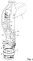
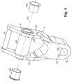
- a crane arm 2 with a member link 1 is partially shown in Fig. 1 , by means of which at a not-shown, at least partially rotatable working accessory, in particular a gripping mechanism adapted for lifting and displacing of timbers or similar approximately cylindrical objects, is attached to said crane arm 2.
- Said link member 1 comprises two pivot joints 11, 12, which are located apart from each other in direction of the vertical axis, namely an upper pivot joint 11, which is located on the side of the crane arm 2, as well as a lower pivot joint 12, which is located on the side of a rotator 3 i.e. a working accessory.
- Said pivot joints 11, 12 on the side of the crane arm 2 and the rotator 3 are conceived to function as a Cardan pivot joint.
- Rotation axis 110, 120 of both pivot joints 11, 12 allowing pivoting, extend perpendicularly with respect to each other.
- the lower pivot joint 12 is conceived as an eye 121 with a throughout bore 122 extending along said rotation axis 120 of the lower pivot joint 12.
- a so-called rotator 3 consisting of a stationary portion 3', which is connectable with said link member 1 and is furnished with hydraulic connectors 31, 32, 33, 34, as well as of a rotatable portion 3", to which said working accessory is connectable.
- Said stationary portion 3' of the rotator 3 is furnished with two eyes 35, 36, which are located at appropriate distance apart from each other and are each per se furnished with a throughout bore 35', 36', so that the lower pivot joint 12 of the link member 1 is inserted between them, wherein the pivotal interconnection between the rotator 3 and the link member 1 is established by means of a bolt 37, which is inserted within said bores 35', 36' on the eyes 35, 36 of the stationary portion 3' of the rotator 3 and at the same time also within a bore 122 on the eye 121 of the lower pivot joint 12 of the link member 1.
- Three hydraulic conduits 41, 42, 43 are presented in the drawings, although in general e.g. four conduits can be placed within the crane arm 2, and extend from said crane arm 2 towards each corresponding hydraulic connectors 31, 32, 33 on the stationary portion 3' of the rotator 3, which are directed horizontally towards the crane arm 2.
- the upper pivot joint 11 on the side of the crane arm 2 is bifurcated i.e. fork-like shaped and comprises two protrusions 111, 112, which are each per se furnished with a throughout bore 111', 112'.
- Said bores 111', 112' of said protrusions 111, 112 extend coaxially along said rotation axis 110 of said upper pivot joint 110.
- a hollow cylindrical bush 113 is inserted through said bores 111', 112' of said protrusions 111, 112, into the interior of which two slide bearing bushes 114', 114" are tightly pressed on both end portions 113', 113" thereof in order to form a slide bearing, through which a bolt 13 is inserted, which serves as a complementary bearing element and which is generally used for the purposes of connecting the link 1 member with the crane arm 2 in the area of the upper pivot joint 11 of said link member 1.
- At least one lubricating device which is not shown in the drawings, can be foreseen on said bush 113 of the upper pivot joint 11, or optionally on said bolt 13, which then serves for the purposes of transferring each lubricant towards both contact surfaces between said bearing bushes 114', 114" and the bolt 13.
- bearing bushes 114', 114" consist of appropriate material with respect to sliding and lubricating properties not only for the purposes of lubricating bushes 114', 114" during rotation relative to the bolt 13 with sufficient velocity to form a so-called lubricating wedge, but also in some different circumstances, when said bushes 114', 114" are just occasionally pivoted around the bolt 13 at relative small angle in the range of approximately ⁇ 15 do 45 degrees relative to the vertical axis.
- said protrusions 111, 112 of the upper pivot joint 11 are extended towards the crane arm 2 and bridged with a limitation means 14 located at appropriate distance apart from said bush 113 i.e. rotation axis 110 of the upper pivot joint 11.
- Said limitation means 14 is preferably cylindrically shaped and extends parallel with respect to said rotation axis 110 of the upper pivot joint 11 of the link member 1.
- the limitation means 14 can be conceived as a pin, which extends throughout said protrusions 111, 112 and between them.
- Said limitation means 14 is used for the purposes of guiding the hydraulic conduits 41, 42, 43 in the sense of appropriate alignment and uniformly bending thereof despite to movement of the rotator 3 towards the crane arm 2 or away from it, and simultaneously for the purposes of preventing said hydraulic conduits 41, 42, 43 from extremely bending and/or disorder.
- the invention provides for a pre-determined arrangement of said limitation means 14, which is defined by means of appropriate distance a apart from the bush 113 of the upper pivot joint 11 as well as by means of appropriate distance apart from the vertical axis of the link member 1, which is defined by means of an angle ⁇ between a tangent t to said limitation means 14 on the side of said vertical axis and the vertical axis as such.
- Said distance a between the limitation means 14 and the bush 113 is 35 - 55 mm, and the angle ⁇ between the tangent t to the limitation means 14 and the vertical axis is 10 - 30°.
- a not shown roller member can be optionally placed around said limitation member 14, although the presence thereof is not required in view of realization of the invention as such.
- Said hydraulic circuits 41, 42, 43 extend from the crane arm 2 towards to the link member 1, wherein in the area of the upper pivot joint 11 they are located between the bush 113 and the limitation means 14, and further extend towards the hydraulic connectors 31, 32, 33 on the rotator 3.
Landscapes
- Engineering & Computer Science (AREA)
- Mechanical Engineering (AREA)
- Jib Cranes (AREA)
- Types And Forms Of Lifts (AREA)
Claims (10)
- Gelenkelement (1) zwischen einem drehbaren Arbeitsmittel oder einem ähnlichen Bearbeitungswerkzeug und einem hydraulischen Kranarm (2), namentlich ein Gelenkelement (1), das einerseits mit dem Kranarm (2) drehbar verbindbar ist und anderseits ebenfalls mit einem hydraulischen Rotator (3) drehbar verbindbar ist, der mit jeder beliebigen verwendeten Arbeits- oder Greifeinrichtung verbindbar ist, wobei das Gelenkelement (1) zwei Drehgelenk (11, 12) umfasst, die in einem geeigneten Abstand voneinander in einer Richtung der Längsachse des Gelenkelements (1) positioniert sind, namentlich ein oberes Drehgelenk (11), das auf der Seite des Kragarms (2) des Gelenkelements (1) positioniert ist, und ein unteres Drehgelenk (12), das auf der Seite des Rotators (3) des Gelenkelements (1) oder jedes beliebigen Arbeitsgeräts positioniert ist, so dass die Drehgelenke (11, 12) als kardanische Drehgelenk mit zwei Drehachse (110, 120) ausgebildet sind, welche die Drehung des Gelenkelements (1) relativ zu dem Kranarm (2) und/oder relativ zum Rotator (3) erlauben und die sich senkrecht zueinander erstrecken, und wobei das untere Drehgelenk (12) für die Drehverbindung des Gelenkelements (1) mit dem Rotator (3) in der Form eines Auges (121) ausgebildet ist, das mit einer Durchgangsbohrung (122) versehen ist, die entlang der Drehachse (120) des unteren Drehgelenks (12) gerichtet ist und dazu eingerichtet ist, einen Bolzen (37) aufzunehmen, während das obere Drehgelenk (11), das auf der Seite des Kranarms (2) des Gelenkelements (1) positioniert und zum Herstellen einer Drehverbindung mit diesem eingerichtet ist, gegabelt ist und zwei Vorsprünge (111, 112) umfasst, die voneinander beabstandet sind und jeder für sich mit einer Durchgangsbohrung (111', 112') versehen ist, die zum Aufnehmen eines zum Herstellen einer Verbindung mit dem Kranarm (2) dienenden Bolzens (13) eingerichtet ist, und wobei Hydraulikleitungen (41, 42, 43), die sich zwischen dem Kranarm (2) und dem Rotator (3) erstrecken, zwischen den Vorsprüngen (111, 112) des oberen Drehgelenks (11) des Gelenkelements (1) eingerichtet sind, dadurch gekennzeichnet, dass eine hohle zylindrische Buchse (113) durch die Bohrungen (111', 112') in den Vorsprüngen (111, 112) an dem oberen Drehgelenk (11) des Gelenkelements (1) auf der Seite des Kranarms (2) des Gelenkelements eingeführt ist, und zwei Lagerbuchsen (114', 114") dort eingeführt sind und jede für sich an einem entsprechenden Endteil (113', 113") davon positioniert ist, so dass der Bolzen (13), der zum Herstellen einer Drehverbindung zwischen dem Gelenkelement (1) und dem Kranarm (2) im Bereich des oberen Drehgelenks (11) des Gelenkelements (1) vorgesehen ist, durch sie eingeführt ist.
- Gelenkelement nach Anspruch 1, dadurch gekennzeichnet, dass die Vorsprünge (111, 112) des oberen Drehgelenks (11) sich zu dem Kranarm (2) hin erstrecken und in einem geeigneten Abstand von der Buchse (113) durch ein Begrenzungsmittel (14) gebrückt sind und dass die Hydraulikleitungen (41, 42, 43) sich vom Kranarm (2) zu dem Gelenkelement (1) und dann zu dem Rotator (3) hin in einer derartigen Weise erstrecken, dass sie sich in dem Bereich des oberen Drehgelenks (11) des Gelenkelements (1) zwischen der Buchse (113) und dem Begrenzungsmittel (14) zu Hydraulikanschlüssen (31, 32, 33) an dem Rotator (3) hin erstrecken.
- Gelenkelement nach Anspruch 2, dadurch gekennzeichnet, dass das Begrenzungsmittel (14) zylindrisch ist und sich parallel zu der Drehachse (110) des oberen Drehgelenks (11) des Gelenkelements (1) erstreckt.
- Gelenkelement nach Anspruch 3, dadurch gekennzeichnet, dass das Begrenzungsmittel (14) als sich durch die Vorsprünge (111, 112) und zwischen diesen erstreckender Stift ausgebildet ist.
- Gelenkelement nach Anspruch 2 oder 3, dadurch gekenntzeichnet, dass das Begrenzungsmittel (14) in einem vorbestimmten Abstand (a) von der Buchse (113) des oberen Drehgelenks (11) ebenso wie in einem vorbestimmten Abstand von der Vertikalachse des Gelenkelements (1) positioniert ist, der durch den Winkel (ϕ) zwischen einer Tangente (t) an das Begrenzungsmittel (14) auf der Seite der Vertikalachse und der Vertikalachse selbst definiert ist.
- Gelenkelement nach Anspruch 5, dadurch gekennzeichnet, dass der Abstand (a) zwischen dem Begrenzungsmittel (14) und der Buchse (113) 35 bis 55 mm beträgt und der Winkel (ϕ) zwischen einer Tangente (t) an das Begrenzungsmittel (14) auf der Seite der Vertikalachse und der Vertikalachse selbst 10 bis 30° beträgt.
- Gelenkelement nach einem der Ansprüche 3 bis 6, dadurch gekennzeichnet, dass ein Rollenelement um das Begrenzungsmittel (14) herum angeordnet ist.
- Gelenkelement nach einem der Ansprüche 1 bis 7, dadurch gekennzeichnet, dass mindestens eine zum Übertragen von Schmiermittel zu den Bereichen zwischen den Lagerbuchsen (114' 114") und dem Bolzen (13) ausgebildete Schmiervorrichtung an der Buchse (113) vorgesehen ist, die an dem oberen Drehgelenk (11) auf der Seite des Kranarms (2) des Gelenkelements (1) angeordnet ist.
- Gelenkelement nach einem der Ansprüche 1 bis 7, dadurch gekennzeichnet, dass mindestens eine zum Übertragen von Schmiermittel zu den Bereichen zwischen den Lagerbuchsen (114', 114") und dem Bolzen (13) ausgebildete Schmiervorrichtung an dem Bolzen (13) vorgesehen ist, die an dem oberen Drehgelenk (11) auf der Seite des Kranarms (2) des Gelenkelements (1) angeordnet ist.
- Gelenkelement nach einem der vorhergehenden Ansprüche, dadurch gekennzeichnet, dass die Lagerbuchsen (114', 114") in die Buchse (113) eingepresst sind.
Applications Claiming Priority (2)
| Application Number | Priority Date | Filing Date | Title |
|---|---|---|---|
| SI201200373A SI24257B (sl) | 2012-12-12 | 2012-12-12 | Pritrdilna enota vrtljivega prijemala ali podobnega delovnega orodja na roki hidravličnega dvigala |
| PCT/SI2013/000077 WO2014092656A1 (en) | 2012-12-12 | 2013-12-05 | Link member between a rotational implement or similar working tool and a hydraulic crane arm |
Publications (2)
| Publication Number | Publication Date |
|---|---|
| EP2931646A1 EP2931646A1 (de) | 2015-10-21 |
| EP2931646B1 true EP2931646B1 (de) | 2016-08-17 |
Family
ID=50023826
Family Applications (1)
| Application Number | Title | Priority Date | Filing Date |
|---|---|---|---|
| EP13824535.2A Active EP2931646B1 (de) | 2012-12-12 | 2013-12-05 | Verbindungselement zwischen einer drehvorrichtung oder ähnlichem werkzeug und einem hydraulischen kranarm |
Country Status (3)
| Country | Link |
|---|---|
| EP (1) | EP2931646B1 (de) |
| SI (1) | SI24257B (de) |
| WO (1) | WO2014092656A1 (de) |
Families Citing this family (1)
| Publication number | Priority date | Publication date | Assignee | Title |
|---|---|---|---|---|
| SI26245A (sl) * | 2021-09-01 | 2023-03-31 | Tajfun Planina proizvodnja strojev, d.o.o | Za tehtanje bremena prirejena pritrdilna enota prijemala na roki dvigala |
Family Cites Families (2)
| Publication number | Priority date | Publication date | Assignee | Title |
|---|---|---|---|---|
| ATE442339T1 (de) | 2006-04-03 | 2009-09-15 | Epsilon Kran Gmbh | Kranarm mit einer befestigungsvorrichtung für arbeitsgeräte |
| SE535793C2 (sv) | 2010-04-13 | 2012-12-18 | Indexator Group Ab | Anordning för styrning av slangar och/eller kablar |
-
2012
- 2012-12-12 SI SI201200373A patent/SI24257B/sl active Search and Examination
-
2013
- 2013-12-05 WO PCT/SI2013/000077 patent/WO2014092656A1/en not_active Ceased
- 2013-12-05 EP EP13824535.2A patent/EP2931646B1/de active Active
Also Published As
| Publication number | Publication date |
|---|---|
| SI24257B (sl) | 2017-07-31 |
| WO2014092656A1 (en) | 2014-06-19 |
| SI24257A (sl) | 2014-06-30 |
| EP2931646A1 (de) | 2015-10-21 |
Similar Documents
| Publication | Publication Date | Title |
|---|---|---|
| EP2558399B1 (de) | Anordnung zur führung von schläuchen und/oder kabeln | |
| RU2723690C1 (ru) | Устройство направления шланга для кранового инструмента | |
| US8496424B2 (en) | Fixing arrangement for a work piece | |
| US9249554B2 (en) | Dipper bail | |
| BRPI0808848A2 (pt) | Dispositivo de trator de cabo elétrico de perfilagem | |
| EP3504145B1 (de) | Rotatoranordnung | |
| EP2931646B1 (de) | Verbindungselement zwischen einer drehvorrichtung oder ähnlichem werkzeug und einem hydraulischen kranarm | |
| EP2949817B1 (de) | Universelle schnellkupplung für löffelbagger | |
| AU2023200670A1 (en) | Mining machine with articulating boom and independent material handling system | |
| EP2396496B1 (de) | Verfahren zur manipulation von stabartigen teilen, zentrierer und gesteinsbohrer | |
| WO2016093386A1 (ko) | 퀵 커플러의 틸팅 구조 | |
| EP3114073B1 (de) | Ausrüstungsbefestigungsvorrichtung für fahrzeuge | |
| BR112019011459B1 (pt) | Manipulador para girar em torno de seu próprio eixo um objeto de manipulação | |
| EP3640514B1 (de) | Hydraulische verbindung und hydraulische auslegerkrananordnung mit einer hydraulischen verbindung | |
| US20170009421A1 (en) | Articulated Operating Arm and Mobile Apparatus with Improved Mounting of Control Member | |
| CN106869218B (zh) | 装载机用可偏转抱叉 | |
| CN220769400U (zh) | 悬吊结构及铁钻工 | |
| CN116547163A (zh) | 建筑工程机器 | |
| CA3032241C (en) | Rotator arrangement | |
| EP3165494A1 (de) | Schlauchschutz für einen gelenkkran und gelenkarmanordnung eines gelenkkrans | |
| CA2539304A1 (en) | Tool for rewinding winch belts | |
| CZ202998A3 (cs) | Stroj s otočně uloženým jeřábem s výložníkem | |
| JP2018087415A (ja) | セントラライザ装置 |
Legal Events
| Date | Code | Title | Description |
|---|---|---|---|
| PUAI | Public reference made under article 153(3) epc to a published international application that has entered the european phase |
Free format text: ORIGINAL CODE: 0009012 |
|
| 17P | Request for examination filed |
Effective date: 20150713 |
|
| AK | Designated contracting states |
Kind code of ref document: A1 Designated state(s): AL AT BE BG CH CY CZ DE DK EE ES FI FR GB GR HR HU IE IS IT LI LT LU LV MC MK MT NL NO PL PT RO RS SE SI SK SM TR |
|
| AX | Request for extension of the european patent |
Extension state: BA ME |
|
| GRAP | Despatch of communication of intention to grant a patent |
Free format text: ORIGINAL CODE: EPIDOSNIGR1 |
|
| DAX | Request for extension of the european patent (deleted) | ||
| INTG | Intention to grant announced |
Effective date: 20160308 |
|
| GRAS | Grant fee paid |
Free format text: ORIGINAL CODE: EPIDOSNIGR3 |
|
| GRAA | (expected) grant |
Free format text: ORIGINAL CODE: 0009210 |
|
| AK | Designated contracting states |
Kind code of ref document: B1 Designated state(s): AL AT BE BG CH CY CZ DE DK EE ES FI FR GB GR HR HU IE IS IT LI LT LU LV MC MK MT NL NO PL PT RO RS SE SI SK SM TR |
|
| REG | Reference to a national code |
Ref country code: GB Ref legal event code: FG4D |
|
| REG | Reference to a national code |
Ref country code: CH Ref legal event code: EP |
|
| REG | Reference to a national code |
Ref country code: IE Ref legal event code: FG4D |
|
| REG | Reference to a national code |
Ref country code: AT Ref legal event code: REF Ref document number: 820856 Country of ref document: AT Kind code of ref document: T Effective date: 20160915 |
|
| REG | Reference to a national code |
Ref country code: DE Ref legal event code: R096 Ref document number: 602013010491 Country of ref document: DE |
|
| REG | Reference to a national code |
Ref country code: FR Ref legal event code: PLFP Year of fee payment: 4 |
|
| REG | Reference to a national code |
Ref country code: NL Ref legal event code: MP Effective date: 20160817 |
|
| REG | Reference to a national code |
Ref country code: LT Ref legal event code: MG4D |
|
| REG | Reference to a national code |
Ref country code: AT Ref legal event code: MK05 Ref document number: 820856 Country of ref document: AT Kind code of ref document: T Effective date: 20160817 |
|
| PG25 | Lapsed in a contracting state [announced via postgrant information from national office to epo] |
Ref country code: NL Free format text: LAPSE BECAUSE OF FAILURE TO SUBMIT A TRANSLATION OF THE DESCRIPTION OR TO PAY THE FEE WITHIN THE PRESCRIBED TIME-LIMIT Effective date: 20160817 Ref country code: FI Free format text: LAPSE BECAUSE OF FAILURE TO SUBMIT A TRANSLATION OF THE DESCRIPTION OR TO PAY THE FEE WITHIN THE PRESCRIBED TIME-LIMIT Effective date: 20160817 Ref country code: LT Free format text: LAPSE BECAUSE OF FAILURE TO SUBMIT A TRANSLATION OF THE DESCRIPTION OR TO PAY THE FEE WITHIN THE PRESCRIBED TIME-LIMIT Effective date: 20160817 Ref country code: HR Free format text: LAPSE BECAUSE OF FAILURE TO SUBMIT A TRANSLATION OF THE DESCRIPTION OR TO PAY THE FEE WITHIN THE PRESCRIBED TIME-LIMIT Effective date: 20160817 Ref country code: RS Free format text: LAPSE BECAUSE OF FAILURE TO SUBMIT A TRANSLATION OF THE DESCRIPTION OR TO PAY THE FEE WITHIN THE PRESCRIBED TIME-LIMIT Effective date: 20160817 Ref country code: NO Free format text: LAPSE BECAUSE OF FAILURE TO SUBMIT A TRANSLATION OF THE DESCRIPTION OR TO PAY THE FEE WITHIN THE PRESCRIBED TIME-LIMIT Effective date: 20161117 |
|
| PG25 | Lapsed in a contracting state [announced via postgrant information from national office to epo] |
Ref country code: LV Free format text: LAPSE BECAUSE OF FAILURE TO SUBMIT A TRANSLATION OF THE DESCRIPTION OR TO PAY THE FEE WITHIN THE PRESCRIBED TIME-LIMIT Effective date: 20160817 Ref country code: PT Free format text: LAPSE BECAUSE OF FAILURE TO SUBMIT A TRANSLATION OF THE DESCRIPTION OR TO PAY THE FEE WITHIN THE PRESCRIBED TIME-LIMIT Effective date: 20161219 Ref country code: PL Free format text: LAPSE BECAUSE OF FAILURE TO SUBMIT A TRANSLATION OF THE DESCRIPTION OR TO PAY THE FEE WITHIN THE PRESCRIBED TIME-LIMIT Effective date: 20160817 Ref country code: AT Free format text: LAPSE BECAUSE OF FAILURE TO SUBMIT A TRANSLATION OF THE DESCRIPTION OR TO PAY THE FEE WITHIN THE PRESCRIBED TIME-LIMIT Effective date: 20160817 Ref country code: SE Free format text: LAPSE BECAUSE OF FAILURE TO SUBMIT A TRANSLATION OF THE DESCRIPTION OR TO PAY THE FEE WITHIN THE PRESCRIBED TIME-LIMIT Effective date: 20160817 Ref country code: GR Free format text: LAPSE BECAUSE OF FAILURE TO SUBMIT A TRANSLATION OF THE DESCRIPTION OR TO PAY THE FEE WITHIN THE PRESCRIBED TIME-LIMIT Effective date: 20161118 Ref country code: ES Free format text: LAPSE BECAUSE OF FAILURE TO SUBMIT A TRANSLATION OF THE DESCRIPTION OR TO PAY THE FEE WITHIN THE PRESCRIBED TIME-LIMIT Effective date: 20160817 |
|
| PGFP | Annual fee paid to national office [announced via postgrant information from national office to epo] |
Ref country code: IT Payment date: 20161231 Year of fee payment: 4 |
|
| PG25 | Lapsed in a contracting state [announced via postgrant information from national office to epo] |
Ref country code: EE Free format text: LAPSE BECAUSE OF FAILURE TO SUBMIT A TRANSLATION OF THE DESCRIPTION OR TO PAY THE FEE WITHIN THE PRESCRIBED TIME-LIMIT Effective date: 20160817 Ref country code: RO Free format text: LAPSE BECAUSE OF FAILURE TO SUBMIT A TRANSLATION OF THE DESCRIPTION OR TO PAY THE FEE WITHIN THE PRESCRIBED TIME-LIMIT Effective date: 20160817 |
|
| REG | Reference to a national code |
Ref country code: DE Ref legal event code: R097 Ref document number: 602013010491 Country of ref document: DE |
|
| PG25 | Lapsed in a contracting state [announced via postgrant information from national office to epo] |
Ref country code: SK Free format text: LAPSE BECAUSE OF FAILURE TO SUBMIT A TRANSLATION OF THE DESCRIPTION OR TO PAY THE FEE WITHIN THE PRESCRIBED TIME-LIMIT Effective date: 20160817 Ref country code: DK Free format text: LAPSE BECAUSE OF FAILURE TO SUBMIT A TRANSLATION OF THE DESCRIPTION OR TO PAY THE FEE WITHIN THE PRESCRIBED TIME-LIMIT Effective date: 20160817 Ref country code: CZ Free format text: LAPSE BECAUSE OF FAILURE TO SUBMIT A TRANSLATION OF THE DESCRIPTION OR TO PAY THE FEE WITHIN THE PRESCRIBED TIME-LIMIT Effective date: 20160817 Ref country code: SM Free format text: LAPSE BECAUSE OF FAILURE TO SUBMIT A TRANSLATION OF THE DESCRIPTION OR TO PAY THE FEE WITHIN THE PRESCRIBED TIME-LIMIT Effective date: 20160817 Ref country code: BE Free format text: LAPSE BECAUSE OF FAILURE TO SUBMIT A TRANSLATION OF THE DESCRIPTION OR TO PAY THE FEE WITHIN THE PRESCRIBED TIME-LIMIT Effective date: 20160817 Ref country code: BG Free format text: LAPSE BECAUSE OF FAILURE TO SUBMIT A TRANSLATION OF THE DESCRIPTION OR TO PAY THE FEE WITHIN THE PRESCRIBED TIME-LIMIT Effective date: 20161117 |
|
| PLBE | No opposition filed within time limit |
Free format text: ORIGINAL CODE: 0009261 |
|
| STAA | Information on the status of an ep patent application or granted ep patent |
Free format text: STATUS: NO OPPOSITION FILED WITHIN TIME LIMIT |
|
| 26N | No opposition filed |
Effective date: 20170518 |
|
| REG | Reference to a national code |
Ref country code: CH Ref legal event code: PL |
|
| PG25 | Lapsed in a contracting state [announced via postgrant information from national office to epo] |
Ref country code: SI Free format text: LAPSE BECAUSE OF FAILURE TO SUBMIT A TRANSLATION OF THE DESCRIPTION OR TO PAY THE FEE WITHIN THE PRESCRIBED TIME-LIMIT Effective date: 20160817 |
|
| PG25 | Lapsed in a contracting state [announced via postgrant information from national office to epo] |
Ref country code: MC Free format text: LAPSE BECAUSE OF FAILURE TO SUBMIT A TRANSLATION OF THE DESCRIPTION OR TO PAY THE FEE WITHIN THE PRESCRIBED TIME-LIMIT Effective date: 20160817 |
|
| REG | Reference to a national code |
Ref country code: IE Ref legal event code: MM4A |
|
| PG25 | Lapsed in a contracting state [announced via postgrant information from national office to epo] |
Ref country code: LI Free format text: LAPSE BECAUSE OF NON-PAYMENT OF DUE FEES Effective date: 20161231 Ref country code: LU Free format text: LAPSE BECAUSE OF NON-PAYMENT OF DUE FEES Effective date: 20161205 Ref country code: CH Free format text: LAPSE BECAUSE OF NON-PAYMENT OF DUE FEES Effective date: 20161231 |
|
| PG25 | Lapsed in a contracting state [announced via postgrant information from national office to epo] |
Ref country code: IE Free format text: LAPSE BECAUSE OF NON-PAYMENT OF DUE FEES Effective date: 20161205 |
|
| REG | Reference to a national code |
Ref country code: FR Ref legal event code: PLFP Year of fee payment: 5 |
|
| PG25 | Lapsed in a contracting state [announced via postgrant information from national office to epo] |
Ref country code: HU Free format text: LAPSE BECAUSE OF FAILURE TO SUBMIT A TRANSLATION OF THE DESCRIPTION OR TO PAY THE FEE WITHIN THE PRESCRIBED TIME-LIMIT; INVALID AB INITIO Effective date: 20131205 |
|
| PG25 | Lapsed in a contracting state [announced via postgrant information from national office to epo] |
Ref country code: IS Free format text: LAPSE BECAUSE OF FAILURE TO SUBMIT A TRANSLATION OF THE DESCRIPTION OR TO PAY THE FEE WITHIN THE PRESCRIBED TIME-LIMIT Effective date: 20160817 Ref country code: CY Free format text: LAPSE BECAUSE OF FAILURE TO SUBMIT A TRANSLATION OF THE DESCRIPTION OR TO PAY THE FEE WITHIN THE PRESCRIBED TIME-LIMIT Effective date: 20160817 Ref country code: MK Free format text: LAPSE BECAUSE OF FAILURE TO SUBMIT A TRANSLATION OF THE DESCRIPTION OR TO PAY THE FEE WITHIN THE PRESCRIBED TIME-LIMIT Effective date: 20160817 |
|
| GBPC | Gb: european patent ceased through non-payment of renewal fee |
Effective date: 20171205 |
|
| PG25 | Lapsed in a contracting state [announced via postgrant information from national office to epo] |
Ref country code: MT Free format text: LAPSE BECAUSE OF NON-PAYMENT OF DUE FEES Effective date: 20161205 |
|
| PG25 | Lapsed in a contracting state [announced via postgrant information from national office to epo] |
Ref country code: IT Free format text: LAPSE BECAUSE OF NON-PAYMENT OF DUE FEES Effective date: 20171205 Ref country code: AL Free format text: LAPSE BECAUSE OF FAILURE TO SUBMIT A TRANSLATION OF THE DESCRIPTION OR TO PAY THE FEE WITHIN THE PRESCRIBED TIME-LIMIT Effective date: 20160817 Ref country code: TR Free format text: LAPSE BECAUSE OF FAILURE TO SUBMIT A TRANSLATION OF THE DESCRIPTION OR TO PAY THE FEE WITHIN THE PRESCRIBED TIME-LIMIT Effective date: 20160817 |
|
| PG25 | Lapsed in a contracting state [announced via postgrant information from national office to epo] |
Ref country code: GB Free format text: LAPSE BECAUSE OF NON-PAYMENT OF DUE FEES Effective date: 20171205 |
|
| PGFP | Annual fee paid to national office [announced via postgrant information from national office to epo] |
Ref country code: DE Payment date: 20251201 Year of fee payment: 13 |
|
| PGFP | Annual fee paid to national office [announced via postgrant information from national office to epo] |
Ref country code: FR Payment date: 20251201 Year of fee payment: 13 |