EP2930491B1 - Test device - Google Patents
Test device Download PDFInfo
- Publication number
- EP2930491B1 EP2930491B1 EP13860648.8A EP13860648A EP2930491B1 EP 2930491 B1 EP2930491 B1 EP 2930491B1 EP 13860648 A EP13860648 A EP 13860648A EP 2930491 B1 EP2930491 B1 EP 2930491B1
- Authority
- EP
- European Patent Office
- Prior art keywords
- test device
- base plate
- magnetizing
- slipping floor
- air bearing
- Prior art date
- Legal status (The legal status is an assumption and is not a legal conclusion. Google has not performed a legal analysis and makes no representation as to the accuracy of the status listed.)
- Active
Links
- 238000012360 testing method Methods 0.000 title claims description 178
- 238000010276 construction Methods 0.000 claims description 34
- 230000007246 mechanism Effects 0.000 description 53
- 238000004088 simulation Methods 0.000 description 34
- 229920005989 resin Polymers 0.000 description 22
- 239000011347 resin Substances 0.000 description 22
- 230000003247 decreasing effect Effects 0.000 description 16
- 230000036316 preload Effects 0.000 description 14
- 239000000203 mixture Substances 0.000 description 11
- 238000006243 chemical reaction Methods 0.000 description 8
- 229920006026 co-polymeric resin Polymers 0.000 description 8
- -1 polytetrafluoroethylene Polymers 0.000 description 8
- 230000005611 electricity Effects 0.000 description 6
- 238000009434 installation Methods 0.000 description 6
- 238000012423 maintenance Methods 0.000 description 5
- 229920002292 Nylon 6 Polymers 0.000 description 4
- 229920002312 polyamide-imide Polymers 0.000 description 4
- 229920001721 polyimide Polymers 0.000 description 4
- 239000009719 polyimide resin Substances 0.000 description 4
- 229920001343 polytetrafluoroethylene Polymers 0.000 description 4
- 239000004810 polytetrafluoroethylene Substances 0.000 description 4
- 241000238631 Hexapoda Species 0.000 description 3
- 238000011056 performance test Methods 0.000 description 3
- 238000012827 research and development Methods 0.000 description 3
- PEVRKKOYEFPFMN-UHFFFAOYSA-N 1,1,2,3,3,3-hexafluoroprop-1-ene;1,1,2,2-tetrafluoroethene Chemical group FC(F)=C(F)F.FC(F)=C(F)C(F)(F)F PEVRKKOYEFPFMN-UHFFFAOYSA-N 0.000 description 2
- 229920001780 ECTFE Polymers 0.000 description 2
- YCKRFDGAMUMZLT-UHFFFAOYSA-N Fluorine atom Chemical compound [F] YCKRFDGAMUMZLT-UHFFFAOYSA-N 0.000 description 2
- 239000002033 PVDF binder Substances 0.000 description 2
- 239000004962 Polyamide-imide Substances 0.000 description 2
- 239000011248 coating agent Substances 0.000 description 2
- 238000000576 coating method Methods 0.000 description 2
- 238000006073 displacement reaction Methods 0.000 description 2
- 230000000694 effects Effects 0.000 description 2
- 229920000840 ethylene tetrafluoroethylene copolymer Polymers 0.000 description 2
- 238000009661 fatigue test Methods 0.000 description 2
- 229910052731 fluorine Inorganic materials 0.000 description 2
- 239000011737 fluorine Substances 0.000 description 2
- 229920002493 poly(chlorotrifluoroethylene) Polymers 0.000 description 2
- 239000005023 polychlorotrifluoroethylene (PCTFE) polymer Substances 0.000 description 2
- 229920002620 polyvinyl fluoride Polymers 0.000 description 2
- 229920002981 polyvinylidene fluoride Polymers 0.000 description 2
- 239000006096 absorbing agent Substances 0.000 description 1
- 150000001875 compounds Chemical class 0.000 description 1
- 239000012467 final product Substances 0.000 description 1
- 238000002955 isolation Methods 0.000 description 1
- 239000000463 material Substances 0.000 description 1
- 239000000047 product Substances 0.000 description 1
- 238000011160 research Methods 0.000 description 1
- 230000035939 shock Effects 0.000 description 1
- 239000000725 suspension Substances 0.000 description 1
- 230000002459 sustained effect Effects 0.000 description 1
- 238000004154 testing of material Methods 0.000 description 1
Images


Classifications
-
- G—PHYSICS
- G09—EDUCATION; CRYPTOGRAPHY; DISPLAY; ADVERTISING; SEALS
- G09B—EDUCATIONAL OR DEMONSTRATION APPLIANCES; APPLIANCES FOR TEACHING, OR COMMUNICATING WITH, THE BLIND, DEAF OR MUTE; MODELS; PLANETARIA; GLOBES; MAPS; DIAGRAMS
- G09B9/00—Simulators for teaching or training purposes
- G09B9/02—Simulators for teaching or training purposes for teaching control of vehicles or other craft
- G09B9/04—Simulators for teaching or training purposes for teaching control of vehicles or other craft for teaching control of land vehicles
-
- G—PHYSICS
- G01—MEASURING; TESTING
- G01M—TESTING STATIC OR DYNAMIC BALANCE OF MACHINES OR STRUCTURES; TESTING OF STRUCTURES OR APPARATUS, NOT OTHERWISE PROVIDED FOR
- G01M17/00—Testing of vehicles
- G01M17/007—Wheeled or endless-tracked vehicles
-
- G—PHYSICS
- G01—MEASURING; TESTING
- G01M—TESTING STATIC OR DYNAMIC BALANCE OF MACHINES OR STRUCTURES; TESTING OF STRUCTURES OR APPARATUS, NOT OTHERWISE PROVIDED FOR
- G01M7/00—Vibration-testing of structures; Shock-testing of structures
- G01M7/02—Vibration-testing by means of a shake table
-
- G—PHYSICS
- G01—MEASURING; TESTING
- G01M—TESTING STATIC OR DYNAMIC BALANCE OF MACHINES OR STRUCTURES; TESTING OF STRUCTURES OR APPARATUS, NOT OTHERWISE PROVIDED FOR
- G01M7/00—Vibration-testing of structures; Shock-testing of structures
- G01M7/02—Vibration-testing by means of a shake table
- G01M7/022—Vibration control arrangements, e.g. for generating random vibrations
-
- G—PHYSICS
- G01—MEASURING; TESTING
- G01M—TESTING STATIC OR DYNAMIC BALANCE OF MACHINES OR STRUCTURES; TESTING OF STRUCTURES OR APPARATUS, NOT OTHERWISE PROVIDED FOR
- G01M7/00—Vibration-testing of structures; Shock-testing of structures
- G01M7/02—Vibration-testing by means of a shake table
- G01M7/027—Specimen mounting arrangements, e.g. table head adapters
-
- G—PHYSICS
- G01—MEASURING; TESTING
- G01M—TESTING STATIC OR DYNAMIC BALANCE OF MACHINES OR STRUCTURES; TESTING OF STRUCTURES OR APPARATUS, NOT OTHERWISE PROVIDED FOR
- G01M7/00—Vibration-testing of structures; Shock-testing of structures
- G01M7/02—Vibration-testing by means of a shake table
- G01M7/06—Multidirectional test stands
-
- G—PHYSICS
- G09—EDUCATION; CRYPTOGRAPHY; DISPLAY; ADVERTISING; SEALS
- G09B—EDUCATIONAL OR DEMONSTRATION APPLIANCES; APPLIANCES FOR TEACHING, OR COMMUNICATING WITH, THE BLIND, DEAF OR MUTE; MODELS; PLANETARIA; GLOBES; MAPS; DIAGRAMS
- G09B9/00—Simulators for teaching or training purposes
- G09B9/02—Simulators for teaching or training purposes for teaching control of vehicles or other craft
- G09B9/08—Simulators for teaching or training purposes for teaching control of vehicles or other craft for teaching control of aircraft, e.g. Link trainer
- G09B9/12—Motion systems for aircraft simulators
- G09B9/14—Motion systems for aircraft simulators controlled by fluid actuated piston or cylinder ram
Definitions
- the invention relates to a test device for executing various tests (hereinafter, referred to as merely “Test” generically); such as loading test by adding the outside power or vibration test by adding the vibration against construction to be tested, for instance, the transportation apparatuses such as the car, the motorcycle, the train, aircraft, and ships, or constructions such as bridge, building, houses, and buildings, or parts etc. thereof (hereinafter, referred to as merely "construction to be tested” generically), or such as simulation test etc. of the driving state according to the driving operation by operator.
- test device there are a vibration test device and a loading test device to research and develop these constructions to be tested.
- driving simulation device (hereinafter, also referred to as merely, "Driving simulator") to simulate the driving state etc. corresponding to the operation of the operator.
- the driving simulation device is explained as an example.
- the driving simulation device for instance, six degree of freedom parallel mechanism, which is called so-called “Stewart platform (it is called “Hexapod”)", is adopted.
- the platform which is connected by the movement connection mechanism that positions six degree of freedom, and in which the parts to be driven such as the vehicle model is provided.
- Patent Document 1 Japanese Patent No. 4736592
- the dome 108 having the vehicle model is provided on the platform 106, which is connected to the base 104 by the movement connecting mechanism 102 that positions six degree of freedom.
- a plurality of the X axial rail 110 disposed on the direction of X axis and a pair of Y axial rail 112, which are movable on the X axial rail 110 on the direction of X axis and are disposed on the direction of Y axis, are provided.
- the base 104 is disposed on this Y axial rail 112 so that it can be moved in the direction of the Y axis.
- Linear guide is composed, so that the dome 108, in which the vehicle model is provided, can be moved in the direction of X-Y.
- Patent Document 2 Japanese Patent No. 3915122
- Fig. 24 the driving simulator 200 is disclosed.
- the dome 208 having the vehicle model is provided.
- a plurality of the air bearing 212 is provided to the lower surface the base 204 to face the slide surface 210.
- the base 204 can be moved in the direction of the X axis.
- the base 204 can be moved in the direction of the Y axis.
- the above-mentioned test device gives the movement of horizontal direction (displacement, velocity, and accelerated velocity) to the construction to be tested.
- Fig. 25 is a perspective view showing the schematic of the vibration testing device, as the conventional test device 300 composed like this.
- this test device 300 is provided with the counter 302, and is provided with a plurality of X axial rail 304 on this counter 302.
- the X axial base 308 and X axial base 314, which are connected with the X axial actuator 312 and which are guided by this X axial rail 304, and which can be moved in the direction of X axis by operating of the X axial actuator 312, are provided.
- a plurality of the Y axial rail 310 is provided on the upper face of the X axial base 308, a plurality of the Y axial rail 310 is provided.
- the Y axial base 314, which is connected with the Y axial actuator 306, and which is guided by this Y axial rail 310, and which can be moved in the direction of Y axis by operating of the Y axial actuator 306, and on which the construction to be tested is sustained, is provided.
- test device in order to intend to the research and development of transportation equipment such as car, motorcycle, train, aircraft, and ships, and in order to intend to the driving ability improvement of person who drives transportation equipment etc., such a test device, is used as a driving simulator, in which the driving state in accordance with the driving operation by the operator and the vibration and accelerated velocity test, etc. is imitated, and such a test device is used as composition part of the driving simulator.
- US 2007/018511 A1 discloses a linear displacement system for a driving simulator.
- the height of the device is risen and the mass of the platform 106 that is the moving part is large.
- the base 104 is composed that it can be moved in the direction of X-Y.
- the base 104 cannot be rotated around the Z shaft (vertical shaft) (Yaw movement). Therefore, the necessary movement when the transportation apparatus is turned is that it is entirely necessary to reproduce in six degree of freedom platform of the moving part.
- the six degree of freedom platform is supported with the air bearing 212, and the vertical direction is not restrained.
- the height of the device is raised, and the mass of the platform 206, which is the moving part, is enlarged.
- the height of the device is raised, and the mass of the platform 206, which is the moving part, is enlarged.
- the object of the invention is to provide a test device, in which driving state according to an actual driving operation of the operator can be simulated, and in which the test of the accelerated velocity etc. according to an actual state of driving can be performed.
- the object of the invention is to provide a test device, in which the weight of the platform that is the moving part is light, and the rigidity is high, and in which a movement steady with a light base can be achieved, and in which the simulation up to a high frequency is possible by small power and little space, and in which it is cheap and compact.
- the object of the invention is to provide a test device, in which the weight of the base plate where the construction to be tested that is the moving part is mounted is light, and the rigidity is high, and in which a movement steady with a light base can be achieved, and in which the test up to a high frequency is possible by small power and little space, and in which it is cheap and compact.
- the invention was invented to achieve the problem and the purpose in the above-mentioned prior art.
- the present invention relates to a test device as defined in independent claim 1.
- the platform in which the parts to be driven such as a vehicle model is provided, is connected to the base plate by the movement connecting mechanism that positions six degree of freedom.
- this base plate can be moved on the slipping floor in the direction of X-Y by the air bearing.
- this base plate is disposed freely and movably to be rotated around Z shaft (Yaw movement).
- the base plate is floated, and the air layer can be generated between the base plate and the slipping floor.
- the platform which is connected on the base plate by the movement connecting mechanism, can be moved on the slipping floor by a minimum frictional force.
- the driving state according to an actual driving operation of the operator can be simulated in small power and little space.
- the magnetizing device which is disposed to the lower surface of the base plate to face the slipping floor, is provided.
- the magnetizing force to the slipping floor of the magnetizing device is a strong state.
- the load capacity in the vertical direction of the platform can be increased with Pre - Load by the air bearing and the magnetizing device.
- the magnetic (magnetizing force) by the magnetizing device and the weight of the platform are combined.
- the weight of the platform is light, and the rigidity is high, and a movement steady with a light base can be achieved, and the simulation and the test up to a high frequency is possible by small power and little space.
- the magnetizing force to the slipping floor of the magnetizing device is a weak state.
- the state is detected by the pressure sensor in non-operating state with a low air pressure of the air bearing, so that the test device is stopped.
- the base plate is moved a constant distance to the stopping because of inertia.
- the frictional force can be decreased and wear-out is decreased, so that lengthening the maintenance cycle of the test device becomes possible.
- test device of the invention is a test device, in which the outside power is applied to the construction to be tested and various tests are performed, the test device comprising:
- the base plate, on which the construction to be tested such as house is mounted can be moved on the slipping floor in the direction of X-Y by the air bearing.
- this base plate is disposed freely and movably to be rotated around Z shaft (Yaw movement).
- the base plate is floated, and the air layer can be generated between the base plate and the slipping floor.
- the construction to be tested on the base plate can be moved on the slipping floor by a minimum frictional force.
- the magnetizing device which is disposed to the lower surface of the base plate to face the slipping floor, is provided.
- the magnetizing force to the slipping floor of the magnetizing device is a strong state.
- the load capacity in the vertical direction of the platform can be increased with Pre - Load by the air bearing and the magnetizing device.
- the magnetic (magnetizing force) by the magnetizing device and the weight of the base plate and the construction to be tested on the base plate are combined.
- the weight of the base plate is light, and the rigidity is high, and a movement steady with a light base can be achieved, and the test up to a high frequency is possible by small power and little space.
- the magnetizing force to the slipping floor of the magnetizing device is a weak state.
- the state is detected by the pressure sensor in non-operating state at a low air pressure of the air bearing, so that the test device is stopped.
- the base plate is moved a constant distance to the stopping because of inertia.
- the frictional force can be decreased and wear-out is decreased, so that lengthening the maintenance cycle of the test device becomes possible.
- test device of the invention is characterized in that, the magnetizing device can be abutted and separated to the slipping floor, and strength of the magnetizing force to the slipping floor can be switched.
- the magnetic force suitable for the test device can be adjusted.
- test device of the invention is characterized in that the magnetizing device is provided with a magnet member, which can be abutted and separated to the slipping floor.
- the magnetic force suitable for the test device can be adjusted.
- the device is stopped in non-operating state at a low air pressure of the air bearing.
- the base plate is moved a constant distance to the stopping because of inertia.
- the magnet member which is the magnetizing device, is moved in the direction separated from the slipping floor.
- the magnetizing force to the slipping floor is a weak state, so that the magnetic force does not act.
- the frictional force can be decreased, and wear-out is decreased.
- test device of the invention is characterized in that the magnet member comprises a permanent magnet.
- the magnet member comprises a permanent magnet
- a cheap, permanent magnet can be used as a magnet member of the magnetizing device, and the cost can be decreased.
- the magnetizing device can be provided with the magnet member, which includes the electromagnet.
- the magnetizing device includes the electromagnet, by changing the size of the current to the electromagnet, the size of the magnetic force (magnetizing force) can be changed, and it becomes easy to control.
- the test device of the invention is characterized in that the magnet member includes a plurality of magnet member, these magnet members are disposed so that the direction of the pole is the position of the right angle mutually.
- magnet members are disposed so that the direction of the pole is the position of the right angle mutually.
- test device of the invention is characterized in that a plurality of air bearing is provided to the lower surface in the base plate through a sphere seat, a plurality of magnetizing device is provided corresponding to the plurality of air bearing.
- a plurality of air bearing is provided to the lower surface in the base plate through the sphered seat.
- the base plate, the entire base plate is uniformly floated by the air pressure of the air bearing, so that the air layer can be generated between the base plate and the slipping floor.
- the platform which is connected on the base plate by the movement connecting mechanism, can be moved on the slipping floor by a minimum frictional force.
- the driving state according to an actual driving operation of the operator can be simulated in small power and little space.
- a plurality of magnetizing device is provided corresponding to the plurality of air bearing.
- test device of the invention is characterized in that a friction decrease treating is applied to a surface faced the slipping floor of the air bearing, or to at least other surface of the upper surface of the slipping floor.
- a sheet comprising, fluorine-based resin; such as polytetrafluoroethylene resin (PTFE), tetrafluoroethylene-par fluoro alkyl vinyl ether copolymer resin (PFA), tetrafluoroethylene-hexafluoropropylene copolymer resin (FEP), polychlorotrifluoroethylene copolymer resin, tetrafluoroethylene-ethylene copolymer resin, chlorotrifluoroethylene-ethylene copolymer resin, polyvinylidene fluoride resin, polyvinyl fluoride resin, or tetrafluoroethylene-hexafluoropropylene-par fluoro alkyl vinyl ether copolymer resin; or polyimide resin (PI); polyamide 6 resin (PA6); polyamide-imide resin (PAI); or peak resin (PEEK) is stuck.
- PI polyimide resin
- PA6 polyamide 6 resin
- PAI polyamide-imide resin
- PEEK peak
- single resin of these resins and mixture thereof is treated by baking-coating.
- friction decrease treating is applied to a surface faced the slipping floor of the air bearing, or to at least other surface of the upper surface of the slipping floor.
- the air bearing can be prevented being damaged when the air bearing comes in contact with the slipping floor, so that the life-span of the device becomes long.
- the air bearing can be prevented being damaged even if it comes in contact somewhat between the air bearing and the slipping floor.
- the platform in which the parts to be driven such as a vehicle model is provided, is connected to the base plate by the movement connecting mechanism that positions six degree of freedom.
- this base plate can be moved on the slipping floor in the direction of X-Y by the air bearing.
- this base plate is disposed freely and movably to be rotated around Z shaft (Yaw movement).
- the base plate is floated, and the air layer can be generated between the base plate and the slipping floor.
- the platform which is connected on the base plate by the movement connecting mechanism, can be moved on the slipping floor by a minimum frictional force.
- the driving state according to an actual driving operation of the operator can be simulated in small power and little space.
- the magnetizing device which is disposed to the lower surface of the base plate to face the slipping floor, is provided.
- the magnetizing force to the slipping floor of the magnetizing device is a strong state.
- the load capacity in the vertical direction of the platform can be increased with Pre - Load by the air bearing and the magnetizing device.
- the magnetic (magnetizing force) by the magnetizing device and the weight of the platform are combined.
- the weight of the platform is light, and the rigidity is high, and a movement steady with a light base can be achieved, and the simulation and the test up to a high frequency is possible by small power and little space.
- the base plate, on which the construction to be tested such as house is mounted can be moved on the slipping floor in the direction of X-Y by the air bearing.
- this base plate is disposed freely and movably to be rotated around Z shaft (Yaw movement).
- the base plate is floated, and the air layer can be generated between the base plate and the slipping floor.
- the construction to be tested on the base plate can be moved on the slipping floor by a minimum frictional force.
- the magnetizing device which is disposed to the lower surface of the base plate to face the slipping floor, is provided.
- the magnetizing force to the slipping floor of the magnetizing device is a strong state.
- the load capacity in the vertical direction of the platform can be increased with Pre - Load by the air bearing and the magnetizing device.
- the magnetic (magnetizing force) by the magnetizing device and the weight of the base plate and the construction to be tested on the base plate are combined.
- the weight of the base plate is light, and the rigidity is high, and a movement steady with a light base can be achieved, and the test up to a high frequency is possible by small power and little space.
- the magnetizing force to the slipping floor of the magnetizing device is a weak state.
- the device is stopped in non-operating state at a low air pressure of the air bearing.
- the base plate is moved a constant distance to the stopping because of inertia.
- the frictional force can be decreased and wear-out is decreased, so that lengthening the maintenance cycle of the test device becomes possible.
- the reference numeral 10 shows the test device that applies the test device of the invention as a whole as the simulation device.
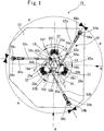
- test device 10 of this Embodiment as shown in Fig. 1 , an embodiment which is applied to the test device according to the driving operation of the operator to simulate driving state.
- the invention is object for research and development of these transportation apparatuses and for improvement of driving abilities of operator who drive the transportation apparatus.
- the invention is object that driving state etc. corresponding to the driving operation of the operator are simulated.
- test device 10 of the invention the screens etc. are provided to the periphery of the test device 10 if required.
- the driving state can visually be simulated according to the driving operation of operator S.
- a slipping floor 12 is provided in the test device 10 of the invention.
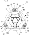
- a base plate 14 of the substantially triangle in the top plan view is disposed, such that it is disposed freely and movably to be rotated around Z shaft (Yaw movement).
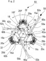
- a movement connecting mechanism 16 is provided on this base plate 14, as shown in Fig. 5 - Fig. 7 .
- the platform 18 comprises the pipe of a so-called truss construction for lightening.
- the movement connecting mechanism 16 in this Embodiment six degree of freedom parallel mechanism, which is called so-called “Stewart platform (it is called “Hexapod”)", is adopted.
- the movement connecting mechanism 16 comprises six links 16a - 16f, which are connected in parallel and are expanding and contracting.
- the platform 18 can be moved in the direction of X-Y-Z.
- the platform 18 can be moved freely so that it can be rotated around X axis (Roll), around Y axis (Pitch), and around Z axis (Yaw movement).
- these links 16a-16f are respectively the structure that the piston cylinder mechanism is operated and expanded and contracted, by operating electricity or oil pressure drive devices 20a-20f (the drawing shows the example of electricity).
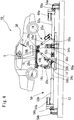
- a vehicle 30 of the car is provided for this Embodiment.
- a plurality of air bearing unit 32 is provided, such that it is faced to the upper surface of the slipping floor 12.
- the air bearing unit 32 is provided with two air bearings 34, which are disposed to the lower surface of the base plate 14 at constant intervals and are disposed, such that they are faced to the upper surface of the slipping floor 12.
- These air bearings 34 are respectively provided to a sphere seat 36 fixed to the lower surface of the base plate 14, such that it is possible to turn freely by a installation portion 38.
- a magnetizing device 40 in which magnetizing force to the slipping floor can be changed, is disposed to the lower surface of base plate 14, such that it is faced to the upper surface of the slipping floor 12.
- This magnetizing device 40 as shown in Fig. 9 - Fig. 11 , a piston cylinder mechanism 42 is provided.
- a base board 46 is fixed to the bottom of a piston 44 of this piston cylinder mechanism 42.
- a magnet member 48 that includes a permanent magnet is disposed to the lower surface of this base board 46.
- the magnet member 48 includes a permanent magnet
- a cheap, permanent magnet can be used as the magnet member 48 of the magnetizing device 40.
- the cost can be decreased, power is not needed, and the energy-saving effect can be expected.
- a spring member 45 is disposed respectively between the base board 46 and a flange 41a of the base edge of four guide members 41 provided to the periphery of the piston 44.
- the air bearing unit 32 composed like this, in the operating state with a high air pressure of the air bearing 34, though not shown in the drawing, according to the air pressure of the air bearing 34, the base plate 14 can be floated, and the air layer is generated between the upper surface of the slipping floor 12.
- the platform 18, which is connected on the base plate 14 by the movement connecting mechanism 16, can be moved on the upper surface of the slipping floor 12 by a minimum frictional force.
- a plurality of the magnetizing device 40 is provided corresponding to a plurality of air bearing 34.
- the air bearing unit 32 is composed that, in the operating state at a high air pressure of the air bearing 34, the magnetizing force to the slipping floor 12 of the magnetizing device 40 is a strong state.
- the magnetizing force of the magnetizing device 40 i.e. attractive force to the slipping floor 12 is a strong state.
- the magnetic force of the magnetizing device 48 is attractive.
- the load capacity in the vertical direction of the platform 18 can be increased with Pre - Load by the air bearing 34 and the magnetizing device 40.
- the magnetic (magnetizing force) by the magnetizing device 40 and the weight of the platform 18 are combined.
- the weight of the platform 18 is light, and the rigidity is high, and a movement steady with a light base can be achieved, and the simulation and the test up to a high frequency is possible by small power and little space.
- a plurality of the magnetizing device 40 is provided corresponding to the plurality of the air bearing 34.
- the number of the air bearing 34 and the magnetizing device 40, and the disposing position in base plate 14 etc. is not especially limited, and is possible to be changed properly.
- the air bearing unit 32 is composed that, since the base board 46 is in a low position, in non-operating state at a low air pressure of the air bearing 34, the magnetizing force i.e. attractive force to the slipping floor 12 of magnetizing device 40 may is a weak state.
- the magnetizing force i.e. attractive force to the slipping floor 12 of the magnetizing device 40 is a weak state.
- the state is detected by the pressure sensor in non-operating state with a low air pressure of the air bearing 34, so that the test device 10 is stopped.
- the base plate 14 is moved a constant distance to the stopping because of inertia.
- the magnetizing force to the slipping floor 12 of the magnetizing device 40 is a weak state.
- the distance between the magnet member 48 disposed to the lower surfaces of the base board 46 and the upper surfaces of the slipping floor 12 becomes large.
- the magnetic force is not acted and the frictional force between the magnet member 48 and the upper surfaces of the slipping floor 12 can be decreased and wear-out is decreased, so that lengthening the maintenance cycle of the test device 10 becomes possible.
- the magnetic force suitable for the test device 10 can be adjusted.
- a friction decrease treating may be applied to a surface faced the slipping floor 12 of the air bearing 34, or to at least other surface of the upper surface of the slipping floor 12.
- Fig. 7 the state, in which the friction decrease treating 11 is applied to the upper surface of the slipping floor 12, is shown.
- a sheet comprising, fluorine-based resin; such as polytetrafluoroethylene resin (PTFE), tetrafluoroethylene-par fluoro alkyl vinyl ether copolymer resin (PFA), tetrafluoroethylene-hexafluoropropylene copolymer resin (FEP), polychlorotrifluoroethylene copolymer resin, tetrafluoroethylene-ethylene copolymer resin, chlorotrifluoroethylene-ethylene copolymer resin, polyvinylidene fluoride resin, polyvinyl fluoride resin, or tetrafluoroethylene-hexafluoropropylene-par fluoro alkyl vinyl ether copolymer resin; or polyimide resin (PI); polyamide 6 resin (PA6); polyamide-imide resin (PAI); or peak resin (PEEK) is stuck.
- PI polyimide resin
- PA6 polyamide 6 resin
- PAI polyamide-imide resin
- PEEK peak
- single resin of these resins and mixture thereof is treated by baking-coating.
- friction decrease treating may be applied to a surface faced the slipping floor 12 of the air bearing 34, or to at least other surface of the upper surface of the slipping floor 12.
- the air bearing 34 can be prevented being damaged when the air bearing 34 comes in contact with the slipping floor 12, so that the life-span of the device becomes long.
- the air bearing 12 can be prevented being damaged even if it comes in contact somewhat between the air bearing 34 and the slipping floor 12.
- the magnet member 48 which is disposed to the lower surface of the base board 46 of the magnetizing device 40, as shown in Fig. 12 , the magnet member 48 may include a plurality of the magnet member 48.
- These magnet members 48 may be disposed so that the direction of the poles are mutually perpendicular to one.
- magnet members 48 are disposed so that the direction of the poles are mutually perpendicular to one another.
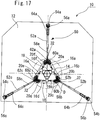
- the base plate 14 is connected with a movement mechanism 50, so that it can be moved on the slipping floor 12 in the direction of X-Y and can be freely and movably rotated around Z shaft (Yaw movement).
- the movement mechanism 50 includes movement drive device 52a, 52b, and 52c, which is composed of three piston cylinder mechanisms that is disposed separately mutually at the angle where the central angle degree ⁇ is 120°.
- the respective tip of piston 58a, 58b, and 58c of these movement drive device 52a, 52b, and 52c is connected pivotally by pivot 62a, 62b, and 62c, to three fixing bracket 60a, 60b, and 60c provided on the base plate 14, such that in the state of Fig. 1 as shown in the dotted line of Fig. 1 , that is, in the top plan view, when the base plate 14 is positioned at the substantially in the center of the upper surface of the slipping floor 12 (when initial position), the central angle degree ⁇ forms 120° mutually according to round circle C.
- extension line at the tip of these piston 58a, 58b, and 58c is provided that in the state of Fig. 1 as shown with the chain line of Fig. 1 , that is, in the top plan view, when the base plate 14 is positioned at the substantially in the center of the upper surface of the slipping floor 12 (when initial position), such that the piston 58a, 58b, and 58c touch the round circle C or they are provided that they become angling near the state to touch the round circle C.
- electricity or oil pressure drive device 64a, 64b, and 64c (the drawing shows the example of electricity) to operate the piston cylinder mechanism is provided.
- the movement mechanism 50 composed like this, according to the operation of operator S, by controlling of the controller (not shown in the drawing), in the operating state at a high air pressure of the air bearing 34, according to the air pressure of the air bearing 34, the base plate 14 is floated, and the air layer can be generated between the base plate and the slipping floor 12.
- the magnetizing force of magnetizing device 40 to the slipping floor 12 is a strong state, and it becomes Pre - Load state.
- the base plate 14 is positioned in the substantially center position of the upper surface of the slipping floor 12, as shown in Fig. 12 - Fig. 16 , the base plate 14 is disposed, such that it is disposed freely and movably to be rotated around Z shaft (Yaw movement) .
- Example is merely shown in the movement of the direction of X-Y and the rotation around the Z axis (Yaw movement).
- the extension line at the tip of the piston 58a, 58b, and 58c is provided that, in the state of Fig. 1 as shown by the chain line of Fig. 2 , that is, in the top plan view, when the base plate 14 is positioned at the substantially in the center of the upper surface of the slipping floor 12 (when initial position), such that the piston 58a, 58b, and 58c touch the round circle C or they are provided that they become angling near the state to touch the round circle C.
- the diameter of the round circle C is a comparatively small.
- the shaft line of the piston cylinder mechanism of the movement drive device 52a, 52b, and 52c, which is the actuator, and the distance at rotation center can be enlarged.
- the movement drive device 52a, 52b, and 52c that is the actuator are disposed.
- the space necessary to provide the movement drive device 52a, 52b, and 52c that is the actuator becomes small and the test device 10 can be miniaturized.
- the piston cylinder mechanism of movement drive device 52a, 52b, and 52c that is the actuator is disposed on the base plate 14.
- the interference generated in the movement drive device 52a, 52b, and 52c can be prevented by the limit switch.
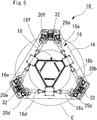
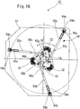
- Fig. 17 is a top view similar to Fig. 1 of the test device of another Embodiment of the invention.
- test device 10 of this Embodiment is basically similar composition of the test device 10 shown in Embodiment 1.
- the respective base edge of the movement drive device 52a, 52b, and 52c is connected pivotally by pivot 56a, 56b, and 56c, to three fixing bracket 54a, 54b, and 54c provided on the base plate 14, such that in the state of Fig. 17 as shown in the dotted line of Fig. 17 , that is, in the top plan view, when the base plate 14 is positioned at the substantially in the center of the upper surface of the slipping floor 12, the central angle degree ⁇ forms 120° mutually according to round large circle D on the upper surface of the slipping floor 12.
- the extension line at the tip of these piston 58a, 58b, and 58c is provided that in the state of Fig. 17 as shown with the chain line D of Fig. 17 , that is, in the top plan view, when the base plate 14 is positioned at the substantially in the center of the upper surface of the slipping floor 12 (when initial position), such that the extension line at the tip of the piston 58a, 58b, and 58c is disposed to the position, in which they are directed to the center O of the base plate 14.
- the tip of the piston 58a, 58b, and 58c is respectively disposed to three corner portions of the base plate 14.
- the angle and the range of the velocity in the direction of Yaw are small, and the torque in the direction of Yaw is small, and the range of the accelerated velocity is small.
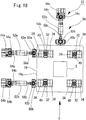
- Fig. 18 is a top view similar to Fig. 2 of the test device of another Embodiment of the invention.
- Fig. 19 is a front view similar to Fig. 3 in the direction of D of Fig. 18 .
- test device 10 of this Embodiment is basically similar composition of the test device 10 shown in Embodiment 1.
- the platforms 18, which comprises the moving part of the substantially triangle in the top plan view, is connected.
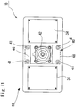
- test device 10 of this Embodiment as shown in Fig. 18 and Fig. 19 , on the base plate 14 that functions as a vibration stand, for instance, construction to be tested E such as houses is provided such that it is fixed by suitable conventional well-known fixing means such as by disposing, and the movement connecting mechanism 16 is not provided.
- the base plate 14 is the base plate 14 of the substantially triangle in the top plan view.
- the base plate 14 is the base plate 14 of the substantially rectangular.
- the movement mechanism 50 includes movement drive device 52a, 52b, and 52c, which is composed of three piston cylinder mechanisms that is disposed separately mutually at the angle where the central angle degree ⁇ is 120°.
- the movement drive device 52a and 52b is disposed so that the piston cylinder mechanism thereof may be expanded and contracted in the direction of the X axis.
- the movement drive device 52a, and 52b are connected with one edge surface 14a in the direction of the X axis, such that they are mutually separated in the direction Y axis.
- the movement drive device 52c is connected with one edge surface 14b in the direction of Y axis.
- a plurality of the air bearing unit 32 is provided to the lower surface of the base plate 14 to face the upper surface of the slipping floor 12, and it is formed to the corner portion of the base plate 14 in three places.
- a plurality of the air bearing unit 32 is provided to the lower surface of the base plate 14 to face the upper surface of the slipping floor 12, and it is formed to the corner portion of the base plate 14 in four places.
- this air bearing unit 32 is provided in three places or more, and the number is not limited.
- the movement mechanism 50 by the movement mechanism 50, it can be applied for a test device, in which the vibration test can be performed in the direction of two shafts (in the direction of X and Y) in a horizontal plane and in the direction of the rotation in the direction of Z axis.
- it can be used for vibration test on the stand for the earthquake, the earthquake resistance test of the construction to be tested E, and lifetime performance test.
- the linear guide of the two-layer is necessary for the conventional horizontal two shaft vibration testing device.
- a big actuator is simultaneously needed, in case of minute amplitude in high frequency, there is a problem that it can not be applied because of fretting wear-out of the linear guide.
- the test device 10 of this Embodiment by using the magnetic force (magnetizing force) together by the air bearing 34 and the magnetizing device 40, the frictional force is small, and the base plate 14 that is the vibrating table lightens.
- Fig. 20 is a front view similar to Fig. 19 of the test device of another Embodiment of the invention.
- test device 10 of this Embodiment is basically similar composition of the test device 10 shown in Embodiment 3.
- Like reference numeral is refer to the same composition member, and the detailed explanation is omitted.
- the construction to be tested E such as houses is provided on the base plate 14.
- a cockpit 70 of the vehicle such as cars is provided as the construction to be tested E.
- test device 10 of this Embodiment can be applied as a simulation device of the vehicle of the three degree of freedom, which can be moved in the direction of X axis and Y axis and which can be rotated around the Z shaft (vertical shaft) (Yaw movement).
- Fig. 21 is a front view similar to Fig. 19 of the test device of another Embodiment of the invention.
- test device 10 of this Embodiment is basically similar composition of the test device 10 shown in Embodiment 3.
- Like reference numeral is refer to the same composition member, and the detailed explanation is omitted.
- a plurality of the air bearing unit 32 is provided to the lower surface of the base plate 14 to face the upper surface of the slipping floor 12, and it is formed to the corner portion of the base plate 14 in four places.
- the magnetizing device 40 is disposed to the lower surface of the base plate 14 to face the upper surface of the slipping floor 12.
- two magnetizing device 40 are disposed to the lower surface of the base plate 14 to face the upper surface of the slipping floor 12 in the state that they are spaced mutually on a central axis G.
- test device 10 of this Embodiment on the corner portion of the right lower side in Fig. 22 , as shown in Fig. 22 , three air bearings 34 are respectively disposed by central angle degree of 120 and along the circular arc.
- the number, the disposing position, and the shape of the air bearing 34, and the disposing position of the magnetizing device 40 may be selected appropriately by combining according to the shape of the base plate 14 and the construction to be tested E, and they are not limited especially.
- a permanent magnet is used as for the magnet member 48 disposed to the lower surface of the base board 46 of the magnetizing device 40.
- the magnetizing device 40 may be provided with the magnet member 48 including the electromagnet.
- the magnetizing device 40 includes the electromagnet, by changing the magnitude of the current to the electromagnet, the magnitude of the magnetic force (magnetizing force) can be changed, and it becomes easy to control.
- the piston cylinder mechanism is used as the movement drive device 52a, 52b, and 52c that are the actuator.
- test device 10 of the invention can be applied to various test devices as follows:
- test device 10 of the invention is composed of the combination of one base plate 14 and the movement mechanism 50.
- one construction to be tested may be disposed on a plurality of base plate 14, so that the test is performed.
- the invention can be applied to a test device for executing various tests; such as loading test by adding the outside power or vibration test by adding the vibration against construction to be tested, for instance, the transportation apparatuses such as the car, the motorcycle, the train, aircraft, and ships, or constructions such as bridge, building, houses, and buildings, or parts etc. thereof, or such as simulation test etc. of the driving state according to the driving operation by operator.
- a test device for executing various tests; such as loading test by adding the outside power or vibration test by adding the vibration against construction to be tested, for instance, the transportation apparatuses such as the car, the motorcycle, the train, aircraft, and ships, or constructions such as bridge, building, houses, and buildings, or parts etc. thereof, or such as simulation test etc. of the driving state according to the driving operation by operator.
Description
- The invention relates to a test device for executing various tests (hereinafter, referred to as merely "Test" generically);
such as loading test by adding the outside power or vibration test by adding the vibration against construction to be tested, for instance,
the transportation apparatuses such as the car, the motorcycle, the train, aircraft, and ships, or
constructions such as bridge, building, houses, and buildings, or
parts etc. thereof (hereinafter, referred to as merely "construction to be tested" generically), or
such as simulation test etc. of the driving state according to the driving operation by operator. - Conventionally, as such a test device, there are a vibration test device and a loading test device to research and develop these constructions to be tested.
- Moreover, in order to improve the research and development of the transportation equipment and driving person's driving ability, there is a driving simulation device (hereinafter, also referred to as merely, "Driving simulator") to simulate the driving state etc. corresponding to the operation of the operator.
- Among such test devices, the driving simulation device is explained as an example.
- The driving simulation device, for instance, six degree of freedom parallel mechanism, which is called so-called "Stewart platform (it is called "Hexapod")", is adopted.
- In this case, six links, which are connected in parallel and are expanding and contracting, are operated cooperatively.
- As a result, the platform, which is connected by the movement connection mechanism that positions six degree of freedom, and in which the parts to be driven such as the vehicle model is provided.
- Moreover, in such six parallel degree of freedom platform, the moving range where is limited.
- As a result, in the direction of advancement and the horizontal direction, and turn of the transportation equipment, the operation of a large amplitude is comparatively reproduced by a low frequency.
- There is a case set up in the mechanism that can be moved on the plane (direction on X, Y, and Yaw).
- As a result, according to the operation person's driving operation, besides keep abreast of movement of X, Y, and Z in three directions, in addition to the gyration around each axis, that is, the tilt movement of six degree of freedom, which is comprising six kinds of movement of back and forth, right and left, vertical direction, roll (Roll), pitch (Pitch), and yaw (Yaw), is reproduced.
- Consequently, driving is simulated according to the driving operation of the operator.
- The operation of small amplitude in a high frequency is comparatively reproduced with the Stewart platform.
- The operation of large amplitude in a low frequency is comparatively reproduced with the plane movement mechanism.
- As for a conventional driving simulation device composed like this, for instance, the driving simulation test device disclosed in Patent Document 1 (Japanese Patent No.
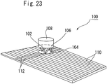
4736592 - In this driving
simulation test device 100, as shown inFig. 23 , thedome 108 having the vehicle model is provided on theplatform 106, which is connected to thebase 104 by themovement connecting mechanism 102 that positions six degree of freedom. - Moreover, a plurality of the X
axial rail 110 disposed on the direction of X axis and a pair of Yaxial rail 112, which are movable on the Xaxial rail 110 on the direction of X axis and are disposed on the direction of Y axis, are provided. - The
base 104 is disposed on this Yaxial rail 112 so that it can be moved in the direction of the Y axis. - As a result, so-called "Linear guide" is composed, so that the
dome 108, in which the vehicle model is provided, can be moved in the direction of X-Y. - Moreover, in Patent Document 2 (Japanese Patent No.
3915122 Fig. 24 , thedriving simulator 200 is disclosed. - In this
driving simulator 200, as shown inFig. 24 , on theplatform 206, which is connected to thebase 204 by themovement connecting mechanism 202 that positions six degree of freedom, thedome 208 having the vehicle model is provided. - Moreover, a plurality of the air bearing 212 is provided to the lower surface the
base 204 to face theslide surface 210. - In addition, in the
driving simulator 200 of Patent Document 2, inFig. 24 , by the X-axis direction moving device that includes the linear guide (not shown in the drawing), thebase 204 can be moved in the direction of the X axis. - Furthermore, by the Y-axis direction moving device (not shown in the drawing), the
base 204 can be moved in the direction of the Y axis. - On the other hand, the above-mentioned test device gives the movement of horizontal direction (displacement, velocity, and accelerated velocity) to the construction to be tested.
- As a result, actual usage condition of these constructions to be tested, and the vibration at the transportation and the earthquake are imitated, so that the performance and durability are tested.
- Therefore, because the movement of the vertical direction (Z axially) is restrained in such a test device, it is general to use a linear guide.
-
Fig. 25 is a perspective view showing the schematic of the vibration testing device, as theconventional test device 300 composed like this. - That is, this
test device 300 is provided with thecounter 302, and is provided with a plurality of Xaxial rail 304 on thiscounter 302. - Moreover, the X
axial base 308 and Xaxial base 314, which are connected with the Xaxial actuator 312 and which are guided by this Xaxial rail 304, and which can be moved in the direction of X axis by operating of the Xaxial actuator 312, are provided. - Moreover, on the upper face of the X
axial base 308, a plurality of the Yaxial rail 310 is provided. - In addition, the Y
axial base 314, which is connected with
the Yaxial actuator 306, and which is guided by this Yaxial rail 310, and which can be moved in the direction of Y axis by operating of the Yaxial actuator 306, and on which the construction to be tested is sustained, is provided. - As like this, in the
conventional test device 300, in order to enable the both movement of X axial direction and Y axial direction, it is necessary to compose a linear guide in two layers as shown inFig. 25 . - Moreover, in order to intend to the research and development of transportation equipment such as car, motorcycle, train, aircraft, and ships, and
in order to intend to the driving ability improvement of person who drives transportation equipment etc.,
such a test device, is used as a driving simulator, in which the driving state in accordance with the driving operation by the operator and the vibration and accelerated velocity test, etc. is imitated, and
such a test device is used as composition part of the driving simulator. -
US 2007/018511 A1 discloses a linear displacement system for a driving simulator. -
- [Patent Document 1]
Japanese Patent No.4736592 - [Patent Document 2]
Japanese Patent No.3915122 - However, in the driving
simulation test device 100 of Patent Document 1, mutually orthogonal Xaxial rail 110 and Yaxial rail 112 are necessary. - As a result, the installation space of the device is large and is necessary.
- Moreover, the height of the device is risen and the mass of the
platform 106 that is the moving part is large. - Therefore, a big driving device is needed and it is enlarged.
- Moreover, in the driving
simulation test device 100 of Patent Document 1, thebase 104 is composed that it can be moved in the direction of X-Y. - However, it is a structure that the
base 104 cannot be rotated around the Z shaft (vertical shaft) (Yaw movement). Therefore, the necessary movement when the transportation apparatus is turned is that it is entirely necessary to reproduce in six degree of freedom platform of the moving part. - As a result, the platform is enlarged further.
- Therefore, in the driving
simulation test device 100 of Patent Document 1, big installation space and driving device are necessary, and the cost is raised. - Moreover, the accelerated velocity of a high frequency at the driving actual state cannot be reproduced.
In addition, driving state according to an actual driving operation of the operator cannot be simulated. - On the other hand, in the driving
simulator 200 of Patent Document 2, the six degree of freedom platform is supported with the air bearing 212, and the vertical direction is not restrained. - Consequently, the
heavy base 204 is necessary to suppress the vibration. - As a result, as well as the driving
simulation test device 100 of Patent Document 1, the installation space of the device is necessary largely. - Moreover, the height of the device is raised, and the mass of the
platform 206, which is the moving part, is enlarged. - As a result, a big driving device is needed and is enlarged.
- Moreover, in the driving
simulator 200 of Patent Document 2, though the mass ofplatform 206 that is the moving part is large, the range of the frequency that can be reproduced is 1-3Hz and suppressing the vibration by a high frequency becomes impossible. - As a result, a heavier base is needed.
- For the test of the accelerated velocity etc. according to an actual state of driving, it is necessary to provide the mechanism of three degree of freedom further on the six degree of freedom platform.
- As a result, it is enlarged and complicate.
- In addition, in the driving
simulator 200 of Patent Document 2, as the surface of theslide surface 210, the slide surface where accuracy is very high is necessary, and the high cost is needed. - Like this, in any case of the driving
simulation test device 100 of Patent Document 1 and the drivingsimulator 200 of Patent Document 2, a big driving device is needed and it is enlarged. - As a result, the high frequency cannot be operated at high speed.
- On the other hand, also in the
conventional test device 300 as shown inFig. 25 , mutually orthogonal Xaxial rail 304 and Yaxial rail 310 are necessary. - As a result, the installation space of the device is necessary largely.
- Moreover, the height of the device is raised, and the mass of the
platform 206, which is the moving part, is enlarged. - Consequently, a big driving device is needed and it is enlarged.
- As a result, the high frequency cannot be operated at high speed.
- Moreover, also in the
conventional test device 300 as shown inFig. 25 , it is composed that it can be moved in the direction of X-Y. - However, it is a structure that the base cannot be rotated around the Z shaft (vertical shaft) (Yaw movement).
- Therefore, in any case of the driving
simulation test device 100 of Patent Document 1, the drivingsimulator 200 of Patent Document 2, and theconventional test device 300 as shown inFig. 25 , it is impossible that the test is performed by applying the vibration in the direction of the rotation against the construction to be tested, and that necessary operation when the transportation apparatus is turned is applied. - In addition, in any case, there is a fault that, when a linear guide is used, the noise is large when it is moved at high-speed, and it is easy to be worn out in minute amplitude.
- Therefore, the object of the invention is to provide a test device,
in which driving state according to an actual driving operation of the operator can be simulated,
and in which the test of the accelerated velocity etc. according to an actual state of driving can be performed. - Moreover, the object of the invention is to provide a test device,
in which the weight of the platform that is the moving part is light, and the rigidity is high,
and in which a movement steady with a light base can be achieved,
and in which the simulation up to a high frequency is possible by small power and little space,
and in which it is cheap and compact. - Moreover, the object of the invention is to provide a test device,
in which the weight of the base plate where the construction to be tested that is the moving part is mounted is light, and the rigidity is high,
and in which a movement steady with a light base can be achieved,
and in which the test up to a high frequency is possible by small power and little space,
and in which it is cheap and compact. - The invention was invented to achieve the problem and the purpose in the above-mentioned prior art.
- The present invention relates to a test device as defined in independent claim 1.
- By composing like this, for instance, the platform, in which the parts to be driven such as a vehicle model is provided, is connected to the base plate by the movement connecting mechanism that positions six degree of freedom.
- Moreover, this base plate can be moved on the slipping floor in the direction of X-Y by the air bearing.
- In addition, this base plate is disposed freely and movably to be rotated around Z shaft (Yaw movement).
- As a result, according to the air pressure of the air bearing, the base plate is floated, and the air layer can be generated between the base plate and the slipping floor.
- Accordingly, the platform, which is connected on the base plate by the movement connecting mechanism, can be moved on the slipping floor by a minimum frictional force.
- Therefore, the driving state according to an actual driving operation of the operator can be simulated in small power and little space.
- As a result, the test of the accelerated velocity etc. according to an actual state of driving can be performed.
- Moreover, the magnetizing device, which is disposed to the lower surface of the base plate to face the slipping floor, is provided.
- In addition, in the operating state at a high air pressure of the air bearing, the magnetizing force to the slipping floor of the magnetizing device is a strong state.
- As a result, the load capacity in the vertical direction of the platform can be increased with Pre - Load by the air bearing and the magnetizing device.
- That is, the magnetic (magnetizing force) by the magnetizing device and the weight of the platform are combined.
- As a result, it enters the state of Pre - Load in the vertical direction of the air bearing, so that it takes charge of the reaction force and the moment in the vertical direction.
- Consequently, a steady simulation and the test become possible.
- As a result, the weight of the platform is light, and the rigidity is high, and a movement steady with a light base can be achieved, and the simulation and the test up to a high frequency is possible by small power and little space.
- In addition, in the non-operating state at a low air pressure of the air bearing, the magnetizing force to the slipping floor of the magnetizing device is a weak state.
- Therefore, the state is detected by the pressure sensor in non-operating state with a low air pressure of the air bearing, so that the test device is stopped.
- However, the base plate is moved a constant distance to the stopping because of inertia.
- In this case, since the magnetizing force to the slipping floor of the magnetizing device is a weak state, magnetic force does not act.
- As a result, the frictional force can be decreased and wear-out is decreased, so that lengthening the maintenance cycle of the test device becomes possible.
- Moreover, the test device of the invention is a test device, in which the outside power is applied to the construction to be tested and various tests are performed,
the test device comprising: - a base plate, which can be moved on a slipping floor in the direction of X-Y by an air bearing, and which is disposed freely and movably to be rotated around Z shaft, and in which the construction to be tested is provided, and
- a magnetizing device, which is disposed to a lower surface of the base plate to face the slipping floor, and in which magnetizing force to the slipping floor can be changed,
- wherein, in the operating state at a high air pressure of the air bearing, the magnetizing force to the slipping floor of the magnetizing device is a strong state, and
- in the non-operating state at a low air pressure of the air bearing, the magnetizing force to the slipping floor of the magnetizing device is a weak state.
- By composing like this, for instance, the base plate, on which the construction to be tested such as house is mounted, can be moved on the slipping floor in the direction of X-Y by the air bearing.
- In addition, this base plate is disposed freely and movably to be rotated around Z shaft (Yaw movement).
- As a result, according to the air pressure of the air bearing, the base plate is floated, and the air layer can be generated between the base plate and the slipping floor.
- Accordingly, the construction to be tested on the base plate can be moved on the slipping floor by a minimum frictional force.
- Therefore, in small power and little space, to the construction to be tested on the base plate, various test, for instance, vibration test on stand for earthquake, longevity performance test, and driving simulation test etc., can be performed.
- As a result, the test according to the actual state is possible.
- Moreover, the magnetizing device, which is disposed to the lower surface of the base plate to face the slipping floor, is provided.
- In addition, in the operating state at a high air pressure of the air bearing, the magnetizing force to the slipping floor of the magnetizing device is a strong state.
- As a result, the load capacity in the vertical direction of the platform can be increased with Pre - Load by the air bearing and the magnetizing device.
- That is, the magnetic (magnetizing force) by the magnetizing device and the weight of the base plate and the construction to be tested on the base plate are combined.
- As a result, it enters the state of Pre - Load in the vertical direction of the air bearing, so that it takes charge of the reaction force and the moment in the vertical direction.
- Consequently, a steady test becomes possible.
- As a result, the weight of the base plate is light, and the rigidity is high, and a movement steady with a light base can be achieved, and the test up to a high frequency is possible by small power and little space.
- In addition, in the non-operating state at a low air pressure of the air bearing, the magnetizing force to the slipping floor of the magnetizing device is a weak state.
- Therefore, the state is detected by the pressure sensor in non-operating state at a low air pressure of the air bearing, so that the test device is stopped.
- However, the base plate is moved a constant distance to the stopping because of inertia.
- In this case, since the magnetizing force to the slipping floor of the magnetizing device is a weak state, magnetic force does not act.
- As a result, the frictional force can be decreased and wear-out is decreased, so that lengthening the maintenance cycle of the test device becomes possible.
- Moreover, the test device of the invention is characterized in that,
the magnetizing device can be abutted and separated to the slipping floor, and
strength of the magnetizing force to the slipping floor can be switched. - By composing like this, by changing the distance to the slipping floor of the magnetizing device, the strength of the magnetizing force to the slipping floor can be switched.
- As a result, the magnetic force suitable for the test device can be adjusted.
- Moreover, the test device of the invention is characterized in that
the magnetizing device is provided with a magnet member, which can be abutted and separated to the slipping floor. - By composing like this, by adjusting the clearance between the magnet member and the slipping floor, the magnetic force suitable for the test device can be adjusted.
- Moreover, the device is stopped in non-operating state at a low air pressure of the air bearing.
- However, the base plate is moved a constant distance to the stopping because of inertia.
- In this case, the magnet member, which is the magnetizing device, is moved in the direction separated from the slipping floor.
- As a result, the magnetizing force to the slipping floor is a weak state, so that the magnetic force does not act.
- Moreover, because the distance between the slipping floor and the magnet member is separated, the frictional force can be decreased, and wear-out is decreased.
- As a result, lengthening the maintenance cycle of the test device becomes possible.
- Moreover, the test device of the invention is characterized in that
the magnet member comprises a permanent magnet. - Thus, if the magnet member comprises a permanent magnet, a cheap, permanent magnet can be used as a magnet member of the magnetizing device, and the cost can be decreased.
- Moreover, because power is not needed to generate the magnetic force, the energy expenditure is decreased.
- Moreover, in the test device of the invention, it is also possible that the magnetizing device can be provided with the magnet member, which includes the electromagnet.
- Thus, if the magnetizing device includes the electromagnet, by changing the size of the current to the electromagnet, the size of the magnetic force (magnetizing force) can be changed, and it becomes easy to control.
- Moreover, the test device of the invention is characterized in that
the magnet member includes a plurality of magnet member,
these magnet members are disposed so that the direction of the pole is the position of the right angle mutually. - Like this, magnet members are disposed so that the direction of the pole is the position of the right angle mutually.
- As a result, it is possible to keep the resist by the eddy current in the direction of each movement (direction of X-Y and Yaw rotation) in the same level.
- Consequently, an accurate simulation and the test can be performed.
- Moreover, the test device of the invention is characterized in that
a plurality of air bearing is provided to the lower surface in the base plate through a sphere seat,
a plurality of magnetizing device is provided corresponding to the plurality of air bearing. - Like this, a plurality of air bearing is provided to the lower surface in the base plate through the sphered seat.
- As a result, the base plate, the entire base plate is uniformly floated by the air pressure of the air bearing, so that the air layer can be generated between the base plate and the slipping floor.
- Consequently, the platform, which is connected on the base plate by the movement connecting mechanism, can be moved on the slipping floor by a minimum frictional force.
- Therefore, the driving state according to an actual driving operation of the operator can be simulated in small power and little space.
- As a result, the test of the accelerated velocity etc. according to an actual state of driving can be performed.
- Moreover, a plurality of magnetizing device is provided corresponding to the plurality of air bearing.
- As a result, the state of Pre - Load in the vertical direction of the air bearing, in which the magnetic force (magnetizing force) by the magnetizing device and the weight of the platform are combined, becomes uniform in the entire base plate.
- Therefore, it takes charge of the reaction force and the moment in the vertical direction.
- Consequently, a steady simulation and the test become possible.
- Moreover, the test device of the invention is characterized in that
a friction decrease treating is applied to a surface faced the slipping floor of the air bearing, or
to at least other surface of the upper surface of the slipping floor. - Thus, for example, a sheet comprising, fluorine-based resin; such as
polytetrafluoroethylene resin (PTFE),
tetrafluoroethylene-par fluoro alkyl vinyl ether copolymer resin (PFA),
tetrafluoroethylene-hexafluoropropylene copolymer resin (FEP),
polychlorotrifluoroethylene copolymer resin,
tetrafluoroethylene-ethylene copolymer resin,
chlorotrifluoroethylene-ethylene copolymer resin,
polyvinylidene fluoride resin,
polyvinyl fluoride resin, or
tetrafluoroethylene-hexafluoropropylene-par fluoro alkyl vinyl ether copolymer resin; or
polyimide resin (PI);
polyamide 6 resin (PA6);
polyamide-imide resin (PAI); or
peak resin (PEEK)
is stuck. - Moreover, single resin of these resins and mixture thereof is treated by baking-coating.
- As a result, friction decrease treating is applied to a surface faced the slipping floor of the air bearing, or to at least other surface of the upper surface of the slipping floor.
- As a result, in case of the emergency stopping etc. or in case that a load which is larger than assumption is applied while operating,
the air bearing can be prevented being damaged when the air bearing comes in contact with the slipping floor, so that the life-span of the device becomes long. - Moreover, because such a friction decrease treating is applied, the air bearing can be prevented being damaged even if it comes in contact somewhat between the air bearing and the slipping floor.
- As a result, because accuracy on the surface of the slipping floor can be somewhat lowered, the cost can be decreased.
- According to the invention, for instance, the platform, in which the parts to be driven such as a vehicle model is provided, is connected to the base plate by the movement connecting mechanism that positions six degree of freedom.
- Moreover, this base plate can be moved on the slipping floor in the direction of X-Y by the air bearing.
- In addition, this base plate is disposed freely and movably to be rotated around Z shaft (Yaw movement).
- As a result, according to the air pressure of the air bearing, the base plate is floated, and the air layer can be generated between the base plate and the slipping floor.
- Accordingly, the platform, which is connected on the base plate by the movement connecting mechanism, can be moved on the slipping floor by a minimum frictional force.
- Therefore, the driving state according to an actual driving operation of the operator can be simulated in small power and little space.
- As a result, the test of the accelerated velocity etc. according to an actual state of driving can be performed.
- Moreover, the magnetizing device, which is disposed to the lower surface of the base plate to face the slipping floor, is provided.
- In addition, in the operating state at a high air pressure of the air bearing, the magnetizing force to the slipping floor of the magnetizing device is a strong state.
- As a result, the load capacity in the vertical direction of the platform can be increased with Pre - Load by the air bearing and the magnetizing device.
- That is, the magnetic (magnetizing force) by the magnetizing device and the weight of the platform are combined.
- As a result, it enters the state of Pre - Load in the vertical direction of the air bearing, so that it takes charge of the reaction force and the moment in the vertical direction.
- Consequently, a steady simulation and the test become possible.
- As a result, the weight of the platform is light, and the rigidity is high, and a movement steady with a light base can be achieved, and the simulation and the test up to a high frequency is possible by small power and little space.
- By composing like this, for instance, the base plate, on which the construction to be tested such as house is mounted, can be moved on the slipping floor in the direction of X-Y by the air bearing.
- In addition, this base plate is disposed freely and movably to be rotated around Z shaft (Yaw movement).
- As a result, according to the air pressure of the air bearing, the base plate is floated, and the air layer can be generated between the base plate and the slipping floor.
- Accordingly, the construction to be tested on the base plate can be moved on the slipping floor by a minimum frictional force.
- Therefore, in small power and little space, to the construction to be tested on the base plate, various test, for instance, vibration test on stand for earthquake, longevity performance test, and driving simulation test etc., can be performed.
- As a result, the test according to the actual state is possible.
- Moreover, the magnetizing device, which is disposed to the lower surface of the base plate to face the slipping floor, is provided.
- In addition, in the operating state at a high air pressure of the air bearing, the magnetizing force to the slipping floor of the magnetizing device is a strong state.
- As a result, the load capacity in the vertical direction of the platform can be increased with Pre - Load by the air bearing and the magnetizing device.
- That is, the magnetic (magnetizing force) by the magnetizing device and the weight of the base plate and the construction to be tested on the base plate are combined.
- As a result, it enters the state of Pre - Load in the vertical direction of the air bearing, so that it takes charge of the reaction force and the moment in the vertical direction. Consequently, a steady test becomes possible.
- As a result, the weight of the base plate is light, and the rigidity is high, and a movement steady with a light base can be achieved, and the test up to a high frequency is possible by small power and little space.
- In addition, in the non-operating state at a low air pressure of the air bearing, the magnetizing force to the slipping floor of the magnetizing device is a weak state.
- Therefore, the device is stopped in non-operating state at a low air pressure of the air bearing.
- However, the base plate is moved a constant distance to the stopping because of inertia.
- In this case, since the magnetizing force to the slipping floor of the magnetizing device is a weak state, magnetic force does not act.
- As a result, the frictional force can be decreased and wear-out is decreased, so that lengthening the maintenance cycle of the test device becomes possible.
-
- [
Fig. 1 ]
Fig. 1 is a top view of the test device applied the test device of the invention as a simulation device. - [
Fig. 2 ]
Fig. 2 is a partial enlarged view ofFig. 1 . - [
Fig. 3 ]
Fig. 3 is a front view seen from the direction of A ofFig. 1 . - [
Fig. 4 ]
Fig. 4 is a drawing that the side view seen from the direction of B ofFig. 1 is rotated right by 90 degrees. - [
Fig. 5 ]
Fig. 5 is a top view of the base plate portion ofFig. 1 . - [
Fig. 6 ]
Fig. 6 is a top view that omits a part of the movement connecting mechanism of the base plate portion inFig. 5 . - [
Fig. 7 ]
Fig. 7 is a drawing that the back view ofFig. 6 is rotated right by 180 degrees. - [
Fig. 8 ]
Fig. 8 is a drawing that the side view in the direction of C ofFig. 6 is rotated right by 90 degrees. - [
Fig. 9 ]
Fig. 9 is an enlarged view of the operating state at a high air pressure of the air bearing, in the air bearing and the portion of the magnetizing device ofFig. 7 . - [
Fig. 10 ]
Fig. 10 is an enlarged view of non-operating state at a low air pressure of the air bearing, in the air bearing and the portion of the magnetizing device ofFig. 7 . - [
Fig. 11 ]
Fig. 11 is a top view of the air bearing and the portion of the magnetizing device ofFig. 7 . - [
Fig. 12 ]
Fig. 12 is a top view explaining the state that the base plate is rotated and moved in a direction of X-Y and around Z shaft on the slipping floor. - [
Fig. 13 ]
Fig. 13 is a top view explaining the state that the base plate is rotated and moved in a direction of X-Y and around Z shaft on the slipping floor. - [
Fig. 14 ]
Fig. 14 is a top view explaining the state that the base plate is rotated and moved in a direction of X-Y and around Z shaft on the slipping floor. - [
Fig. 15 ]
Fig. 15 is a top view explaining the state that the base plate is rotated and moved in a direction of X-Y and around Z shaft on the slipping floor. - [
Fig. 16 ]
Fig. 16 is a top view explaining the state that the base plate is rotated and moved in a direction of X-Y and around Z shaft on the slipping floor. - [
Fig. 17 ]
Fig. 17 is a top view similar toFig. 1 of the test device of another Embodiment of the invention. - [
Fig. 18 ]
Fig. 18 is a top view similar toFig. 2 of the test device of another Embodiment of the invention. - [
Fig. 19 ]
Fig. 19 is a front view similar toFig. 3 in the direction of D ofFig. 18 . - [
Fig. 20 ]
Fig. 20 is a front view similar toFig. 19 of the test device of another Embodiment of the invention. - [
Fig. 21 ]
Fig. 21 is a front view similar toFig. 19 of the test device of another Embodiment of the invention. - [
Fig. 22 ]
Fig. 22 is a schematic view in the F-F line ofFig. 21 . - [
Fig. 23 ]
Fig. 23 is a perspective view of the conventional drivingsimulation test device 100. - [
Fig. 24 ]
Fig. 24 is a partial enlarged side view of theconventional driving simulator 200. - [
Fig. 25 ]
Fig. 25 is a perspective view that shows the schematic of the vibration testing device asconventional test device 300. - Hereafter, the embodiment of the invention (Embodiment) is described in the detail or more on the basis of the drawing.
-
-
Fig. 1 is a top view of the test device applied the test device of the invention as a simulation device. -
Fig. 2 is a partial enlarged view ofFig. 1 . -
Fig. 3 is a front view seen from the direction of A ofFig. 1 . -
Fig. 4 is a drawing that the side view seen from the direction of B ofFig. 1 is rotated right by 90 degrees. -
Fig. 5 is a top view of the base plate portion ofFig. 1 . -
Fig. 6 is a top view that omits a part of the movement connecting mechanism of the base plate portion inFig. 5 . -
Fig. 7 is a drawing that the back view ofFig. 6 is rotated right by 180 degrees. -
Fig. 8 is a drawing that the side view in the direction of C ofFig. 6 is rotated right by 90 degrees. -
Fig. 9 is an enlarged view of the operating state at a high air pressure of the air bearing, in the air bearing and the portion of the magnetizing device ofFig. 7 . -
Fig. 10 is an enlarged view of non-operating state at a low air pressure of the air bearing, in the air bearing and the portion of the magnetizing device ofFig. 7 . -
Fig. 11 is a top view of the air bearing and the portion of the magnetizing device ofFig. 7 . -
Fig. 12 - Fig. 16 is a top view explaining the state that the base plate is rotated and moved in a direction of X-Y and around Z shaft on the slipping floor. - In
Fig. 1 , thereference numeral 10 shows the test device that applies the test device of the invention as a whole as the simulation device. - In the
test device 10 of this Embodiment, as shown inFig. 1 , an embodiment which is applied to the test device according to the driving operation of the operator to simulate driving state. - That is, for instance, in the transportation apparatuses such as the car, the motorcycle, the train, aircraft, and ships, the invention is object for research and development of these transportation apparatuses and for improvement of driving abilities of operator who drive the transportation apparatus.
- In addition, the invention is object that driving state etc. corresponding to the driving operation of the operator are simulated.
- In this Embodiment, the case of the car is shown in the drawings as one example of the vehicle apparatus.
- Moreover, though not shown in the drawing, in
test device 10 of the invention, the screens etc. are provided to the periphery of thetest device 10 if required. - The driving state can visually be simulated according to the driving operation of operator S.
- Therefore, for instance, when only the test of the accelerated velocity test etc. is performed, such a screen might not be installed.
- As shown in
Fig. 1 - Fig. 4 , in thetest device 10 of the invention, a slippingfloor 12 is provided. - As described later, on this slipping
floor 12, abase plate 14 of the substantially triangle in the top plan view is disposed, such that it is disposed freely and movably to be rotated around Z shaft (Yaw movement). - On this
base plate 14, as shown inFig. 5 - Fig. 7 , amovement connecting mechanism 16 is provided. - By the
movement connecting mechanism 16, aplatforms 18, which comprises the moving part of the substantially triangle in the top plan view, is connected. - As shown in
Fig. 5 - Fig. 6 , theplatform 18 comprises the pipe of a so-called truss construction for lightening. - As shown in
Fig. 5 - Fig. 8 , themovement connecting mechanism 16, in this Embodiment, six degree of freedom parallel mechanism, which is called so-called "Stewart platform (it is called "Hexapod")", is adopted. - In addition, the
movement connecting mechanism 16 comprises sixlinks 16a - 16f, which are connected in parallel and are expanding and contracting. - Moreover, these six
links 16a - 16f, which are connected in parallel and are expanding and contracting, are operated cooperatively. - As a result, though not shown in the drawing, the
platform 18 can be moved in the direction of X-Y-Z. - Moreover, the
platform 18 can be moved freely so that it can be rotated around X axis (Roll), around Y axis (Pitch), and around Z axis (Yaw movement). - That is, these
links 16a-16f are respectively the structure that the piston cylinder mechanism is operated and expanded and contracted, by operating electricity or oilpressure drive devices 20a-20f (the drawing shows the example of electricity). - Moreover, the bottom of these
links 16a-16f, as shown inFig. 8 , is respectively pivotally connected withbracket 24a-24f, which is formed to the corner portion of thebase plate 14 in three places, through pivot shaft 22a-22f. - On the other hand, the top of these
links 16a-16f, as shown inFig. 7 , is respectively pivotally connected withsupport portion 28a-28f, which is provided to the corner portion of theplatform 18 in three places, throughpivot shaft 26a-26f. - Moreover, as shown in
Fig. 3 - Fig. 4 , on theplatform 18, for instance, parts to be driven that includes the transportation apparatus such as cockpit and half car model, etc., avehicle 30 of the car is provided for this Embodiment. - Excluding
Fig. 3 - Fig. 4 , the parts to be driven 30 (vehicle) is omitted and shown for convenience' sake about the explanation. - On the other hand, as shown in
Fig. 5 - Fig. 7 , under the lower surface of thebase plate 14, a plurality ofair bearing unit 32 is provided, such that it is faced to the upper surface of the slippingfloor 12. - That is, in this Embodiment, as shown in
Fig. 5 - Fig. 6 , it is formed to the corner portion of thebase plate 14 in three places. - Moreover, as shown in
Fig. 7 , andFig. 9 - Fig.11 , theair bearing unit 32 is provided with twoair bearings 34, which are disposed to the lower surface of thebase plate 14 at constant intervals and are disposed, such that they are faced to the upper surface of the slippingfloor 12.
Theseair bearings 34 are respectively provided to asphere seat 36 fixed to the lower surface of thebase plate 14, such that it is possible to turn freely by ainstallation portion 38. - In addition, profile irregularity of the slipping
floor 12 and error margin of parallelism of mounting portion are absorbed. - Moreover, between these two
air bearings 34, as shown inFig. 9 - Fig. 10 , a magnetizingdevice 40, in which magnetizing force to the slipping floor can be changed, is disposed to the lower surface ofbase plate 14, such that it is faced to the upper surface of the slippingfloor 12. - This magnetizing
device 40, as shown inFig. 9 - Fig. 11 , apiston cylinder mechanism 42 is provided. - In addition, a
base board 46 is fixed to the bottom of apiston 44 of thispiston cylinder mechanism 42. - For instance, a
magnet member 48 that includes a permanent magnet is disposed to the lower surface of thisbase board 46. - Thus, if the
magnet member 48 includes a permanent magnet, a cheap, permanent magnet can be used as themagnet member 48 of the magnetizingdevice 40. - As a result, the cost can be decreased, power is not needed, and the energy-saving effect can be expected.
- Moreover, between the
base board 46 and aflange 41a of the base edge of fourguide members 41 provided to the periphery of thepiston 44, aspring member 45 is disposed respectively. - The
air bearing unit 32 composed like this, in the operating state with a high air pressure of theair bearing 34, though not shown in the drawing, according to the air pressure of theair bearing 34, thebase plate 14 can be floated, and the air layer is generated between the upper surface of the slippingfloor 12. - As a result, the
platform 18, which is connected on thebase plate 14 by themovement connecting mechanism 16, can be moved on the upper surface of the slippingfloor 12 by a minimum frictional force. - In this case, a plurality of the magnetizing
device 40 is provided corresponding to a plurality ofair bearing 34. - As a result, the state of Pre - Load in the vertical direction of the
air bearing 34, in which the magnetic force (magnetizing force) by the magnetizingdevice 40 and the weight of theplatform 18 are combined, becomes uniform in theentire base plate 14. - Therefore, it takes charge of the reaction force and the moment in the vertical direction.
- Moreover, the
air bearing unit 32 is composed that, in the operating state at a high air pressure of theair bearing 34, the magnetizing force to the slippingfloor 12 of the magnetizingdevice 40 is a strong state. - That is, in this Embodiment, as shown in
Fig. 9 , in the operating state at a high air pressure of theair bearing 34, since thebase board 46 is in the upward position, thepiston cylinder mechanism 42 is operated. - Consequently, the
piston 44 is expanded downwardly against the urging force of thespring member 45. - As a result, the
base board 46 fixed to the bottom of thepiston 44 is moved to the lower side toward the upper surface of the slippingfloor 12. - Consequently, the distance between the
magnet member 48 disposed to the lower surfaces of thebase board 46 and the upper surfaces of the slippingfloor 12 becomes near. - The magnetizing force of the magnetizing
device 40 i.e. attractive force to the slippingfloor 12 is a strong state. - Namely, the magnetic force of the magnetizing
device 48 is attractive. - As a result, the load capacity in the vertical direction of the
platform 18 can be increased with Pre - Load by theair bearing 34 and the magnetizingdevice 40. - That is, the magnetic (magnetizing force) by the magnetizing
device 40 and the weight of theplatform 18 are combined. - As a result, it enters the state of Pre - Load in the vertical direction of the
air bearing 34, so that it takes charge of the reaction force and the moment in the vertical direction. - Consequently, a steady simulation and the test become possible.
- As a result, the weight of the
platform 18 is light, and the rigidity is high, and a movement steady with a light base can be achieved, and the simulation and the test up to a high frequency is possible by small power and little space. - Moreover, a plurality of the magnetizing
device 40 is provided corresponding to the plurality of theair bearing 34. - As a result, the state of Pre - Load in the vertical direction of the
air bearing 34,in which the magnetic force (magnetizing force) by the magnetizingdevice 40 and the weight of theplatform 18 are combined, becomes uniform in theentire base plate 14. - Therefore, it takes charge of the reaction force and the moment in the vertical direction.
- Consequently, a steady simulation and the test become possible.
- In this case, the number of the
air bearing 34 and the magnetizingdevice 40, and the disposing position inbase plate 14 etc. is not especially limited, and is possible to be changed properly. - On the other hand, the
air bearing unit 32 is composed that, since thebase board 46 is in a low position, in non-operating state at a low air pressure of theair bearing 34, the magnetizing force i.e. attractive force to the slippingfloor 12 of magnetizingdevice 40 may is a weak state. - That is, in this Embodiment, as shown in
Fig. 10 , in non-operating state at a low air pressure of theair bearing 34, the operation of thepiston cylinder mechanism 42 is stopped. - As a result, the
piston 44 is retreated upwardly by the urging force ofspring member 45. - Consequently, the
base board 46, which is fixed to the bottom of thepiston 44, is moved upwardly in the direction separated from the upper surface of the slippingfloor 12. - As a result, the distance between the
magnet member 48 disposed to the lower surfaces of thebase board 46 and the upper surfaces of the slippingfloor 12 becomes large. - The magnetizing force i.e. attractive force to the slipping
floor 12 of the magnetizingdevice 40 is a weak state. - Therefore, the state is detected by the pressure sensor in non-operating state with a low air pressure of the
air bearing 34, so that thetest device 10 is stopped. - However, the
base plate 14 is moved a constant distance to the stopping because of inertia. - In this case, the magnetizing force to the slipping
floor 12 of the magnetizingdevice 40 is a weak state. - That is, in this Embodiment, the distance between the
magnet member 48 disposed to the lower surfaces of thebase board 46 and the upper surfaces of the slippingfloor 12 becomes large. - As a result, the magnetic force is not acted and the frictional force between the
magnet member 48 and the upper surfaces of the slippingfloor 12 can be decreased and wear-out is decreased, so that lengthening the maintenance cycle of thetest device 10 becomes possible. - By composing like this, by changing the distance to the slipping
floor 12 of the magnetizingdevice 40, the strength of the magnetizing force to the slippingfloor 12 can be switched. - As a result, the magnetic force suitable for the
test device 10 can be adjusted. - In addition, a friction decrease treating may be applied to a surface faced the slipping
floor 12 of theair bearing 34, or to at least other surface of the upper surface of the slippingfloor 12. - In
Fig. 7 , the state, in which the friction decrease treating 11 is applied to the upper surface of the slippingfloor 12, is shown. - Thus, for example, a sheet comprising, fluorine-based resin; such as
polytetrafluoroethylene resin (PTFE),
tetrafluoroethylene-par fluoro alkyl vinyl ether copolymer resin (PFA),
tetrafluoroethylene-hexafluoropropylene copolymer resin (FEP),
polychlorotrifluoroethylene copolymer resin,
tetrafluoroethylene-ethylene copolymer resin,
chlorotrifluoroethylene-ethylene copolymer resin,
polyvinylidene fluoride resin,
polyvinyl fluoride resin, or
tetrafluoroethylene-hexafluoropropylene-par fluoro alkyl vinyl ether copolymer resin; or
polyimide resin (PI);
polyamide 6 resin (PA6);
polyamide-imide resin (PAI); or
peak resin (PEEK)
is stuck. - Moreover, single resin of these resins and mixture thereof is treated by baking-coating.
- As a result, friction decrease treating may be applied to a surface faced the slipping
floor 12 of theair bearing 34, or to at least other surface of the upper surface of the slippingfloor 12. - As a result, in case of the emergency stopping etc. or in case that a load which is larger than assumption is applied while operating,
theair bearing 34 can be prevented being damaged when theair bearing 34 comes in contact with the slippingfloor 12, so that the life-span of the device becomes long. - Moreover, because such a friction decrease treating is applied, the
air bearing 12 can be prevented being damaged even if it comes in contact somewhat between theair bearing 34 and the slippingfloor 12. - As a result, because accuracy on the surface of the slipping
floor 12 can be somewhat lowered, the cost can be decreased. - In addition, as for the
magnet member 48, which is disposed to the lower surface of thebase board 46 of the magnetizingdevice 40, as shown inFig. 12 , themagnet member 48 may include a plurality of themagnet member 48. - These
magnet members 48 may be disposed so that the direction of the poles are mutually perpendicular to one. - Like this,
magnet members 48 are disposed so that the direction of the poles are mutually perpendicular to one another. - As a result, it is possible to keep the resist by the eddy current in the direction of each movement (direction of X-Y and Yaw rotation) in the same level.
- Consequently, an accurate simulation and the test can be performed.
- On the other hand, as shown in
Fig. 1 - Fig. 4 , thebase plate 14 is connected with amovement mechanism 50, so that it can be moved on the slippingfloor 12 in the direction of X-Y and can be freely and movably rotated around Z shaft (Yaw movement). - That is, the
movement mechanism 50, as shown inFig. 1 , includesmovement drive device - The respective base edge of these
movement drive device pivot bracket floor 12 mutually at the angle where the central angle degree α is 120°. - Moreover, the respective tip of
piston movement drive device pivot bracket base plate 14, such that in the state ofFig. 1 as shown in the dotted line ofFig. 1 , that is, in the top plan view, when thebase plate 14 is positioned at the substantially in the center of the upper surface of the slipping floor 12 (when initial position), the central angle degree β forms 120° mutually according to round circle C. - Moreover, the extension line at the tip of these
piston Fig. 1 as shown with the chain line ofFig. 1 , that is, in the top plan view, when thebase plate 14 is positioned at the substantially in the center of the upper surface of the slipping floor 12 (when initial position), such that thepiston - In addition, to the respective base edge of the
movement drive device pressure drive device - In the
movement mechanism 50 composed like this, according to the operation of operator S, by controlling of the controller (not shown in the drawing), in the operating state at a high air pressure of theair bearing 34, according to the air pressure of theair bearing 34, thebase plate 14 is floated, and the air layer can be generated between the base plate and the slippingfloor 12. - As a result, the magnetizing force of magnetizing
device 40 to the slippingfloor 12 is a strong state, and it becomes Pre - Load state. - Under such a condition, according to the operation of operator S, by controlling the operation of the electricity or oil
pressure drive device piston 58amovement drive device - As a result, from the state that, as shown in
Fig. 1 , thebase plate 14 is positioned in the substantially center position of the upper surface of the slippingfloor 12, as shown inFig. 12 - Fig. 16 , thebase plate 14 is disposed, such that it is disposed freely and movably to be rotated around Z shaft (Yaw movement) . - In addition, in
Fig. 12 - Fig. 16 , Example is merely shown in the movement of the direction of X-Y and the rotation around the Z axis (Yaw movement). - Of course, the combination of other positions may be freely applied.
- By composing like this, in the state of
Fig. 1 , that is, in the top plan view, when thebase plate 14 is positioned at the substantially in the center of the upper surface of the slippingfloor 12, such that thepiston - As a result, when rotating (Yaw movement) around the Z axis, the necessary velocity and the accelerated velocity of a vibrator can be reduced.
- The extension line at the tip of the
piston Fig. 1 as shown by the chain line ofFig. 2 , that is, in the top plan view, when thebase plate 14 is positioned at the substantially in the center of the upper surface of the slipping floor 12 (when initial position), such that thepiston - As a result, the extension line at the tip of the
piston base plate 14. - As a result, in the state of
Fig. 1 , that is, when thebase plate 14 is moved from the state that is positioned at the substantially in the center of the upper surface of the slipping floor 12 (when initial position), it can be moved by a necessary torque. - Moreover, the diameter of the round circle C is a comparatively small.
- As a result, the stroke and the velocity of the piston cylinder mechanism of the
movement drive device - Consequently, a simulator having more high performance can be offered.
- In addition, the accelerated velocity of the piston cylinder mechanism of the
movement drive device - As a result, the torque necessary for the equivalent mass of the actuator is decreased, the torque to the
base plate 14 in the direction of Yaw is increased, and it becomes efficient. - Moreover, the shaft line of the piston cylinder mechanism of the
movement drive device - Moreover, at the angle where the range of motion of the
movement drive device movement drive device - Therefore, the space necessary to provide the
movement drive device test device 10 can be miniaturized. - In addition, the range of movement of the compound movement by the movement of the direction of X-Y and the rotation around the Z axis (Yaw movement) is enlarged.
- Though not shown in the drawing, the piston cylinder mechanism of
movement drive device base plate 14. - As a result, the interference generated in the
movement drive device -
Fig. 17 is a top view similar toFig. 1 of the test device of another Embodiment of the invention. - The
test device 10 of this Embodiment is basically similar composition of thetest device 10 shown in Embodiment 1. - Like reference numeral is refer to the same composition member, and the detailed explanation is omitted.
- In the
test device 10 of this Embodiment, as shown inFig. 17 , the respective base edge of themovement drive device pivot bracket base plate 14, such that in the state ofFig. 17 as shown in the dotted line ofFig. 17 , that is, in the top plan view, when thebase plate 14 is positioned at the substantially in the center of the upper surface of the slippingfloor 12, the central angle degree α forms 120° mutually according to round large circle D on the upper surface of the slippingfloor 12. - Moreover, as shown in
Fig. 17 , the extension line at the tip of thesepiston Fig. 17 as shown with the chain line D ofFig. 17 , that is, in the top plan view, when thebase plate 14 is positioned at the substantially in the center of the upper surface of the slipping floor 12 (when initial position), such that the extension line at the tip of thepiston base plate 14. - That is, as shown in
Fig. 17 , the tip of thepiston base plate 14. - In the
test device 10 of this Embodiment, compared with thetest device 10 of Embodiment 1, the angle and the range of the velocity in the direction of Yaw are small, and the torque in the direction of Yaw is small, and the range of the accelerated velocity is small. - Especially, because the torque is not generated when it is at an initial position, the movement in the direction of Yaw is not possible.
- Though necessary space is large, the interferes between the
movement drive device base plate 14 is not occurred, and it is possible to be used for the movement of two directions of X and Y. - That is, in the
test device 10 of this Embodiment, when thebase plate 14 is moved from the state that is positioned at the substantially in the center of the upper surface of the slipping floor 12 (when initial position), the torque is necessary. - Therefore, compared with the
test device 10 of Embodiment 1, though the movement in the direction of X-Y is possible, the movement of the direction of Yaw is limited.
In particular, since the torque in the direction of Yaw is not generated at the initial position, only a movement in the direction of X-Y can be performed. -
Fig. 18 is a top view similar toFig. 2 of the test device of another Embodiment of the invention. -
Fig. 19 is a front view similar toFig. 3 in the direction of D ofFig. 18 . - The
test device 10 of this Embodiment is basically similar composition of thetest device 10 shown in Embodiment 1. - Like reference numeral is refer to the same composition member, and the detailed explanation is omitted.
- As shown in
Fig. 1 - Fig. 16 , intest device 10 of the above-mentioned Embodiment 1, on thebase plate 14, as shown inFig. 5 - Fig. 7 , themovement connecting mechanism 16 is provided. - By the
movement connecting mechanism 16, theplatforms 18, which comprises the moving part of the substantially triangle in the top plan view, is connected. - On the contrary, in the
test device 10 of this Embodiment, as shown inFig. 18 andFig. 19 , on thebase plate 14 that functions as a vibration stand, for instance, construction to be tested E such as houses is provided such that it is fixed by suitable conventional well-known fixing means such as by disposing, and themovement connecting mechanism 16 is not provided. - Moreover, as shown in
Fig.1 - Fig.2 , in thetest device 10 of the Embodiment 1, thebase plate 14 is thebase plate 14 of the substantially triangle in the top plan view. - On the contrary, in the
test device 10 of this Embodiment, as shown inFig. 18 , thebase plate 14 is thebase plate 14 of the substantially rectangular. - Moreover, as shown in
Fig. 1 - Fig. 2 , in thetest device 10 of the Embodiment 1, themovement mechanism 50 includesmovement drive device - On the contrary, in the
test device 10 of this Embodiment, as shown inFig. 18 andFig. 19 , themovement drive device - Moreover, the
movement drive device edge surface 14a in the direction of the X axis, such that they are mutually separated in the direction Y axis. - In addition, the
movement drive device 52c is connected with oneedge surface 14b in the direction of Y axis. - Moreover, as shown in
Fig. 1 - Fig. 2 , in thetest device 10 of the Embodiment 1, as shown inFig. 5 - Fig. 7 , a plurality of theair bearing unit 32 is provided to the lower surface of thebase plate 14 to face the upper surface of the slippingfloor 12, and it is formed to the corner portion of thebase plate 14 in three places. - On the contrary, in the
test device 10 of this Embodiment, as shown inFig. 19 , a plurality of theair bearing unit 32 is provided to the lower surface of thebase plate 14 to face the upper surface of the slippingfloor 12, and it is formed to the corner portion of thebase plate 14 in four places. - In addition, this
air bearing unit 32 is provided in three places or more, and the number is not limited. - In the
test device 10 of the Embodiment composed like this, by themovement mechanism 50, it can be applied for a test device, in which the vibration test can be performed in the direction of two shafts (in the direction of X and Y) in a horizontal plane and in the direction of the rotation in the direction of Z axis. - For instance, it can be used for vibration test on the stand for the earthquake, the earthquake resistance test of the construction to be tested E, and lifetime performance test.
- That is, the linear guide of the two-layer is necessary for the conventional horizontal two shaft vibration testing device. In addition, a big actuator is simultaneously needed, in case of minute amplitude in high frequency, there is a problem that it can not be applied because of fretting wear-out of the linear guide.
- On the contrary, in the
test device 10 of this Embodiment, by using the magnetic force (magnetizing force) together by theair bearing 34 and the magnetizingdevice 40, the frictional force is small, and thebase plate 14 that is the vibrating table lightens. - Therefore, the capacity of
movement drive device -
Fig. 20 is a front view similar toFig. 19 of the test device of another Embodiment of the invention. - The
test device 10 of this Embodiment is basically similar composition of thetest device 10 shown in Embodiment 3.
Like reference numeral is refer to the same composition member, and the detailed explanation is omitted. - As shown in
Fig. 18 - Fig. 19 , in thetest device 10 of the Embodiment 3, on thebase plate 14, for instance, the construction to be tested E such as houses is provided. - On the contrary, in the
test device 10 of this Embodiment, acockpit 70 of the vehicle such as cars is provided as the construction to be tested E. - As a result, the
test device 10 of this Embodiment can be applied as a simulation device of the vehicle of the three degree of freedom, which can be moved in the direction of X axis and Y axis and which can be rotated around the Z shaft (vertical shaft) (Yaw movement). -
Fig. 21 is a front view similar toFig. 19 of the test device of another Embodiment of the invention. - The
test device 10 of this Embodiment is basically similar composition of thetest device 10 shown in Embodiment 3.
Like reference numeral is refer to the same composition member, and the detailed explanation is omitted. - As shown in
Fig. 18 - Fig. 19 , in thetest device 10 of the Embodiment 3, a plurality of theair bearing unit 32 is provided to the lower surface of thebase plate 14 to face the upper surface of the slippingfloor 12, and it is formed to the corner portion of thebase plate 14 in four places. - On the contrary, in the
test device 10 of this Embodiment, inFig. 21 andFig. 22 , on left side two corner portions, twoair bearings 34 are disposed respectively as shown inFig. 22 . - Moreover, as shown in
Fig. 18 - Fig. 19 , in thetest device 10 of the Embodiment 3, to the lower surface of thebase plate 14, in theair bearing unit 32, between twoair bearings 34, the magnetizingdevice 40 is disposed to the lower surface of thebase plate 14 to face the upper surface of the slippingfloor 12. - On the contrary, in the
test device 10 of this Embodiment, as shown inFig. 21 - Fig. 22 , two magnetizingdevice 40 are disposed to the lower surface of thebase plate 14 to face the upper surface of the slippingfloor 12 in the state that they are spaced mutually on a central axis G. - Moreover, in the
test device 10 of this Embodiment, on the corner portion of the right lower side inFig. 22 , as shown inFig. 22 , threeair bearings 34 are respectively disposed by central angle degree of 120 and along the circular arc. - In addition, in the
test device 10 of this Embodiment, on the corner portion of the right upper side inFig. 21 , as shown inFig. 21 , threecircular air bearings 34 are respectively disposed by central angle degree of 120. - Therefore, as shown in the
test device 10 of this Embodiment, the number, the disposing position, and the shape of theair bearing 34, and the disposing position of the magnetizingdevice 40 may be selected appropriately by combining according to the shape of thebase plate 14 and the construction to be tested E, and they are not limited especially. - Although preferable embodiment of the invention is described above, the invention is not limited to this embodiment.
- In the above-mentioned Embodiment, as for the
movement connecting mechanism 16, six degree of freedom parallel mechanism, which is called so-called "Stewart platform (it is called "Hexapod")", is adopted. - However, it is also possible to adopt other
movement connecting mechanisms 16. - Moreover, in the above-mentioned Embodiment, as for the
magnet member 48 disposed to the lower surface of thebase board 46 of the magnetizingdevice 40, a permanent magnet is used. - However, the magnetizing
device 40 may be provided with themagnet member 48 including the electromagnet. - Thus, if the magnetizing
device 40 includes the electromagnet, by changing the magnitude of the current to the electromagnet, the magnitude of the magnetic force (magnetizing force) can be changed, and it becomes easy to control. - In addition, in the above-mentioned Embodiment, the piston cylinder mechanism is used as the
movement drive device - However, it is also possible to use other actuators.
- Moreover,
test device 10 of the invention, as for a test device, can be applied to various test devices as follows: - for instance, about the machine part such as auto parts (metallic parts, rubber parts, and shock absorbers, etc. for driving system and the suspension),
- about the final product such as these car final products, and
- about the construction of the engineering works fields (seismic isolation rubber for the bridge girder, the bridge, and the building etc.),
- the material test device, the vibration testing device, and the fatigue testing device and driving simulation devices, etc. for performing the material testing, the vibration test, the fatigue testing, and the characteristic test, etc.
- In addition, in the above-mentioned Embodiment, the
test device 10 of the invention is composed of the combination of onebase plate 14 and themovement mechanism 50. - However, though not shown in the drawing, the combination of one
base plate 14 andmovement mechanism 50 is combined in plurals, so that it can be assumed onetest device 10. - In this case, on a plurality of the
base plate 14, different kind of the construction to be tested, or the same kind of the construction to be tested can be disposed and tested. - In addition, one construction to be tested may be disposed on a plurality of
base plate 14, so that the test is performed. - Therefore, various changes are possible in the scope in which it does not deviate from the object of the invention.
- The invention can be applied to a test device for executing various tests;
such as loading test by adding the outside power or vibration test by adding the vibration against construction to be tested, for instance,
the transportation apparatuses such as the car, the motorcycle, the train, aircraft, and ships, or
constructions such as bridge, building, houses, and buildings, or
parts etc. thereof, or
such as simulation test etc. of the driving state according to the driving operation by operator. -
- 10
Test device - 12
Slipping floor - 14
Base plate - 14a, 14b
Edge surface - 16
Movement connecting mechanism - 16a∼16f
Link - 18
Platform - 20a∼20f
Driving device - 22a∼22f
Pivot shaft - 24a∼24f
Bracket - 26a∼26f
Pivot shaft - 28a∼28f
Support portion - 30
Vehicle (parts to be driven) - 32
Air bearing unit - 34
Air bearing - 36
Sphere seat - 38
Installation portion - 40
Magnetizing device - 41
Guide member - 41a
Flange - 42
Piston cylinder mechanism - 44
Piston - 45
Spring member - 46
Base board - 48
Magnet member - 50
Movement mechanism - 52a∼52c
Movement drive device - 54a∼54c
Fixing bracket - 56a∼56c
Pivot - 58a∼58c
Piston - 60a∼60c
Fixing bracket - 62a∼62c
Pivot - 64a∼64c
Driving device - 70
Cockpit - 100
Driving simulation test device - 102
Movement connecting mechanism - 104
Base - 106
Platform - 108
Dome - 110
X axial rail - 112
Y axial rail - 200
Driving simulator - 202
Movement connecting mechanism - 204
Base - 206
Platform - 208
Dome - 210
Slide surface - 212
Air bearing - 300
Test device - 302
Counter - 304
X axial rail - 306
Y axial actuator - 308
X axial base - 310
Y axial rail - 312
X axial actuator - 314
X and Y axial both direction base - C
Round circle - D
Round circle - E
Construction to be tested - G
Central axis - O
Center - S
Operator - α
Central angle degree - β
Central angle degree
Claims (8)
- A test device (10), in which the outside power is applied to the construction to be tested (E) and various tests are performed,
the test device comprising:a base plate (14), which can be moved on a slipping floor (12) in the direction of X-Y by an air bearing (34), and which is disposed freely and movably to be rotated around Z shaft, and in which the construction to be tested is provided, anda magnetizing device (40), which is disposed to a lower surface of the base plate to face the slipping floor, and in which magnetizing force to the slipping floor can be changed,wherein, in the operating state at a high air pressure of the air bearing, the magnetizing force to the slipping floor of the magnetizing device is a strong state, andin the non-operating state at a low air pressure of the air bearing, the magnetizing force to the slipping floor of the magnetizing device is a weak state. - The test device defined in Claim 1, wherein the magnetizing device can be abutted and separated to the slipping floor, and
strength of the magnetizing force to the slipping floor can be switched. - The test device defined in Claim 2, wherein the magnetizing device is provided with a magnet member (48), which can be abutted and separated to the slipping floor.
- The test device defined in Claim 3, wherein the magnet member comprises a permanent magnet.
- The test device defined in any one of Claim 1 to 3, wherein the magnetizing device is provided with a magnet member, which includes an electromagnet.
- The test device defined in any one of Claim 3 to 5, whereinthe magnet member includes a plurality of magnet members,these magnet members are disposed so that the direction of the poles are mutually perpendicular to one another.
- The test device defined in any one of Claim 1 to 6, whereina plurality of air bearings is provided to the lower surface in the base plate through a sphere seat (36),a plurality of magnetizing devices is provided corresponding to the plurality of air bearings.
- The test device defined in any one of Claim 1 to 7, whereina friction decrease treating is applied to a surface faced the slipping floor of the air bearing, orto at least other surface of the upper surface of the slipping floor.
Priority Applications (1)
| Application Number | Priority Date | Filing Date | Title |
|---|---|---|---|
| PL13860648T PL2930491T3 (en) | 2012-12-04 | 2013-09-05 | Test device |
Applications Claiming Priority (2)
| Application Number | Priority Date | Filing Date | Title |
|---|---|---|---|
| JP2012265763 | 2012-12-04 | ||
| PCT/JP2013/073901 WO2014087710A1 (en) | 2012-12-04 | 2013-09-05 | Test device |
Publications (4)
| Publication Number | Publication Date |
|---|---|
| EP2930491A1 EP2930491A1 (en) | 2015-10-14 |
| EP2930491A4 EP2930491A4 (en) | 2016-07-06 |
| EP2930491B1 true EP2930491B1 (en) | 2020-02-26 |
| EP2930491B8 EP2930491B8 (en) | 2020-04-29 |
Family
ID=50883140
Family Applications (1)
| Application Number | Title | Priority Date | Filing Date |
|---|---|---|---|
| EP13860648.8A Active EP2930491B8 (en) | 2012-12-04 | 2013-09-05 | Test device |
Country Status (8)
| Country | Link |
|---|---|
| US (1) | US9666093B2 (en) |
| EP (1) | EP2930491B8 (en) |
| JP (1) | JP5916893B2 (en) |
| KR (1) | KR101726301B1 (en) |
| CN (1) | CN104813154B (en) |
| ES (1) | ES2780676T3 (en) |
| PL (1) | PL2930491T3 (en) |
| WO (1) | WO2014087710A1 (en) |
Families Citing this family (27)
| Publication number | Priority date | Publication date | Assignee | Title |
|---|---|---|---|---|
| PL2930491T3 (en) * | 2012-12-04 | 2020-06-15 | Saginomiya Seisakusho, Inc. | Test device |
| US9579786B2 (en) * | 2013-09-26 | 2017-02-28 | Wen-Der TRUI | Spherical coordinates manipulating mechanism |
| US9880066B2 (en) * | 2015-03-18 | 2018-01-30 | Michigan Scientific Corporation | Transducer calibration apparatus |
| JP6277527B2 (en) * | 2015-06-16 | 2018-02-14 | 一般財団法人電力中央研究所 | 3D 6 DOF shaking table device for centrifugal loading device |
| WO2017060558A1 (en) * | 2015-10-08 | 2017-04-13 | Wärtsilä Finland Oy | Method and arrangement for testing earthquake resistance of an engine |
| US9863839B2 (en) * | 2015-11-18 | 2018-01-09 | The Boeing Company | Positioner for electrodynamic shaker |
| TWI623345B (en) * | 2016-01-15 | 2018-05-11 | 崔文德 | Arc-links assembly mechanism |
| KR101656087B1 (en) * | 2016-03-24 | 2016-09-08 | 엘아이지넥스원 주식회사 | Robot action testing apparatus for wearable robot to increase muscular power |
| CN106200658B (en) * | 2016-07-21 | 2019-01-04 | 华中科技大学 | A kind of varistructure multi-rotor unmanned aerial vehicle experiment porch |
| CN106695759B (en) * | 2016-12-13 | 2023-04-11 | 九江精密测试技术研究所 | Three-degree-of-freedom parallel stable platform with symmetrical parallel-serial branches |
| CN107132036A (en) * | 2017-06-05 | 2017-09-05 | 西安航空制动科技有限公司 | A kind of undercarriage rigidity analogue and analogy method |
| CN107471169A (en) * | 2017-09-21 | 2017-12-15 | 北京仿真中心 | It is a kind of for flight simulation bed by test specimen mounting and positioning device |
| KR101929480B1 (en) * | 2017-10-18 | 2019-03-12 | 주식회사 요트북 | Experience system for yacht glamping and operating method thereof |
| KR102420900B1 (en) * | 2017-12-18 | 2022-07-15 | 대우조선해양 주식회사 | Monorail load test equipment including truss structures |
| US10767725B2 (en) * | 2018-07-25 | 2020-09-08 | Denso International America, Inc. | Amplitude-modulating vibrator for predictive maintenance modeling |
| KR102136166B1 (en) * | 2018-08-09 | 2020-07-21 | 재단법인한국조선해양기자재연구원 | Performance test facilities of LNG bunkering appliances |
| CN109655222B (en) * | 2019-02-02 | 2024-04-12 | 北京思齐致新科技有限公司 | Novel vibrating table |
| CN109900498B (en) * | 2019-04-22 | 2020-11-06 | 东北大学 | Automobile whole reliability test bed and use method |
| CN110136532A (en) * | 2019-06-12 | 2019-08-16 | 山东远大朗威教育科技股份有限公司 | Earthquake simulation platform |
| JP6866430B2 (en) | 2019-07-31 | 2021-04-28 | 本田技研工業株式会社 | Repositioning device |
| USD969646S1 (en) | 2020-01-21 | 2022-11-15 | Saginomiya Seisakusho, Inc. | Vibration test device for simulator |
| RU2730881C1 (en) * | 2020-02-17 | 2020-08-26 | Российская Федерация, от имени которой выступает Государственная корпорация по атомной энергии "Росатом" (Госкорпорация "Росатом") | Vibration test method of large-size objects and installation for its implementation |
| CN111413063B (en) * | 2020-03-05 | 2022-06-03 | 长春理工大学 | Ducted fan multi-degree-of-freedom testing device and method thereof |
| CN111551329B (en) * | 2020-05-21 | 2021-07-23 | 北京航宇振控科技有限责任公司 | Two-stage Stewart mechanism parallel configuration six-degree-of-freedom vibration excitation system |
| AT524637B1 (en) * | 2020-12-15 | 2023-02-15 | Avl List Gmbh | Set of test stands for at least one component of a motor vehicle |
| CN112730032A (en) * | 2021-01-11 | 2021-04-30 | 大连理工大学 | Structure multidimensional loading test system considering real complex boundary conditions |
| CN114414250B (en) * | 2021-12-14 | 2024-04-09 | 北京动力机械研究所 | Acceleration test simulation method for lifting lug type mounting structure |
Family Cites Families (14)
| Publication number | Priority date | Publication date | Assignee | Title |
|---|---|---|---|---|
| GB2279316B (en) * | 1993-06-08 | 1997-03-26 | Compacific Engineering Pte Lim | Multi-tier jack motion system |
| JP3142444B2 (en) * | 1994-08-22 | 2001-03-07 | トヨタ自動車株式会社 | Moment of inertia measurement device |
| US5752834A (en) * | 1995-11-27 | 1998-05-19 | Ling; Shou Hung | Motion/force simulators with six or three degrees of freedom |
| JP3298806B2 (en) * | 1997-05-29 | 2002-07-08 | トヨタ自動車株式会社 | Main axis direction moment of inertia measurement device |
| US6431872B1 (en) * | 1998-12-25 | 2002-08-13 | Honda Kigen Kogyo Kabushiki Kaisha | Drive simulation apparatus |
| DE10150382B4 (en) | 2001-10-11 | 2006-03-23 | Daimlerchrysler Ag | Driving simulator |
| DE10308059B3 (en) * | 2003-02-26 | 2004-04-29 | Daimlerchrysler Ag | Linear displacement system, especially for driving simulator, has motor carriage freely movable on flat floor, moved relative to guide frame by drive unit, and joined to base carriage rigidly or by joint |
| JP4736592B2 (en) * | 2005-07-22 | 2011-07-27 | トヨタ自動車株式会社 | Driving simulation test equipment |
| JP2007198830A (en) * | 2006-01-25 | 2007-08-09 | Mitsubishi Heavy Ind Ltd | Vehicle collision test apparatus, switching truck apparatus, and lifting and lowering frame apparatus |
| JP2008151509A (en) * | 2006-12-14 | 2008-07-03 | Iyasaka Seiki Kk | Air floating device for vehicle inspection |
| CN100535960C (en) * | 2007-01-24 | 2009-09-02 | 李椒良 | Magnetic suspension balanced autokinetic effect platform for simulating driving motor vehicle |
| CN101136144B (en) * | 2007-08-20 | 2010-06-02 | 苏卫东 | Transportation means simulator |
| PL2930491T3 (en) * | 2012-12-04 | 2020-06-15 | Saginomiya Seisakusho, Inc. | Test device |
| EP2930707B1 (en) * | 2012-12-04 | 2020-05-06 | Saginomiya Seisakusho, Inc. | Test device |
-
2013
- 2013-09-05 PL PL13860648T patent/PL2930491T3/en unknown
- 2013-09-05 CN CN201380061767.9A patent/CN104813154B/en active Active
- 2013-09-05 ES ES13860648T patent/ES2780676T3/en active Active
- 2013-09-05 KR KR1020157012310A patent/KR101726301B1/en active IP Right Grant
- 2013-09-05 US US14/647,203 patent/US9666093B2/en active Active
- 2013-09-05 WO PCT/JP2013/073901 patent/WO2014087710A1/en active Application Filing
- 2013-09-05 JP JP2014550949A patent/JP5916893B2/en active Active
- 2013-09-05 EP EP13860648.8A patent/EP2930491B8/en active Active
Non-Patent Citations (1)
| Title |
|---|
| None * |
Also Published As
| Publication number | Publication date |
|---|---|
| PL2930491T3 (en) | 2020-06-15 |
| JP5916893B2 (en) | 2016-05-11 |
| KR101726301B1 (en) | 2017-04-12 |
| ES2780676T3 (en) | 2020-08-26 |
| EP2930491A1 (en) | 2015-10-14 |
| US9666093B2 (en) | 2017-05-30 |
| CN104813154A (en) | 2015-07-29 |
| JPWO2014087710A1 (en) | 2017-01-05 |
| WO2014087710A1 (en) | 2014-06-12 |
| EP2930491A4 (en) | 2016-07-06 |
| CN104813154B (en) | 2017-09-15 |
| KR20150067763A (en) | 2015-06-18 |
| EP2930491B8 (en) | 2020-04-29 |
| US20150323414A1 (en) | 2015-11-12 |
Similar Documents
| Publication | Publication Date | Title |
|---|---|---|
| EP2930491B1 (en) | Test device | |
| EP2930707B1 (en) | Test device | |
| KR102275786B1 (en) | Bearing testing machine | |
| CA2896608C (en) | Simulator | |
| EP2688055A1 (en) | Machine that simulates the movement produced during transport | |
| US20100184524A1 (en) | Motion simulator | |
| KR20180092489A (en) | Multi-dof motion platform | |
| CN101414414B (en) | Train simulation device | |
| KR102233474B1 (en) | Simulation system with three degree of freedom optical sensing | |
| KR100903433B1 (en) | A train simulation apparatus | |
| JP6681714B2 (en) | Driving simulation test equipment | |
| WO2021039176A1 (en) | Actuator and tripod structure comprising actuator | |
| US20230237927A1 (en) | Apparatus for simulating driving a land vehicle | |
| KR20090039457A (en) | A train simulation apparatus | |
| KR20230001511A (en) | Motion simulating apparatus | |
| CN117664548A (en) | CFRP reinforcing beam durability test equipment and test method |
Legal Events
| Date | Code | Title | Description |
|---|---|---|---|
| PUAI | Public reference made under article 153(3) epc to a published international application that has entered the european phase |
Free format text: ORIGINAL CODE: 0009012 |
|
| 17P | Request for examination filed |
Effective date: 20150518 |
|
| AK | Designated contracting states |
Kind code of ref document: A1 Designated state(s): AL AT BE BG CH CY CZ DE DK EE ES FI FR GB GR HR HU IE IS IT LI LT LU LV MC MK MT NL NO PL PT RO RS SE SI SK SM TR |
|
| AX | Request for extension of the european patent |
Extension state: BA ME |
|
| DAX | Request for extension of the european patent (deleted) | ||
| RA4 | Supplementary search report drawn up and despatched (corrected) |
Effective date: 20160607 |
|
| RIC1 | Information provided on ipc code assigned before grant |
Ipc: G09B 9/04 20060101ALI20160601BHEP Ipc: G09B 9/14 20060101ALI20160601BHEP Ipc: G01M 17/007 20060101AFI20160601BHEP Ipc: G01M 7/02 20060101ALI20160601BHEP Ipc: G09B 9/12 20060101ALI20160601BHEP |
|
| STAA | Information on the status of an ep patent application or granted ep patent |
Free format text: STATUS: EXAMINATION IS IN PROGRESS |
|
| 17Q | First examination report despatched |
Effective date: 20171206 |
|
| REG | Reference to a national code |
Ref country code: DE Ref legal event code: R079 Ref document number: 602013066325 Country of ref document: DE Free format text: PREVIOUS MAIN CLASS: G01M0017007000 Ipc: G01M0007060000 |
|
| RIC1 | Information provided on ipc code assigned before grant |
Ipc: G01M 7/02 20060101ALI20190716BHEP Ipc: G09B 9/12 20060101ALI20190716BHEP Ipc: G01M 7/06 20060101AFI20190716BHEP Ipc: G01M 17/007 20060101ALI20190716BHEP Ipc: G09B 9/14 20060101ALI20190716BHEP Ipc: G09B 9/04 20060101ALI20190716BHEP |
|
| GRAP | Despatch of communication of intention to grant a patent |
Free format text: ORIGINAL CODE: EPIDOSNIGR1 |
|
| STAA | Information on the status of an ep patent application or granted ep patent |
Free format text: STATUS: GRANT OF PATENT IS INTENDED |
|
| INTG | Intention to grant announced |
Effective date: 20191004 |
|
| GRAS | Grant fee paid |
Free format text: ORIGINAL CODE: EPIDOSNIGR3 |
|
| GRAA | (expected) grant |
Free format text: ORIGINAL CODE: 0009210 |
|
| STAA | Information on the status of an ep patent application or granted ep patent |
Free format text: STATUS: THE PATENT HAS BEEN GRANTED |
|
| RAP1 | Party data changed (applicant data changed or rights of an application transferred) |
Owner name: SAGINOMIYA SEISAKUSHO, INC. |
|
| AK | Designated contracting states |
Kind code of ref document: B1 Designated state(s): AL AT BE BG CH CY CZ DE DK EE ES FI FR GB GR HR HU IE IS IT LI LT LU LV MC MK MT NL NO PL PT RO RS SE SI SK SM TR |
|
| REG | Reference to a national code |
Ref country code: GB Ref legal event code: FG4D |
|
| REG | Reference to a national code |
Ref country code: CH Ref legal event code: EP |
|
| RAP2 | Party data changed (patent owner data changed or rights of a patent transferred) |
Owner name: SAGINOMIYA SEISAKUSHO, INC. |
|
| REG | Reference to a national code |
Ref country code: AT Ref legal event code: REF Ref document number: 1238231 Country of ref document: AT Kind code of ref document: T Effective date: 20200315 |
|
| REG | Reference to a national code |
Ref country code: IE Ref legal event code: FG4D |
|
| REG | Reference to a national code |
Ref country code: DE Ref legal event code: R096 Ref document number: 602013066325 Country of ref document: DE |
|
| REG | Reference to a national code |
Ref country code: SE Ref legal event code: TRGR |
|
| REG | Reference to a national code |
Ref country code: CH Ref legal event code: PK Free format text: BERICHTIGUNG B8 Ref country code: NL Ref legal event code: FP |
|
| PG25 | Lapsed in a contracting state [announced via postgrant information from national office to epo] |
Ref country code: FI Free format text: LAPSE BECAUSE OF FAILURE TO SUBMIT A TRANSLATION OF THE DESCRIPTION OR TO PAY THE FEE WITHIN THE PRESCRIBED TIME-LIMIT Effective date: 20200226 Ref country code: RS Free format text: LAPSE BECAUSE OF FAILURE TO SUBMIT A TRANSLATION OF THE DESCRIPTION OR TO PAY THE FEE WITHIN THE PRESCRIBED TIME-LIMIT Effective date: 20200226 Ref country code: NO Free format text: LAPSE BECAUSE OF FAILURE TO SUBMIT A TRANSLATION OF THE DESCRIPTION OR TO PAY THE FEE WITHIN THE PRESCRIBED TIME-LIMIT Effective date: 20200526 |
|
| REG | Reference to a national code |
Ref country code: LT Ref legal event code: MG4D |
|
| REG | Reference to a national code |
Ref country code: ES Ref legal event code: FG2A Ref document number: 2780676 Country of ref document: ES Kind code of ref document: T3 Effective date: 20200826 |
|
| PG25 | Lapsed in a contracting state [announced via postgrant information from national office to epo] |
Ref country code: BG Free format text: LAPSE BECAUSE OF FAILURE TO SUBMIT A TRANSLATION OF THE DESCRIPTION OR TO PAY THE FEE WITHIN THE PRESCRIBED TIME-LIMIT Effective date: 20200526 Ref country code: GR Free format text: LAPSE BECAUSE OF FAILURE TO SUBMIT A TRANSLATION OF THE DESCRIPTION OR TO PAY THE FEE WITHIN THE PRESCRIBED TIME-LIMIT Effective date: 20200527 Ref country code: IS Free format text: LAPSE BECAUSE OF FAILURE TO SUBMIT A TRANSLATION OF THE DESCRIPTION OR TO PAY THE FEE WITHIN THE PRESCRIBED TIME-LIMIT Effective date: 20200626 Ref country code: HR Free format text: LAPSE BECAUSE OF FAILURE TO SUBMIT A TRANSLATION OF THE DESCRIPTION OR TO PAY THE FEE WITHIN THE PRESCRIBED TIME-LIMIT Effective date: 20200226 Ref country code: LV Free format text: LAPSE BECAUSE OF FAILURE TO SUBMIT A TRANSLATION OF THE DESCRIPTION OR TO PAY THE FEE WITHIN THE PRESCRIBED TIME-LIMIT Effective date: 20200226 |
|
| PG25 | Lapsed in a contracting state [announced via postgrant information from national office to epo] |
Ref country code: PT Free format text: LAPSE BECAUSE OF FAILURE TO SUBMIT A TRANSLATION OF THE DESCRIPTION OR TO PAY THE FEE WITHIN THE PRESCRIBED TIME-LIMIT Effective date: 20200719 Ref country code: DK Free format text: LAPSE BECAUSE OF FAILURE TO SUBMIT A TRANSLATION OF THE DESCRIPTION OR TO PAY THE FEE WITHIN THE PRESCRIBED TIME-LIMIT Effective date: 20200226 Ref country code: CZ Free format text: LAPSE BECAUSE OF FAILURE TO SUBMIT A TRANSLATION OF THE DESCRIPTION OR TO PAY THE FEE WITHIN THE PRESCRIBED TIME-LIMIT Effective date: 20200226 Ref country code: EE Free format text: LAPSE BECAUSE OF FAILURE TO SUBMIT A TRANSLATION OF THE DESCRIPTION OR TO PAY THE FEE WITHIN THE PRESCRIBED TIME-LIMIT Effective date: 20200226 Ref country code: SM Free format text: LAPSE BECAUSE OF FAILURE TO SUBMIT A TRANSLATION OF THE DESCRIPTION OR TO PAY THE FEE WITHIN THE PRESCRIBED TIME-LIMIT Effective date: 20200226 Ref country code: LT Free format text: LAPSE BECAUSE OF FAILURE TO SUBMIT A TRANSLATION OF THE DESCRIPTION OR TO PAY THE FEE WITHIN THE PRESCRIBED TIME-LIMIT Effective date: 20200226 Ref country code: RO Free format text: LAPSE BECAUSE OF FAILURE TO SUBMIT A TRANSLATION OF THE DESCRIPTION OR TO PAY THE FEE WITHIN THE PRESCRIBED TIME-LIMIT Effective date: 20200226 Ref country code: SK Free format text: LAPSE BECAUSE OF FAILURE TO SUBMIT A TRANSLATION OF THE DESCRIPTION OR TO PAY THE FEE WITHIN THE PRESCRIBED TIME-LIMIT Effective date: 20200226 |
|
| REG | Reference to a national code |
Ref country code: DE Ref legal event code: R097 Ref document number: 602013066325 Country of ref document: DE |
|
| PLBE | No opposition filed within time limit |
Free format text: ORIGINAL CODE: 0009261 |
|
| STAA | Information on the status of an ep patent application or granted ep patent |
Free format text: STATUS: NO OPPOSITION FILED WITHIN TIME LIMIT |
|
| 26N | No opposition filed |
Effective date: 20201127 |
|
| PG25 | Lapsed in a contracting state [announced via postgrant information from national office to epo] |
Ref country code: SI Free format text: LAPSE BECAUSE OF FAILURE TO SUBMIT A TRANSLATION OF THE DESCRIPTION OR TO PAY THE FEE WITHIN THE PRESCRIBED TIME-LIMIT Effective date: 20200226 |
|
| PG25 | Lapsed in a contracting state [announced via postgrant information from national office to epo] |
Ref country code: MC Free format text: LAPSE BECAUSE OF FAILURE TO SUBMIT A TRANSLATION OF THE DESCRIPTION OR TO PAY THE FEE WITHIN THE PRESCRIBED TIME-LIMIT Effective date: 20200226 |
|
| REG | Reference to a national code |
Ref country code: CH Ref legal event code: PL |
|
| PG25 | Lapsed in a contracting state [announced via postgrant information from national office to epo] |
Ref country code: LU Free format text: LAPSE BECAUSE OF NON-PAYMENT OF DUE FEES Effective date: 20200905 |
|
| PG25 | Lapsed in a contracting state [announced via postgrant information from national office to epo] |
Ref country code: LI Free format text: LAPSE BECAUSE OF NON-PAYMENT OF DUE FEES Effective date: 20200930 Ref country code: IE Free format text: LAPSE BECAUSE OF NON-PAYMENT OF DUE FEES Effective date: 20200905 Ref country code: CH Free format text: LAPSE BECAUSE OF NON-PAYMENT OF DUE FEES Effective date: 20200930 |
|
| PG25 | Lapsed in a contracting state [announced via postgrant information from national office to epo] |
Ref country code: TR Free format text: LAPSE BECAUSE OF FAILURE TO SUBMIT A TRANSLATION OF THE DESCRIPTION OR TO PAY THE FEE WITHIN THE PRESCRIBED TIME-LIMIT Effective date: 20200226 Ref country code: MT Free format text: LAPSE BECAUSE OF FAILURE TO SUBMIT A TRANSLATION OF THE DESCRIPTION OR TO PAY THE FEE WITHIN THE PRESCRIBED TIME-LIMIT Effective date: 20200226 Ref country code: CY Free format text: LAPSE BECAUSE OF FAILURE TO SUBMIT A TRANSLATION OF THE DESCRIPTION OR TO PAY THE FEE WITHIN THE PRESCRIBED TIME-LIMIT Effective date: 20200226 |
|
| PG25 | Lapsed in a contracting state [announced via postgrant information from national office to epo] |
Ref country code: MK Free format text: LAPSE BECAUSE OF FAILURE TO SUBMIT A TRANSLATION OF THE DESCRIPTION OR TO PAY THE FEE WITHIN THE PRESCRIBED TIME-LIMIT Effective date: 20200226 Ref country code: AL Free format text: LAPSE BECAUSE OF FAILURE TO SUBMIT A TRANSLATION OF THE DESCRIPTION OR TO PAY THE FEE WITHIN THE PRESCRIBED TIME-LIMIT Effective date: 20200226 |
|
| PGFP | Annual fee paid to national office [announced via postgrant information from national office to epo] |
Ref country code: NL Payment date: 20230816 Year of fee payment: 11 |
|
| PGFP | Annual fee paid to national office [announced via postgrant information from national office to epo] |
Ref country code: IT Payment date: 20230810 Year of fee payment: 11 Ref country code: GB Payment date: 20230727 Year of fee payment: 11 Ref country code: AT Payment date: 20230825 Year of fee payment: 11 |
|
| PGFP | Annual fee paid to national office [announced via postgrant information from national office to epo] |
Ref country code: SE Payment date: 20230810 Year of fee payment: 11 Ref country code: PL Payment date: 20230816 Year of fee payment: 11 Ref country code: FR Payment date: 20230808 Year of fee payment: 11 Ref country code: DE Payment date: 20230802 Year of fee payment: 11 Ref country code: BE Payment date: 20230818 Year of fee payment: 11 |
|
| REG | Reference to a national code |
Ref country code: AT Ref legal event code: UEP Ref document number: 1238231 Country of ref document: AT Kind code of ref document: T Effective date: 20200226 |
|
| PGFP | Annual fee paid to national office [announced via postgrant information from national office to epo] |
Ref country code: ES Payment date: 20231003 Year of fee payment: 11 |