EP2930489A1 - Auswuchtsystem und Auswuchtverfahren für ein drehbares Objekt - Google Patents
Auswuchtsystem und Auswuchtverfahren für ein drehbares Objekt Download PDFInfo
- Publication number
- EP2930489A1 EP2930489A1 EP14163957.5A EP14163957A EP2930489A1 EP 2930489 A1 EP2930489 A1 EP 2930489A1 EP 14163957 A EP14163957 A EP 14163957A EP 2930489 A1 EP2930489 A1 EP 2930489A1
- Authority
- EP
- European Patent Office
- Prior art keywords
- balancing
- rotating body
- balancing device
- masses
- motors
- Prior art date
- Legal status (The legal status is an assumption and is not a legal conclusion. Google has not performed a legal analysis and makes no representation as to the accuracy of the status listed.)
- Granted
Links
- 238000000034 method Methods 0.000 title description 20
- 230000008569 process Effects 0.000 title description 20
- 230000033001 locomotion Effects 0.000 claims abstract description 16
- 238000006073 displacement reaction Methods 0.000 claims description 10
- 238000005259 measurement Methods 0.000 description 10
- 238000001514 detection method Methods 0.000 description 7
- 230000008901 benefit Effects 0.000 description 6
- 230000005540 biological transmission Effects 0.000 description 5
- 230000002596 correlated effect Effects 0.000 description 3
- 238000003754 machining Methods 0.000 description 3
- 230000008859 change Effects 0.000 description 2
- 230000007547 defect Effects 0.000 description 2
- 230000007246 mechanism Effects 0.000 description 2
- 230000032258 transport Effects 0.000 description 2
- 230000005355 Hall effect Effects 0.000 description 1
- 230000004913 activation Effects 0.000 description 1
- 230000001419 dependent effect Effects 0.000 description 1
- 238000010586 diagram Methods 0.000 description 1
- 230000006698 induction Effects 0.000 description 1
- 230000001939 inductive effect Effects 0.000 description 1
- 238000004519 manufacturing process Methods 0.000 description 1
- 230000003068 static effect Effects 0.000 description 1
Images


Classifications
-
- B—PERFORMING OPERATIONS; TRANSPORTING
- B24—GRINDING; POLISHING
- B24D—TOOLS FOR GRINDING, BUFFING OR SHARPENING
- B24D5/00—Bonded abrasive wheels, or wheels with inserted abrasive blocks, designed for acting only by their periphery; Bushings or mountings therefor
- B24D5/16—Bushings; Mountings
- B24D5/165—Balancing means
-
- F—MECHANICAL ENGINEERING; LIGHTING; HEATING; WEAPONS; BLASTING
- F16—ENGINEERING ELEMENTS AND UNITS; GENERAL MEASURES FOR PRODUCING AND MAINTAINING EFFECTIVE FUNCTIONING OF MACHINES OR INSTALLATIONS; THERMAL INSULATION IN GENERAL
- F16F—SPRINGS; SHOCK-ABSORBERS; MEANS FOR DAMPING VIBRATION
- F16F15/00—Suppression of vibrations in systems; Means or arrangements for avoiding or reducing out-of-balance forces, e.g. due to motion
- F16F15/32—Correcting- or balancing-weights or equivalent means for balancing rotating bodies, e.g. vehicle wheels
- F16F15/36—Correcting- or balancing-weights or equivalent means for balancing rotating bodies, e.g. vehicle wheels operating automatically, i.e. where, for a given amount of unbalance, there is movement of masses until balance is achieved
- F16F15/366—Correcting- or balancing-weights or equivalent means for balancing rotating bodies, e.g. vehicle wheels operating automatically, i.e. where, for a given amount of unbalance, there is movement of masses until balance is achieved using fluid or powder means, i.e. non-discrete material
-
- G—PHYSICS
- G01—MEASURING; TESTING
- G01M—TESTING STATIC OR DYNAMIC BALANCE OF MACHINES OR STRUCTURES; TESTING OF STRUCTURES OR APPARATUS, NOT OTHERWISE PROVIDED FOR
- G01M1/00—Testing static or dynamic balance of machines or structures
- G01M1/30—Compensating imbalance
- G01M1/36—Compensating imbalance by adjusting position of masses built-in the body to be tested
Definitions
- Dynamic unbalances instead, are unbalances along cross-section planes passing through the grinding wheel axis.
- a plurality of normal sections may in fact be present, perpendicular to the rotation axis of the tool, presenting rotational unbalances which reciprocally compensate each other but which give rise to undesired momentums along axes perpendicular to the rotation axis of the tool. There are therefore unbalances along two planes.
- They generally comprise two reciprocally moveable masses suitable to cancel out the unbalances present, a sensor suitable to detect the unbalance of the grinding wheel and a control apparatus suitable to control the motion of the masses depending on the unbalance.
- an important aim of the invention is to obtain a balancing device and process which is precisely able to dynamically balance the piece being machined.
- a further aim of the invention is to design a balancing device and process able to ensure an optimal static and dynamic balancing of the grinding wheel.
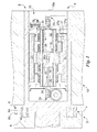
- a balancing device for a rotating body is globally denoted by reference numeral 1.
- the balancing device 1 is suitable to be used in a tool, more preferably a grinding machine and more specifically, to be associated to a grinding wheel constituting the rotating body 10, so as to measure and cancel out its unbalance during rotation.
- the rotating body 10 or tool is itself part of a machine tool 20 comprising a rotating portion 21, including the rotating body 10, a fixed portion 22 and a control unit ( Fig. 3 ).
- the balancing device 1 preferably comprises unbalance detectors 5 suitable to measure the vibrations caused by the unbalances of the rotating body 10. These preferably comprise a plurality and preferably two vibration detectors 5a. They are preferably reciprocally distanced, in particular reciprocally distanced along the rotation axis 10a, and preferably placed in correspondence with the fixed portion 22. The vibration detectors 5a are appropriately and electrically connected to the control unit 23 by cables and the like.
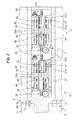
- the balancing device 1 preferably comprises then a plurality of and preferably two balancing heads 30, suitable to re-equilibrate the rotating body 10 depending on the unbalance measured by the unbalance detectors 5.
- Said heads 30 are preferably aligned along the rotation axis 10a and may be in reciprocal contact, and thus distanced by a distance defined by the outer dimensions of the heads 30, or distanced from each other.
- the unbalance detectors 5, and in particular the vibration detectors 5a may consist of any sensor, appropriately a piezoelectric sensor, suitable to measure the unbalance of the rotating body 10.
- each vibration detector 5a can be identified in the sensor described in the Patent EP-A-1645362 (paragraphs [0031]-[0082], Fig. 1 and Figs. 5-10 ) owned by the same applicant.
- the balancing head 30 is similar to the balancing heads described in Patents EP-A-0409050 (from column 3 line 34 to column 5 line 53 and Figs. 1-3 ) or IT-A-MI5081953 (from page 3 line 12 to page 8 line 8 and Figs. 1 , 2a and 2b ), both owned by the same applicant.
- the balancing masses 31 of different balancing heads 30 are thus reciprocally distanced along the rotation axis 10a, that is to say do not have barycentres coinciding along such axis.
- the balancing masses 31 belonging to the same balancing heads 30 instead appropriately have the same position of the barycentre along the rotation axis 10a.
- At least one data line 380 and at least one power supply line 381 are present for each motor 32.
- the data line 380 is suitable to transmit data signals, thus generally low power signals, while the power supply line 381 is suitable to transmit the electric power for functioning of the motors 32.
- the term network is taken to mean that a common line is present which is branched in correspondence with several motors 32.
- the balancing masses 31 are substantially the same and preferably have a profile in the shape of an arc of circumference, substantially centred on the rotation axis 10a. They are suitable to be translated along a movement circumference substantially concentric to the rotation axis 10a and lying on a plane substantially perpendicular to the rotation axis 10a.
- the transmission mechanism 33 in itself known, defines a transmission ratio among balancing masses 31 and motors 32, substantially comprised between 1/8000 and 1/15000 and, preferably substantially equal to 1/10000.
- each balancing head 30 comprises, in addition to the aforesaid components, at least one position sensor 34 suitable to monitor the position of the balancing masses 31; and at least one electronic control card 35 suitable to transmit the signals coming from and preferably also reaching the motors 32 described below.
- the term electronic control card 35 is taken to mean an electronic circuit or other electronic means in themselves known and described further below.
- the position sensor 34 is suitable to detect the absolute position of each single balancing mass 31 along the movement circumference so as to permit the motors 32 to control the reciprocal movement of the masses 31 along said circumference, as a function both of their initial position and of the unbalance of the rotating body 10, as detected by the vibration detectors 5a.
- each single motor 32, functionalanally connected to a single balancing mass 31 entails the passage to the electronics of a large number of electric wires, preferably between six and twelve and more preferably nine.
- the electronic control card 35 is preferably suitable to convert the received signals from analogue to digital, preferably all the signals.
- the digital signal thus groups the information coming from all the sensors relative to the single motor 32 or to the single mass 31 into a single encoded signal, namely the information from the position sensors 34 preferably composed of the displacement sensor 36 and also of the reference sensors 37.
- the digital signal in output from the electronic control card 35 and directed to the control unit 23 is transmitted to the data line 380, preferably composed of two electric wires inside and in output from the rotation portion 2.
- the electronic control card 35 is easy to make for a person skilled in the art given his general know-how.
- the balancing device 1 comprises detection means 6 , suitable to measure the angular position ⁇ of the rotating body 10 with respect to the fixed portion 22 around said rotation axis 10a, in particular during the performance of processing.
- detection means 6 comprise at least one magnet 6a, selectively connected to the rotating portion 2 or to the fixed portion 3, and one Hall sensor 6b or other similar sensor suitable to detect said magnetic field and selectively placed in front of the magnet 6a on the fixed portion 3 or on the rotating portion 2.
- the detection means 6 comprise two magnets 6a symmetrically placed with respect to the rotation axis 10a and connected to the rotating portion 2 so as to face the fixed portion 3 and one Hall sensor 6b connected to the fixed portion 3 and facing the rotating portion 2.
- the functioning of the balancing device 1 defines a novel balancing process for a rotating body 10.
- each balancing head 30 creates an unbalance modifying, by a known measure, the position of the balancing mass 31 along the circumference of movement, while the position sensor 34 identifies the position of said masses 31.
- the entity and position of the unbalances is thus measured directly by means of direct measurement and the positions of the balancing masses 31 and entity thereof is measured precisely. Such measurement is preferably performed by the position sensor 34.
- the unbalance detectors 5 and in particular each single vibration detector 5a measures the vibrations caused by such unbalances and may perform a precise correlation and one-to-one correspondence between vibrations measured and entity and position of the unbalance.
- the calibration phase is periodically performed, in particular when the speed of rotation is varied following the wear of the tool.
- the unbalances are detected and correlated to the vibrations measured along the axial and circumferential positions of the rotating portion 21 and of the connected rotating body 10.
- the balancing device 1 measures the vibrations caused by the unbalance of the rotating portion 21 and of the connected rotating body 10 by the detectors 5 and in particular by the vibration detectors 5a.
- the vibrations measured are precisely correlated to the unbalances of the rotating portion 21, the entity and axial and circumferential position of which is accurately calculated, preferably with reference to the fixed portion 22, thanks to the calibration phase described.
- control unit 23 calculates the position of the masses 31 of the balancing heads 30 needed to cancel out the unbalances measured and preferably simultaneously controls all the said heads so that said masses 31 are consequently moved, re-balancing the unbalances in axial and circumferential directions, and thus re-balancing the dynamic and/or rotational unbalances of the rotating portion 21 and of the connected rotating body 10.
- the invention achieves some important advantages.
- the solution of arranging the data lines 380 and/or power supply lines 381 in a network makes it possible to reduce the number of electric wires present.
- the novel solution of providing the electronics of the rotating portion 2 not grouped into a single component but divided into several electronic control cards 35 each serving a motor 32 makes it possible to have a data line 380, or in any case fewer electric lines inside said rotating portion 2.
- a first important advantage is that the device 1 is able to balance the dynamic unbalances.
- the device 1 by knowing at any time the position of the balancing masses 31, is able to easily identify how to move said masses.
- Such capacity is further enhanced by the fact that, thanks to the detection means 6, the device 1 and process, by detecting the angular position ⁇ of the rotating body 10, identify the position which the balancing masses 31 must adopt in order to cancel out the unbalance.
- Another advantage is that, due to the presence of the position sensor 34 and furthermore, of the detection means 6, the balancing device 1 and process cancel out the unbalance in extremely short times.
- Another important advantage is that, thanks to a reduced transmission ratio between the motors 32 and the masses 31, the device 1 performs a particularly precise positioning of the masses 31 and is thus able to ensure an almost total cancellation of the unbalance of the rotating body 10.
Landscapes
- Engineering & Computer Science (AREA)
- Mechanical Engineering (AREA)
- Physics & Mathematics (AREA)
- General Engineering & Computer Science (AREA)
- General Physics & Mathematics (AREA)
- Acoustics & Sound (AREA)
- Aviation & Aerospace Engineering (AREA)
- Testing Of Balance (AREA)
Priority Applications (6)
| Application Number | Priority Date | Filing Date | Title |
|---|---|---|---|
| EP14163957.5A EP2930489B1 (de) | 2014-04-09 | 2014-04-09 | Auswuchtsystem und Auswuchtverfahren für ein drehbares Objekt |
| JP2015075796A JP2015200650A (ja) | 2014-04-09 | 2015-04-02 | 回転体の動的なバランスプロセス及び装置 |
| US14/679,317 US9505104B2 (en) | 2014-04-09 | 2015-04-06 | Dynamic balancing process and device for a rotating body |
| RU2015112627A RU2015112627A (ru) | 2014-04-09 | 2015-04-07 | Способ и устройство для динамической балансировки вращающегося тела |
| BR102015007889A BR102015007889A2 (pt) | 2014-04-09 | 2015-04-08 | processo e dispositivo de balanceamento dinâmico para um corpo rotativo |
| CN201510163161.7A CN104977127A (zh) | 2014-04-09 | 2015-04-08 | 旋转体的动态平衡方法和装置 |
Applications Claiming Priority (1)
| Application Number | Priority Date | Filing Date | Title |
|---|---|---|---|
| EP14163957.5A EP2930489B1 (de) | 2014-04-09 | 2014-04-09 | Auswuchtsystem und Auswuchtverfahren für ein drehbares Objekt |
Publications (2)
| Publication Number | Publication Date |
|---|---|
| EP2930489A1 true EP2930489A1 (de) | 2015-10-14 |
| EP2930489B1 EP2930489B1 (de) | 2019-08-28 |
Family
ID=50693428
Family Applications (1)
| Application Number | Title | Priority Date | Filing Date |
|---|---|---|---|
| EP14163957.5A Active EP2930489B1 (de) | 2014-04-09 | 2014-04-09 | Auswuchtsystem und Auswuchtverfahren für ein drehbares Objekt |
Country Status (6)
| Country | Link |
|---|---|
| US (1) | US9505104B2 (de) |
| EP (1) | EP2930489B1 (de) |
| JP (1) | JP2015200650A (de) |
| CN (1) | CN104977127A (de) |
| BR (1) | BR102015007889A2 (de) |
| RU (1) | RU2015112627A (de) |
Cited By (1)
| Publication number | Priority date | Publication date | Assignee | Title |
|---|---|---|---|---|
| CN113001336A (zh) * | 2021-04-01 | 2021-06-22 | 王刚 | 一种具有砂轮动平衡校准功能的数控磨床及其使用方法 |
Families Citing this family (4)
| Publication number | Priority date | Publication date | Assignee | Title |
|---|---|---|---|---|
| CN109029689B (zh) * | 2018-08-08 | 2020-05-22 | 中国大唐集团科学技术研究院有限公司华中分公司 | 一种基于转子两端运动轨迹的旋转机械振动分析方法 |
| IT201800009107A1 (it) * | 2018-10-02 | 2020-04-02 | Balance Systems Srl | Dispositivo e procedimento di equilibratura per corpo rotante |
| EP3974797B1 (de) * | 2020-09-28 | 2023-09-06 | Balance Systems S.r.L. | Messgerät zur messung von unwuchten |
| CN118633017A (zh) * | 2022-01-31 | 2024-09-10 | 株式会社东京精密 | 自动平衡器 |
Citations (4)
| Publication number | Priority date | Publication date | Assignee | Title |
|---|---|---|---|---|
| US3371450A (en) * | 1965-10-13 | 1968-03-05 | Farrel Corp | Apparatus for balancing rotating bodies |
| EP0409050A2 (de) | 1989-07-20 | 1991-01-23 | BALANCE SYSTEMS S.r.l. | Vorrichtung zum Auswuchten einer sich drehenden Masse, insbesondere für Schleifscheiben |
| EP1645362A1 (de) | 2004-07-20 | 2006-04-12 | BALANCE SYSTEMS S.p.A. | Gerät zur Detektion von Werkzeugmaschineschwingung |
| US20140094091A1 (en) * | 2012-10-02 | 2014-04-03 | Balance Systems S.R.L. | Balancing process and device for a rotating body |
Family Cites Families (13)
| Publication number | Priority date | Publication date | Assignee | Title |
|---|---|---|---|---|
| JPS4946029B1 (de) * | 1970-06-30 | 1974-12-07 | ||
| DE2137901C3 (de) * | 1971-07-29 | 1978-04-27 | Schaudt Maschinenbau Gmbh, 7000 Stuttgart | Vorrichtung zum Feinauswuchten von Schleifscheiben |
| DE2148832C3 (de) * | 1971-09-30 | 1979-03-01 | Werner 4600 Dortmund- Aplerbeck Liebmann | Vorrichtung zum Auswuchten von umlaufenden Körpern |
| IT1258192B (it) * | 1992-08-03 | 1996-02-21 | Marposs Spa | Dispositivo di equilibratura dinamica di un corpo rotante |
| JPH07222456A (ja) * | 1994-01-31 | 1995-08-18 | Meidensha Corp | インバータ・システム |
| JPH08237994A (ja) * | 1995-02-28 | 1996-09-13 | Mitsubishi Heavy Ind Ltd | サーボ制御装置 |
| FR2754866B1 (fr) * | 1996-10-21 | 1999-01-29 | Abb Solyvent Ventec | Dispositif d'equilibrage dynamique et ponderal pour machines a rotors, en particulier pour ventilateurs industriels |
| JP2002175103A (ja) * | 2000-12-06 | 2002-06-21 | Oriental Motor Co Ltd | モータ等の制御ユニットとデジタル通信路とを接続するコネクタ装置 |
| JP2002345252A (ja) * | 2001-05-17 | 2002-11-29 | Meidensha Corp | 複数台の電力変換装置の運転方法とその装置 |
| JP2005218240A (ja) * | 2004-01-30 | 2005-08-11 | Tamagawa Seiki Co Ltd | モータコントローラシステムおよびモータシステム |
| IL179666A0 (en) * | 2006-11-28 | 2007-05-15 | Yefim Kereth | Torque-balancing differential mechanism |
| GB2449427B (en) * | 2007-05-19 | 2012-09-26 | Converteam Technology Ltd | Control methods for the synchronisation and phase shift of the pulse width modulation (PWM) strategy of power converters |
| JP2012029508A (ja) * | 2010-07-26 | 2012-02-09 | Tamagawa Seiki Co Ltd | アクチュエータコントロールシステムおよびアクチュエータシステム |
-
2014
- 2014-04-09 EP EP14163957.5A patent/EP2930489B1/de active Active
-
2015
- 2015-04-02 JP JP2015075796A patent/JP2015200650A/ja active Pending
- 2015-04-06 US US14/679,317 patent/US9505104B2/en active Active
- 2015-04-07 RU RU2015112627A patent/RU2015112627A/ru not_active Application Discontinuation
- 2015-04-08 CN CN201510163161.7A patent/CN104977127A/zh active Pending
- 2015-04-08 BR BR102015007889A patent/BR102015007889A2/pt not_active Application Discontinuation
Patent Citations (4)
| Publication number | Priority date | Publication date | Assignee | Title |
|---|---|---|---|---|
| US3371450A (en) * | 1965-10-13 | 1968-03-05 | Farrel Corp | Apparatus for balancing rotating bodies |
| EP0409050A2 (de) | 1989-07-20 | 1991-01-23 | BALANCE SYSTEMS S.r.l. | Vorrichtung zum Auswuchten einer sich drehenden Masse, insbesondere für Schleifscheiben |
| EP1645362A1 (de) | 2004-07-20 | 2006-04-12 | BALANCE SYSTEMS S.p.A. | Gerät zur Detektion von Werkzeugmaschineschwingung |
| US20140094091A1 (en) * | 2012-10-02 | 2014-04-03 | Balance Systems S.R.L. | Balancing process and device for a rotating body |
Cited By (1)
| Publication number | Priority date | Publication date | Assignee | Title |
|---|---|---|---|---|
| CN113001336A (zh) * | 2021-04-01 | 2021-06-22 | 王刚 | 一种具有砂轮动平衡校准功能的数控磨床及其使用方法 |
Also Published As
| Publication number | Publication date |
|---|---|
| US9505104B2 (en) | 2016-11-29 |
| JP2015200650A (ja) | 2015-11-12 |
| RU2015112627A (ru) | 2016-10-27 |
| CN104977127A (zh) | 2015-10-14 |
| EP2930489B1 (de) | 2019-08-28 |
| BR102015007889A2 (pt) | 2016-09-06 |
| US20150290772A1 (en) | 2015-10-15 |
Similar Documents
| Publication | Publication Date | Title |
|---|---|---|
| US10052740B2 (en) | Dynamic balancing process and device for a rotating body | |
| US9505104B2 (en) | Dynamic balancing process and device for a rotating body | |
| US10731466B2 (en) | Balancing device for a rotor including multidirectional balancing tools | |
| US9714881B2 (en) | Method and device for determining a machining axis | |
| US2331733A (en) | Unbalance correction method and machine | |
| EP3919885A1 (de) | Auswuchtvorrichtung für rotierende teile | |
| CN110546463A (zh) | 用于确定旋转构件、尤其用于车辆的离合器操纵系统的电动机的角位置的方法 | |
| CN106871850A (zh) | 角度测量装置和用于运行角度测量装置的方法 | |
| US20170123007A1 (en) | Method and apparatus for detecting interturn faults, and electrical machine | |
| CN109194040A (zh) | 一种非接触式转矩测量装置 | |
| US4608867A (en) | Method for the dynamic balancing of rotating machines in assembled condition | |
| EP3869173A1 (de) | Auswuchtgerät für rotierende teile | |
| JP2634854B2 (ja) | 研削砥石の動バランス取り方法 | |
| IT202000013102A1 (it) | Dispositivo equilibratore per pezzi in rotazione | |
| IT202000015742A1 (it) | Dispositivo equilibratore per pezzi in rotazione | |
| CN116765954A (zh) | 用于曲轴磨床的偏心校准系统 | |
| TW201408424A (zh) | 加工機的動平衡刀把及其動平衡控制系統 | |
| WO2003100374A1 (en) | System and method for balancing a rotating structure |
Legal Events
| Date | Code | Title | Description |
|---|---|---|---|
| PUAI | Public reference made under article 153(3) epc to a published international application that has entered the european phase |
Free format text: ORIGINAL CODE: 0009012 |
|
| AK | Designated contracting states |
Kind code of ref document: A1 Designated state(s): AL AT BE BG CH CY CZ DE DK EE ES FI FR GB GR HR HU IE IS IT LI LT LU LV MC MK MT NL NO PL PT RO RS SE SI SK SM TR |
|
| AX | Request for extension of the european patent |
Extension state: BA ME |
|
| 17P | Request for examination filed |
Effective date: 20160405 |
|
| RBV | Designated contracting states (corrected) |
Designated state(s): AL AT BE BG CH CY CZ DE DK EE ES FI FR GB GR HR HU IE IS IT LI LT LU LV MC MK MT NL NO PL PT RO RS SE SI SK SM TR |
|
| STAA | Information on the status of an ep patent application or granted ep patent |
Free format text: STATUS: EXAMINATION IS IN PROGRESS |
|
| 17Q | First examination report despatched |
Effective date: 20181015 |
|
| REG | Reference to a national code |
Ref country code: DE Ref legal event code: R079 Ref document number: 602014052403 Country of ref document: DE Free format text: PREVIOUS MAIN CLASS: G01M0001360000 Ipc: B24D0005160000 |
|
| RIC1 | Information provided on ipc code assigned before grant |
Ipc: G01M 1/36 20060101ALI20190206BHEP Ipc: B24D 5/16 20060101AFI20190206BHEP Ipc: F16F 15/36 20060101ALI20190206BHEP |
|
| GRAP | Despatch of communication of intention to grant a patent |
Free format text: ORIGINAL CODE: EPIDOSNIGR1 |
|
| STAA | Information on the status of an ep patent application or granted ep patent |
Free format text: STATUS: GRANT OF PATENT IS INTENDED |
|
| INTG | Intention to grant announced |
Effective date: 20190322 |
|
| GRAS | Grant fee paid |
Free format text: ORIGINAL CODE: EPIDOSNIGR3 |
|
| GRAA | (expected) grant |
Free format text: ORIGINAL CODE: 0009210 |
|
| STAA | Information on the status of an ep patent application or granted ep patent |
Free format text: STATUS: THE PATENT HAS BEEN GRANTED |
|
| AK | Designated contracting states |
Kind code of ref document: B1 Designated state(s): AL AT BE BG CH CY CZ DE DK EE ES FI FR GB GR HR HU IE IS IT LI LT LU LV MC MK MT NL NO PL PT RO RS SE SI SK SM TR |
|
| REG | Reference to a national code |
Ref country code: GB Ref legal event code: FG4D |
|
| REG | Reference to a national code |
Ref country code: CH Ref legal event code: EP |
|
| REG | Reference to a national code |
Ref country code: AT Ref legal event code: REF Ref document number: 1171810 Country of ref document: AT Kind code of ref document: T Effective date: 20190915 |
|
| REG | Reference to a national code |
Ref country code: IE Ref legal event code: FG4D |
|
| REG | Reference to a national code |
Ref country code: DE Ref legal event code: R096 Ref document number: 602014052403 Country of ref document: DE |
|
| REG | Reference to a national code |
Ref country code: NL Ref legal event code: MP Effective date: 20190828 |
|
| REG | Reference to a national code |
Ref country code: LT Ref legal event code: MG4D |
|
| PG25 | Lapsed in a contracting state [announced via postgrant information from national office to epo] |
Ref country code: LT Free format text: LAPSE BECAUSE OF FAILURE TO SUBMIT A TRANSLATION OF THE DESCRIPTION OR TO PAY THE FEE WITHIN THE PRESCRIBED TIME-LIMIT Effective date: 20190828 Ref country code: NL Free format text: LAPSE BECAUSE OF FAILURE TO SUBMIT A TRANSLATION OF THE DESCRIPTION OR TO PAY THE FEE WITHIN THE PRESCRIBED TIME-LIMIT Effective date: 20190828 Ref country code: BG Free format text: LAPSE BECAUSE OF FAILURE TO SUBMIT A TRANSLATION OF THE DESCRIPTION OR TO PAY THE FEE WITHIN THE PRESCRIBED TIME-LIMIT Effective date: 20191128 Ref country code: NO Free format text: LAPSE BECAUSE OF FAILURE TO SUBMIT A TRANSLATION OF THE DESCRIPTION OR TO PAY THE FEE WITHIN THE PRESCRIBED TIME-LIMIT Effective date: 20191128 Ref country code: SE Free format text: LAPSE BECAUSE OF FAILURE TO SUBMIT A TRANSLATION OF THE DESCRIPTION OR TO PAY THE FEE WITHIN THE PRESCRIBED TIME-LIMIT Effective date: 20190828 Ref country code: HR Free format text: LAPSE BECAUSE OF FAILURE TO SUBMIT A TRANSLATION OF THE DESCRIPTION OR TO PAY THE FEE WITHIN THE PRESCRIBED TIME-LIMIT Effective date: 20190828 Ref country code: PT Free format text: LAPSE BECAUSE OF FAILURE TO SUBMIT A TRANSLATION OF THE DESCRIPTION OR TO PAY THE FEE WITHIN THE PRESCRIBED TIME-LIMIT Effective date: 20191230 Ref country code: FI Free format text: LAPSE BECAUSE OF FAILURE TO SUBMIT A TRANSLATION OF THE DESCRIPTION OR TO PAY THE FEE WITHIN THE PRESCRIBED TIME-LIMIT Effective date: 20190828 |
|
| PG25 | Lapsed in a contracting state [announced via postgrant information from national office to epo] |
Ref country code: RS Free format text: LAPSE BECAUSE OF FAILURE TO SUBMIT A TRANSLATION OF THE DESCRIPTION OR TO PAY THE FEE WITHIN THE PRESCRIBED TIME-LIMIT Effective date: 20190828 Ref country code: IS Free format text: LAPSE BECAUSE OF FAILURE TO SUBMIT A TRANSLATION OF THE DESCRIPTION OR TO PAY THE FEE WITHIN THE PRESCRIBED TIME-LIMIT Effective date: 20191228 Ref country code: GR Free format text: LAPSE BECAUSE OF FAILURE TO SUBMIT A TRANSLATION OF THE DESCRIPTION OR TO PAY THE FEE WITHIN THE PRESCRIBED TIME-LIMIT Effective date: 20191129 Ref country code: AL Free format text: LAPSE BECAUSE OF FAILURE TO SUBMIT A TRANSLATION OF THE DESCRIPTION OR TO PAY THE FEE WITHIN THE PRESCRIBED TIME-LIMIT Effective date: 20190828 Ref country code: ES Free format text: LAPSE BECAUSE OF FAILURE TO SUBMIT A TRANSLATION OF THE DESCRIPTION OR TO PAY THE FEE WITHIN THE PRESCRIBED TIME-LIMIT Effective date: 20190828 Ref country code: LV Free format text: LAPSE BECAUSE OF FAILURE TO SUBMIT A TRANSLATION OF THE DESCRIPTION OR TO PAY THE FEE WITHIN THE PRESCRIBED TIME-LIMIT Effective date: 20190828 |
|
| REG | Reference to a national code |
Ref country code: AT Ref legal event code: MK05 Ref document number: 1171810 Country of ref document: AT Kind code of ref document: T Effective date: 20190828 |
|
| PG25 | Lapsed in a contracting state [announced via postgrant information from national office to epo] |
Ref country code: TR Free format text: LAPSE BECAUSE OF FAILURE TO SUBMIT A TRANSLATION OF THE DESCRIPTION OR TO PAY THE FEE WITHIN THE PRESCRIBED TIME-LIMIT Effective date: 20190828 |
|
| PG25 | Lapsed in a contracting state [announced via postgrant information from national office to epo] |
Ref country code: RO Free format text: LAPSE BECAUSE OF FAILURE TO SUBMIT A TRANSLATION OF THE DESCRIPTION OR TO PAY THE FEE WITHIN THE PRESCRIBED TIME-LIMIT Effective date: 20190828 Ref country code: AT Free format text: LAPSE BECAUSE OF FAILURE TO SUBMIT A TRANSLATION OF THE DESCRIPTION OR TO PAY THE FEE WITHIN THE PRESCRIBED TIME-LIMIT Effective date: 20190828 Ref country code: DK Free format text: LAPSE BECAUSE OF FAILURE TO SUBMIT A TRANSLATION OF THE DESCRIPTION OR TO PAY THE FEE WITHIN THE PRESCRIBED TIME-LIMIT Effective date: 20190828 Ref country code: EE Free format text: LAPSE BECAUSE OF FAILURE TO SUBMIT A TRANSLATION OF THE DESCRIPTION OR TO PAY THE FEE WITHIN THE PRESCRIBED TIME-LIMIT Effective date: 20190828 Ref country code: PL Free format text: LAPSE BECAUSE OF FAILURE TO SUBMIT A TRANSLATION OF THE DESCRIPTION OR TO PAY THE FEE WITHIN THE PRESCRIBED TIME-LIMIT Effective date: 20190828 |
|
| PG25 | Lapsed in a contracting state [announced via postgrant information from national office to epo] |
Ref country code: SK Free format text: LAPSE BECAUSE OF FAILURE TO SUBMIT A TRANSLATION OF THE DESCRIPTION OR TO PAY THE FEE WITHIN THE PRESCRIBED TIME-LIMIT Effective date: 20190828 Ref country code: CZ Free format text: LAPSE BECAUSE OF FAILURE TO SUBMIT A TRANSLATION OF THE DESCRIPTION OR TO PAY THE FEE WITHIN THE PRESCRIBED TIME-LIMIT Effective date: 20190828 Ref country code: IS Free format text: LAPSE BECAUSE OF FAILURE TO SUBMIT A TRANSLATION OF THE DESCRIPTION OR TO PAY THE FEE WITHIN THE PRESCRIBED TIME-LIMIT Effective date: 20200224 Ref country code: SM Free format text: LAPSE BECAUSE OF FAILURE TO SUBMIT A TRANSLATION OF THE DESCRIPTION OR TO PAY THE FEE WITHIN THE PRESCRIBED TIME-LIMIT Effective date: 20190828 |
|
| REG | Reference to a national code |
Ref country code: DE Ref legal event code: R097 Ref document number: 602014052403 Country of ref document: DE |
|
| PLBE | No opposition filed within time limit |
Free format text: ORIGINAL CODE: 0009261 |
|
| STAA | Information on the status of an ep patent application or granted ep patent |
Free format text: STATUS: NO OPPOSITION FILED WITHIN TIME LIMIT |
|
| PG2D | Information on lapse in contracting state deleted |
Ref country code: IS |
|
| 26N | No opposition filed |
Effective date: 20200603 |
|
| PG25 | Lapsed in a contracting state [announced via postgrant information from national office to epo] |
Ref country code: SI Free format text: LAPSE BECAUSE OF FAILURE TO SUBMIT A TRANSLATION OF THE DESCRIPTION OR TO PAY THE FEE WITHIN THE PRESCRIBED TIME-LIMIT Effective date: 20190828 |
|
| PG25 | Lapsed in a contracting state [announced via postgrant information from national office to epo] |
Ref country code: CY Free format text: LAPSE BECAUSE OF FAILURE TO SUBMIT A TRANSLATION OF THE DESCRIPTION OR TO PAY THE FEE WITHIN THE PRESCRIBED TIME-LIMIT Effective date: 20190828 |
|
| PG25 | Lapsed in a contracting state [announced via postgrant information from national office to epo] |
Ref country code: MK Free format text: LAPSE BECAUSE OF FAILURE TO SUBMIT A TRANSLATION OF THE DESCRIPTION OR TO PAY THE FEE WITHIN THE PRESCRIBED TIME-LIMIT Effective date: 20190828 |
|
| P01 | Opt-out of the competence of the unified patent court (upc) registered |
Effective date: 20230531 |
|
| PGFP | Annual fee paid to national office [announced via postgrant information from national office to epo] |
Ref country code: LU Payment date: 20240418 Year of fee payment: 11 |
|
| PGFP | Annual fee paid to national office [announced via postgrant information from national office to epo] |
Ref country code: IE Payment date: 20240418 Year of fee payment: 11 |
|
| PGFP | Annual fee paid to national office [announced via postgrant information from national office to epo] |
Ref country code: GB Payment date: 20240423 Year of fee payment: 11 |
|
| PGFP | Annual fee paid to national office [announced via postgrant information from national office to epo] |
Ref country code: DE Payment date: 20240418 Year of fee payment: 11 |
|
| PGFP | Annual fee paid to national office [announced via postgrant information from national office to epo] |
Ref country code: MC Payment date: 20240418 Year of fee payment: 11 |
|
| PGFP | Annual fee paid to national office [announced via postgrant information from national office to epo] |
Ref country code: CH Payment date: 20240501 Year of fee payment: 11 |
|
| PGFP | Annual fee paid to national office [announced via postgrant information from national office to epo] |
Ref country code: IT Payment date: 20240404 Year of fee payment: 11 Ref country code: FR Payment date: 20240422 Year of fee payment: 11 |
|
| PGFP | Annual fee paid to national office [announced via postgrant information from national office to epo] |
Ref country code: MT Payment date: 20240426 Year of fee payment: 11 Ref country code: BE Payment date: 20240419 Year of fee payment: 11 |