EP2930378B2 - Spacer fixing element - Google Patents
Spacer fixing element Download PDFInfo
- Publication number
- EP2930378B2 EP2930378B2 EP14164469.0A EP14164469A EP2930378B2 EP 2930378 B2 EP2930378 B2 EP 2930378B2 EP 14164469 A EP14164469 A EP 14164469A EP 2930378 B2 EP2930378 B2 EP 2930378B2
- Authority
- EP
- European Patent Office
- Prior art keywords
- component
- threaded portion
- thread
- fixing element
- rotation
- Prior art date
- Legal status (The legal status is an assumption and is not a legal conclusion. Google has not performed a legal analysis and makes no representation as to the accuracy of the status listed.)
- Active
Links
- 125000006850 spacer group Chemical group 0.000 title claims description 64
- 239000002131 composite material Substances 0.000 claims description 8
- 238000000034 method Methods 0.000 claims description 5
- 230000035515 penetration Effects 0.000 claims description 3
- 238000010079 rubber tapping Methods 0.000 claims 1
- 230000007704 transition Effects 0.000 claims 1
- 238000005553 drilling Methods 0.000 description 10
- ORQBXQOJMQIAOY-UHFFFAOYSA-N nobelium Chemical compound [No] ORQBXQOJMQIAOY-UHFFFAOYSA-N 0.000 description 5
- 239000002184 metal Substances 0.000 description 4
- 230000000149 penetrating effect Effects 0.000 description 3
- 238000011161 development Methods 0.000 description 2
- 230000018109 developmental process Effects 0.000 description 2
- 239000011810 insulating material Substances 0.000 description 2
- 238000004519 manufacturing process Methods 0.000 description 2
- 238000005253 cladding Methods 0.000 description 1
- 230000006835 compression Effects 0.000 description 1
- 238000007906 compression Methods 0.000 description 1
- 230000001419 dependent effect Effects 0.000 description 1
Images
Classifications
-
- F—MECHANICAL ENGINEERING; LIGHTING; HEATING; WEAPONS; BLASTING
- F16—ENGINEERING ELEMENTS AND UNITS; GENERAL MEASURES FOR PRODUCING AND MAINTAINING EFFECTIVE FUNCTIONING OF MACHINES OR INSTALLATIONS; THERMAL INSULATION IN GENERAL
- F16B—DEVICES FOR FASTENING OR SECURING CONSTRUCTIONAL ELEMENTS OR MACHINE PARTS TOGETHER, e.g. NAILS, BOLTS, CIRCLIPS, CLAMPS, CLIPS OR WEDGES; JOINTS OR JOINTING
- F16B25/00—Screws that cut thread in the body into which they are screwed, e.g. wood screws
- F16B25/001—Screws that cut thread in the body into which they are screwed, e.g. wood screws characterised by the material of the body into which the screw is screwed
- F16B25/0021—Screws that cut thread in the body into which they are screwed, e.g. wood screws characterised by the material of the body into which the screw is screwed the material being metal, e.g. sheet-metal or aluminium
-
- F—MECHANICAL ENGINEERING; LIGHTING; HEATING; WEAPONS; BLASTING
- F16—ENGINEERING ELEMENTS AND UNITS; GENERAL MEASURES FOR PRODUCING AND MAINTAINING EFFECTIVE FUNCTIONING OF MACHINES OR INSTALLATIONS; THERMAL INSULATION IN GENERAL
- F16B—DEVICES FOR FASTENING OR SECURING CONSTRUCTIONAL ELEMENTS OR MACHINE PARTS TOGETHER, e.g. NAILS, BOLTS, CIRCLIPS, CLAMPS, CLIPS OR WEDGES; JOINTS OR JOINTING
- F16B25/00—Screws that cut thread in the body into which they are screwed, e.g. wood screws
- F16B25/0036—Screws that cut thread in the body into which they are screwed, e.g. wood screws characterised by geometric details of the screw
- F16B25/0042—Screws that cut thread in the body into which they are screwed, e.g. wood screws characterised by geometric details of the screw characterised by the geometry of the thread, the thread being a ridge wrapped around the shaft of the screw
- F16B25/0057—Screws that cut thread in the body into which they are screwed, e.g. wood screws characterised by geometric details of the screw characterised by the geometry of the thread, the thread being a ridge wrapped around the shaft of the screw the screw having distinct axial zones, e.g. multiple axial thread sections with different pitch or thread cross-sections
- F16B25/0063—Screws that cut thread in the body into which they are screwed, e.g. wood screws characterised by geometric details of the screw characterised by the geometry of the thread, the thread being a ridge wrapped around the shaft of the screw the screw having distinct axial zones, e.g. multiple axial thread sections with different pitch or thread cross-sections with a non-threaded portion on the shaft of the screw
-
- F—MECHANICAL ENGINEERING; LIGHTING; HEATING; WEAPONS; BLASTING
- F16—ENGINEERING ELEMENTS AND UNITS; GENERAL MEASURES FOR PRODUCING AND MAINTAINING EFFECTIVE FUNCTIONING OF MACHINES OR INSTALLATIONS; THERMAL INSULATION IN GENERAL
- F16B—DEVICES FOR FASTENING OR SECURING CONSTRUCTIONAL ELEMENTS OR MACHINE PARTS TOGETHER, e.g. NAILS, BOLTS, CIRCLIPS, CLAMPS, CLIPS OR WEDGES; JOINTS OR JOINTING
- F16B25/00—Screws that cut thread in the body into which they are screwed, e.g. wood screws
- F16B25/10—Screws performing an additional function to thread-forming, e.g. drill screws or self-piercing screws
- F16B25/103—Screws performing an additional function to thread-forming, e.g. drill screws or self-piercing screws by means of a drilling screw-point, i.e. with a cutting and material removing action
-
- F—MECHANICAL ENGINEERING; LIGHTING; HEATING; WEAPONS; BLASTING
- F16—ENGINEERING ELEMENTS AND UNITS; GENERAL MEASURES FOR PRODUCING AND MAINTAINING EFFECTIVE FUNCTIONING OF MACHINES OR INSTALLATIONS; THERMAL INSULATION IN GENERAL
- F16B—DEVICES FOR FASTENING OR SECURING CONSTRUCTIONAL ELEMENTS OR MACHINE PARTS TOGETHER, e.g. NAILS, BOLTS, CIRCLIPS, CLAMPS, CLIPS OR WEDGES; JOINTS OR JOINTING
- F16B5/00—Joining sheets or plates, e.g. panels, to one another or to strips or bars parallel to them
- F16B5/02—Joining sheets or plates, e.g. panels, to one another or to strips or bars parallel to them by means of fastening members using screw-thread
- F16B5/0275—Joining sheets or plates, e.g. panels, to one another or to strips or bars parallel to them by means of fastening members using screw-thread the screw-threaded element having at least two axially separated threaded portions
Definitions
- the invention relates to a spacer fastener for the spaced connection of two components, according to the preamble of claim 1.
- Generic spacer fasteners in particular screws for fixing the distance, are from DE 20 2005 005 342 U1 as well as the EP 1 034 379 B1 known.
- EP 1 235 988 B1 discloses a spacer fastener having two screw threads for screwing into two spaced components.
- a drilling element is arranged between the two threads, which has a diameter which is larger than the diameter of the thread facing the drill bit and smaller than the diameter of the thread located on the head.
- a spacer fastening element can be introduced without pre-drilling the sheet metal part.
- the drilling element forms a stop on the second component insofar as there is a thread-free part between the drilling element and the threaded section facing the tip, in which the second component comes to rest and in which the spacer fastening element rotates without propulsion.
- the drilling element is intended to serve as a stop on the second component.
- a spacer fastener for mounting a first component at a distance from a second component, comprises a head which merges into a shank which in turn ends in a self-drilling point. After the tip, in the direction of the head, a threaded section is provided which has a thread with a first direction of rotation, wherein a hole can be made in the first component with rotation in the first direction of rotation, through which the first threaded section is passed. Furthermore, following the first threaded section, a stop element is provided, which forms a stop on the second component when rotated in the first direction of rotation.
- the stop element is designed as a second threaded section with a thread with a second direction of rotation opposite to the first direction of rotation, the threaded section being designed in such a way that when the spacer fastening element is rotated in the second direction of rotation, the spacer fastening element is pierced by the after the penetration of the first component by the first Threaded portion remaining hole can be screwed in the first component, after which it forms a stop under rotation in the first direction of rotation on the second component.
- the area between the end of the thread of the second threaded section facing the head and the head is designed in such a way that it can be guided through the remaining hole in the first component, at least with rotation in the first direction of rotation.
- the spacer fastening element can be screwed on easily and quickly.
- Such a spacer fastener sets a defined distance between the two components, which are in particular in the form of metal sheets.
- the distance from the end of the second threaded section facing the head to the tip is less than the distance from the end of the second threaded section facing the tip to the underside of the head. This ensures that the second threaded section completely penetrates the first component before this drill tip penetrates the second component.
- the first direction of rotation can be a right-hand rotation and accordingly the first threaded section can have a right-hand thread. Consequently, the opposite second direction of rotation is then a left-hand rotation and the second threaded section thus has a left-hand thread. This corresponds to the current standard for screw turning directions and ensures intuitive use.
- a thread-free area can be provided between the first threaded section and the second threaded section.
- the second threaded section can be spaced apart from the first threaded section, depending on the thickness of the fastening area of the second component, in such a way that after the fastening area of the second component has been completely penetrated, the first threaded section is no longer in radial engagement with the attachment portion of the second component. This ensures overtightening protection in the second component, since as soon as the first threaded section has penetrated the fastening area, the spacer fastening element is no longer advanced.
- the in particular plate-shaped fastening area then comes to rest in a thread-free area between the first threaded section and the second threaded section.
- the spacer fastening element thus encloses the fastening area with its thread ends and in this way fixes it in the axial direction in the fastening area both in the tension and in the compression direction.
- the thread of the first and/or the second threaded section be designed in such a way that this ends in a plane orthogonal to the screw axis, at least at the end facing the other thread.
- the contact surface of the first and second threaded section on the second component can be further increased in that the angle of the thread flank facing the component in its fastening position is smaller with the height of the thread than the angle of the thread flank facing away from the component.
- the end of the first threaded section facing away from the tip and the end of the second threaded section facing the tip face the component in the installed position.
- the second threaded section can preferably also have a multiple thread, in particular a double thread.
- a large number of thread ends in particular two thread ends, are provided, which support the spacer fastening element with respect to the fastening area of the second component in the pressure direction.
- the pitch of the thread in the first and second thread section is in particular identical. This ensures an even propulsion speed.
- the outer diameter of the thread of the second threaded section can be greater than or equal to the outer diameter of the first threaded section. This relationship can ensure that support in the fastening area of the second component is guaranteed in the direction of pressure.
- a third threaded section can be provided between the second threaded section and the head, which has a thread in the first direction of rotation, which acts as a supporting thread.
- This third threaded section is designed in particular in such a way that, with rotation in the first direction of rotation, it pulls the first component over the remaining hole in the direction of the head.
- a thread-free area can preferably be provided between the third threaded section and the head of the spacer fastening element.
- This thread-free area can be adapted to the first component in such a way that the fastening area of the first component comes to lie between the head and the third threaded section.
- the fastening area of the first component can be supported by the supporting thread in the thread-free area after it has been penetrated by the supporting thread.
- a thread-free part can be provided on the shaft between the second threaded section and the third threaded section.
- this relates to a composite component comprising a first component with an in particular plate-like fastening area and a second component having an in particular plate-like fastening area, these two components being connected via a spacer fastening element as described above.
- the composite component includes in particular a spacer fastener as described above, in which a thread-free area is provided between the first threaded section and the second threaded section.
- the distance between the two threaded sections preferably corresponds to the thickness of the fastening area of the second component.
- the distance between the threaded sections is in particular greater than or equal to the thickness of the fastening area of the first component.
- the fastening areas ie the areas into which the spacer fastening element is introduced, can regularly have a thickness of 0.5 mm - 2 mm for the first component and a thickness of 1 mm - 4 mm for the second component.
- a component can also consist of a combination of superimposed parts.
- the assembly of components comprises a cassette wall, with the first component acting as an upper or Outer shell, in particular a trapezoidal sheet metal outer shell, and the second component is designed as a substructure, in particular a profiled sheet metal outer cladding.
- a layer of insulating material can also be provided between the outer shell and the substructure.
- a cassette wall can be provided in a quick, simple and process-reliable manner.
- this relates to a method for producing a composite component as described above, in particular a cassette wall.
- the spacer fastening element is screwed into the first component in a first direction of rotation, then the spacer fastener is screwed through the first component in a second direction of rotation opposite the first direction of rotation and then the spacer fastener is screwed into the second component while rotating in the first direction of rotation.
- cassette wall can also be produced in this simple manner, in which an outer shell can be connected to a substructure lying behind it.
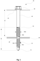
- FIG. 1 shows a spacer fastener 10 comprising a self-drilling tip 11 and a first threaded portion 12 adjoining it. Between the second threaded section 14 and the head 16 there is an unthreaded shank part 18 which has no thread.
- the first threaded section 12 is designed in such a way that it carries a right-hand thread which has the pitch DS1 and the outside diameter DA1.
- the second threaded section 14 carries a left-hand thread with an outer diameter DA2 with a pitch DS2.
- the outer diameter DA1 of the first threaded section 12 is smaller than the outer diameter DA2 of the second threaded section 14.
- the left-hand thread of the second threaded section 14 runs out at a distance in the axial direction from the right-hand thread of the first threaded section 12 .
- An unthreaded shank part 20 is located between the right-hand thread 12 and the left-hand thread 14.
- a second component 24 can be accommodated in an enclosed manner after the threaded sections 12, 14 if the spacer fastening element 10 is appropriately matched to the component assembly 22, 24.
- the first threaded section 12 is designed in such a way that, when rotated to the right, it penetrates through the hole formed by the tip 11 in the first component 22 and in the second component 24 .
- the second threaded section 14 is designed in such a way that it can be passed through the formed hole when turned to the left.
- the left-hand thread 14 forms a stop in relation to the second component 24 .
- the distance between a first component 22 and the second component 24 can be set based on the maximum distance between the underside of the head 16 and the outlet of the left-hand thread 14 on the second component 24 .
- This can preferably be influenced by elements such as washers or tension washers that can be introduced between the head 16 and the first component 22 .
- Such an execution according to 1 is particularly advantageous if a filling element is provided between the first component 22 and the second component 24, which applies a force pushing the two components 22, 24 apart.
- the pitch of the right-hand thread DS1 corresponds to the pitch of the left-hand thread DS2.
- the tip 11 forms a hole in the upper component 24, which is further widened by the subsequent first threaded section 12.
- the unthreaded shank part 20 between the first threaded section 12 and the second threaded section 14 is dimensioned such that it is greater than the thickness of the first component 22 at the point of penetration.
- the spacer fastening element 10 After penetrating the hole preformed by the tip 11 and the thread 12 in the first component 22 in a clockwise direction, the spacer fastening element 10 can be rotated in a counter-clockwise direction through the first component 22 . Due to the thread-free section 18, the spacer fastener 10 can then be pushed through the hole in the first component 22 until the drill bit 11 rests against the second component 24. A hole can then be made in the second component 24 by turning to the right, into which the spacer fastening element 10 is pulled until the second component 24 comes to rest in the thread-free region 20 between the first threaded section 12 and the second threaded section 14 .
- the spacer fastener 10 is dimensioned such that the distance A1 from the underside of the head to the end of the second threaded section 14 facing the tip 11 is greater than the section A2 from the end of the second threaded section 14 facing the head 16 to the tip 11.
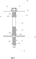
- FIG. 2 shows a spacer fastener 30 with a tip 31, a first threaded portion 32, a second threaded portion 34, a head 36, an unthreaded portion 38 which is between the second threaded portion 34 and the head 36.
- a third threaded section 40 is provided between the second threaded section 34 which is a left-hand thread and the head 36 .
- the thread 40 which has the outside diameter DA3, which corresponds to the outside diameter of the second threaded section DA2, ensures that the first component 42 is driven against the head 36 when the spacer fastening element is turned in a clockwise direction.
- the first component 42 is then held between the head 36 and the third threaded section 40, which is also referred to as the supporting thread. In this way, the distance between the first component 42 and the second component 44 can also be set precisely without prestressing between the components 42, 44.
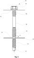
- the spacer fastener 50 likewise has a tip 51 , a first threaded section 52 , a second threaded section 54 and a head 56 .
- a thread-free part 58 is provided between the head 56 and the second threaded section 54 .
- a third threaded section 60 is also provided, which serves as a supporting thread.
- the second thread section 54 and the third thread section 60 have an angle ⁇ between the thread flank facing away from the second component 64 and the thread height in the installed position, which is smaller than the angle ⁇ that the thread flank facing away from the second component 64 forms with the thread height.
- a corresponding design is also present for the second threaded section 54 with respect to the second component 64 , which comes to rest in the thread-free area 61 .
- the thread-free area 61 is also dimensioned here in such a way that it is matched to the thickness or strength of the second component 64 in the fastening area.
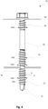
- FIG. 4 shows a further embodiment of a spacer fastening element 70.
- This also has a tip 71, a first threaded section 72, a second threaded section 74, a thread-free area 78, a head 80 and a third threaded section 82.
- a thread-free area 76 is provided between the first threaded section 72 and the second threaded section 74 .
- the outer diameters of the threads of the threaded section 72 and 74 and of the third threaded section 82 are of the same size, with the flank angle of the threaded sections being selected such that it has a smaller angle at the end facing the component and in relation to the height of the thread than on the component opposite side, similar 3 .
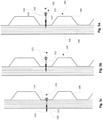
- Figures 5a to 5c show a method for producing a cassette wall 100 with an outer shell 104, a profile rail 106 and an insulating material layer 108.
- the spacer fastening element 102 has a first threaded section 110, a second threaded section 112 and a third threaded section 114.
- a washer 118 is provided under the head 116 of the spacer fastener 102 .
- the spacer fastening element 102 is first driven in a clockwise direction through the outer shell 104 in a self-drilling manner.
- the first threaded portion 110 drives the spacer fastener 102 clockwise through the hole in the outer shell 104 pre-drilled through the tip.
- first threaded portion 110 runs out.
- the left-hand thread of the second threaded section 112 then forms a stop in clockwise rotation, with the outer shell 104 temporarily coming to rest between the first threaded section 110 and the second threaded section 112 .
- the drill bit After penetrating the outer shell 104 with the second threaded section 112 in anticlockwise rotation, the drill bit rests against the profile rail 106, whereas the outer shell 104 is in the unthreaded area of the spacer fastening element 102.
- the spacer fastening element 102 is introduced into the profile rail 106 via the drill bit and the first threaded section 110 .
- the outer shell 104 also engages the third threaded portion 114 urging the outer shell 104 toward the head 116 .
- the profile rail 106 lies in the intermediate area between the first threaded section 110 and the second threaded section 112.
- This area 120 is designed without a thread and ensures that no further advance takes place after this area has been reached. Accordingly, an over-tightening protection is guaranteed.
- the outer shell 104 and the profile rail 106 are thus held at a precise distance from one another via the spacer fastening element 102 .
Description
Die Erfindung betrifft ein Distanzbefestigungselement zur distanzierten Verbindung zweier Bauteile, gemäß dem Oberbegriff des Anspruchs 1.The invention relates to a spacer fastener for the spaced connection of two components, according to the preamble of claim 1.
Gattungsgemäße Distanzbefestigungselemente, insbesondere Schrauben zur Abstandsfixierung, sind aus der
Gemäß der Lehre der
Durch Vorsehung eines solchen Bohrelements kann ein Einbringen eines Distanzbefestigungselements ohne Vorbohren des Blechteils erfolgen. Das Bohrelement bildet insoweit einen Anschlag am zweiten Bauelement, als dass zwischen dem Bohrelement und dem der Spitze zugewandten Gewindeabschnitt ein gewindefreier Teil liegt, in welchem das zweite Bauteil zu liegen kommt, und in welchem das Distanzbefestigungselement vortriebsfrei dreht. Durch Unterbindung des Vortriebs soll das Bohrelement als Anschlag am zweiten Bauteil dienen.By providing such a drilling element, a spacer fastening element can be introduced without pre-drilling the sheet metal part. The drilling element forms a stop on the second component insofar as there is a thread-free part between the drilling element and the threaded section facing the tip, in which the second component comes to rest and in which the spacer fastening element rotates without propulsion. By preventing the propulsion, the drilling element is intended to serve as a stop on the second component.
Es ist Aufgabe der Erfindung ein solches Distanzverbindungselement derart zu verbessern, dass eine höhere Prozesssicherheit gewährleistet wird.It is the object of the invention to improve such a spacer connection element in such a way that greater process reliability is ensured.
Die Aufgabe wird durch die kennzeichnenden Merkmale des Anspruchs 1 in Verbindung mit seinen Oberbegriffsmerkmalen gelöst.The object is achieved by the characterizing features of claim 1 in conjunction with its preamble features.
Die Unteransprüche bilden vorteilhafte Weiterbildungen der Erfindung.The dependent claims form advantageous developments of the invention.
In bekannter Weise umfasst ein Distanzbefestigungselement, zur Befestigung eines ersten Bauteils distanziert zu einem zweiten Bauteil, einen Kopf, der in einen Schaft übergeht, der wiederum in einer selbstbohrenden Spitze endet. Nach der Spitze, in Richtung Kopf, ist ein Gewindeabschnitt vorgesehen, der ein Gewinde mit einer ersten Drehrichtung aufweist, wobei unter Drehung in erster Drehrichtung ein Loch in das erste Bauteil eingebracht werden kann, durch welches der erste Gewindeabschnitt hindurchgeführt wird. Ferner ist nachfolgend zum ersten Gewindeabschnitt ein Anschlagelement vorgesehen, das an dem zweiten Bauteil bei Drehung in erster Drehrichtung einen Anschlag bildet.In a known manner, a spacer fastener, for mounting a first component at a distance from a second component, comprises a head which merges into a shank which in turn ends in a self-drilling point. After the tip, in the direction of the head, a threaded section is provided which has a thread with a first direction of rotation, wherein a hole can be made in the first component with rotation in the first direction of rotation, through which the first threaded section is passed. Furthermore, following the first threaded section, a stop element is provided, which forms a stop on the second component when rotated in the first direction of rotation.
Erfindungsgemäß, ist das Anschlagselement als zweiter Gewindeabschnitt mit einem Gewinde mit einer der ersten Drehrichtung entgegengesetzten zweiten Drehrichtung ausgebildet ist, wobei der Gewindeabschnitt derart gestaltet ist, dass bei Drehung in zweiter Drehrichtung des Distanzbefestigungselements das Distanzbefestigungselement durch das nach der Penetration des ersten Bauteils durch den ersten Gewindeabschnitt verbliebene Loch im ersten Bauteil geschraubt werden kann, wonach es unter Drehung in erster Drehrichtung am zweiten Bauteil einen Anschlag bildet. Ferner ist der Bereich zwischen dem dem Kopf zugewandten Auslauf des Gewindes des zweiten Gewindeabschnitts und dem Kopf derart gestaltet, dass dieser wenigstens unter Drehung in erster Drehrichtung durch das verbliebene Loch im ersten Bauteil geführt werden kann.According to the invention, the stop element is designed as a second threaded section with a thread with a second direction of rotation opposite to the first direction of rotation, the threaded section being designed in such a way that when the spacer fastening element is rotated in the second direction of rotation, the spacer fastening element is pierced by the after the penetration of the first component by the first Threaded portion remaining hole can be screwed in the first component, after which it forms a stop under rotation in the first direction of rotation on the second component. Furthermore, the area between the end of the thread of the second threaded section facing the head and the head is designed in such a way that it can be guided through the remaining hole in the first component, at least with rotation in the first direction of rotation.
Auf diese Weise kann durch einen Drehrichtungswechsel eine einfache und schnelle Verschraubung des Distanzbefestigungselements erfolgen. Durch ein derartiges Distanzbefestigungselement wird ein definierter Abstand der beiden Bauteile, die insbesondere in Form von Blechen ausgebildet sind, eingestellt.In this way, by changing the direction of rotation, the spacer fastening element can be screwed on easily and quickly. Such a spacer fastener sets a defined distance between the two components, which are in particular in the form of metal sheets.
Gemäß der Erfindung ist der Abstand des dem Kopf zugewandten Endes des zweiten Gewindeabschnitts zur Spitze geringer als der Abstand des der Spitze zugewandten Endes des zweiten Gewindeabschnitts zur Unterseite des Kopfes. Dadurch wird gewährleistet, dass der zweite Gewindeabschnitt das erste Bauteil vollständig durchdringt, bevor diese Bohrspitze in das zweite Bauteil eindringt.According to the invention, the distance from the end of the second threaded section facing the head to the tip is less than the distance from the end of the second threaded section facing the tip to the underside of the head. This ensures that the second threaded section completely penetrates the first component before this drill tip penetrates the second component.
Gemäß einer weiteren bevorzugten Ausführungsform, kann die erste Drehrichtung eine Rechtsdrehung sein und entsprechend der erste Gewindeabschnitt ein Rechtsgewinde aufweisen. Folglich ist die entgegengesetzte zweite Drehrichtung dann eine Linksdrehung und der zweite Gewindeabschnitt weist somit ein Linksgewinde auf. Dies entspricht dem gängigen Standard für Schraubendrehrichtungen und sorgt für eine intuitive Verwendung.According to a further preferred embodiment, the first direction of rotation can be a right-hand rotation and accordingly the first threaded section can have a right-hand thread. Consequently, the opposite second direction of rotation is then a left-hand rotation and the second threaded section thus has a left-hand thread. This corresponds to the current standard for screw turning directions and ensures intuitive use.
Zwischen dem ersten Gewindeabschnitt und dem zweiten Gewindeabschnitt kann ein gewindefreier Bereich vorgesehen sein. So kann, insbesondere bei Vorliegen eines plattenförmigen Befestigungsbereichs des zweiten Bauteils, der zweite Gewindeabschnitt in Abhängigkeit der Dicke des Befestigungsbereichs des zweiten Bauteils von dem ersten Gewindeabschnitt derart beabstandet sein, dass nachdem der Befestigungsbereich des zweiten Bauteils vollständig durchdrungen wurde, der erste Gewindeabschnitt nicht mehr in radialem Eingriff mit dem Befestigungsbereich des zweiten Bauteils steht. Dies sorgt für einen Überdrehschutz im zweiten Bauteil, da, sobald der erste Gewindeabschnitt den Befestigungsbereich durchdrungen hat, kein weiterer Vortrieb des Distanzbefestigungselements mehr erfolgt.A thread-free area can be provided between the first threaded section and the second threaded section. Thus, in particular if the second component has a plate-shaped fastening area, the second threaded section can be spaced apart from the first threaded section, depending on the thickness of the fastening area of the second component, in such a way that after the fastening area of the second component has been completely penetrated, the first threaded section is no longer in radial engagement with the attachment portion of the second component. This ensures overtightening protection in the second component, since as soon as the first threaded section has penetrated the fastening area, the spacer fastening element is no longer advanced.
Der insbesondere plattenförmige Befestigungsbereich kommt dann in einem gewindefreien Bereich zwischen dem ersten Gewindeabschnitt und dem zweiten Gewindeabschnitt zu liegen. Das Distanzbefestigungselement umschließt so mit seinen Gewindeausläufen den Befestigungsbereich und legt diesen in axialer Richtung auf diese Weise im Befestigungsbereich sowohl in Zug- als auch DruckRichtung fest.The in particular plate-shaped fastening area then comes to rest in a thread-free area between the first threaded section and the second threaded section. The spacer fastening element thus encloses the fastening area with its thread ends and in this way fixes it in the axial direction in the fastening area both in the tension and in the compression direction.
In einer besonders vorteilhaften Weiterbildung kann das Gewinde des ersten und/oder des zweiten Gewindeabschnitts derart ausgestaltet sein, dass dieses, wenigstens an dem dem jeweils anderen Gewinde zugewandten Ende, in einer Ebene orthogonal zur Schraubenachse ausläuft.In a particularly advantageous development, the thread of the first and/or the second threaded section be designed in such a way that this ends in a plane orthogonal to the screw axis, at least at the end facing the other thread.
Dadurch wird eine möglichst großflächige Anlagefläche des ersten und zweiten Gewindeabschnitts erreicht, wodurch die Auszugs- und Eindrückfertigkeit in den Befestigungsbereich des zweiten Bauteils erhöht wird, und entsprechend eine festere Verbindung der beiden Bauteile gewährleistet wird.As a result, the largest possible contact surface of the first and second threaded section is achieved, whereby the ability to be pulled out and pressed into the fastening area of the second component is increased, and accordingly a firmer connection of the two components is ensured.
In einer weiteren vorteilhaften Ausführungsform, kann die Anlagefläche des ersten und zweiten Gewindeabschnitts an dem zweiten Bauteil weiter vergrößert werden, indem der Winkel der dem Bauteil in seiner Befestigungslage zugewandte Gewindeflanke mit der Höhe des Gewindes geringer ist, als der Winkel der dem Bauteil abgewandten Gewindeflanke. Beispielsweise dem Bauteil in Einbaulage zugewandt ist das von der Spitze abgewandte Ende des ersten Gewindeabschnitts und das der Spitze zugewandte Ende des zweiten Gewindeabschnitts.In a further advantageous embodiment, the contact surface of the first and second threaded section on the second component can be further increased in that the angle of the thread flank facing the component in its fastening position is smaller with the height of the thread than the angle of the thread flank facing away from the component. For example, the end of the first threaded section facing away from the tip and the end of the second threaded section facing the tip face the component in the installed position.
Vorzugsweise kann der zweite Gewindeabschnitt auch ein mehrgängiges Gewinde aufweisen, insbesondere ein Doppelgewinde aufweisen. Dadurch werden eine Vielzahl von Gewindeausläufen, insbesondere zwei Gewindeausläufe, bereitgestellt, welche in Druckrichtung das Distanzbefestigungselement gegenüber dem Befestigungsbereich des zweiten Bauteils stützen.The second threaded section can preferably also have a multiple thread, in particular a double thread. As a result, a large number of thread ends, in particular two thread ends, are provided, which support the spacer fastening element with respect to the fastening area of the second component in the pressure direction.
Die Steigung des Gewindes im ersten und zweiten Gewindeabschnitt ist insbesondere identisch. Das sorgt für eine gleichmäßige Vortriebsgeschwindigkeit.The pitch of the thread in the first and second thread section is in particular identical. This ensures an even propulsion speed.
Gemäß einer weiteren vorteilhaften Ausgestaltung kann der Außendurchmesser des Gewindes des zweiten Gewindeabschnitts größer oder gleich dem Außendurchmesser des ersten Gewindeabschnitts sein. Durch dieses Verhältnis kann sichergestellt werden, dass in Druckrichtung eine Abstützung am Befestigungsbereich des zweiten Bauteils gewährleistet ist.According to a further advantageous embodiment, the outer diameter of the thread of the second threaded section can be greater than or equal to the outer diameter of the first threaded section. This relationship can ensure that support in the fastening area of the second component is guaranteed in the direction of pressure.
In besonders vorteilhafter Weise kann zwischen dem zweiten Gewindeabschnitt und Kopf ein dritter Gewindeabschnitt vorgesehen sein, der ein Gewinde in erster Drehrichtung aufweist, welches als Stützgewinde wirkt. Dieser dritte Gewindeabschnitt ist insbesondere derart gestaltet, dass dieser unter Drehung in erster Drehrichtung, das erste Bauteil über das verbliebene Loch in Richtung des Kopfes zieht.In a particularly advantageous manner, a third threaded section can be provided between the second threaded section and the head, which has a thread in the first direction of rotation, which acts as a supporting thread. This third threaded section is designed in particular in such a way that, with rotation in the first direction of rotation, it pulls the first component over the remaining hole in the direction of the head.
Vorzugsweise kann zwischen dem dritten Gewindeabschnitt und dem Kopf des Distanzbefestigungselements ein gewindefreier Bereich vorgesehen sein. Dieser gewindefreie Bereich kann an das erste Bauteil derart angepasst sein, dass der Befestigungsbereich des ersten Bauteils zwischen dem Kopf und dem dritten Gewindeabschnitt zu liegen kommt. Bei entsprechender Gestaltung des Stützgewindes kann der Befestigungsbereich des ersten Bauteils, nachdem er von dem Stützgewinde durchdrungen wurde, von dem Stützgewinde im gewindefreien Bereich abgestützt werden.A thread-free area can preferably be provided between the third threaded section and the head of the spacer fastening element. This thread-free area can be adapted to the first component in such a way that the fastening area of the first component comes to lie between the head and the third threaded section. With a corresponding design of the supporting thread, the fastening area of the first component can be supported by the supporting thread in the thread-free area after it has been penetrated by the supporting thread.
In einer weiteren Ausgestaltung kann zwischen dem zweiten Gewindeabschnitt und dem dritten Gewindeabschnitt ein gewindefreier Teil am Schafts vorgesehen sein. Dadurch kann auf einfache Weise eine Gestaltung bereitgestellt werden, durch welche große Abstände zwischen dem ersten und dem zweiten Bauteil schnell überbrückt werden können.In a further embodiment, a thread-free part can be provided on the shaft between the second threaded section and the third threaded section. As a result, a configuration can be provided in a simple manner, by means of which large distances between the first and the second component can be quickly bridged.
Gemäß einem weiteren Aspekt der Erfindung betrifft diese einen Bauteilverbund, umfassend ein erstes Bauteil mit einem insbesondere plattenartigen Befestigungsbereich, sowie ein zweites Bauteil aufweisend einen insbesondere plattenartigen Befestigungsbereich, wobei diese beiden Bauteile über ein zuvor beschriebenes Distanzbefestigungselement verbunden sind.According to a further aspect of the invention, this relates to a composite component comprising a first component with an in particular plate-like fastening area and a second component having an in particular plate-like fastening area, these two components being connected via a spacer fastening element as described above.
Der Bauteilverbund umfasst insbesondere ein zuvor beschriebenes Distanzbefestigungselement, bei welchem zwischen dem ersten Gewindeabschnitt und dem zweiten Gewindeabschnitt ein gewindefreier Bereich vorgesehen ist.The composite component includes in particular a spacer fastener as described above, in which a thread-free area is provided between the first threaded section and the second threaded section.
Vorzugsweise entspricht der Abstand zwischen den beiden Gewindeabschnitten der Dicke des Befestigungsbereichs des zweiten Bauteils. Der Abstand zwischen den Gewindeabschnitten ist insbesondere größer oder gleich der Dicke des Befestigungsbereichs des ersten Bauteils.The distance between the two threaded sections preferably corresponds to the thickness of the fastening area of the second component. The distance between the threaded sections is in particular greater than or equal to the thickness of the fastening area of the first component.
Die Befestigungsbereiche, also die Bereiche, in welche das Distanzbefestigungselement eingebracht wird, können regelmäßig eine Dicke von 0,5 mm - 2 mm für das erste Bauteil und eine Dicke von 1 mm - 4 mm für das zweite Bauteil aufweisen. Ein Bauteil kann auch aus einem Verbund übereinanderliegender Teile bestehen.The fastening areas, ie the areas into which the spacer fastening element is introduced, can regularly have a thickness of 0.5 mm - 2 mm for the first component and a thickness of 1 mm - 4 mm for the second component. A component can also consist of a combination of superimposed parts.
In einer bevorzugten Ausführungsform umfasst der Bauteilverbund eine Kassettenwand, wobei das erste Bauteil als Ober-bzw. Außenschale, insbesondere eine Trapezblechaußenschale, und das zweite Bauteil als Unterkonstruktion, insbesondere eine Profilblechaußenbekleidung, ausgebildet ist. Zwischen der Außenschale und der Unterkonstruktion kann auch eine Schicht Dämmmaterial vorgesehen sein.In a preferred embodiment, the assembly of components comprises a cassette wall, with the first component acting as an upper or Outer shell, in particular a trapezoidal sheet metal outer shell, and the second component is designed as a substructure, in particular a profiled sheet metal outer cladding. A layer of insulating material can also be provided between the outer shell and the substructure.
Durch Verbinden der Außenschale mit der Unterkonstruktion über das erfindungsgemäße Distanzbefestigungselement kann auf schnelle, einfache und prozesssichere Weise eine Kassettenwand bereitgestellt werden.By connecting the outer shell to the substructure via the spacer fastening element according to the invention, a cassette wall can be provided in a quick, simple and process-reliable manner.
Gemäß einem weiteren Aspekt der Erfindung betrifft diese ein Verfahren zur Herstellung eines vorbeschriebenen Bauteilverbunds, insbesondere einer Kassettenwand.According to a further aspect of the invention, this relates to a method for producing a composite component as described above, in particular a cassette wall.
In bekannter Weise wird gemäß einem Verfahren zur distanzierten Befestigung zweier Bauteile mit einem Distanzbefestigungselement, dieses mit dem ersten und dem zweiten Bauteil je in einem Befestigungsbereich mit diesen verbunden, wobei ein definierter Abstand zwischen den Bauteilen durch ein Distanzbefestigungselement eingestellt wird.In a known manner, according to a method for the distanced fastening of two components with a spacer fastening element, this is connected to the first and the second component in a fastening area with these, a defined distance between the components being set by a spacer fastening element.
Erfindungsgemäß ist weiter vorgesehen, dass zuerst das Distanzbefestigungselement in einer ersten Drehrichtung in das erste Bauteil eingeschraubt wird, dann das Distanzbefestigungselement in einer der ersten Drehrichtung entgegengesetzten zweiten Drehrichtung durch das erste Bauteil hindurchgeschraubt wird und anschließend das Distanzbefestigungselement unter Drehung in erster Drehrichtung in das zweite Bauteil eingeschraubt wird.According to the invention, it is further provided that first the spacer fastening element is screwed into the first component in a first direction of rotation, then the spacer fastener is screwed through the first component in a second direction of rotation opposite the first direction of rotation and then the spacer fastener is screwed into the second component while rotating in the first direction of rotation.
Es versteht sich, dass auch eine sogenannte Kassettenwand auf diese einfache Weise hergestellt werden kann, bei welcher eine Außenschale mit einer dahinter liegenden Unterkonstruktion verbunden werden kann.It goes without saying that a so-called cassette wall can also be produced in this simple manner, in which an outer shell can be connected to a substructure lying behind it.
Weitere Vorteile, Merkmale und Anwendungsmöglichkeiten der vorliegenden Erfindung ergeben sich aus der nachfolgenden Beschreibung in Verbindung mit den in den Zeichnungen dargestellten Ausführungsbeispielen.Further advantages, features and application possibilities of the present invention result from the following description in connection with the exemplary embodiments illustrated in the drawings.
In der Beschreibung, in den Ansprüchen und in der Zeichnung werden die in der unten aufgeführten Liste der Bezugszeichen verwendeten Begriffe und zugeordneten Bezugszeichen verwendet. In der Zeichnung bedeutet:
- Fig. 1
- eine Seitenansicht eines Distanzbefestigungselements,
- Fig. 2
- eine Seitenansicht eines Distanzbefestigungselements,
- Fig. 3
- eine Seitenansicht eines Distanzbefestigungselements,
- Fig. 4
- eine Seitenansicht eines Distanzbefestigungselements,
- Fig. 5a
- einen ersten Schritt eines Ablaufs zur Herstellung eines Bauteilverbunds,
- Fig. 5b
- einen zweiten Schritt zur Herstellung eines Bauteilverbunds, und
- Fig. 5c
- einen dritten Schritt zur Herstellung eines Bauteilverbunds.
- 1
- a side view of a spacer fastener,
- 2
- a side view of a spacer fastener,
- 3
- a side view of a spacer fastener,
- 4
- a side view of a spacer fastener,
- Figure 5a
- a first step of a process for producing a composite component,
- Figure 5b
- a second step for producing a composite component, and
- Figure 5c
- a third step for producing a composite component.
Das Linksgewinde des zweiten Gewindeabschnitts 14 läuft beabstandet in axialer Richtung zum Rechtsgewinde des ersten Gewindeabschnitts 12 aus. Zwischen dem Rechtsgewinde 12 und dem Linksgewinde 14 befindet sich ein gewindefreier Schaftteil 20. In diesem gewindefreien Schaftteil 20 kann bei entsprechender Abstimmung des Distanzbefestigungselements 10 auf den Bauteilverbund 22, 24 ein zweites Bauteil 24 nach den Gewindeabschnitten 12, 14 umschlossen aufgenommen werden. Der erste Gewindeabschnitt 12 ist so gestaltet, dass dieser bei Rechtsdrehung durch das von der Spitze 11 geformte Loch im ersten Bauteil 22 und im zweiten Bauteil 24 dringt. Der zweite Gewindeabschnitt 14 ist so ausgebildet, dass dieser bei Linksdrehung durch das ausgeformte Loch geführt werden kann. Bei Rechtsdrehung bildet das Linksgewinde 14 gegenüber dem zweiten Bauteil 24 einen Anschlag. Dadurch wird der Abstand des zweiten Bauteils 24 von der Unterseite des Kopfes 16 definiert. So kann die Einstellung des Abstandes eines ersten Bauteils 22 von dem zweiten Bauteil 24 ausgehend von dem Maximalabstand der Unterseite des Kopfes 16 zum Auslauf des Linksgewindes 14 am zweiten Bauteil 24 eingestellt werden. Vorzugsweise kann dieser über Elemente, wie Unterlegscheiben oder Spannscheiben, die zwischen Kopf 16 und erstem Bauteil 22 eingebracht werden können, beeinflusst werden.The left-hand thread of the second threaded
Eine solche Ausführung gemäß
Die Steigung des Rechtsgewindes DS1 entspricht in dieser Ausführungsform der Steigung des Linksgewindes DS2. Auf diese Weise wird ein gleichmäßiger Vortrieb bei der Durchbohrung des ersten Bauteils 22 im Rechtslauf und im Linkslauf gewährleistet. Die Spitze 11 formt ein Loch in das obere Bauteil 24, welches durch den anschließenden ersten Gewindeabschnitt 12 noch aufgeweitet wird. Insbesondere ist bei dieser Ausgestaltung der gewindefreie Schaftteil 20 zwischen dem ersten Gewindeabschnitt 12 und dem zweiten Gewindeabschnitt 14 so bemessen, dass dieser größer ist als die Dicke des ersten Bauteils 22 an der Durchdringstelle. Nach Durchdringen des, durch die Spitze 11 und das Gewinde 12, vorgeformten Lochs im ersten Bauteil 22 im Rechtslauf, kann das Distanzbefestigungselement 10 im Linkslauf durch das erste Bauteil 22 gedreht werden. Aufgrund des gewindefreien Abschnittes 18, kann dann der Distanzbefestiger 10 durch das Loch im ersten Bauteil 22 geschoben werden, bis die Bohrspitze 11 am zweiten Bauteil 24 anliegt. Unter Rechtsdrehung kann dann ein Loch in das zweite Bauteil 24 eingebracht werden, in welches das Distanzbefestigungselement 10 hineingezogen wird, bis das zweite Bauelement 24 im gewindefreien Bereich 20 zwischen dem ersten Gewindeabschnitt 12 und dem zweiten Gewindeabschnitt 14 zu liegen kommt.In this embodiment, the pitch of the right-hand thread DS1 corresponds to the pitch of the left-hand thread DS2. In this way, a uniform advance is ensured when drilling through the
Das Distanzbefestigungselement 10 ist derart bemessen, dass der Abstand A1 von der Kopfunterseite zu dem der Spitze 11 zugewandten Ende des zweiten Gewindeabschnitts 14 größer ist als der Abschnitt A2 von dem dem Kopf 16 zugewandten Ende des zweiten Gewindeabschnitts 14 zur Spitze 11.The
Eine entsprechende Gestaltung liegt auch für den zweiten Gewindeabschnitt 54 bezüglich des zweiten Bauteils 64 vor, welches in dem gewindefreien Bereich 61 zu liegen kommt. Der gewindefreie Bereich 61 ist auch hier so dimensioniert, dass dieser auf die Dicke bzw. Stärke des zweiten Bauteils 64 im Befestigungsbereich abgestimmt ist.A corresponding design is also present for the second threaded
Wie
Nach Durchdringen der Außenschale 104 mit dem zweiten Gewindeabschnitt 112 im Linkslauf, liegt die Bohrspitze an der Profilschiene 106 an, wohingegen sich die Außenschale 104 im gewindefreien Bereich des Distanzbefestigungselements 102 befindet. Durch Umschalten auf den Rechtslauf wird das Distanzbefestigungselement 102 über die Bohrspitze und den ersten Gewindeabschnitt 110 in die Profilschiene 106 eingebracht. Während dieses Eindrehvorgangs, kommt auch die Außenschale 104 mit dem dritten Gewindeabschnitt 114 in Eingriff, der die Außenschale 104 in Richtung des Kopfes 116 drängt.After penetrating the
Wie
Claims (12)
- Spacer fixing element (10, 30, 50, 70, 102) for fastening a first component (22, 42, 62, 104) at a distance from a second component (24, 44, 64, 108), comprising a head (16, 36, 56, 80, 116) that transitions into a shank which latter in turn terminates in a self-tapping tip (11, 31, 51, 71), with a first threaded portion (12, 32, 52, 72, 110) being provided following the tip (11, 31, 51, 71) in the direction of the head (16, 36, 56, 80, 116), which first threaded portion has a thread with a first direction of rotation, wherein by screwing in the element in the first direction of rotation, a hole can be made into the first component (22, 42, 62, 104) through which the first threaded portion (12, 32, 52, 72, 110) is passed, and following said first threaded portion (12, 32, 52, 72, 110), a stop element is provided which forms a stop on said second component (24, 44, 64, 106), characterized in that said stop element is formed as a second threaded portion (14, 34, 54, 74, 112) which comprises a thread having a second direction of rotation that is opposite to the first direction of rotation, with the second threaded portion (14, 34, 54, 74, 112) being designed such that, when the spacer fixing element (10, 30, 50, 70, 102) with the second direction of rotation is screwed in, the second threaded portion can be screwed into the hole remaining in the first component (22, 42, 62, 104) after penetration by the first threaded portion (12, 32, 52, 72, 110), after which, when screwed in in the first direction of rotation, it will form a stop on the second component (24, 44, 64, 106), wherein furthermore the area between the thread run-out of the second threaded portion (14, 34, 54, 74, 112) facing the head (16, 36, 56, 80, 116) and the head (16, 36, 56, 80, 116) is designed in such a way that it will pass through the hole remaining in the first component (22, 42, 62, 104), at least it is turned in a first direction of rotation, with the distance (A2) by which the end of the second threaded portion (14, 34, 54, 74, 112) that faces the head (16, 36, 56, 80, 116) is spaced from the tip (11, 31, 51, 71) being smaller than the distance (A1) by which the end of said threaded portion (14, 34, 54, 74, 112) that faces the tip (11, 31, 51, 71) is spaced from the underside of the head.
- Spacer fixing element according to claim 1, characterized in that the first direction of rotation is a right turn, and, as a result, the first threaded portion (12, 32, 52, 72, 110) has a right-hand thread.
- Spacer fixing element (10, 30, 50, 70, 102) according to any one of the preceding claims, characterized in that there is a non-threaded section (76) between the first threaded portion (12, 32, 52, 72, 110) and the second threaded portion (14, 34, 54, 74, 112).
- Spacer fixing element according to any one of the preceding claims, characterized in that the thread run-outs of the first threaded portion (12, 32, 52, 72, 110) and/or of the second threaded portion (14, 34, 54, 74, 112), at least at their ends facing each other, run out in a plane orthogonal to the screw axis.
- Spacer fixing element according to any one of the preceding claims, characterized in that the angle defined between the thread flank that faces the component (22, 42, 62, 104, 24, 44, 64, 106) in its mounting position and the thread height is smaller than the angle defined between the thread height and the thread flank that faces away from the component (22, 42, 62, 104, 24, 44, 624, 106).
- Spacer fixing element according to any one of the preceding claims, characterized in that the second threaded portion (14, 34, 54, 74, 112) has a multiple thread.
- Spacer fixing element according to any one of the preceding claims, characterized in that the outer diameter (DA2) of the thread of the second threaded portion (14, 34, 54, 74, 112) is greater than or equal to the outer diameter (DA1) of the first threaded portion (12, 32, 52, 72, 110).
- Spacer fixing element according to any one of the preceding claims, characterized in that a third threaded portion (40, 60, 82, 114) is provided between the second threaded portion (14, 34, 54, 74, 112) and the head, which third portion has a thread with a first direction of rotation that acts as a support thread.
- Spacer fixing element according to claim 8, characterized in that there is a non-threaded section (18, 38, 58, 78, 122) between the second threaded portion (14, 34, 54, 74, 112) and the third threaded portion (40, 60, 82, 114).
- Composite component comprising a first component (22, 42, 62, 104), a second component (24, 44, 64, 106) and a spacer fixing element (10, 30, 50, 70, 102) according to any one of the preceding claims, wherein the spacer fixing element (10, 30, 50, 70, 102) connects the first component (22, 42, 62, 104) to the second component (24, 44, 64, 106) via one fastening area each.
- Composite component according to claim 10, characterized in that the distance between the first threaded portion (12, 32, 52, 72, 110) and the second threaded portion (14, 34, 54, 74, 112) of the spacer fixing element (10, 30, 50, 70, 102) corresponds to the thickness of the fastening area of the second component (24, 44, 64, 106).
- Method for fastening two components (22, 42, 62, 104, 24, 44, 64, 106) at a distance from each another using a spacer fixing element (10, 30, 50, 70, 102) according to one of claims 1 through 9 above, wherein a defined distance between the components (22, 42, 62, 104, 24, 44, 64, 106) is adjusted using a spacer fixer element (10, 30, 50, 70, 102), characterized in that the spacer fixing element (10, 30, 50, 70, 102) is first screwed into the first component (22, 42, 62, 104) by turning it in a first direction of rotation, then the spacer fixing element (10, 30, 50, 70, 102) is screwed through the first component (22, 42, 62, 104) in a second direction of rotation which is opposite to the first direction of rotation, and then the spacer fixing element (10, 30, 50, 70, 102) is screwed into the second component (24, 44, 64, 106) by turning it in the first direction of rotation.
Priority Applications (3)
| Application Number | Priority Date | Filing Date | Title |
|---|---|---|---|
| EP14164469.0A EP2930378B2 (en) | 2014-04-11 | 2014-04-11 | Spacer fixing element |
| HUE14164469 HUE044882T2 (en) | 2014-04-11 | 2014-04-11 | Spacer fixing element |
| PL14164469T PL2930378T5 (en) | 2014-04-11 | 2014-04-11 | Spacer fixing element |
Applications Claiming Priority (1)
| Application Number | Priority Date | Filing Date | Title |
|---|---|---|---|
| EP14164469.0A EP2930378B2 (en) | 2014-04-11 | 2014-04-11 | Spacer fixing element |
Publications (3)
| Publication Number | Publication Date |
|---|---|
| EP2930378A1 EP2930378A1 (en) | 2015-10-14 |
| EP2930378B1 EP2930378B1 (en) | 2018-12-26 |
| EP2930378B2 true EP2930378B2 (en) | 2022-01-26 |
Family
ID=50513024
Family Applications (1)
| Application Number | Title | Priority Date | Filing Date |
|---|---|---|---|
| EP14164469.0A Active EP2930378B2 (en) | 2014-04-11 | 2014-04-11 | Spacer fixing element |
Country Status (3)
| Country | Link |
|---|---|
| EP (1) | EP2930378B2 (en) |
| HU (1) | HUE044882T2 (en) |
| PL (1) | PL2930378T5 (en) |
Families Citing this family (4)
| Publication number | Priority date | Publication date | Assignee | Title |
|---|---|---|---|---|
| DK3415773T3 (en) * | 2017-06-15 | 2020-05-04 | Sfs Intec Holding Ag | Screw with a multi-thread under the head and fastening arrangement thereto |
| EP3450647B1 (en) | 2017-09-01 | 2021-08-11 | SFS Intec Holding AG | Fastener for insulation material |
| DE102018116785B3 (en) * | 2018-07-11 | 2019-09-05 | Mann + Hummel Gmbh | Assembly for receiving a fluid under alternating pressure, in particular in the intake tract of an internal combustion engine |
| DE102020207059A1 (en) | 2020-06-05 | 2021-12-09 | Ejot Baubefestigungen Gmbh | Slope insulation screw for adjustable fastening of a roofing membrane on a sheet steel |
Citations (10)
| Publication number | Priority date | Publication date | Assignee | Title |
|---|---|---|---|---|
| US3124031A (en) † | 1964-03-10 | Screw fastener | ||
| GB2169051A (en) † | 1984-12-21 | 1986-07-02 | Sfs Stadler Ag | Screws for fastening roof or wall liners |
| US4653244A (en) † | 1986-01-16 | 1987-03-31 | Farrell Mark A | Fastener element |
| WO1989002504A1 (en) † | 1987-09-17 | 1989-03-23 | Sfs Stadler Ag | Fastening device for fastening to a solid support roofing panels laid on a soft insulating material |
| US20040141827A1 (en) † | 2003-01-07 | 2004-07-22 | Altenloh, Brinck & Co., Gmbh & Co. Kg | Self-tapping screw for composite materials |
| US20070128001A1 (en) † | 2005-12-07 | 2007-06-07 | Guo-Cai Su | Screw with two types of threads |
| EP1990551A2 (en) † | 2007-05-11 | 2008-11-12 | Adolf Würth GmbH & Co. KG | Self-drilling screw |
| US20090010734A1 (en) † | 2006-03-16 | 2009-01-08 | Channg Chin Industry Corp. | Screw |
| US20120294693A1 (en) † | 2011-05-17 | 2012-11-22 | Illinois Tool Works Inc. | Fastener |
| WO2013109852A1 (en) † | 2012-01-20 | 2013-07-25 | Handy & Harman | Screw for composite/plastic materials |
Family Cites Families (3)
| Publication number | Priority date | Publication date | Assignee | Title |
|---|---|---|---|---|
| ATE199174T1 (en) | 1997-12-16 | 2001-02-15 | Sfs Ind Holding Ag | SCREW FOR FIXING COVER PLATES OR RAILS TO A SUBstructure |
| DE19959672C2 (en) | 1999-12-10 | 2002-04-18 | Sfs Ind Holding Ag Heerbrugg | Screw for fixing cover plates or rails to a substructure |
| DE202005005342U1 (en) | 2005-04-05 | 2005-07-07 | Mage Ag | Screw for fastening of flat cladding to sandwich element has additional threaded section on screw shank nearer to screw head at distance from first threaded section at point end with thread-free section in between |
-
2014
- 2014-04-11 EP EP14164469.0A patent/EP2930378B2/en active Active
- 2014-04-11 HU HUE14164469 patent/HUE044882T2/en unknown
- 2014-04-11 PL PL14164469T patent/PL2930378T5/en unknown
Patent Citations (10)
| Publication number | Priority date | Publication date | Assignee | Title |
|---|---|---|---|---|
| US3124031A (en) † | 1964-03-10 | Screw fastener | ||
| GB2169051A (en) † | 1984-12-21 | 1986-07-02 | Sfs Stadler Ag | Screws for fastening roof or wall liners |
| US4653244A (en) † | 1986-01-16 | 1987-03-31 | Farrell Mark A | Fastener element |
| WO1989002504A1 (en) † | 1987-09-17 | 1989-03-23 | Sfs Stadler Ag | Fastening device for fastening to a solid support roofing panels laid on a soft insulating material |
| US20040141827A1 (en) † | 2003-01-07 | 2004-07-22 | Altenloh, Brinck & Co., Gmbh & Co. Kg | Self-tapping screw for composite materials |
| US20070128001A1 (en) † | 2005-12-07 | 2007-06-07 | Guo-Cai Su | Screw with two types of threads |
| US20090010734A1 (en) † | 2006-03-16 | 2009-01-08 | Channg Chin Industry Corp. | Screw |
| EP1990551A2 (en) † | 2007-05-11 | 2008-11-12 | Adolf Würth GmbH & Co. KG | Self-drilling screw |
| US20120294693A1 (en) † | 2011-05-17 | 2012-11-22 | Illinois Tool Works Inc. | Fastener |
| WO2013109852A1 (en) † | 2012-01-20 | 2013-07-25 | Handy & Harman | Screw for composite/plastic materials |
Also Published As
| Publication number | Publication date |
|---|---|
| EP2930378B1 (en) | 2018-12-26 |
| EP2930378A1 (en) | 2015-10-14 |
| HUE044882T2 (en) | 2019-11-28 |
| PL2930378T5 (en) | 2022-03-21 |
| PL2930378T3 (en) | 2019-07-31 |
| PL2930378T4 (en) | 2019-07-31 |
Similar Documents
| Publication | Publication Date | Title |
|---|---|---|
| EP1766248B1 (en) | Screw | |
| EP2893203B1 (en) | Self-drilling and tapping screw for directly screwing together components without pilot holes and component assembly made in this way | |
| EP1961976B1 (en) | Fastening device | |
| EP2930378B2 (en) | Spacer fixing element | |
| EP3040563B1 (en) | Screw with discontinuity at the section between threads | |
| EP1582684A2 (en) | Screw for fixing hollow plastic section members with metal profiled reinforcements to a substructure | |
| DE102014000940A1 (en) | Screw, mounting arrangement and use of a screw | |
| EP2224143B1 (en) | Nut, screw connection, profile connection and method for producing a nut | |
| EP1117882B1 (en) | Fixing element and method for fixing insulation tracks or plates on a fixed substructure | |
| DE102012215645B4 (en) | Screw and its use | |
| EP2172660B1 (en) | Drill bit with cutting disc | |
| EP2245317A1 (en) | Fastening element for wood-fibre insulating boards | |
| WO2009036881A1 (en) | Mounting screw and fastening arrangement with a hollow chamber profile | |
| DE102014109973B4 (en) | Fastener with spring shaft | |
| EP3199824A1 (en) | Fastening arrangement and use of a fastening arrangement | |
| EP3374649B1 (en) | Thread-forming screw | |
| WO2016096570A1 (en) | Screw and construction | |
| DE19960387A1 (en) | Plug-in dowel system | |
| WO2023062135A1 (en) | Frame screw | |
| DE102004039300A1 (en) | Fastening element to fasten cover panels with insulation to a substructure has non-threaded shaft section and operating part, both enclosed in jacket of esp. hear-insulating plastic | |
| WO2023020854A1 (en) | Fastening system and method for the recessed retention of insulation elements | |
| WO2022018204A2 (en) | Screw, use, method and system | |
| DE102017002069A1 (en) | Screw-in dowel and fastening system with a screw-in dowel | |
| EP2141369A1 (en) | Fastening element | |
| EP2161102A2 (en) | System for attaching a component |
Legal Events
| Date | Code | Title | Description |
|---|---|---|---|
| PUAI | Public reference made under article 153(3) epc to a published international application that has entered the european phase |
Free format text: ORIGINAL CODE: 0009012 |
|
| AK | Designated contracting states |
Kind code of ref document: A1 Designated state(s): AL AT BE BG CH CY CZ DE DK EE ES FI FR GB GR HR HU IE IS IT LI LT LU LV MC MK MT NL NO PL PT RO RS SE SI SK SM TR |
|
| AX | Request for extension of the european patent |
Extension state: BA ME |
|
| 17P | Request for examination filed |
Effective date: 20160412 |
|
| RBV | Designated contracting states (corrected) |
Designated state(s): AL AT BE BG CH CY CZ DE DK EE ES FI FR GB GR HR HU IE IS IT LI LT LU LV MC MK MT NL NO PL PT RO RS SE SI SK SM TR |
|
| STAA | Information on the status of an ep patent application or granted ep patent |
Free format text: STATUS: EXAMINATION IS IN PROGRESS |
|
| 17Q | First examination report despatched |
Effective date: 20171114 |
|
| GRAP | Despatch of communication of intention to grant a patent |
Free format text: ORIGINAL CODE: EPIDOSNIGR1 |
|
| STAA | Information on the status of an ep patent application or granted ep patent |
Free format text: STATUS: GRANT OF PATENT IS INTENDED |
|
| INTG | Intention to grant announced |
Effective date: 20180726 |
|
| GRAS | Grant fee paid |
Free format text: ORIGINAL CODE: EPIDOSNIGR3 |
|
| GRAA | (expected) grant |
Free format text: ORIGINAL CODE: 0009210 |
|
| STAA | Information on the status of an ep patent application or granted ep patent |
Free format text: STATUS: THE PATENT HAS BEEN GRANTED |
|
| AK | Designated contracting states |
Kind code of ref document: B1 Designated state(s): AL AT BE BG CH CY CZ DE DK EE ES FI FR GB GR HR HU IE IS IT LI LT LU LV MC MK MT NL NO PL PT RO RS SE SI SK SM TR |
|
| REG | Reference to a national code |
Ref country code: GB Ref legal event code: FG4D Free format text: NOT ENGLISH |
|
| REG | Reference to a national code |
Ref country code: CH Ref legal event code: EP |
|
| REG | Reference to a national code |
Ref country code: AT Ref legal event code: REF Ref document number: 1081828 Country of ref document: AT Kind code of ref document: T Effective date: 20190115 |
|
| REG | Reference to a national code |
Ref country code: DE Ref legal event code: R096 Ref document number: 502014010430 Country of ref document: DE |
|
| REG | Reference to a national code |
Ref country code: IE Ref legal event code: FG4D Free format text: LANGUAGE OF EP DOCUMENT: GERMAN |
|
| PG25 | Lapsed in a contracting state [announced via postgrant information from national office to epo] |
Ref country code: LT Free format text: LAPSE BECAUSE OF FAILURE TO SUBMIT A TRANSLATION OF THE DESCRIPTION OR TO PAY THE FEE WITHIN THE PRESCRIBED TIME-LIMIT Effective date: 20181226 Ref country code: HR Free format text: LAPSE BECAUSE OF FAILURE TO SUBMIT A TRANSLATION OF THE DESCRIPTION OR TO PAY THE FEE WITHIN THE PRESCRIBED TIME-LIMIT Effective date: 20181226 Ref country code: NO Free format text: LAPSE BECAUSE OF FAILURE TO SUBMIT A TRANSLATION OF THE DESCRIPTION OR TO PAY THE FEE WITHIN THE PRESCRIBED TIME-LIMIT Effective date: 20190326 Ref country code: LV Free format text: LAPSE BECAUSE OF FAILURE TO SUBMIT A TRANSLATION OF THE DESCRIPTION OR TO PAY THE FEE WITHIN THE PRESCRIBED TIME-LIMIT Effective date: 20181226 Ref country code: BG Free format text: LAPSE BECAUSE OF FAILURE TO SUBMIT A TRANSLATION OF THE DESCRIPTION OR TO PAY THE FEE WITHIN THE PRESCRIBED TIME-LIMIT Effective date: 20190326 Ref country code: FI Free format text: LAPSE BECAUSE OF FAILURE TO SUBMIT A TRANSLATION OF THE DESCRIPTION OR TO PAY THE FEE WITHIN THE PRESCRIBED TIME-LIMIT Effective date: 20181226 |
|
| REG | Reference to a national code |
Ref country code: NL Ref legal event code: MP Effective date: 20181226 |
|
| REG | Reference to a national code |
Ref country code: LT Ref legal event code: MG4D |
|
| PG25 | Lapsed in a contracting state [announced via postgrant information from national office to epo] |
Ref country code: GR Free format text: LAPSE BECAUSE OF FAILURE TO SUBMIT A TRANSLATION OF THE DESCRIPTION OR TO PAY THE FEE WITHIN THE PRESCRIBED TIME-LIMIT Effective date: 20190327 Ref country code: RS Free format text: LAPSE BECAUSE OF FAILURE TO SUBMIT A TRANSLATION OF THE DESCRIPTION OR TO PAY THE FEE WITHIN THE PRESCRIBED TIME-LIMIT Effective date: 20181226 Ref country code: AL Free format text: LAPSE BECAUSE OF FAILURE TO SUBMIT A TRANSLATION OF THE DESCRIPTION OR TO PAY THE FEE WITHIN THE PRESCRIBED TIME-LIMIT Effective date: 20181226 Ref country code: SE Free format text: LAPSE BECAUSE OF FAILURE TO SUBMIT A TRANSLATION OF THE DESCRIPTION OR TO PAY THE FEE WITHIN THE PRESCRIBED TIME-LIMIT Effective date: 20181226 |
|
| PG25 | Lapsed in a contracting state [announced via postgrant information from national office to epo] |
Ref country code: NL Free format text: LAPSE BECAUSE OF FAILURE TO SUBMIT A TRANSLATION OF THE DESCRIPTION OR TO PAY THE FEE WITHIN THE PRESCRIBED TIME-LIMIT Effective date: 20181226 |
|
| PG25 | Lapsed in a contracting state [announced via postgrant information from national office to epo] |
Ref country code: IT Free format text: LAPSE BECAUSE OF FAILURE TO SUBMIT A TRANSLATION OF THE DESCRIPTION OR TO PAY THE FEE WITHIN THE PRESCRIBED TIME-LIMIT Effective date: 20181226 Ref country code: PT Free format text: LAPSE BECAUSE OF FAILURE TO SUBMIT A TRANSLATION OF THE DESCRIPTION OR TO PAY THE FEE WITHIN THE PRESCRIBED TIME-LIMIT Effective date: 20190426 Ref country code: ES Free format text: LAPSE BECAUSE OF FAILURE TO SUBMIT A TRANSLATION OF THE DESCRIPTION OR TO PAY THE FEE WITHIN THE PRESCRIBED TIME-LIMIT Effective date: 20181226 |
|
| REG | Reference to a national code |
Ref country code: SK Ref legal event code: T3 Ref document number: E 30817 Country of ref document: SK |
|
| PG25 | Lapsed in a contracting state [announced via postgrant information from national office to epo] |
Ref country code: RO Free format text: LAPSE BECAUSE OF FAILURE TO SUBMIT A TRANSLATION OF THE DESCRIPTION OR TO PAY THE FEE WITHIN THE PRESCRIBED TIME-LIMIT Effective date: 20181226 Ref country code: SM Free format text: LAPSE BECAUSE OF FAILURE TO SUBMIT A TRANSLATION OF THE DESCRIPTION OR TO PAY THE FEE WITHIN THE PRESCRIBED TIME-LIMIT Effective date: 20181226 Ref country code: EE Free format text: LAPSE BECAUSE OF FAILURE TO SUBMIT A TRANSLATION OF THE DESCRIPTION OR TO PAY THE FEE WITHIN THE PRESCRIBED TIME-LIMIT Effective date: 20181226 Ref country code: IS Free format text: LAPSE BECAUSE OF FAILURE TO SUBMIT A TRANSLATION OF THE DESCRIPTION OR TO PAY THE FEE WITHIN THE PRESCRIBED TIME-LIMIT Effective date: 20190426 |
|
| REG | Reference to a national code |
Ref country code: DE Ref legal event code: R026 Ref document number: 502014010430 Country of ref document: DE |
|
| PLBI | Opposition filed |
Free format text: ORIGINAL CODE: 0009260 |
|
| PLAX | Notice of opposition and request to file observation + time limit sent |
Free format text: ORIGINAL CODE: EPIDOSNOBS2 |
|
| PG25 | Lapsed in a contracting state [announced via postgrant information from national office to epo] |
Ref country code: DK Free format text: LAPSE BECAUSE OF FAILURE TO SUBMIT A TRANSLATION OF THE DESCRIPTION OR TO PAY THE FEE WITHIN THE PRESCRIBED TIME-LIMIT Effective date: 20181226 |
|
| 26 | Opposition filed |
Opponent name: SFS INTEC HOLDING AG Effective date: 20190926 |
|
| REG | Reference to a national code |
Ref country code: HU Ref legal event code: AG4A Ref document number: E044882 Country of ref document: HU |
|
| REG | Reference to a national code |
Ref country code: CH Ref legal event code: PL |
|
| GBPC | Gb: european patent ceased through non-payment of renewal fee |
Effective date: 20190411 |
|
| PG25 | Lapsed in a contracting state [announced via postgrant information from national office to epo] |
Ref country code: MC Free format text: LAPSE BECAUSE OF FAILURE TO SUBMIT A TRANSLATION OF THE DESCRIPTION OR TO PAY THE FEE WITHIN THE PRESCRIBED TIME-LIMIT Effective date: 20181226 |
|
| PG25 | Lapsed in a contracting state [announced via postgrant information from national office to epo] |
Ref country code: CH Free format text: LAPSE BECAUSE OF NON-PAYMENT OF DUE FEES Effective date: 20190430 Ref country code: LI Free format text: LAPSE BECAUSE OF NON-PAYMENT OF DUE FEES Effective date: 20190430 Ref country code: GB Free format text: LAPSE BECAUSE OF NON-PAYMENT OF DUE FEES Effective date: 20190411 |
|
| PLBB | Reply of patent proprietor to notice(s) of opposition received |
Free format text: ORIGINAL CODE: EPIDOSNOBS3 |
|
| PG25 | Lapsed in a contracting state [announced via postgrant information from national office to epo] |
Ref country code: FR Free format text: LAPSE BECAUSE OF NON-PAYMENT OF DUE FEES Effective date: 20190430 Ref country code: SI Free format text: LAPSE BECAUSE OF FAILURE TO SUBMIT A TRANSLATION OF THE DESCRIPTION OR TO PAY THE FEE WITHIN THE PRESCRIBED TIME-LIMIT Effective date: 20181226 |
|
| PG25 | Lapsed in a contracting state [announced via postgrant information from national office to epo] |
Ref country code: TR Free format text: LAPSE BECAUSE OF FAILURE TO SUBMIT A TRANSLATION OF THE DESCRIPTION OR TO PAY THE FEE WITHIN THE PRESCRIBED TIME-LIMIT Effective date: 20181226 |
|
| PG25 | Lapsed in a contracting state [announced via postgrant information from national office to epo] |
Ref country code: IE Free format text: LAPSE BECAUSE OF NON-PAYMENT OF DUE FEES Effective date: 20190411 |
|
| REG | Reference to a national code |
Ref country code: AT Ref legal event code: MM01 Ref document number: 1081828 Country of ref document: AT Kind code of ref document: T Effective date: 20190411 |
|
| PG25 | Lapsed in a contracting state [announced via postgrant information from national office to epo] |
Ref country code: AT Free format text: LAPSE BECAUSE OF NON-PAYMENT OF DUE FEES Effective date: 20190411 |
|
| PG25 | Lapsed in a contracting state [announced via postgrant information from national office to epo] |
Ref country code: CY Free format text: LAPSE BECAUSE OF FAILURE TO SUBMIT A TRANSLATION OF THE DESCRIPTION OR TO PAY THE FEE WITHIN THE PRESCRIBED TIME-LIMIT Effective date: 20181226 |
|
| PG25 | Lapsed in a contracting state [announced via postgrant information from national office to epo] |
Ref country code: MT Free format text: LAPSE BECAUSE OF FAILURE TO SUBMIT A TRANSLATION OF THE DESCRIPTION OR TO PAY THE FEE WITHIN THE PRESCRIBED TIME-LIMIT Effective date: 20181226 |
|
| APBM | Appeal reference recorded |
Free format text: ORIGINAL CODE: EPIDOSNREFNO |
|
| APBP | Date of receipt of notice of appeal recorded |
Free format text: ORIGINAL CODE: EPIDOSNNOA2O |
|
| APAH | Appeal reference modified |
Free format text: ORIGINAL CODE: EPIDOSCREFNO |
|
| APBU | Appeal procedure closed |
Free format text: ORIGINAL CODE: EPIDOSNNOA9O |
|
| PUAH | Patent maintained in amended form |
Free format text: ORIGINAL CODE: 0009272 |
|
| STAA | Information on the status of an ep patent application or granted ep patent |
Free format text: STATUS: PATENT MAINTAINED AS AMENDED |
|
| 27A | Patent maintained in amended form |
Effective date: 20220126 |
|
| AK | Designated contracting states |
Kind code of ref document: B2 Designated state(s): AL AT BE BG CH CY CZ DE DK EE ES FI FR GB GR HR HU IE IS IT LI LT LU LV MC MK MT NL NO PL PT RO RS SE SI SK SM TR |
|
| REG | Reference to a national code |
Ref country code: DE Ref legal event code: R102 Ref document number: 502014010430 Country of ref document: DE |
|
| REG | Reference to a national code |
Ref country code: SK Ref legal event code: T5 Ref document number: E 30817 Country of ref document: SK |
|
| PG25 | Lapsed in a contracting state [announced via postgrant information from national office to epo] |
Ref country code: MK Free format text: LAPSE BECAUSE OF FAILURE TO SUBMIT A TRANSLATION OF THE DESCRIPTION OR TO PAY THE FEE WITHIN THE PRESCRIBED TIME-LIMIT Effective date: 20181226 |
|
| PGFP | Annual fee paid to national office [announced via postgrant information from national office to epo] |
Ref country code: PL Payment date: 20230331 Year of fee payment: 10 |
|
| PGFP | Annual fee paid to national office [announced via postgrant information from national office to epo] |
Ref country code: LU Payment date: 20230417 Year of fee payment: 10 |
|
| PGFP | Annual fee paid to national office [announced via postgrant information from national office to epo] |
Ref country code: DE Payment date: 20230414 Year of fee payment: 10 Ref country code: CZ Payment date: 20230403 Year of fee payment: 10 |
|
| PGFP | Annual fee paid to national office [announced via postgrant information from national office to epo] |
Ref country code: SK Payment date: 20230404 Year of fee payment: 10 Ref country code: HU Payment date: 20230405 Year of fee payment: 10 |
|
| PGFP | Annual fee paid to national office [announced via postgrant information from national office to epo] |
Ref country code: BE Payment date: 20230417 Year of fee payment: 10 |