EP2930370A1 - Centrifugal compressor, supercharger with same, and method for operating centrifugal compressor - Google Patents
Centrifugal compressor, supercharger with same, and method for operating centrifugal compressor Download PDFInfo
- Publication number
- EP2930370A1 EP2930370A1 EP13861290.8A EP13861290A EP2930370A1 EP 2930370 A1 EP2930370 A1 EP 2930370A1 EP 13861290 A EP13861290 A EP 13861290A EP 2930370 A1 EP2930370 A1 EP 2930370A1
- Authority
- EP
- European Patent Office
- Prior art keywords
- impeller
- labyrinth
- cooling
- centrifugal compressor
- grooves
- Prior art date
- Legal status (The legal status is an assumption and is not a legal conclusion. Google has not performed a legal analysis and makes no representation as to the accuracy of the status listed.)
- Withdrawn
Links
- 238000000034 method Methods 0.000 title claims description 13
- 238000001816 cooling Methods 0.000 claims abstract description 66
- 239000002826 coolant Substances 0.000 claims abstract description 28
- 230000002093 peripheral effect Effects 0.000 claims description 34
- 229910052751 metal Inorganic materials 0.000 description 15
- 239000002184 metal Substances 0.000 description 15
- 230000000694 effects Effects 0.000 description 10
- 238000007789 sealing Methods 0.000 description 10
- 238000003780 insertion Methods 0.000 description 7
- 239000010687 lubricating oil Substances 0.000 description 4
- 239000000463 material Substances 0.000 description 4
- 229910000838 Al alloy Inorganic materials 0.000 description 3
- 230000037431 insertion Effects 0.000 description 3
- 229910000831 Steel Inorganic materials 0.000 description 2
- 239000010959 steel Substances 0.000 description 2
- 238000002485 combustion reaction Methods 0.000 description 1
- 230000006866 deterioration Effects 0.000 description 1
- 238000003754 machining Methods 0.000 description 1
- 239000003921 oil Substances 0.000 description 1
- 230000003068 static effect Effects 0.000 description 1
Images


Classifications
-
- F—MECHANICAL ENGINEERING; LIGHTING; HEATING; WEAPONS; BLASTING
- F04—POSITIVE - DISPLACEMENT MACHINES FOR LIQUIDS; PUMPS FOR LIQUIDS OR ELASTIC FLUIDS
- F04D—NON-POSITIVE-DISPLACEMENT PUMPS
- F04D29/00—Details, component parts, or accessories
- F04D29/08—Sealings
- F04D29/083—Sealings especially adapted for elastic fluid pumps
-
- F—MECHANICAL ENGINEERING; LIGHTING; HEATING; WEAPONS; BLASTING
- F04—POSITIVE - DISPLACEMENT MACHINES FOR LIQUIDS; PUMPS FOR LIQUIDS OR ELASTIC FLUIDS
- F04D—NON-POSITIVE-DISPLACEMENT PUMPS
- F04D29/00—Details, component parts, or accessories
- F04D29/26—Rotors specially for elastic fluids
- F04D29/28—Rotors specially for elastic fluids for centrifugal or helico-centrifugal pumps for radial-flow or helico-centrifugal pumps
- F04D29/284—Rotors specially for elastic fluids for centrifugal or helico-centrifugal pumps for radial-flow or helico-centrifugal pumps for compressors
-
- F—MECHANICAL ENGINEERING; LIGHTING; HEATING; WEAPONS; BLASTING
- F04—POSITIVE - DISPLACEMENT MACHINES FOR LIQUIDS; PUMPS FOR LIQUIDS OR ELASTIC FLUIDS
- F04D—NON-POSITIVE-DISPLACEMENT PUMPS
- F04D29/00—Details, component parts, or accessories
- F04D29/58—Cooling; Heating; Diminishing heat transfer
- F04D29/582—Cooling; Heating; Diminishing heat transfer specially adapted for elastic fluid pumps
- F04D29/584—Cooling; Heating; Diminishing heat transfer specially adapted for elastic fluid pumps cooling or heating the machine
-
- F—MECHANICAL ENGINEERING; LIGHTING; HEATING; WEAPONS; BLASTING
- F05—INDEXING SCHEMES RELATING TO ENGINES OR PUMPS IN VARIOUS SUBCLASSES OF CLASSES F01-F04
- F05D—INDEXING SCHEME FOR ASPECTS RELATING TO NON-POSITIVE-DISPLACEMENT MACHINES OR ENGINES, GAS-TURBINES OR JET-PROPULSION PLANTS
- F05D2220/00—Application
- F05D2220/40—Application in turbochargers
Definitions
- the present invention relates to a centrifugal compressor, a supercharger including the centrifugal compressor, and a method of operating a centrifugal compressor, and more particularly, to the cooling of a centrifugal compressor.
- the temperature of air at an outlet of an impeller rises according to a pressure ratio of the centrifugal compressor. For example, even though the centrifugal compressor takes in normal-temperature air, the temperature of air at the outlet of the impeller reaches 200°C or more when a pressure ratio is about 4.5. When this high-temperature air passes through a labyrinth seal sealing between the outlet of the impeller and a space that is formed on the back portion of the impeller, the temperature of the air further rises due to frictional heat that is generated by the rotation of fins of the impeller relative to the labyrinth seal and the back surface of the impeller is heated by the heat.
- an aluminum alloy is used as the material of the impeller in a single-stage centrifugal compressor taking in the air.
- the strength of the aluminum alloy is rapidly reduced as the temperature of an aluminum alloy rises to 250°C or more from 220°C, it is difficult to make a design or an operation that requires a high pressure ratio.
- PTL 1 discloses a technique in which air passages are formed in an intermediate portion of a labyrinth seal and which prevents the temperature rise of an impeller by the supply of cooling air.
- PTL 2 discloses a technique that allows a cooling medium to flow in from the outer peripheral side of an impeller.
- the invention has been made in consideration of the above-mentioned circumstances, and an object of the invention is to provide a centrifugal compressor that can lower metal temperature by cooling an impeller while ensuring the sealing performance of a labyrinth seal, a supercharger including the centrifugal compressor, and a method of operating a centrifugal compressor.
- a centrifugal compressor of the invention a supercharger including the centrifugal compressor, and a method of operating a centrifugal compressor employ the following means.
- a centrifugal compressor includes an impeller that is rotated about an axis, and a labyrinth seal that seals between a wall section positioned on a back side of the impeller and a back surface of the impeller.
- the labyrinth seal includes labyrinth grooves that are formed of a plurality of circumferential grooves having a center on the axis, and a cooling hole, which allows a cooling medium to flow, is connected to at least one of the plurality of labyrinth grooves.
- the cooling hole for supplying the cooling medium to the impeller is connected to the labyrinth grooves that are formed of the circumferential grooves. Since the labyrinth grooves are utilized as a space for supplying a cooling medium as described above, it is possible to cool the impeller without reducing the number of the labyrinth grooves. Accordingly, the cooling of the impeller and sealing performance, which is obtained from the labyrinth seal, are compatible with each other.
- the cooling hole is provided in the labyrinth groove and a cooling medium is supplied to the impeller through the cooling hole, the metal temperature of the impeller can be lowered. Accordingly, it is possible to avoid the reduction of the strength of the material of the impeller that is caused by the rise of the temperature of the impeller.
- annular space in which the cooling medium flows is provided on a back side of the labyrinth seal and a plurality of the cooling holes are formed so as to connect the annular space to the labyrinth grooves while being spaced apart from each other.
- the cooling medium can become uniform in the circumferential direction.
- the annular space which makes the cooling medium uniform in the circumferential direction, is disposed on the back surface of the labyrinth seal and the cooling hole is provided so as to connect the annular space to the labyrinth grooves
- the air passages which cannot be used as the labyrinth grooves, do not need to be formed unlike in PTL 1 and the labyrinth grooves can be directly used for cooling. Accordingly, since the number of the labyrinth grooves does not need to be reduced, the sealing performance of the labyrinth seal can be ensured.
- the plurality of cooling holes are formed so as to be spaced apart from each other, it is possible to effectively cool the impeller at each point in the circumferential direction.
- the cooling hole is connected to the labyrinth groove, which is positioned on an outermost peripheral portion, among the plurality of labyrinth grooves having a center on the axis.
- the cooling hole is connected to the labyrinth groove positioned on the outermost peripheral portion, it is possible to directly send a cooling medium to a portion where metal temperature is highest.
- a method of operating a centrifugal compressor includes a step of rotating an impeller about an axis by a rotation of an exhaust turbine, and a step of allowing a cooling medium to flow in at least one of labyrinth grooves formed of a plurality of circumferential grooves that are provided on a labyrinth seal positioned on a back side of the impeller and have a center on the axis.
- the cooling medium is made to flow to at least one of the plurality of labyrinth grooves of the labyrinth seal, it is possible to operate the centrifugal compressor at a metal temperature, which is lowered through the cooling of an impeller, while ensuring the sealing performance of the labyrinth seal. Accordingly, it is possible to lengthen the life of the impeller.
- the step of allowing the cooling medium to flow supplies the cooling medium to the labyrinth groove, which is positioned on an outermost peripheral portion, among the plurality of labyrinth grooves.
- the cooling hole is connected to the labyrinth groove that is positioned on the outermost peripheral portion, it is possible to directly send the cooling medium to a portion where metal temperature is highest.
- a supercharger includes any one of the centrifugal compressors and an exhaust turbine that drives the centrifugal compressor.
- the supercharger since the supercharger includes any one of the centrifugal compressors, it is possible to obtain a supercharger that can lower metal temperature by cooling the impeller while ensuring the sealing performance of the labyrinth seal.
- a cooling hole which allows a cooling medium to flow, is connected to at least one of a plurality of labyrinth grooves of a labyrinth seal, it is possible to lower metal temperature by cooling an impeller while ensuring the sealing performance of the labyrinth seal. Accordingly, it is possible to lengthen the life of the impeller.
- Fig. 1 is a longitudinal cross-sectional view of an exhaust turbine supercharger (supercharger) 10 according to this embodiment.
- a gas inlet casing 11, a gas outlet casing 12, a bearing stand 13, and a compressor-side air guide casing 14 are integrally fastened with bolts (not shown), so that the exhaust turbine supercharger 10 is formed.
- a rotor shaft 15 is rotatably supported in the bearing stand 13 by a thrust bearing 16 and radial bearings 17 and 18, a turbine (exhaust turbine) 19 forming a turbine unit is fixed to one end portion of the rotor shaft 15, and an impeller 20 forming a compressor unit is fixed to the other end portion thereof.
- the turbine 19 includes a plurality of blades 19a that are provided at an outer peripheral portion thereof.
- the blades 19a are disposed between an exhaust gas introduction passage 22 that is provided in the gas inlet casing 11 and an exhaust gas discharge passage 23 that is provided in the gas outlet casing 12.
- the impeller 20 is disposed in the rear of an intake air introduction passage 24 that is provided in the air guide casing 14.
- the intake air introduction passage 24 is connected to a scroll casing 25 through the impeller 20, and the scroll casing 25 is connected to a combustion chamber of an engine through an intake air introduction passage (not shown).
- reference numeral 26 denotes a filter that is provided at the front stage of the intake air introduction passage 24 into which air is taken and rectifies intake air by allowing the intake air to pass therethrough.
- a lubricating oil supply passage 27 is formed in the bearing stand 13, and a base end portion of the lubricating oil supply passage 27 is connected to an oil pump (not shown) for the engine. Meanwhile, the other end portion of the lubricating oil supply passage 27 is branched into branch passages 28, 29, and 30 that are connected to the thrust bearing 16 and the radial bearings 17 and 18, respectively.
- a labyrinth seal 1 which seals between a wall section positioned on the back side of the impeller 20 and the back surface of the impeller 20, is provided at an end portion of the bearing stand 13 close to the impeller 20.
- the labyrinth seal 1 prevents the leakage of compressed air by sliding on the impeller 20.
- exhaust gas from a marine diesel engine passes through the exhaust gas introduction passage 22 and the turbine 19 is rotationally driven by an axial exhaust gas flow that has been expanded by a turbine nozzle under static pressure. Further, the exhaust gas having driven the turbine 19 is discharged to the outside through the exhaust gas discharge passage 23.
- the rotation of the turbine 19 rotates the impeller 20 through a turbine rotor shaft 15, and air taken through the intake air introduction passage 24 is pressurized by the impeller 20 and is supplied to the marine diesel engine through a diffuser 33 and an outlet scroll 35.
- the labyrinth seal 1 is formed in the shape of a ring that has the axis L as a central axis.
- SS400 steel is suitably used for the labyrinth seal 1.
- Fig. 1 Bolts are inserted into a plurality of outer peripheral bolt holes 8a and a plurality of inner peripheral bolt holes 8b substantially parallel to the axis L, so that the labyrinth seal 1 is fixed to a casing body 37 (see Fig. 1 ) (Meanwhile, Fig. 4 shows a state in which the labyrinth seal 1 is fixed by bolts).
- the outer peripheral bolt holes 8a and the inner peripheral bolt holes 8b are provided at substantially regular intervals over the entire circumference of the labyrinth seal 1.
- a plurality of labyrinth grooves 3 are formed on one end face of the labyrinth seal 1, that is, an end face facing the impeller 20.
- the labyrinth grooves 3 are a plurality of circumferential grooves that have a center on the axis L.
- the dimensions (depths and widths) of the respective labyrinth grooves 3 are set to be substantially the same.
- annular space 7 in which a cooling medium flows is formed on the back surface (the right side in Fig. 4 ) of the labyrinth seal 1.
- a cooling medium supplied from a main engine is taken into the annular space 7 from the bearing stand 13 that is provided on the side portion of the supercharger.
- the annular space 7 is formed in an annular shape having the axis L as a central axis, and is formed so as to be opened toward the back surface of the labyrinth seal 1.
- the longitudinal cross-section of the annular space 7 has a substantially rectangular shape in Fig. 4 .
- the longitudinal dimension of the annular space 7 is appropriately set according to the amount of air to be required.
- the labyrinth seal 1 is provided with cooling holes 5 formed from an end face (a right end face in Fig. 4 ) of the labyrinth seal opposite to an end face (hereinafter, referred to as "a front surface”.) thereof, on which the labyrinth grooves 3 are formed, toward the front surface.
- the cooling holes 5 extend substantially parallel to the axis L, and connect the outermost peripheral groove 3a to the annular space 7 facing the back surface.
- the diameter of the cooling hole 5 is smaller than the diameter of the outermost peripheral groove 3a.
- taper machining which allows the diameter of the cooling hole to increase toward the annular space 7, is performed on the back side of the cooling hole 5 as shown in Fig. 3 , the cooling hole 5 is formed in a shape that allows the flow of air flowing from the annular space 7 to be smooth.
- the cooling holes 5 are formed at substantially regular intervals, for example, at twenty-four positions over the entire circumference of the labyrinth seal 1.
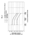
- Fig. 5 is a graph showing a relationship between a cooling air-insertion position and the metal temperature of an impeller while a horizontal axis represents the cooling air-insertion position and a vertical axis represents the metal temperature of the impeller (relative comparison).
- metal temperature at the outermost peripheral portion of the impeller is highest, and metal temperature at an intermediate position (between the outermost peripheral portion and the innermost peripheral portion of the impeller 20) is higher than metal temperature near the center (a portion of the impeller 20 near the rotor shaft 15).
- the insertion of cooling air into a first stage (the cooling holes 5 connecting the outermost peripheral groove 3a to the annular space 7) has the greatest cooling effect, and the cooling effect of the insertion of cooling air into a second stage (the cooling holes 5 positioned on the first inner peripheral side of the outermost peripheral groove 3a from the axis L) is greater than the cooling effect of the insertion of cooling air into a third stage (the cooling holes 5 positioned on the second inner peripheral side of the outermost peripheral groove 3a from the axis L).
- a cooling effect obtained when cooling air is inserted into the cooling hole 5 of the first stage is significantly greater than a cooling effect obtained when cooling air is inserted into the cooling holes 5 of the second and third stages.
- the reason for this is that, when cooling air is inserted from the second and third stages, the temperature of air taken into the back surface of the impeller from the outer peripheral portion of the impeller becomes high due to friction and the amount of heat is increased in comparison with a case in which cooling air is inserted from the first stage.
- annular space 7 in which a cooling medium flows is formed on the back surface of the labyrinth seal 1 and the cooling holes 5 are formed so as to connect the annular space 7 to the outermost peripheral groove 3a, sealing air flows in the annular space 7 in the circumferential direction and becomes uniform. Then, it is possible to supply cooling air to the outermost peripheral groove 3a from the twenty-four cooling holes 5 of the labyrinth seal 1. Accordingly, it is not necessary to reduce the number of the labyrinth grooves 3, and it is possible to lower the metal temperature of the impeller 20, which has risen up to about 230°C, by about 7°C in comparison with a case in which cooling is not performed while ensuring the sealing performance of the labyrinth seal 1.
- the cooling holes 5 have been connected to the outermost peripheral groove 3a of the plurality of labyrinth grooves 3.
- the invention is not limited thereto, and for example, the cooling holes 5 may be connected to the labyrinth groove 3 positioned on the inner peripheral side next to the outermost peripheral groove 3a.
- the number of holes of the labyrinth seal 1 has been 24 in the description of each of the above-mentioned embodiments.
- the invention is not limited thereto, and the number of holes of the labyrinth seal 1 may be determined in consideration of a cooling effect.
- the number of holes of the labyrinth seal 1 may be an even number, such as 12 or 36, or an odd number, such as 21.
- SS400 has been described as the material of the labyrinth seal 1 in the description of each of the above-mentioned embodiments.
- the invention is not limited thereto, and the material of the labyrinth seal 1 may be, for example, steel, such as SS490 or SS540.
- cooling holes 5 have been provided substantially parallel to the axis L in the description.
- the invention is not limited thereto, and the cooling holes 5 only have to connect the labyrinth grooves 3 to the annular space 7.
- the cooling holes 5 may be inclined to the axis L.
- cooling medium air has been used as the cooling medium in each of the above-mentioned embodiments.
- the invention is not limited thereto, and for example, steam may be used as the cooling medium.
Landscapes
- Engineering & Computer Science (AREA)
- Mechanical Engineering (AREA)
- General Engineering & Computer Science (AREA)
- Physics & Mathematics (AREA)
- Thermal Sciences (AREA)
- Structures Of Non-Positive Displacement Pumps (AREA)
- Supercharger (AREA)
Abstract
Description
- The present invention relates to a centrifugal compressor, a supercharger including the centrifugal compressor, and a method of operating a centrifugal compressor, and more particularly, to the cooling of a centrifugal compressor.
- In a centrifugal compressor in the related art, the temperature of air at an outlet of an impeller rises according to a pressure ratio of the centrifugal compressor. For example, even though the centrifugal compressor takes in normal-temperature air, the temperature of air at the outlet of the impeller reaches 200°C or more when a pressure ratio is about 4.5. When this high-temperature air passes through a labyrinth seal sealing between the outlet of the impeller and a space that is formed on the back portion of the impeller, the temperature of the air further rises due to frictional heat that is generated by the rotation of fins of the impeller relative to the labyrinth seal and the back surface of the impeller is heated by the heat. Generally, an aluminum alloy is used as the material of the impeller in a single-stage centrifugal compressor taking in the air. However, since the strength of the aluminum alloy is rapidly reduced as the temperature of an aluminum alloy rises to 250°C or more from 220°C, it is difficult to make a design or an operation that requires a high pressure ratio.
- Further,
PTL 1 discloses a technique in which air passages are formed in an intermediate portion of a labyrinth seal and which prevents the temperature rise of an impeller by the supply of cooling air. - Furthermore, PTL 2 discloses a technique that allows a cooling medium to flow in from the outer peripheral side of an impeller.
-
- [PTL 1] Japanese Patent No.
2934530 - [PTL 2] Japanese Patent No.
4503726 - However, since the outer peripheral side of the impeller where the temperature of the impeller is highest is still spaced apart from the air passages of the intermediate portion to which the cooling air is supplied even in the technique disclosed in
PTL 1, an effect for cooling the outer peripheral side of the impeller is low. Moreover, the air passages, which are separate from the labyrinth grooves, are provided in the intermediate portion of the labyrinth seal, and the width of air passage is increased so that the flow of air is uniform in the circumferential direction. Accordingly, since the wide air passages are present, the number of labyrinth grooves is reduced. For this reason, the deterioration of sealing performance is caused. - Meanwhile, since a cooling medium is not directly guided to the outer peripheral side of the impeller where the temperature of the impeller is highest in the technique disclosed in PTL 2, a cooling effect is low.
- The invention has been made in consideration of the above-mentioned circumstances, and an object of the invention is to provide a centrifugal compressor that can lower metal temperature by cooling an impeller while ensuring the sealing performance of a labyrinth seal, a supercharger including the centrifugal compressor, and a method of operating a centrifugal compressor.
- In order to solve the above-mentioned problems, a centrifugal compressor of the invention, a supercharger including the centrifugal compressor, and a method of operating a centrifugal compressor employ the following means.
- That is, a centrifugal compressor according to a first aspect of the invention includes an impeller that is rotated about an axis, and a labyrinth seal that seals between a wall section positioned on a back side of the impeller and a back surface of the impeller. The labyrinth seal includes labyrinth grooves that are formed of a plurality of circumferential grooves having a center on the axis, and a cooling hole, which allows a cooling medium to flow, is connected to at least one of the plurality of labyrinth grooves.
- According to the first aspect of the invention, the cooling hole for supplying the cooling medium to the impeller is connected to the labyrinth grooves that are formed of the circumferential grooves. Since the labyrinth grooves are utilized as a space for supplying a cooling medium as described above, it is possible to cool the impeller without reducing the number of the labyrinth grooves. Accordingly, the cooling of the impeller and sealing performance, which is obtained from the labyrinth seal, are compatible with each other.
- Further, since the cooling hole is provided in the labyrinth groove and a cooling medium is supplied to the impeller through the cooling hole, the metal temperature of the impeller can be lowered. Accordingly, it is possible to avoid the reduction of the strength of the material of the impeller that is caused by the rise of the temperature of the impeller.
- Furthermore, in a centrifugal compressor according to the second aspect of the invention, an annular space in which the cooling medium flows is provided on a back side of the labyrinth seal and a plurality of the cooling holes are formed so as to connect the annular space to the labyrinth grooves while being spaced apart from each other.
- According to the second aspect of the invention, since the annular space in which the cooling medium flows is provided, the cooling medium can become uniform in the circumferential direction.
- Further, since the annular space, which makes the cooling medium uniform in the circumferential direction, is disposed on the back surface of the labyrinth seal and the cooling hole is provided so as to connect the annular space to the labyrinth grooves, the air passages, which cannot be used as the labyrinth grooves, do not need to be formed unlike in
PTL 1 and the labyrinth grooves can be directly used for cooling. Accordingly, since the number of the labyrinth grooves does not need to be reduced, the sealing performance of the labyrinth seal can be ensured. - Furthermore, since the plurality of cooling holes are formed so as to be spaced apart from each other, it is possible to effectively cool the impeller at each point in the circumferential direction.
- Moreover, in a centrifugal compressor according to a third aspect of the invention, the cooling hole is connected to the labyrinth groove, which is positioned on an outermost peripheral portion, among the plurality of labyrinth grooves having a center on the axis.
- According to the third aspect of the invention, since the cooling hole is connected to the labyrinth groove positioned on the outermost peripheral portion, it is possible to directly send a cooling medium to a portion where metal temperature is highest.
- Further, a method of operating a centrifugal compressor according to a fourth aspect of the invention includes a step of rotating an impeller about an axis by a rotation of an exhaust turbine, and a step of allowing a cooling medium to flow in at least one of labyrinth grooves formed of a plurality of circumferential grooves that are provided on a labyrinth seal positioned on a back side of the impeller and have a center on the axis.
- According to the fourth aspect of the invention, since the cooling medium is made to flow to at least one of the plurality of labyrinth grooves of the labyrinth seal, it is possible to operate the centrifugal compressor at a metal temperature, which is lowered through the cooling of an impeller, while ensuring the sealing performance of the labyrinth seal. Accordingly, it is possible to lengthen the life of the impeller.
- Furthermore, in a method of operating a centrifugal compressor according to a fifth aspect of the invention, the step of allowing the cooling medium to flow supplies the cooling medium to the labyrinth groove, which is positioned on an outermost peripheral portion, among the plurality of labyrinth grooves.
- According to the fifth aspect of the invention, since the cooling hole is connected to the labyrinth groove that is positioned on the outermost peripheral portion, it is possible to directly send the cooling medium to a portion where metal temperature is highest.
- Moreover, a supercharger according to a sixth aspect of the invention includes any one of the centrifugal compressors and an exhaust turbine that drives the centrifugal compressor.
- According to the sixth aspect of the invention, since the supercharger includes any one of the centrifugal compressors, it is possible to obtain a supercharger that can lower metal temperature by cooling the impeller while ensuring the sealing performance of the labyrinth seal.
- According to the invention, since a cooling hole, which allows a cooling medium to flow, is connected to at least one of a plurality of labyrinth grooves of a labyrinth seal, it is possible to lower metal temperature by cooling an impeller while ensuring the sealing performance of the labyrinth seal. Accordingly, it is possible to lengthen the life of the impeller.
-
-
Fig. 1 is a longitudinal cross-sectional view of an exhaust turbine supercharger including a labyrinth seal according to an embodiment of the invention. -
Fig. 2 shows the labyrinth seal ofFig. 1 in whichFig. 2(a) is a longitudinal cross-sectional view of the labyrinth seal andFig. 2(b) is a plan view of the labyrinth seal. -
Fig. 3 is a side cross-sectional view showing a state in which a cooling hole is connected to a labyrinth groove of the labyrinth seal shown inFig. 2 positioned on the radially outermost side having a center on an axis. -
Fig. 4 is a longitudinal cross-sectional view of main parts around the labyrinth seal shown inFig. 1 . -
Fig. 5 is a graph showing a relationship between a cooling air-insertion position and the metal temperature of an impeller while a horizontal axis represents the cooling air-insertion position and a vertical axis represents the impeller metal temperature. - An embodiment of the invention will be described below with reference to the drawings.
- One embodiment of the invention will be described below with reference to
Figs. 1 to 5 . -
Fig. 1 is a longitudinal cross-sectional view of an exhaust turbine supercharger (supercharger) 10 according to this embodiment. Agas inlet casing 11, agas outlet casing 12, abearing stand 13, and a compressor-sideair guide casing 14 are integrally fastened with bolts (not shown), so that theexhaust turbine supercharger 10 is formed. Arotor shaft 15 is rotatably supported in thebearing stand 13 by a thrust bearing 16 andradial bearings rotor shaft 15, and animpeller 20 forming a compressor unit is fixed to the other end portion thereof. - The
turbine 19 includes a plurality ofblades 19a that are provided at an outer peripheral portion thereof. Theblades 19a are disposed between an exhaustgas introduction passage 22 that is provided in thegas inlet casing 11 and an exhaustgas discharge passage 23 that is provided in thegas outlet casing 12. - Meanwhile, the
impeller 20 is disposed in the rear of an intakeair introduction passage 24 that is provided in theair guide casing 14. The intakeair introduction passage 24 is connected to ascroll casing 25 through theimpeller 20, and thescroll casing 25 is connected to a combustion chamber of an engine through an intake air introduction passage (not shown). - Meanwhile, reference numeral 26 denotes a filter that is provided at the front stage of the intake
air introduction passage 24 into which air is taken and rectifies intake air by allowing the intake air to pass therethrough. - Further, a lubricating
oil supply passage 27 is formed in thebearing stand 13, and a base end portion of the lubricatingoil supply passage 27 is connected to an oil pump (not shown) for the engine. Meanwhile, the other end portion of the lubricatingoil supply passage 27 is branched intobranch passages radial bearings - Furthermore, a
labyrinth seal 1, which seals between a wall section positioned on the back side of theimpeller 20 and the back surface of theimpeller 20, is provided at an end portion of the bearing stand 13 close to theimpeller 20. Thelabyrinth seal 1 prevents the leakage of compressed air by sliding on theimpeller 20. - When the
exhaust turbine supercharger 10 having the above-mentioned structure is operated, for example, exhaust gas from a marine diesel engine passes through the exhaustgas introduction passage 22 and theturbine 19 is rotationally driven by an axial exhaust gas flow that has been expanded by a turbine nozzle under static pressure. Further, the exhaust gas having driven theturbine 19 is discharged to the outside through the exhaustgas discharge passage 23. - The rotation of the
turbine 19 rotates theimpeller 20 through aturbine rotor shaft 15, and air taken through the intakeair introduction passage 24 is pressurized by theimpeller 20 and is supplied to the marine diesel engine through adiffuser 33 and anoutlet scroll 35. - Next, the structure of the
labyrinth seal 1 will be described in detail. - As shown in
Fig. 2 , thelabyrinth seal 1 is formed in the shape of a ring that has the axis L as a central axis. For example, SS400 steel is suitably used for thelabyrinth seal 1. - Bolts are inserted into a plurality of outer
peripheral bolt holes 8a and a plurality of innerperipheral bolt holes 8b substantially parallel to the axis L, so that thelabyrinth seal 1 is fixed to a casing body 37 (seeFig. 1 ) (Meanwhile,Fig. 4 shows a state in which thelabyrinth seal 1 is fixed by bolts). The outerperipheral bolt holes 8a and the innerperipheral bolt holes 8b are provided at substantially regular intervals over the entire circumference of thelabyrinth seal 1. - As enlarged in
Fig. 3 , a plurality oflabyrinth grooves 3 are formed on one end face of thelabyrinth seal 1, that is, an end face facing theimpeller 20. Thelabyrinth grooves 3 are a plurality of circumferential grooves that have a center on the axis L. Here, the dimensions (depths and widths) of therespective labyrinth grooves 3 are set to be substantially the same. - As shown in
Fig. 4 , anannular space 7 in which a cooling medium flows is formed on the back surface (the right side inFig. 4 ) of thelabyrinth seal 1. A cooling medium supplied from a main engine is taken into theannular space 7 from the bearing stand 13 that is provided on the side portion of the supercharger. Theannular space 7 is formed in an annular shape having the axis L as a central axis, and is formed so as to be opened toward the back surface of thelabyrinth seal 1. Here, the longitudinal cross-section of theannular space 7 has a substantially rectangular shape inFig. 4 . In addition, the longitudinal dimension of theannular space 7, that is, the length of the annular space in a direction (a vertical direction inFig. 4 ) orthogonal to the axis L, is about a length that covers the plurality of (four in the embodiment shown inFig. 4 )labyrinth grooves 3. Meanwhile, the longitudinal dimension of theannular space 7 is appropriately set according to the amount of air to be required. - The
labyrinth seal 1 is provided withcooling holes 5 formed from an end face (a right end face inFig. 4 ) of the labyrinth seal opposite to an end face (hereinafter, referred to as "a front surface".) thereof, on which thelabyrinth grooves 3 are formed, toward the front surface. The cooling holes 5 extend substantially parallel to the axis L, and connect the outermostperipheral groove 3a to theannular space 7 facing the back surface. Here, the diameter of thecooling hole 5 is smaller than the diameter of the outermostperipheral groove 3a. Meanwhile, since taper machining, which allows the diameter of the cooling hole to increase toward theannular space 7, is performed on the back side of thecooling hole 5 as shown inFig. 3 , thecooling hole 5 is formed in a shape that allows the flow of air flowing from theannular space 7 to be smooth. - As shown in
Fig. 2(b) , the cooling holes 5 are formed at substantially regular intervals, for example, at twenty-four positions over the entire circumference of thelabyrinth seal 1. -
Fig. 5 is a graph showing a relationship between a cooling air-insertion position and the metal temperature of an impeller while a horizontal axis represents the cooling air-insertion position and a vertical axis represents the metal temperature of the impeller (relative comparison). As shown inFig. 5 , metal temperature at the outermost peripheral portion of the impeller is highest, and metal temperature at an intermediate position (between the outermost peripheral portion and the innermost peripheral portion of the impeller 20) is higher than metal temperature near the center (a portion of theimpeller 20 near the rotor shaft 15). - Further, the insertion of cooling air into a first stage (the cooling holes 5 connecting the outermost
peripheral groove 3a to the annular space 7) has the greatest cooling effect, and the cooling effect of the insertion of cooling air into a second stage (the cooling holes 5 positioned on the first inner peripheral side of the outermostperipheral groove 3a from the axis L) is greater than the cooling effect of the insertion of cooling air into a third stage (the cooling holes 5 positioned on the second inner peripheral side of the outermostperipheral groove 3a from the axis L). - Furthermore, it is found that a cooling effect obtained when cooling air is inserted into the
cooling hole 5 of the first stage is significantly greater than a cooling effect obtained when cooling air is inserted into the cooling holes 5 of the second and third stages. The reason for this is that, when cooling air is inserted from the second and third stages, the temperature of air taken into the back surface of the impeller from the outer peripheral portion of the impeller becomes high due to friction and the amount of heat is increased in comparison with a case in which cooling air is inserted from the first stage. - According to this embodiment, the following effects are obtained from the above-mentioned structure.
- Since the
annular space 7 in which a cooling medium flows is formed on the back surface of thelabyrinth seal 1 and the cooling holes 5 are formed so as to connect theannular space 7 to the outermostperipheral groove 3a, sealing air flows in theannular space 7 in the circumferential direction and becomes uniform. Then, it is possible to supply cooling air to the outermostperipheral groove 3a from the twenty-fourcooling holes 5 of thelabyrinth seal 1. Accordingly, it is not necessary to reduce the number of thelabyrinth grooves 3, and it is possible to lower the metal temperature of theimpeller 20, which has risen up to about 230°C, by about 7°C in comparison with a case in which cooling is not performed while ensuring the sealing performance of thelabyrinth seal 1. - Meanwhile, in the description of the above-mentioned embodiment, the cooling holes 5 have been connected to the outermost
peripheral groove 3a of the plurality oflabyrinth grooves 3. However, the invention is not limited thereto, and for example, the cooling holes 5 may be connected to thelabyrinth groove 3 positioned on the inner peripheral side next to the outermostperipheral groove 3a. Further, the number of holes of thelabyrinth seal 1 has been 24 in the description of each of the above-mentioned embodiments. However, the invention is not limited thereto, and the number of holes of thelabyrinth seal 1 may be determined in consideration of a cooling effect. For example, the number of holes of thelabyrinth seal 1 may be an even number, such as 12 or 36, or an odd number, such as 21. - Furthermore, SS400 has been described as the material of the
labyrinth seal 1 in the description of each of the above-mentioned embodiments. However, the invention is not limited thereto, and the material of thelabyrinth seal 1 may be, for example, steel, such as SS490 or SS540. - Moreover, the cooling holes 5 have been provided substantially parallel to the axis L in the description. However, the invention is not limited thereto, and the cooling holes 5 only have to connect the
labyrinth grooves 3 to theannular space 7. For example, the cooling holes 5 may be inclined to the axis L. - Further, air has been used as the cooling medium in each of the above-mentioned embodiments. However, the invention is not limited thereto, and for example, steam may be used as the cooling medium.
-
- 1:
- labyrinth seal
- 3:
- labyrinth groove
- 3a:
- outermost peripheral groove (a labyrinth groove positioned on the radially outermost side having a center on an axis)
- 5:
- cooling hole
- 7:
- annular space
- 8a:
- outer peripheral bolt hole
- 8b:
- inner peripheral bolt hole
- 10:
- exhaust turbine supercharger
- 11:
- gas inlet casing
- 12:
- gas outlet casing
- 13:
- bearing stand
- 14:
- compressor-side air guide casing
- 15:
- rotor shaft
- 16:
- thrust bearing
- 17, 18:
- radial bearing
- 19:
- turbine
- 19a:
- blade
- 20:
- impeller
- 22:
- exhaust gas introduction passage
- 23:
- exhaust gas discharge passage
- 24:
- intake air introduction passage
- 25:
- scroll casing
- 26:
- filter
- 27:
- lubricating oil supply passage
- 28, 29, 30:
- branch passage
- 31:
- compressor housing
- 33:
- diffuser
- 35:
- outlet scroll
- 37:
- casing body
- L:
- axis
Claims (6)
- A centrifugal compressor comprising:an impeller that is rotated about an axis; anda labyrinth seal that seals between a wall section positioned on a back side of the impeller and a back surface of the impeller,wherein the labyrinth seal includes labyrinth grooves that are formed of a plurality of circumferential grooves having a center on the axis, anda cooling hole, which allows a cooling medium to flow, is connected to at least one of the plurality of labyrinth grooves.
- The centrifugal compressor according to claim 1, wherein an annular space in which the cooling medium flows is provided on a back side of the labyrinth seal, and
a plurality of the cooling holes are formed so as to connect the annular space to the labyrinth grooves while being spaced apart from each other. - The centrifugal compressor according to claim 1 or 2,
wherein the cooling hole is connected to the labyrinth groove, which is positioned on an outermost peripheral portion, among the plurality of labyrinth grooves having a center on the axis. - A supercharger comprising:the centrifugal compressor according to any one of claims 1 to 3; andan exhaust turbine that drives the centrifugal compressor.
- A method of operating a centrifugal compressor, the method comprising:a step of rotating an impeller about an axis by a rotation of an exhaust turbine; anda step of allowing a cooling medium to flow in at least one of labyrinth grooves formed of a plurality of circumferential grooves that are provided on a labyrinth seal positioned on a back side of the impeller and have a center on the axis.
- The method of operating a centrifugal compressor according to claim 5,
wherein the step of allowing the cooling medium to flow supplies the cooling medium to the labyrinth groove, which is positioned on an outermost peripheral portion, among the plurality of labyrinth grooves.
Applications Claiming Priority (2)
| Application Number | Priority Date | Filing Date | Title |
|---|---|---|---|
| JP2012266274A JP2014111905A (en) | 2012-12-05 | 2012-12-05 | Centrifugal compressor and supercharger with the same, and operation method for centrifugal compressor |
| PCT/JP2013/082346 WO2014087966A1 (en) | 2012-12-05 | 2013-12-02 | Centrifugal compressor, supercharger with same, and method for operating centrifugal compressor |
Publications (2)
| Publication Number | Publication Date |
|---|---|
| EP2930370A1 true EP2930370A1 (en) | 2015-10-14 |
| EP2930370A4 EP2930370A4 (en) | 2015-12-02 |
Family
ID=50883383
Family Applications (1)
| Application Number | Title | Priority Date | Filing Date |
|---|---|---|---|
| EP13861290.8A Withdrawn EP2930370A4 (en) | 2012-12-05 | 2013-12-02 | Centrifugal compressor, supercharger with same, and method for operating centrifugal compressor |
Country Status (5)
| Country | Link |
|---|---|
| EP (1) | EP2930370A4 (en) |
| JP (1) | JP2014111905A (en) |
| KR (1) | KR20150081342A (en) |
| CN (1) | CN104903586A (en) |
| WO (1) | WO2014087966A1 (en) |
Cited By (1)
| Publication number | Priority date | Publication date | Assignee | Title |
|---|---|---|---|---|
| US11199201B2 (en) | 2016-02-22 | 2021-12-14 | Mitsubishi Heavy Industries Marine Machinery & Equipment Co., Ltd. | Impeller back surface cooling structure and supercharger |
Families Citing this family (7)
| Publication number | Priority date | Publication date | Assignee | Title |
|---|---|---|---|---|
| JP6404087B2 (en) * | 2014-11-05 | 2018-10-10 | 三菱重工業株式会社 | Centrifugal compressor and supercharger provided with the same |
| DE102014226951A1 (en) | 2014-12-23 | 2016-06-23 | Robert Bosch Gmbh | turbomachinery |
| JP6147777B2 (en) * | 2015-01-26 | 2017-06-14 | 三菱重工業株式会社 | Intake rectifier, compressor provided with the same |
| JP6382120B2 (en) * | 2015-01-26 | 2018-08-29 | 三菱重工業株式会社 | Exhaust turbine turbocharger |
| CN110671157A (en) * | 2019-11-22 | 2020-01-10 | 东方电气集团东方汽轮机有限公司 | Radial steam seal structure for radial turbine and radial turbine |
| JP7105823B2 (en) * | 2020-02-28 | 2022-07-25 | 三菱重工マリンマシナリ株式会社 | supercharger |
| WO2022208839A1 (en) | 2021-04-01 | 2022-10-06 | 三菱重工マリンマシナリ株式会社 | Supercharger |
Family Cites Families (5)
| Publication number | Priority date | Publication date | Assignee | Title |
|---|---|---|---|---|
| JP2934530B2 (en) | 1991-06-14 | 1999-08-16 | 三菱重工業株式会社 | Centrifugal compressor |
| EP0961034B1 (en) | 1998-05-25 | 2003-09-03 | ABB Turbo Systems AG | Radial compressor |
| JP2008045425A (en) * | 2006-08-11 | 2008-02-28 | Mitsubishi Heavy Ind Ltd | Centrifugal compressor |
| DE102006048784A1 (en) * | 2006-10-12 | 2008-04-17 | Man Diesel Se | Compressor for a turbocharger and method for its cooling |
| EP2067999A1 (en) * | 2007-12-06 | 2009-06-10 | Napier Turbochargers Limited | Liquid cooled turbocharger impeller and method for cooling an impeller |
-
2012
- 2012-12-05 JP JP2012266274A patent/JP2014111905A/en active Pending
-
2013
- 2013-12-02 CN CN201380063139.4A patent/CN104903586A/en active Pending
- 2013-12-02 WO PCT/JP2013/082346 patent/WO2014087966A1/en not_active Ceased
- 2013-12-02 KR KR1020157014736A patent/KR20150081342A/en not_active Withdrawn
- 2013-12-02 EP EP13861290.8A patent/EP2930370A4/en not_active Withdrawn
Cited By (1)
| Publication number | Priority date | Publication date | Assignee | Title |
|---|---|---|---|---|
| US11199201B2 (en) | 2016-02-22 | 2021-12-14 | Mitsubishi Heavy Industries Marine Machinery & Equipment Co., Ltd. | Impeller back surface cooling structure and supercharger |
Also Published As
| Publication number | Publication date |
|---|---|
| JP2014111905A (en) | 2014-06-19 |
| EP2930370A4 (en) | 2015-12-02 |
| KR20150081342A (en) | 2015-07-13 |
| CN104903586A (en) | 2015-09-09 |
| WO2014087966A1 (en) | 2014-06-12 |
Similar Documents
| Publication | Publication Date | Title |
|---|---|---|
| EP2090788A1 (en) | Impeller and turbocharger | |
| KR20150081342A (en) | Centrifugal compressor, supercharger with same, and method for operating centrifugal compressor | |
| US9567864B2 (en) | Centrifugal impeller and turbomachine | |
| CN107849973B (en) | Impeller back surface cooling structure and supercharger | |
| US7682131B2 (en) | Impeller baffle with air cavity deswirlers | |
| EP2243933A1 (en) | Part of a casing, especially of a turbo machine | |
| CN104520592B (en) | Centrufugal compressor impeller cools down | |
| CN104583558B (en) | Turbocharger with compressor cooling and method | |
| CN107304685A (en) | Gas bearing seal | |
| EP1926915B1 (en) | Stationary seal ring for a centrifugal compressor | |
| JP2021089072A (en) | Journal and thrust gas bearing | |
| US20070065277A1 (en) | Centrifugal compressor including a seal system | |
| EP3434875A1 (en) | Turbocharger | |
| CN102207093A (en) | Compressor | |
| CA2992684C (en) | Turbine housing assembly | |
| CN110344927B (en) | internal combustion engine | |
| KR102780126B1 (en) | supercharger | |
| US11761339B2 (en) | Turbine blade | |
| US20170321565A1 (en) | Ingestion seal | |
| EP3426894B1 (en) | Turbine last stage rotor blade with forced driven cooling air | |
| JP2025542133A (en) | Seal flow circuits in the outlet region of a turbomachine compressor | |
| JP2007321654A (en) | Supercharger |
Legal Events
| Date | Code | Title | Description |
|---|---|---|---|
| PUAI | Public reference made under article 153(3) epc to a published international application that has entered the european phase |
Free format text: ORIGINAL CODE: 0009012 |
|
| 17P | Request for examination filed |
Effective date: 20150601 |
|
| AK | Designated contracting states |
Kind code of ref document: A1 Designated state(s): AL AT BE BG CH CY CZ DE DK EE ES FI FR GB GR HR HU IE IS IT LI LT LU LV MC MK MT NL NO PL PT RO RS SE SI SK SM TR |
|
| AX | Request for extension of the european patent |
Extension state: BA ME |
|
| RA4 | Supplementary search report drawn up and despatched (corrected) |
Effective date: 20151029 |
|
| RIC1 | Information provided on ipc code assigned before grant |
Ipc: F04D 29/08 20060101AFI20151023BHEP Ipc: F04D 29/58 20060101ALI20151023BHEP |
|
| DAX | Request for extension of the european patent (deleted) | ||
| STAA | Information on the status of an ep patent application or granted ep patent |
Free format text: STATUS: THE APPLICATION IS DEEMED TO BE WITHDRAWN |
|
| 18D | Application deemed to be withdrawn |
Effective date: 20160528 |