EP2930367A1 - Pump blade for submerged pump and submerged pump having same - Google Patents
Pump blade for submerged pump and submerged pump having same Download PDFInfo
- Publication number
- EP2930367A1 EP2930367A1 EP14819908.6A EP14819908A EP2930367A1 EP 2930367 A1 EP2930367 A1 EP 2930367A1 EP 14819908 A EP14819908 A EP 14819908A EP 2930367 A1 EP2930367 A1 EP 2930367A1
- Authority
- EP
- European Patent Office
- Prior art keywords
- pump impeller
- pump
- flow channels
- flow channel
- intake port
- Prior art date
- Legal status (The legal status is an assumption and is not a legal conclusion. Google has not performed a legal analysis and makes no representation as to the accuracy of the status listed.)
- Granted
Links
- 239000012530 fluid Substances 0.000 claims abstract description 15
- 230000003746 surface roughness Effects 0.000 claims description 6
- 239000010865 sewage Substances 0.000 description 42
- 230000007423 decrease Effects 0.000 description 6
- 238000000926 separation method Methods 0.000 description 4
- XLYOFNOQVPJJNP-UHFFFAOYSA-N water Substances O XLYOFNOQVPJJNP-UHFFFAOYSA-N 0.000 description 3
- 230000000694 effects Effects 0.000 description 2
- 230000010349 pulsation Effects 0.000 description 2
- 238000011144 upstream manufacturing Methods 0.000 description 2
- 230000003466 anti-cipated effect Effects 0.000 description 1
- 238000005266 casting Methods 0.000 description 1
- 230000007797 corrosion Effects 0.000 description 1
- 238000005260 corrosion Methods 0.000 description 1
- 238000006073 displacement reaction Methods 0.000 description 1
- 239000013505 freshwater Substances 0.000 description 1
- 230000005484 gravity Effects 0.000 description 1
- 239000011796 hollow space material Substances 0.000 description 1
- 239000002184 metal Substances 0.000 description 1
- 239000007769 metal material Substances 0.000 description 1
- 229910052755 nonmetal Inorganic materials 0.000 description 1
- 239000007787 solid Substances 0.000 description 1
Images


Classifications
-
- F—MECHANICAL ENGINEERING; LIGHTING; HEATING; WEAPONS; BLASTING
- F04—POSITIVE - DISPLACEMENT MACHINES FOR LIQUIDS; PUMPS FOR LIQUIDS OR ELASTIC FLUIDS
- F04D—NON-POSITIVE-DISPLACEMENT PUMPS
- F04D29/00—Details, component parts, or accessories
- F04D29/18—Rotors
- F04D29/22—Rotors specially for centrifugal pumps
- F04D29/2238—Special flow patterns
- F04D29/225—Channel wheels, e.g. one blade or one flow channel
-
- F—MECHANICAL ENGINEERING; LIGHTING; HEATING; WEAPONS; BLASTING
- F04—POSITIVE - DISPLACEMENT MACHINES FOR LIQUIDS; PUMPS FOR LIQUIDS OR ELASTIC FLUIDS
- F04D—NON-POSITIVE-DISPLACEMENT PUMPS
- F04D13/00—Pumping installations or systems
- F04D13/02—Units comprising pumps and their driving means
-
- F—MECHANICAL ENGINEERING; LIGHTING; HEATING; WEAPONS; BLASTING
- F04—POSITIVE - DISPLACEMENT MACHINES FOR LIQUIDS; PUMPS FOR LIQUIDS OR ELASTIC FLUIDS
- F04D—NON-POSITIVE-DISPLACEMENT PUMPS
- F04D29/00—Details, component parts, or accessories
- F04D29/18—Rotors
- F04D29/22—Rotors specially for centrifugal pumps
- F04D29/2238—Special flow patterns
- F04D29/2255—Special flow patterns flow-channels with a special cross-section contour, e.g. ejecting, throttling or diffusing effect
-
- F—MECHANICAL ENGINEERING; LIGHTING; HEATING; WEAPONS; BLASTING
- F04—POSITIVE - DISPLACEMENT MACHINES FOR LIQUIDS; PUMPS FOR LIQUIDS OR ELASTIC FLUIDS
- F04D—NON-POSITIVE-DISPLACEMENT PUMPS
- F04D29/00—Details, component parts, or accessories
- F04D29/40—Casings; Connections of working fluid
- F04D29/42—Casings; Connections of working fluid for radial or helico-centrifugal pumps
- F04D29/426—Casings; Connections of working fluid for radial or helico-centrifugal pumps especially adapted for liquid pumps
-
- F—MECHANICAL ENGINEERING; LIGHTING; HEATING; WEAPONS; BLASTING
- F04—POSITIVE - DISPLACEMENT MACHINES FOR LIQUIDS; PUMPS FOR LIQUIDS OR ELASTIC FLUIDS
- F04D—NON-POSITIVE-DISPLACEMENT PUMPS
- F04D29/00—Details, component parts, or accessories
- F04D29/66—Combating cavitation, whirls, noise, vibration or the like; Balancing
- F04D29/669—Combating cavitation, whirls, noise, vibration or the like; Balancing especially adapted for liquid pumps
-
- F—MECHANICAL ENGINEERING; LIGHTING; HEATING; WEAPONS; BLASTING
- F04—POSITIVE - DISPLACEMENT MACHINES FOR LIQUIDS; PUMPS FOR LIQUIDS OR ELASTIC FLUIDS
- F04D—NON-POSITIVE-DISPLACEMENT PUMPS
- F04D7/00—Pumps adapted for handling specific fluids, e.g. by selection of specific materials for pumps or pump parts
- F04D7/02—Pumps adapted for handling specific fluids, e.g. by selection of specific materials for pumps or pump parts of centrifugal type
- F04D7/04—Pumps adapted for handling specific fluids, e.g. by selection of specific materials for pumps or pump parts of centrifugal type the fluids being viscous or non-homogenous
Definitions
- the present invention relates to a pump impeller for a submerged pump, and in particular to a pump impeller for a submerged pump for sewage and a submerged pump provided with the impeller.
- a pump impeller 111 as illustrated in Figure 9 is used within the submerged pump (see Patent Literature 1).
- the pump impeller 111 is generally in a cylindrical shape, which includes an intake port 129 formed at one end and a discharge port 134 formed laterally on the side of the other end, and a spiral flow channel 135 partitioned and formed therein, connecting the intake port 129 with the discharge port 134.
- the pump impeller 111 further includes a flange portion 140 that protrudes outward along the circumferential surface of the pump impeller 111 from a portion closer to the intake port than the discharge port 134 on the circumferential surface and separates the intake port side from the discharge port side.
- the pump impeller 111 is contained in a pump casing 112 and connected to a closed-type submerged motor 113 for rotatably driving the pump impeller 111.
- the submerged motor 113 includes a motor 116 having a stator 114 and a rotor 115 and a motor casing 117 that covers the motor 116.
- a driving shaft 118 extending vertically is provided at the center portion of the rotor 115.
- the driving shaft 118 is rotatably supported by bearings 119 and 120 at the upper end portion and an intermediate portion on the lower side, respectively.
- the pump impeller 111 is then connected to the lower end portion of the driving shaft 118.
- a pump chamber 126 which is partitioned by an inner wall 125 that is recessed in a semicircular shape in its cross section, is formed within the pump casing 112.
- a discharge portion 138 of the pump impeller 111 is contained in the pump chamber 126.
- An intake portion 121 that protrudes downward is formed in the lower portion of the pump casing 112.
- An intake port 122 that is open downward is formed in the intake portion 121.
- a discharge portion 123 that protrudes laterally is formed on the side portion of the pump casing 112.
- the discharge portion 123 includes a discharge port 124 formed therein, which is open laterally.
- the pump impeller 111 is provided with an intake portion 127 and a discharge portion 128 axially from the lower side toward the upper side in this order.
- the intake portion 127 and the discharge portion 128 are both formed generally in a cylindrical shape, and the discharge portion 128 is constructed to have a diameter larger than the intake portion 127.
- the discharge portion 128 is separated from the intake portion 127 by the flange portion 140 that protrudes outward from the circumferential surface of the pump impeller 11.
- An intake port 129 that is open downward is formed at the lower end of the intake portion 127 of the pump impeller 111.
- the upper side of the discharge portion 128 is covered by an upper end wall. In other words, the upper side of the pump impeller 111 is hermetically closed by the upper end wall.
- a hole is provided at the center portion of the upper end wall for inserting a distal end of the driving shaft 118, and a periphery of the hole constitutes a mounting portion 131 for mounting the driving shaft 118.
- the reference numeral 137 denotes a secondary flow channel and the reference numeral 138 denotes a secondary blade.
- Patent Literature 1 Japanese Patent No. 4713066
- the pump impeller 111 is adapted to take in sewage from the intake port 129 that is open downward in coaxial with the driving shaft 118, and the sewage is drained from the discharge port 134 through the one spiral flow channel.
- the area where the spiral flow channel is formed is weightless because it is hollow space.
- the area forming the wall of the pump impeller 111 has weight. For this reason, the weight of the pump impeller 111 is significantly eccentrically distributed in the circumference direction with respect to the axis (center of rotation) of the driving shaft 118. When such pump impeller 111 rotates, the deviation of the weight of fluid also increases with respect to the center of rotation, which is likely to cause a radial load.
- the above-mentioned "dynamic balance” is defined herein as displacement of the center of gravity and the center of moment with respect to the axis of rotation when an impeller is rotated in the atmosphere.
- the dynamic balance can be removed by a correction such as thinning of the wall as described above.
- the fluid balance refers to balance in the case where a fluid is flowing in a channel while a pump impeller is rotating. Even if the dynamic balance is optimized (zero weight unbalance), the area of water (sewage) in the pump impeller is eccentric with respect to the axis of rotation when the pump impeller is rotated under water. This causes fluid unbalance and a force (which is referred to as a radial load) is applied to the pump impeller via the wall pressure.
- a large radial load may cause vibration, and thus efforts have been made to cancel the load, such as by applying a weight.
- a multi-channel pump impeller such as that in the present invention can significantly reduce the radial load because the mass distribution of the water area is less likely to be nonaxisymmetric as compared to a single-channel pump impeller.
- the present invention which has been made in view of the above problem, provides in a first aspect a pump impeller for a non-clogging submerged pump including a generally cylindrical body, an intake port provided in a center of a lower end surface of the body, a discharge port that is open in a side surface of the body, and a flow channel passing from the intake port to the discharge port within the body.
- the flow channel includes a plurality of flow channels, and the flow channels have their size, shape, and position defined such that fluid unbalance is reduced with respect to an axis of rotation.
- sewage taken in from the intake port is divided and flows into each of the flow channels.
- fluid unbalance is less likely to occur with respect to the axis of rotation because the flow channels are designed to reduce the fluid unbalance, and thus the occurrence of radial load associated with rotation of the pump impeller can significantly be suppressed.
- the flow channel includes two or more flow channels. According to the configuration, sewage is drained more than once per revolution of the pump impeller, and thus pressure variation during drainage can be suppressed.
- a cross-sectional area of the flow channel varies between the intake port and the discharge port.
- sewage when sewage separates from a surface of the flow channel near the discharge port, sewage may be prevented from being taken in from the intake port. Accordingly, the varying cross-sectional area is provided in some positions in order to maintain the pressure above a predetermined level.
- a cross-sectional shape of the flow channel varies between the intake port and the discharge port. Furthermore, in a fifth aspect, the cross-sectional shape of the flow channel changes from circular to generally rectangular or elliptic from the intake port toward the discharge port.
- the intake port is circular and an upstream portion of the flow channel is also circular; while the circumferential surface of the pump impeller has a shape similar to that of a circumferential surface of a cylinder. Accordingly, the cross-sectional shape needs to be changed near the discharge port in order to secure a constant cross-sectional area.
- an inner wall surface of the flow channel is formed of a continuous curved surface. According to the configuration, foreign matters in sewage flow smoothly in the flow channel so that the occurrence of clogging or the like due to the foreign matters can be prevented.
- inner walls close to a junction of at least two of the flow channels have a surface roughness different from each other.
- elongated fibrous foreign matters may be divided and flow into two flow channels at a junction close to the intake port.
- the frictional resistance is lower on the side of a flow channel having a smoother surface, so that the foreign matters are likely to flow in the side of the flow channel.
- all of the flow channels have the same size and shape, and are disposed at an equal angular interval with respect to the axis of rotation. According to the configuration, sewage taken in from the intake port is divided and flows into each of the flow channels. At this time, since the flow channels have the same size and shape, and are disposed in positions located at an equal angular interval with respect to the axis of rotation, no weight unbalance with respect to the axis of rotation occurs, and thus the occurrence of radial load associated with rotation of the pump impeller can be minimized.
- a submerged pump is characterized by including a pump impeller according to any one of the first to eighth aspects, a pump casing that contains the pump impeller; and a motor that drives the pump impeller. According to the configuration, a pump having a good fluid balance can be realized when assembled and operated as a pump, without problems such as noise and vibration.
- a pump impeller according to an embodiment of the preset invention will now be described with reference to Figures 1 to 8 .
- the pump impeller of the embodiment includes a plurality of flow channels that bring an intake port coaxial with an axis of rotation into communication with a discharge port on an outer circumferential portion and the flow channels are disposed at an equal angular interval with respect to the axis of rotation by logical add.
- the number of flow channels are not limited, Figures 3(A) to 5(B) illustrate an embodiment with two flow channels, and Figures 6(A) to 8(B) illustrate an embodiment with three flow channels.
- the flow channels are bent in a curved shape between the intake port and the discharge port.
- the pump impeller is produced by casting. However, as long as strength or corrosion resistance can be secured, any other metal or non-metal material may be used.
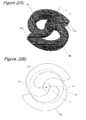
- Figure 1(A) is an image by computer graphics, illustrating a flow channel 3 used in a pump impeller.
- the flow channel is coaxial with the axis of rotation C near the intake port 5.
- the central axis of the flow channel 3 near the intake port 5 is parallel to and coincident with the axis of rotation C.
- the central axis of the flow channel 3 extends downward and then radially outward with respect to the axis of rotation C.
- a transitional portion from the direction of the axis of rotation to the radially outward direction is formed of a continuous curve.
- the central axis of the flow channel 3 extends radially outward, it further extends circumferentially with respect to the axis of rotation C. Accordingly, as a result of a combination of the radially outward component with the circumferential component, the central axis of the flow channel 3 extends outward in a spiral manner.
- the cross-sectional shape of the flow channel 3 is a complete circle near the intake port 5, while it is rectangular near the discharge port 7. Accordingly, a transitional region from the intake port 5 toward the discharge port 7 continuously changes such that a circle gradually turns into a rectangle. Note that even though the term rectangle is used, corner portions do not have right-angled surfaces but are formed of curves of a small radius of curvature. This arrangement is for preventing foreign matters from being accumulated in the corner portions.
- Figure 1(A) illustrates a logical shape of the flow channel 3; when applied to an actual pump impeller, an outer edge of the pump impeller is circular about the axis of rotation C. Specifically, an ellipse illustrated in Figure 1(A) defines the outer edge of the pump impeller. Accordingly, an actual flow channel 3 formed in the pump impeller has a shape as illustrated in Figure 1(B) in which the discharge port 7 is formed over a broad angular range.
- the shape of the flow channel 3 used in a pump impeller has been described. This description, however, is of a case in which only one flow channel 3 is provided. As described below, the embodiment is characterized by a combination of two flow channels, and thus a specific example thereof will be described.
- Figure 2(A) illustrates a configuration that includes two flow channels 13A and 13B and that has been subjected to logical add with reference to the axis of rotation C (intake port).
- the flow channels 13A and 13B have completely the same size and shape as each other and are located at point-symmetric positions with respect to the central axis C.
- the flow channel 3 in Figures 1(A) and 1(B) is rotationally copied and disposed at an equal angular interval.
- regions where the flow channels 13A and 13B are directed radially outward from an intake port 15 extend in directions mutually spaced by 180° (opposite directions).
- the logical add used herein refers to simply combining two flow channels with a common intake port.
- FIG 2(B) illustrates actual flow channels 13A and 13B by the outer edge of the pump impeller (illustrated by a dotted line), similarly to Figure 1(B) .
- the flow channels 13A and 13B are completely point-symmetric with respect to the axis of rotation C, and form a generally S-shaped flow channel as a whole.
- discharge ports 17A and 17B are formed over a broad angular range, similarly to the example in Figure 1(B) .
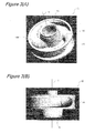
- Figures 3 are views of a pump impeller 11 according to the embodiment created by computer graphics.
- Figure 3(A) is a view seen obliquely from the intake port 15 side
- Figure 3(B) is a view seen from the side.
- Flow channels formed inside the pump impeller 11 illustrated in the figure are the flow channels 13A and 13B illustrated in Figure 2(B) .
- the cross-sectional shape of a flow channel is nearly circular on the right side (upstream side) of the axis of rotation C, while it is in a shape forming a part of a rectangle on the left side (downstream side) of the axis of rotation.
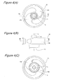
- Figures 4(A), 4(B) and 4(C) illustrate the pump impeller 11 of the embodiment, and are a plan view, a side view, and a bottom view, respectively.
- a cylindrical hub 14 is formed in a region of the central axis C, and the hub 14 is adapted to receive an inserted driving shaft (not illustrated) of a driving motor.
- the pump impeller 11 is adapted to rotate at the number of revolution on the order of 1500 rpm. However, if efficiency can be improved, the pump impeller may be rotated at any number of revolution that is lower or higher than 1500 rpm.
- FIG. 5(A) is a sectional view taken along the line 5A-5A in Figure 4(B) .
- the pump impeller 11 includes an intake port 15 formed therein that is open to one side of the central axis C, and sewage is taken in as the pump impeller 11 rotates. The sewage is then transported from the intake port 15 circumferentially outward along the flow channels 13A and 13B, finally drained from the discharge ports 17A and 17B.
- a driving shaft is inserted in the opening as described above, and thus the sewage will not leak from the opening.
- FIG. 5(B) is a sectional view taken along the line 5B-5B in Figure 4(B) .
- the flow channels 13A and 13B continuing from the intake port 15 extend radially outward in a spiral manner, and provide discharge ports 17A and 17B on the outer edge of the pump impeller 11. Accordingly, other portions than the flow channels are wall portions constituting the pump impeller 11.
- the discharge ports 17A and 17B of the embodiment are formed in an angular range of approximately 180° with respect to the central axis C. This is based on a basic idea that there are two flow channels 13A and 13B and that efficiency is improved by forming discharge ports 17A and 17B over as broad angular range as possible.
- a pump casing 16 is also illustrated for convenience in explanation. Description will be made later as to how the pump impeller 11 and the pump casing 16 are related.
- the intake port 15 is cylindrical and is open so as to be coaxial with the axis of rotation C. Accordingly, the intake port 15 is formed as substantially common one port by logical add.
- the intake port 15 is disposed so as to be open downward when it is actually installed in a pump.
- the inner diameter of the intake port 15 is set based on the volume of solid matters contained in sewage handled by the pump impeller 11.
- the flow channels 13A and 13B branch out from one intake port 15 into two flow channels, as described above.
- the flow channels 13A and 13B have approximately the same cross-sectional area from near the intake port 15 up to the junction.
- the cross-sectional area is gradually reduced from the junction toward the downstream. This is because if the cross-sectional area of each of the flow channels 13A and 13B is equivalent to the cross-sectional area of the intake port 15 after branching, the sum of the areas doubles and the pressure of sewage decreases, which may cause a separation phenomenon of sewage from an inner surface of the flow channels 13A and 13B.
- the rate of decrease in the cross-sectional area of the flow channels 13A and 13B after branching varies depending on the nature of sewage handled or parameters such as the number of revolution of the pump impeller 11. For example, when the viscosity of sewage is high, the separation phenomenon is less likely to occur so that the rate of decrease in the cross-sectional area may be small. When the number of revolution of the pump impeller 11 is high, then the separation phenomenon is likely to occur so that the rate of decrease in the cross-sectional area may desirably be increased.
- the cross-sectional area of the flow channels 13A and 13B after branching is approximately 0.55 (in the case of two flow channels) per unit of the cross-sectional area of the intake port 15.
- the inner wall surfaces of the flow channels 13A and 13B near the junction is formed to have a surface roughness different from each other. This is to address the case in which fibrous objects (elongated string-like objects) are preset in sewage. For example, assume that a fibrous object on the order of several tens of centimeters long is preset in sewage. In this case, opposite ends of the fibrous object may possibly flow in two flow channels 13A and 13B separately. If such a case happens, the fibrous object sticks to and remains in the junction.
- fibrous objects elongated string-like objects
- the fibrous object is allowed to flow in one of the flow channels 13A and 13B smoothly.
- the inner surface of one flow channel 13A is smoothened, and the inner surface of the other flow channel 13B is formed in a roughened state (for example, as-cast state).
- the frictional resistance on the fibrous object is lower on the smooth inner surface, and to the contrary, the coefficient of friction is higher on the rough inner surface.
- Such imbalance in the coefficient of friction allows the fibrous object to flow in the side of the flow channel having the smooth inner surface. In this way, a possible problem that may be associated with two flow channels 13A and 13B can be solved by intentionally altering the surface roughness.
- the flow channels 13A and 13B are subjected to a pressure drop.
- sewage is taken in from the intake port 15.
- the cross-sectional area of the flow channels 13A and 13B is defined to prevent sewage from separating from the inner surface of the flow channels 13A and 13B near the discharge ports 17A and 17B, as described above.
- the cross-sectional area of the flow channels 13A and 13B may be gradually changed from the intake port 15 toward the discharge ports 17A and 17B, or may be constant in a predetermined section and constant at a different scale in other sections.
- the flow channels 13A and 13B of the embodiment have a cross-sectional shape that changes from circular to rectangular between the intake port 15 and the discharge ports 17A and 17B.
- these cross-sectional shapes are only exemplary. Sequentially from the intake port 15 to discharge ports 17A and 17B, any combination may be made, for example: circular -> a transitional region -> elliptic, or circular -> a transitional region -> elliptic -> a transitional region -> rectangular.
- rectangular in the embodiment refers to a square, an oblong cross-sectional shape may be used.
- All inner wall surfaces of the flow channels 13A and 13B are formed of a continuous curved surface. This is to prevent the flow channels 13A and 13B from being clogged with foreign matters.
- the cross-sectional shape of the flow channels 13A and 13B is rectangular near the discharge ports 17A and 17B. Corner portions of the cross-section are not completely right-angled but are connected by a continuous curved surface. Furthermore, a longitudinal axis (a line connecting sectional centers from the intake port 15 to the discharge ports 17A and 17B) of the flow channels 13A and 13B is also continuous. In this way, foreign matters are prevented from being caught in the flow channels 13A and 13B while sewage is flowing.
- Figures 6(A), 6(B) and 7 are views for describing a pump impeller 21 with three flow channels according to a second embodiment.
- Figure 6(A) corresponds to Figure 2(A) of the first embodiment
- Figure 6(B) corresponds to Figure 2(B)
- Figure 7 corresponds to Figure 5 .
- Figures 6(A) and 6(B) illustrate three flow channels 23A, 23B and 23C disposed in positions located at an equal angular interval around an intake port 25.
- the flow channels 23A, 23B and 23C have completely the same size and shape as each other and formed by rotationally copying the flow channel in Figures 1(A) and 1(B) and disposing them at an equal angular interval with respect to the central axis C. Accordingly, as illustrated in Figure 6(B) , regions where the flow channels 23A, 23B and 23C are directed radially outward from the intake port 25 extend in directions mutually spaced by 120°.
- Figure 6(B) illustrates actual flow channels 23A, 23B and 23C by an outer edge of the pump impeller 23 (illustrated by a dotted line), similarly to Figure 2(B) .
- discharge ports 27A, 27B and 27C are formed over a broad angular range (approximately 120°), similarly to the example in Figure 2(B) .
- Figure 7 is a sectional view illustrating a pump impeller housed in an actual pump casing 26.
- sewage is drained by one third per rotation from three flow channels 23A, 23B and 23C, respectively.
- the drain flow rate is the same, pressure variation occurring during drainage is kept lower than that of the pump impeller 11 of the first embodiment with two flow channels.
- a pump impeller capable of reducing fluid balance is not necessarily limited to the pump impeller of the above configuration.
- the fluid balance can be reduced when one flow channel is thinner and the remaining two flow channels are thicker, as illustrated in Figure 8(A) .
- a combination of two thinner flow channels and one thicker flow channel is also possible.
- the fluid balance can be reduced when angular intervals between flow channels are unequal.
- an intermittent flow (pulsation) in a volute can be increased to enhance drainability for foreign matters.
- FIG. 9 is a sectional view of a submerged pump 60 provided with the pump impeller 11 according to the embodiment as described above.
- the pump impeller 11 is contained in a pump casing 62 and connected to a closed-type submerged motor 63 for rotatably driving the pump impeller 11.
- the submerged motor 63 includes a motor 66 having a stator 64 and a rotor 65, and a motor casing 67 that covers the motor 66.
- a driving shaft 68 extending vertically is provided at the center portion of the rotor 65.
- the driving shaft 68 is rotatably supported by bearings 69 and 70 at the upper end portion and an intermediate portion on the lower side, respectively.
- the pump impeller 11 is then connected to the lower end portion of the driving shaft 68.
- a pump chamber 76 which is partitioned by an inner wall 75 that is recessed in a semicircular shape in its cross section, is formed within the pump casing 62.
- a discharge portion 68 of the pump impeller 11 is contained in the pump chamber 76.
- An intake portion 71 that protrudes downward is formed in the lower portion of the pump casing 62.
- An intake port 72 that is open downward is formed in the intake portion 71.
- a drain portion 73 that protrudes laterally is formed on the side portion of the pump casing 62.
- the drain portion 73 includes a drain port 74 formed therein, which is open laterally.
- a pump impeller according to the preset invention can be particularly useful for a submerged pump for sewage.
Abstract
Description
- The present invention relates to a pump impeller for a submerged pump, and in particular to a pump impeller for a submerged pump for sewage and a submerged pump provided with the impeller.
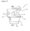
- There has traditionally been a submerged pump for sewage such as that illustrated in
Figure 10 . Apump impeller 111 as illustrated inFigure 9 is used within the submerged pump (see Patent Literature 1). Thepump impeller 111 is generally in a cylindrical shape, which includes anintake port 129 formed at one end and adischarge port 134 formed laterally on the side of the other end, and aspiral flow channel 135 partitioned and formed therein, connecting theintake port 129 with thedischarge port 134. Thepump impeller 111 further includes aflange portion 140 that protrudes outward along the circumferential surface of thepump impeller 111 from a portion closer to the intake port than thedischarge port 134 on the circumferential surface and separates the intake port side from the discharge port side. - The
pump impeller 111 is contained in apump casing 112 and connected to a closed-type submergedmotor 113 for rotatably driving thepump impeller 111. The submergedmotor 113 includes amotor 116 having astator 114 and arotor 115 and amotor casing 117 that covers themotor 116. Adriving shaft 118 extending vertically is provided at the center portion of therotor 115. Thedriving shaft 118 is rotatably supported bybearings pump impeller 111 is then connected to the lower end portion of thedriving shaft 118. - A
pump chamber 126, which is partitioned by aninner wall 125 that is recessed in a semicircular shape in its cross section, is formed within thepump casing 112. Adischarge portion 138 of thepump impeller 111 is contained in thepump chamber 126. Anintake portion 121 that protrudes downward is formed in the lower portion of thepump casing 112. Anintake port 122 that is open downward is formed in theintake portion 121. Adischarge portion 123 that protrudes laterally is formed on the side portion of thepump casing 112. Thedischarge portion 123 includes adischarge port 124 formed therein, which is open laterally. - The
pump impeller 111 is provided with anintake portion 127 and adischarge portion 128 axially from the lower side toward the upper side in this order. Theintake portion 127 and thedischarge portion 128 are both formed generally in a cylindrical shape, and thedischarge portion 128 is constructed to have a diameter larger than theintake portion 127. Thedischarge portion 128 is separated from theintake portion 127 by theflange portion 140 that protrudes outward from the circumferential surface of thepump impeller 11. Anintake port 129 that is open downward is formed at the lower end of theintake portion 127 of thepump impeller 111. The upper side of thedischarge portion 128 is covered by an upper end wall. In other words, the upper side of thepump impeller 111 is hermetically closed by the upper end wall. A hole is provided at the center portion of the upper end wall for inserting a distal end of the drivingshaft 118, and a periphery of the hole constitutes amounting portion 131 for mounting thedriving shaft 118. Additionally, thereference numeral 137 denotes a secondary flow channel and thereference numeral 138 denotes a secondary blade. - Patent Literature 1: Japanese Patent No.
4713066 - The prior art described above, however, has an inevitable problem: when a conventional pump impeller rotates, a large radial load may be generated. In this respect, description will be made in detail.
- In the
pump impeller 111 according to the invention disclosed in Patent Literature 1, one flow channel continues from theintake port 129 to thedischarge port 134. In other words, thepump impeller 111 is adapted to take in sewage from theintake port 129 that is open downward in coaxial with thedriving shaft 118, and the sewage is drained from thedischarge port 134 through the one spiral flow channel. In this case, the area where the spiral flow channel is formed is weightless because it is hollow space. On the other hand, the area forming the wall of thepump impeller 111 has weight. For this reason, the weight of thepump impeller 111 is significantly eccentrically distributed in the circumference direction with respect to the axis (center of rotation) of thedriving shaft 118. Whensuch pump impeller 111 rotates, the deviation of the weight of fluid also increases with respect to the center of rotation, which is likely to cause a radial load. - In view of the above problem, it is conceivable to stabilize the weight balance (dynamic balance) of the pump impeller and then add a weight for cancelling the radial load. Specifically, in order to remove unbalance of the weight in the circumference direction of the pump impeller, part of the wall of the pump impeller is thinned or conversely the wall is thickened to correct the balance, and then a weight for cancelling the radial load is added in the opposite direction. Such an effort, however, is limited per se. The reason is that because sewage flows in the spiral flow channel of the pump impeller and the weight of the sewage itself is added to the pump impeller, the radial load associated with rotation varies, which cannot be cancelled by a mass calculated with fresh water. In addition, even if the weight of the sewage itself is previously taken into consideration, the mixing ratio of sewage flowing from time to time varies, and thus it is impossible for a conventional pump impeller having only one spiral flow channel to remove or reduce the radial load. In view of the problem described above, it is desirable to stabilize the fluid balance.
- The above-mentioned "dynamic balance" is defined herein as displacement of the center of gravity and the center of moment with respect to the axis of rotation when an impeller is rotated in the atmosphere. The dynamic balance can be removed by a correction such as thinning of the wall as described above. The fluid balance refers to balance in the case where a fluid is flowing in a channel while a pump impeller is rotating. Even if the dynamic balance is optimized (zero weight unbalance), the area of water (sewage) in the pump impeller is eccentric with respect to the axis of rotation when the pump impeller is rotated under water. This causes fluid unbalance and a force (which is referred to as a radial load) is applied to the pump impeller via the wall pressure. A large radial load may cause vibration, and thus efforts have been made to cancel the load, such as by applying a weight. In this respect, a multi-channel pump impeller such as that in the present invention can significantly reduce the radial load because the mass distribution of the water area is less likely to be nonaxisymmetric as compared to a single-channel pump impeller. In view of the above description, a specific solution to the problem is as described below.
- The present invention, which has been made in view of the above problem, provides in a first aspect a pump impeller for a non-clogging submerged pump including a generally cylindrical body, an intake port provided in a center of a lower end surface of the body, a discharge port that is open in a side surface of the body, and a flow channel passing from the intake port to the discharge port within the body. The flow channel includes a plurality of flow channels, and the flow channels have their size, shape, and position defined such that fluid unbalance is reduced with respect to an axis of rotation.
- According to the configuration, sewage taken in from the intake port is divided and flows into each of the flow channels. At this time, fluid unbalance is less likely to occur with respect to the axis of rotation because the flow channels are designed to reduce the fluid unbalance, and thus the occurrence of radial load associated with rotation of the pump impeller can significantly be suppressed.
- In a second aspect, the flow channel includes two or more flow channels. According to the configuration, sewage is drained more than once per revolution of the pump impeller, and thus pressure variation during drainage can be suppressed.
- In a third aspect, a cross-sectional area of the flow channel varies between the intake port and the discharge port. In the pump impeller according to the present invention, when sewage separates from a surface of the flow channel near the discharge port, sewage may be prevented from being taken in from the intake port. Accordingly, the varying cross-sectional area is provided in some positions in order to maintain the pressure above a predetermined level.
- In a fourth aspect, a cross-sectional shape of the flow channel varies between the intake port and the discharge port. Furthermore, in a fifth aspect, the cross-sectional shape of the flow channel changes from circular to generally rectangular or elliptic from the intake port toward the discharge port. The intake port is circular and an upstream portion of the flow channel is also circular; while the circumferential surface of the pump impeller has a shape similar to that of a circumferential surface of a cylinder. Accordingly, the cross-sectional shape needs to be changed near the discharge port in order to secure a constant cross-sectional area.
- In a sixth aspect, an inner wall surface of the flow channel is formed of a continuous curved surface. According to the configuration, foreign matters in sewage flow smoothly in the flow channel so that the occurrence of clogging or the like due to the foreign matters can be prevented.
- In a seventh aspect, inner walls close to a junction of at least two of the flow channels have a surface roughness different from each other. In such a configuration, elongated fibrous foreign matters may be divided and flow into two flow channels at a junction close to the intake port. With a surface roughness different from one flow channel to another, however, the frictional resistance is lower on the side of a flow channel having a smoother surface, so that the foreign matters are likely to flow in the side of the flow channel.
- In an eighth aspect, all of the flow channels have the same size and shape, and are disposed at an equal angular interval with respect to the axis of rotation. According to the configuration, sewage taken in from the intake port is divided and flows into each of the flow channels. At this time, since the flow channels have the same size and shape, and are disposed in positions located at an equal angular interval with respect to the axis of rotation, no weight unbalance with respect to the axis of rotation occurs, and thus the occurrence of radial load associated with rotation of the pump impeller can be minimized.
- Furthermore, a submerged pump is characterized by including a pump impeller according to any one of the first to eighth aspects, a pump casing that contains the pump impeller; and a motor that drives the pump impeller. According to the configuration, a pump having a good fluid balance can be realized when assembled and operated as a pump, without problems such as noise and vibration.
- According to the present invention, as an example, the following advantages can be attained by adopting aspects as described above.
- 1. An average radial load can be reduced in operation because the fluid balance of the pump impeller can be achieved with respect to the axis of rotation.
- 2. Along with the reduction in the radial load, noise and vibration can be reduced. In addition, the bearing can be replaced with one that has a smaller capacity, and even when a conventional bearing is still used, the rated number of revolution of the pump impeller can be increased.
- 3. Since a plurality of discharge ports are provided and sewage is drained more than once per revolution of the pump impeller, the variation in drainage pressure can be reduced.
- 4. Since an intake flow channel near the intake port is a straight flow channel coincident with the axis of rotation, the flow channel length in an entrance portion is reduced. This allows the flow to enter smoothly, so that the loss is reduced and the hydraulic efficiency is expected to be improved.
-
-
Figure 1(A) illustrates one flow channel, and is a perspective view illustrating the shape of the flow channel. -
Figure 1(B) illustrates one flow channel, and is a plan view. -
Figure 2(A) illustrates two flow channels used in a pump impeller according to an embodiment of the preset invention, and is a perspective view illustrating the shape of the flow channels. -
Figure 2(B) illustrates two flow channels used in a pump impeller according to an embodiment of the preset invention, and is a plan view. -
Figure 3(A) illustrates a pump impeller provided with the flow channels disclosed inFigures 2(A) and 2(B) , and is a perspective view seen from the intake port side. -
Figure 3(B) illustrates a pump impeller provided with the flow channels disclosed inFigures 2(A) and 2(B) , and is a side view. -
Figure 4(A) illustrates the pump impeller disclosed inFigures 3(A) and 3(B) , and is a plan view. -
Figure 4(B) illustrates the pump impeller disclosed inFigures 3(A) and 3(B) , and is a side view. -
Figure 4(C) illustrates the pump impeller disclosed inFigures 3(A) and 3(B) , and is a bottom view (intake port side). -
Figure 5(A) is a sectional view of the pump impeller disclosed inFigures 4(A), 4(B) and 4(C) , taken along theline 5A-5A inFigure 4(A) . -
Figure 5(B) is a sectional view of the pump impeller disclosed inFigures 4(A), 4(B) and 4(C) , taken along theline 5B-5B inFigure 4(B) . -
Figure 6(A) illustrates three flow channels used in a pump impeller according to a second embodiment of the preset invention, and is a perspective view illustrating the shape of the flow channels. -
Figure 6(B) illustrates three flow channels used in a pump impeller according to a second embodiment of the preset invention, and is a plan view. -
Figure 7 is a sectional view of the pump impeller disclosed inFigure 6 . -
Figure 8(A) is a sectional view illustrating a pump impeller with flow channels each having a different size and shape, which is a combination of one thin flow channel and two thick flow channels. -
Figure 8(B) is a sectional view illustrating a pump impeller with flow channels each having a different size and shape, in which angular intervals are different for each flow channel. -
Figure 9 is a sectional view illustrating an example configuration for a submerged pump provided with a pump impeller according to an embodiment of the preset invention. -
Figure 10 is a side view illustrating a conventional pump impeller. -
Figure 11 is a sectional view illustrating a submerged pump provided with the pump impeller disclosed inFigure 10 . - A pump impeller according to an embodiment of the preset invention will now be described with reference to
Figures 1 to 8 . - The pump impeller of the embodiment includes a plurality of flow channels that bring an intake port coaxial with an axis of rotation into communication with a discharge port on an outer circumferential portion and the flow channels are disposed at an equal angular interval with respect to the axis of rotation by logical add. Although the number of flow channels are not limited,
Figures 3(A) to 5(B) illustrate an embodiment with two flow channels, andFigures 6(A) to 8(B) illustrate an embodiment with three flow channels. The flow channels are bent in a curved shape between the intake port and the discharge port. As an example, the pump impeller is produced by casting. However, as long as strength or corrosion resistance can be secured, any other metal or non-metal material may be used. -
Figure 1(A) is an image by computer graphics, illustrating aflow channel 3 used in a pump impeller. Referring to the shape of theflow channel 3 from anintake port 5 toward adischarge port 7, the flow channel is coaxial with the axis of rotation C near theintake port 5. In other words, the central axis of theflow channel 3 near theintake port 5 is parallel to and coincident with the axis of rotation C. On the downstream side, the central axis of theflow channel 3 extends downward and then radially outward with respect to the axis of rotation C. A transitional portion from the direction of the axis of rotation to the radially outward direction is formed of a continuous curve. - While the central axis of the
flow channel 3 extends radially outward, it further extends circumferentially with respect to the axis of rotation C. Accordingly, as a result of a combination of the radially outward component with the circumferential component, the central axis of theflow channel 3 extends outward in a spiral manner. Furthermore, the cross-sectional shape of theflow channel 3 is a complete circle near theintake port 5, while it is rectangular near thedischarge port 7. Accordingly, a transitional region from theintake port 5 toward thedischarge port 7 continuously changes such that a circle gradually turns into a rectangle. Note that even though the term rectangle is used, corner portions do not have right-angled surfaces but are formed of curves of a small radius of curvature. This arrangement is for preventing foreign matters from being accumulated in the corner portions. -
Figure 1(A) illustrates a logical shape of theflow channel 3; when applied to an actual pump impeller, an outer edge of the pump impeller is circular about the axis of rotation C. Specifically, an ellipse illustrated inFigure 1(A) defines the outer edge of the pump impeller. Accordingly, anactual flow channel 3 formed in the pump impeller has a shape as illustrated inFigure 1(B) in which thedischarge port 7 is formed over a broad angular range. The shape of theflow channel 3 used in a pump impeller has been described. This description, however, is of a case in which only oneflow channel 3 is provided. As described below, the embodiment is characterized by a combination of two flow channels, and thus a specific example thereof will be described. -
Figure 2(A) illustrates a configuration that includes twoflow channels flow channels flow channel 3 inFigures 1(A) and 1(B) is rotationally copied and disposed at an equal angular interval. Accordingly, as illustrated inFigure 2(B) , regions where theflow channels intake port 15 extend in directions mutually spaced by 180° (opposite directions). The logical add used herein refers to simply combining two flow channels with a common intake port. -
Figure 2(B) illustratesactual flow channels Figure 1(B) . As illustrated, theflow channels discharge ports Figure 1(B) . -
Figures 3 are views of apump impeller 11 according to the embodiment created by computer graphics. In particular,Figure 3(A) is a view seen obliquely from theintake port 15 side, andFigure 3(B) is a view seen from the side. Flow channels formed inside thepump impeller 11 illustrated in the figure are theflow channels Figure 2(B) . As apparent fromFigure 3(B) , the cross-sectional shape of a flow channel is nearly circular on the right side (upstream side) of the axis of rotation C, while it is in a shape forming a part of a rectangle on the left side (downstream side) of the axis of rotation. -
Figures 4(A), 4(B) and 4(C) illustrate thepump impeller 11 of the embodiment, and are a plan view, a side view, and a bottom view, respectively. As illustrated inFigure 4(A) and 4(B) , acylindrical hub 14 is formed in a region of the central axis C, and thehub 14 is adapted to receive an inserted driving shaft (not illustrated) of a driving motor. For example, thepump impeller 11 is adapted to rotate at the number of revolution on the order of 1500 rpm. However, if efficiency can be improved, the pump impeller may be rotated at any number of revolution that is lower or higher than 1500 rpm. -
Figure 5(A) is a sectional view taken along theline 5A-5A inFigure 4(B) . As illustrated, thepump impeller 11 includes anintake port 15 formed therein that is open to one side of the central axis C, and sewage is taken in as thepump impeller 11 rotates. The sewage is then transported from theintake port 15 circumferentially outward along theflow channels discharge ports -
Figure 5(B) is a sectional view taken along theline 5B-5B inFigure 4(B) . As illustrated, theflow channels intake port 15 extend radially outward in a spiral manner, and providedischarge ports pump impeller 11. Accordingly, other portions than the flow channels are wall portions constituting thepump impeller 11. As apparent from the figure, thedischarge ports flow channels discharge ports Figure 5(B) , apump casing 16 is also illustrated for convenience in explanation. Description will be made later as to how thepump impeller 11 and thepump casing 16 are related. - The
intake port 15 is cylindrical and is open so as to be coaxial with the axis of rotation C. Accordingly, theintake port 15 is formed as substantially common one port by logical add. Theintake port 15 is disposed so as to be open downward when it is actually installed in a pump. The inner diameter of theintake port 15 is set based on the volume of solid matters contained in sewage handled by thepump impeller 11. - As illustrated in
Figures 5(A) and 5(B) , theflow channels intake port 15 into two flow channels, as described above. Theflow channels intake port 15 up to the junction. On the other hand, the cross-sectional area is gradually reduced from the junction toward the downstream. This is because if the cross-sectional area of each of theflow channels intake port 15 after branching, the sum of the areas doubles and the pressure of sewage decreases, which may cause a separation phenomenon of sewage from an inner surface of theflow channels intake port 15 would be anticipated. For this reason, the cross-sectional area of theflow channels intake port 15, as described above. - The rate of decrease in the cross-sectional area of the
flow channels pump impeller 11. For example, when the viscosity of sewage is high, the separation phenomenon is less likely to occur so that the rate of decrease in the cross-sectional area may be small. When the number of revolution of thepump impeller 11 is high, then the separation phenomenon is likely to occur so that the rate of decrease in the cross-sectional area may desirably be increased. As for a specific rate of decrease in the cross-sectional area, for example, the cross-sectional area of theflow channels intake port 15. - The inner wall surfaces of the
flow channels flow channels - On the other hand, when the
flow channels flow channels flow channel 13A is smoothened, and the inner surface of theother flow channel 13B is formed in a roughened state (for example, as-cast state). In such a case, the frictional resistance on the fibrous object is lower on the smooth inner surface, and to the contrary, the coefficient of friction is higher on the rough inner surface. Such imbalance in the coefficient of friction allows the fibrous object to flow in the side of the flow channel having the smooth inner surface. In this way, a possible problem that may be associated with twoflow channels - Based on
Figure 5(B) , operation of thepump impeller 11 according to the embodiment will now be described. Thepump impeller 11 rotates clockwise inFigure 5(B) . At this time, sewage preset in the (first)flow channel 13A of thepump impeller 11 is subjected to a centrifugal force associated with the rotation. For this reason, the sewage tends to move outward in the radial direction of thepump impeller 11. When thedischarge port 17A of thepump impeller 11 faces adrain port 18 of thepump casing 16, the sewage is then delivered to the outside of the pump through thedischarge port 17A and thedrain port 18. - When the
pump impeller 11 further rotates clockwise, thenext discharge port 17B faces thedrain port 18 of thepump casing 16. Sewage preset in the (second)flow channel 13B of thepump impeller 11 is also subjected to a centrifugal force associated with the rotation. The sewage is thus delivered to the outside of the pump through thedischarge port 17B and thedrain port 18, in the same way as described above. This means that the sewage is drained twice per revolution of thepump impeller 11. If the amount of sewage to be drained is the same as that for a conventional pump impeller having only one flow channel, the amount of drain in one turn is halved because the drainage of sewage is divided into two. As a result, pulsation (pressure variation) occurring while the sewage is drained is kept low. - As described above, when sewage is drained from the
pump impeller 11, theflow channels intake port 15. Accordingly, the cross-sectional area of theflow channels flow channels discharge ports flow channels intake port 15 toward thedischarge ports - Furthermore, the
flow channels intake port 15 and thedischarge ports intake port 15 to dischargeports - All inner wall surfaces of the
flow channels flow channels flow channels discharge ports intake port 15 to thedischarge ports flow channels flow channels -
Figures 6(A), 6(B) and7 are views for describing apump impeller 21 with three flow channels according to a second embodiment. In particular,Figure 6(A) corresponds toFigure 2(A) of the first embodiment,Figure 6(B) corresponds toFigure 2(B) , andFigure 7 corresponds toFigure 5 . Here,Figures 6(A) and 6(B) illustrate threeflow channels intake port 25. - Similarly to the first embodiment, the
flow channels Figures 1(A) and 1(B) and disposing them at an equal angular interval with respect to the central axis C. Accordingly, as illustrated inFigure 6(B) , regions where theflow channels intake port 25 extend in directions mutually spaced by 120°. -
Figure 6(B) illustratesactual flow channels Figure 2(B) . Near the outer edge of the pump impeller 23,discharge ports Figure 2(B) .Figure 7 is a sectional view illustrating a pump impeller housed in anactual pump casing 26. - In the
pump impeller 21 according to the embodiment, sewage is drained by one third per rotation from threeflow channels pump impeller 11 of the first embodiment with two flow channels. - The description above has been made as to a pump impeller, all flow channels of which have the same size and shape, and are disposed at an equal angular interval about the respective axis of rotation. However, a pump impeller capable of reducing fluid balance is not necessarily limited to the pump impeller of the above configuration. In other words, the fluid balance can be reduced when one flow channel is thinner and the remaining two flow channels are thicker, as illustrated in
Figure 8(A) . Conversely, a combination of two thinner flow channels and one thicker flow channel is also possible. - Furthermore, as illustrated in
Figure 8(B) , the fluid balance can be reduced when angular intervals between flow channels are unequal. In this way, by varying angular intervals, an intermittent flow (pulsation) in a volute can be increased to enhance drainability for foreign matters. -
Figure 9 is a sectional view of a submergedpump 60 provided with thepump impeller 11 according to the embodiment as described above. Thepump impeller 11 is contained in apump casing 62 and connected to a closed-type submergedmotor 63 for rotatably driving thepump impeller 11. The submergedmotor 63 includes amotor 66 having astator 64 and arotor 65, and amotor casing 67 that covers themotor 66. A drivingshaft 68 extending vertically is provided at the center portion of therotor 65. The drivingshaft 68 is rotatably supported bybearings pump impeller 11 is then connected to the lower end portion of the drivingshaft 68. - A
pump chamber 76, which is partitioned by aninner wall 75 that is recessed in a semicircular shape in its cross section, is formed within thepump casing 62. Adischarge portion 68 of thepump impeller 11 is contained in thepump chamber 76. Anintake portion 71 that protrudes downward is formed in the lower portion of thepump casing 62. Anintake port 72 that is open downward is formed in theintake portion 71. Adrain portion 73 that protrudes laterally is formed on the side portion of thepump casing 62. Thedrain portion 73 includes adrain port 74 formed therein, which is open laterally. - A pump impeller according to the preset invention can be particularly useful for a submerged pump for sewage.
-
- 1, 11, 21
- pump impeller
- 3
- flow channel
- 5
- intake port
- 7
- discharge port
- 13A, 13B
- flow channel
- 15
- intake port
- 17A, 17B
- discharge port
- 23A, 23B, 23C
- flow channel
- 25
- intake port
- 26
- pump casing
- 27A, 27B, 27C
- discharge port
- C
- axis of rotation
Claims (9)
- A pump impeller for a non-clogging submerged pump comprising:a substantially cylindrical body;an intake port provided in a center of a lower end surface of the body;a discharge port that is open in a side surface of the body; anda flow channel passing from the intake port to the discharge port within the body,wherein the flow channel includes a plurality of flow channels, andthe flow channels have their size, shape, and position defined such that fluid unbalance is reduced with respect to an axis of rotation.
- The pump impeller according to claim 1, wherein the flow channel includes two or more flow channels.
- The pump impeller according to claim 1 or 2, wherein a cross-sectional area of the flow channel varies between the intake port and the discharge port.
- The pump impeller according to any one of claims 1 to 3, wherein a cross-sectional shape of the flow channel varies between the intake port and the discharge port.
- The pump impeller according to claim 4, wherein the cross-sectional shape of the flow channel changes from circular to generally rectangular or elliptic from the intake port toward the discharge port.
- The pump impeller according to any one of claims 1 to 5, wherein an inner wall surface of the flow channel is formed of a continuous curved surface.
- The pump impeller according to any one of claims 1 to 6, wherein inner walls close to a junction of at least two of the flow channels have a surface roughness different from each other.
- The pump impeller according to any one of claims 1 to 7, wherein all of the flow channels have the same size and shape, and are disposed at an equal angular interval with respect to the axis of rotation.
- A submerged pump comprising:the pump impeller according to any one of claims 1 to 8;a pump casing that contains the pump impeller; anda motor that drives the pump impeller.
Applications Claiming Priority (2)
| Application Number | Priority Date | Filing Date | Title |
|---|---|---|---|
| JP2013141415A JP6351216B2 (en) | 2013-07-05 | 2013-07-05 | Pump blade for submersible pump and submersible pump equipped with the same |
| PCT/JP2014/060657 WO2015001830A1 (en) | 2013-07-05 | 2014-04-15 | Pump blade for submerged pump and submerged pump having same |
Publications (3)
| Publication Number | Publication Date |
|---|---|
| EP2930367A1 true EP2930367A1 (en) | 2015-10-14 |
| EP2930367A4 EP2930367A4 (en) | 2016-11-02 |
| EP2930367B1 EP2930367B1 (en) | 2020-05-27 |
Family
ID=52143424
Family Applications (1)
| Application Number | Title | Priority Date | Filing Date |
|---|---|---|---|
| EP14819908.6A Revoked EP2930367B1 (en) | 2013-07-05 | 2014-04-15 | Pump blade for submerged pump and submerged pump having same |
Country Status (7)
| Country | Link |
|---|---|
| US (1) | US20160108927A1 (en) |
| EP (1) | EP2930367B1 (en) |
| JP (1) | JP6351216B2 (en) |
| CN (1) | CN104662302B (en) |
| BR (1) | BR112015009797B1 (en) |
| DK (1) | DK2930367T3 (en) |
| WO (1) | WO2015001830A1 (en) |
Cited By (1)
| Publication number | Priority date | Publication date | Assignee | Title |
|---|---|---|---|---|
| WO2021049925A1 (en) * | 2019-09-12 | 2021-03-18 | OCHOA BARRAZA, Antonio | Impeller having a double internal turbine |
Families Citing this family (5)
| Publication number | Priority date | Publication date | Assignee | Title |
|---|---|---|---|---|
| JP6351216B2 (en) | 2013-07-05 | 2018-07-04 | 株式会社荏原製作所 | Pump blade for submersible pump and submersible pump equipped with the same |
| CN105736391B (en) * | 2016-02-18 | 2018-11-02 | 广州道动新能源有限公司 | A kind of irrigation system of wind energy driving |
| KR101816766B1 (en) | 2016-09-02 | 2018-01-09 | 이신구 | Energy-saving pump |
| KR101712381B1 (en) * | 2016-11-21 | 2017-03-16 | 고일영 | Impeller for manhole pump |
| RU2735971C1 (en) * | 2020-02-25 | 2020-11-11 | Игорь Олегович Стасюк | Impeller of blade pump stage |
Family Cites Families (22)
| Publication number | Priority date | Publication date | Assignee | Title |
|---|---|---|---|---|
| US1975274A (en) * | 1932-08-17 | 1934-10-02 | Byron Jackson Co | Centrifugal pump impeller |
| JPS52107605A (en) * | 1976-03-05 | 1977-09-09 | Hitachi Ltd | Sewage pump |
| JPS5591797A (en) * | 1978-12-29 | 1980-07-11 | Ebara Corp | Vortex type pump |
| DE3211230A1 (en) * | 1982-03-26 | 1983-09-29 | Paul Pleiger Maschinenfabrik, 5810 Witten | centrifugal pump, especially for dirty water and effluent |
| SE461996B (en) | 1988-09-14 | 1990-04-23 | Flygt Ab | CLOSED LOAD WHEEL FOR PUMPS, COMPRESSORS, FLATS ETC OF CENTRIFUGAL OR HALFAXIAL TYPE |
| JPH09209963A (en) * | 1996-02-03 | 1997-08-12 | Nakase Noriyuki | Pump for carrying solid matter |
| US6405748B1 (en) | 1999-03-22 | 2002-06-18 | David Muhs | Trailer and fuel tank assembly |
| JP2000297789A (en) | 1999-04-14 | 2000-10-24 | Tokyo Electric Power Co Inc:The | Axial flow compressor |
| FI110275B (en) | 2001-04-27 | 2002-12-31 | Grundfos Management As | Impeller for a pump |
| US6837684B2 (en) | 2002-10-25 | 2005-01-04 | Grundfos Management A/S | Pump impeller |
| JP4713066B2 (en) | 2003-07-18 | 2011-06-29 | 新明和工業株式会社 | Impeller and sewage treatment pump equipped therewith |
| SE0402840L (en) * | 2004-11-19 | 2006-04-11 | Itt Mfg Enterprises Inc | Impeller |
| EP1943169B1 (en) * | 2005-10-12 | 2014-06-04 | K-TRON Technologies, Inc. | Bulk material pump feeder with compliant disks to reduce disk jamming |
| EP1795758A1 (en) | 2005-12-09 | 2007-06-13 | Grundfos Management A/S | Impeller for a pump unit and pump unit |
| MX2007002934A (en) | 2007-03-12 | 2008-09-17 | Calidad Empresarial Dinamica Sa De Cv | Highly effective centrifuge pump and method for designing the drive mechanism thereof. |
| CN201377436Y (en) * | 2009-03-31 | 2010-01-06 | 长沙水泵厂有限公司 | Structure for double-suction multistage horizontal split pump |
| CA2701515C (en) * | 2009-04-24 | 2014-04-15 | Syncrude Canada Ltd. | Centrifugal pump having wear protected vanes |
| PL216284B1 (en) | 2010-03-22 | 2014-03-31 | Fundacja Rozwoju Kardiochirurgii Im Prof Zbigniewa Religi | Single-jet centrifugal pump |
| TWI464322B (en) * | 2010-12-14 | 2014-12-11 | Delta Electronics Inc | Centrifugal fan |
| KR101070136B1 (en) * | 2011-02-22 | 2011-10-05 | 이재웅 | Impeller including cylinder type vanes |
| JP2013141415A (en) | 2012-01-06 | 2013-07-22 | Ihi Corp | Method and device for producing monosaccharide, and method and device for producing ethanol |
| JP6351216B2 (en) | 2013-07-05 | 2018-07-04 | 株式会社荏原製作所 | Pump blade for submersible pump and submersible pump equipped with the same |
-
2013
- 2013-07-05 JP JP2013141415A patent/JP6351216B2/en active Active
-
2014
- 2014-04-15 US US14/439,879 patent/US20160108927A1/en not_active Abandoned
- 2014-04-15 CN CN201480002515.3A patent/CN104662302B/en active Active
- 2014-04-15 WO PCT/JP2014/060657 patent/WO2015001830A1/en active Application Filing
- 2014-04-15 BR BR112015009797-9A patent/BR112015009797B1/en active IP Right Grant
- 2014-04-15 DK DK14819908.6T patent/DK2930367T3/en active
- 2014-04-15 EP EP14819908.6A patent/EP2930367B1/en not_active Revoked
Cited By (1)
| Publication number | Priority date | Publication date | Assignee | Title |
|---|---|---|---|---|
| WO2021049925A1 (en) * | 2019-09-12 | 2021-03-18 | OCHOA BARRAZA, Antonio | Impeller having a double internal turbine |
Also Published As
| Publication number | Publication date |
|---|---|
| CN104662302A (en) | 2015-05-27 |
| EP2930367B1 (en) | 2020-05-27 |
| US20160108927A1 (en) | 2016-04-21 |
| JP6351216B2 (en) | 2018-07-04 |
| EP2930367A4 (en) | 2016-11-02 |
| JP2015014251A (en) | 2015-01-22 |
| BR112015009797A8 (en) | 2017-08-01 |
| WO2015001830A1 (en) | 2015-01-08 |
| CN104662302B (en) | 2017-11-28 |
| BR112015009797B1 (en) | 2022-03-15 |
| DK2930367T3 (en) | 2020-06-29 |
| BR112015009797A2 (en) | 2017-07-11 |
Similar Documents
| Publication | Publication Date | Title |
|---|---|---|
| EP2930367B1 (en) | Pump blade for submerged pump and submerged pump having same | |
| RU2659843C2 (en) | Rotor for centrifugal flowing machine and centrifugal flowing machine | |
| JP4842676B2 (en) | Centrifugal pump impeller and centrifugal pump impeller balance adjustment method | |
| JP5044105B2 (en) | Centrifugal pump impeller and centrifugal pump equipped with the impeller | |
| JP5709898B2 (en) | Rotating machine | |
| WO2012033192A1 (en) | Sealing structure and centrifugal compressor | |
| CN102686885A (en) | Impeller for pump, and submersible pump provided with same | |
| KR102200789B1 (en) | High efficiency low specific speed centrifugal pump | |
| JP2006291917A (en) | Impeller for centrifugal pump and centrifugal pump having the same | |
| US10947988B2 (en) | Impeller and centrifugal compressor | |
| JP2011144691A (en) | Water discharge pump | |
| CN111448396B (en) | Variable stator blade and compressor | |
| US10859092B2 (en) | Impeller and rotating machine | |
| US11401944B2 (en) | Impeller and centrifugal compressor | |
| JP2006132432A (en) | Liquid pump | |
| US10082154B2 (en) | Intake channel arrangement for a volute casing of a centrifugal pump, a flange member, a volute casing for a centrifugal pump and a centrifugal pump | |
| JP4731122B2 (en) | Liquid pump | |
| JP2011236915A (en) | Impeller device for centrifugal pump and centrifugal pump with the same | |
| JP7330508B2 (en) | impeller and submersible pump | |
| CN205823725U (en) | Immersible pump pump blade and possess the immersible pump of this immersible pump pump blade | |
| US10107288B2 (en) | Housing for scroll compressor and scroll compressor | |
| TW201627578A (en) | Pump blade for underwater pump and underwater pump having the pump blade | |
| JP6099988B2 (en) | Water pump | |
| JP5767911B2 (en) | Impeller and submersible pump | |
| CN102345630A (en) | Impeller used for pump and pump |
Legal Events
| Date | Code | Title | Description |
|---|---|---|---|
| PUAI | Public reference made under article 153(3) epc to a published international application that has entered the european phase |
Free format text: ORIGINAL CODE: 0009012 |
|
| 17P | Request for examination filed |
Effective date: 20150430 |
|
| AK | Designated contracting states |
Kind code of ref document: A1 Designated state(s): AL AT BE BG CH CY CZ DE DK EE ES FI FR GB GR HR HU IE IS IT LI LT LU LV MC MK MT NL NO PL PT RO RS SE SI SK SM TR |
|
| AX | Request for extension of the european patent |
Extension state: BA ME |
|
| DAX | Request for extension of the european patent (deleted) | ||
| RA4 | Supplementary search report drawn up and despatched (corrected) |
Effective date: 20160930 |
|
| RIC1 | Information provided on ipc code assigned before grant |
Ipc: F04D 7/04 20060101AFI20160926BHEP Ipc: F04D 13/02 20060101ALI20160926BHEP Ipc: F04D 29/22 20060101ALI20160926BHEP Ipc: F04D 29/66 20060101ALI20160926BHEP |
|
| STAA | Information on the status of an ep patent application or granted ep patent |
Free format text: STATUS: EXAMINATION IS IN PROGRESS |
|
| 17Q | First examination report despatched |
Effective date: 20170821 |
|
| GRAP | Despatch of communication of intention to grant a patent |
Free format text: ORIGINAL CODE: EPIDOSNIGR1 |
|
| STAA | Information on the status of an ep patent application or granted ep patent |
Free format text: STATUS: GRANT OF PATENT IS INTENDED |
|
| INTG | Intention to grant announced |
Effective date: 20191115 |
|
| GRAS | Grant fee paid |
Free format text: ORIGINAL CODE: EPIDOSNIGR3 |
|
| GRAJ | Information related to disapproval of communication of intention to grant by the applicant or resumption of examination proceedings by the epo deleted |
Free format text: ORIGINAL CODE: EPIDOSDIGR1 |
|
| GRAL | Information related to payment of fee for publishing/printing deleted |
Free format text: ORIGINAL CODE: EPIDOSDIGR3 |
|
| STAA | Information on the status of an ep patent application or granted ep patent |
Free format text: STATUS: EXAMINATION IS IN PROGRESS |
|
| INTC | Intention to grant announced (deleted) | ||
| GRAR | Information related to intention to grant a patent recorded |
Free format text: ORIGINAL CODE: EPIDOSNIGR71 |
|
| STAA | Information on the status of an ep patent application or granted ep patent |
Free format text: STATUS: GRANT OF PATENT IS INTENDED |
|
| GRAA | (expected) grant |
Free format text: ORIGINAL CODE: 0009210 |
|
| STAA | Information on the status of an ep patent application or granted ep patent |
Free format text: STATUS: THE PATENT HAS BEEN GRANTED |
|
| AK | Designated contracting states |
Kind code of ref document: B1 Designated state(s): AL AT BE BG CH CY CZ DE DK EE ES FI FR GB GR HR HU IE IS IT LI LT LU LV MC MK MT NL NO PL PT RO RS SE SI SK SM TR |
|
| INTG | Intention to grant announced |
Effective date: 20200420 |
|
| REG | Reference to a national code |
Ref country code: GB Ref legal event code: FG4D |
|
| REG | Reference to a national code |
Ref country code: CH Ref legal event code: EP |
|
| REG | Reference to a national code |
Ref country code: AT Ref legal event code: REF Ref document number: 1274827 Country of ref document: AT Kind code of ref document: T Effective date: 20200615 |
|
| REG | Reference to a national code |
Ref country code: DE Ref legal event code: R096 Ref document number: 602014065995 Country of ref document: DE |
|
| REG | Reference to a national code |
Ref country code: DK Ref legal event code: T3 Effective date: 20200624 |
|
| REG | Reference to a national code |
Ref country code: LT Ref legal event code: MG4D |
|
| PG25 | Lapsed in a contracting state [announced via postgrant information from national office to epo] |
Ref country code: IS Free format text: LAPSE BECAUSE OF FAILURE TO SUBMIT A TRANSLATION OF THE DESCRIPTION OR TO PAY THE FEE WITHIN THE PRESCRIBED TIME-LIMIT Effective date: 20200927 Ref country code: SE Free format text: LAPSE BECAUSE OF FAILURE TO SUBMIT A TRANSLATION OF THE DESCRIPTION OR TO PAY THE FEE WITHIN THE PRESCRIBED TIME-LIMIT Effective date: 20200527 Ref country code: FI Free format text: LAPSE BECAUSE OF FAILURE TO SUBMIT A TRANSLATION OF THE DESCRIPTION OR TO PAY THE FEE WITHIN THE PRESCRIBED TIME-LIMIT Effective date: 20200527 Ref country code: PT Free format text: LAPSE BECAUSE OF FAILURE TO SUBMIT A TRANSLATION OF THE DESCRIPTION OR TO PAY THE FEE WITHIN THE PRESCRIBED TIME-LIMIT Effective date: 20200928 Ref country code: GR Free format text: LAPSE BECAUSE OF FAILURE TO SUBMIT A TRANSLATION OF THE DESCRIPTION OR TO PAY THE FEE WITHIN THE PRESCRIBED TIME-LIMIT Effective date: 20200828 Ref country code: NO Free format text: LAPSE BECAUSE OF FAILURE TO SUBMIT A TRANSLATION OF THE DESCRIPTION OR TO PAY THE FEE WITHIN THE PRESCRIBED TIME-LIMIT Effective date: 20200827 Ref country code: LT Free format text: LAPSE BECAUSE OF FAILURE TO SUBMIT A TRANSLATION OF THE DESCRIPTION OR TO PAY THE FEE WITHIN THE PRESCRIBED TIME-LIMIT Effective date: 20200527 |
|
| REG | Reference to a national code |
Ref country code: NL Ref legal event code: MP Effective date: 20200527 |
|
| PG25 | Lapsed in a contracting state [announced via postgrant information from national office to epo] |
Ref country code: RS Free format text: LAPSE BECAUSE OF FAILURE TO SUBMIT A TRANSLATION OF THE DESCRIPTION OR TO PAY THE FEE WITHIN THE PRESCRIBED TIME-LIMIT Effective date: 20200527 Ref country code: BG Free format text: LAPSE BECAUSE OF FAILURE TO SUBMIT A TRANSLATION OF THE DESCRIPTION OR TO PAY THE FEE WITHIN THE PRESCRIBED TIME-LIMIT Effective date: 20200827 Ref country code: HR Free format text: LAPSE BECAUSE OF FAILURE TO SUBMIT A TRANSLATION OF THE DESCRIPTION OR TO PAY THE FEE WITHIN THE PRESCRIBED TIME-LIMIT Effective date: 20200527 Ref country code: LV Free format text: LAPSE BECAUSE OF FAILURE TO SUBMIT A TRANSLATION OF THE DESCRIPTION OR TO PAY THE FEE WITHIN THE PRESCRIBED TIME-LIMIT Effective date: 20200527 |
|
| REG | Reference to a national code |
Ref country code: AT Ref legal event code: MK05 Ref document number: 1274827 Country of ref document: AT Kind code of ref document: T Effective date: 20200527 |
|
| PG25 | Lapsed in a contracting state [announced via postgrant information from national office to epo] |
Ref country code: AL Free format text: LAPSE BECAUSE OF FAILURE TO SUBMIT A TRANSLATION OF THE DESCRIPTION OR TO PAY THE FEE WITHIN THE PRESCRIBED TIME-LIMIT Effective date: 20200527 Ref country code: NL Free format text: LAPSE BECAUSE OF FAILURE TO SUBMIT A TRANSLATION OF THE DESCRIPTION OR TO PAY THE FEE WITHIN THE PRESCRIBED TIME-LIMIT Effective date: 20200527 |
|
| PG25 | Lapsed in a contracting state [announced via postgrant information from national office to epo] |
Ref country code: SM Free format text: LAPSE BECAUSE OF FAILURE TO SUBMIT A TRANSLATION OF THE DESCRIPTION OR TO PAY THE FEE WITHIN THE PRESCRIBED TIME-LIMIT Effective date: 20200527 Ref country code: EE Free format text: LAPSE BECAUSE OF FAILURE TO SUBMIT A TRANSLATION OF THE DESCRIPTION OR TO PAY THE FEE WITHIN THE PRESCRIBED TIME-LIMIT Effective date: 20200527 Ref country code: AT Free format text: LAPSE BECAUSE OF FAILURE TO SUBMIT A TRANSLATION OF THE DESCRIPTION OR TO PAY THE FEE WITHIN THE PRESCRIBED TIME-LIMIT Effective date: 20200527 Ref country code: CZ Free format text: LAPSE BECAUSE OF FAILURE TO SUBMIT A TRANSLATION OF THE DESCRIPTION OR TO PAY THE FEE WITHIN THE PRESCRIBED TIME-LIMIT Effective date: 20200527 Ref country code: RO Free format text: LAPSE BECAUSE OF FAILURE TO SUBMIT A TRANSLATION OF THE DESCRIPTION OR TO PAY THE FEE WITHIN THE PRESCRIBED TIME-LIMIT Effective date: 20200527 Ref country code: ES Free format text: LAPSE BECAUSE OF FAILURE TO SUBMIT A TRANSLATION OF THE DESCRIPTION OR TO PAY THE FEE WITHIN THE PRESCRIBED TIME-LIMIT Effective date: 20200527 |
|
| REG | Reference to a national code |
Ref country code: DE Ref legal event code: R026 Ref document number: 602014065995 Country of ref document: DE |
|
| PG25 | Lapsed in a contracting state [announced via postgrant information from national office to epo] |
Ref country code: PL Free format text: LAPSE BECAUSE OF FAILURE TO SUBMIT A TRANSLATION OF THE DESCRIPTION OR TO PAY THE FEE WITHIN THE PRESCRIBED TIME-LIMIT Effective date: 20200527 Ref country code: SK Free format text: LAPSE BECAUSE OF FAILURE TO SUBMIT A TRANSLATION OF THE DESCRIPTION OR TO PAY THE FEE WITHIN THE PRESCRIBED TIME-LIMIT Effective date: 20200527 |
|
| PLBI | Opposition filed |
Free format text: ORIGINAL CODE: 0009260 |
|
| PLBI | Opposition filed |
Free format text: ORIGINAL CODE: 0009260 |
|
| 26 | Opposition filed |
Opponent name: KSB SE & CO. KGAA Effective date: 20210225 |
|
| 26 | Opposition filed |
Opponent name: GRUNDFOS HOLDING A/S Effective date: 20210226 |
|
| PLAX | Notice of opposition and request to file observation + time limit sent |
Free format text: ORIGINAL CODE: EPIDOSNOBS2 |
|
| PLAZ | Examination of admissibility of opposition: despatch of communication + time limit |
Free format text: ORIGINAL CODE: EPIDOSNOPE2 |
|
| PG25 | Lapsed in a contracting state [announced via postgrant information from national office to epo] |
Ref country code: SI Free format text: LAPSE BECAUSE OF FAILURE TO SUBMIT A TRANSLATION OF THE DESCRIPTION OR TO PAY THE FEE WITHIN THE PRESCRIBED TIME-LIMIT Effective date: 20200527 |
|
| PLBA | Examination of admissibility of opposition: reply received |
Free format text: ORIGINAL CODE: EPIDOSNOPE4 |
|
| PLBB | Reply of patent proprietor to notice(s) of opposition received |
Free format text: ORIGINAL CODE: EPIDOSNOBS3 |
|
| REG | Reference to a national code |
Ref country code: DE Ref legal event code: R119 Ref document number: 602014065995 Country of ref document: DE |
|
| PG25 | Lapsed in a contracting state [announced via postgrant information from national office to epo] |
Ref country code: MC Free format text: LAPSE BECAUSE OF FAILURE TO SUBMIT A TRANSLATION OF THE DESCRIPTION OR TO PAY THE FEE WITHIN THE PRESCRIBED TIME-LIMIT Effective date: 20200527 |
|
| GBPC | Gb: european patent ceased through non-payment of renewal fee |
Effective date: 20210415 |
|
| PG25 | Lapsed in a contracting state [announced via postgrant information from national office to epo] |
Ref country code: LU Free format text: LAPSE BECAUSE OF NON-PAYMENT OF DUE FEES Effective date: 20210415 |
|
| REG | Reference to a national code |
Ref country code: BE Ref legal event code: MM Effective date: 20210430 |
|
| PG25 | Lapsed in a contracting state [announced via postgrant information from national office to epo] |
Ref country code: DE Free format text: LAPSE BECAUSE OF NON-PAYMENT OF DUE FEES Effective date: 20211103 Ref country code: GB Free format text: LAPSE BECAUSE OF NON-PAYMENT OF DUE FEES Effective date: 20210415 Ref country code: FR Free format text: LAPSE BECAUSE OF NON-PAYMENT OF DUE FEES Effective date: 20210430 Ref country code: LI Free format text: LAPSE BECAUSE OF NON-PAYMENT OF DUE FEES Effective date: 20210430 Ref country code: CH Free format text: LAPSE BECAUSE OF NON-PAYMENT OF DUE FEES Effective date: 20210430 |
|
| PG25 | Lapsed in a contracting state [announced via postgrant information from national office to epo] |
Ref country code: IE Free format text: LAPSE BECAUSE OF NON-PAYMENT OF DUE FEES Effective date: 20210415 |
|
| PG25 | Lapsed in a contracting state [announced via postgrant information from national office to epo] |
Ref country code: BE Free format text: LAPSE BECAUSE OF NON-PAYMENT OF DUE FEES Effective date: 20210430 |
|
| REG | Reference to a national code |
Ref country code: DE Ref legal event code: R103 Ref document number: 602014065995 Country of ref document: DE Ref country code: DE Ref legal event code: R064 Ref document number: 602014065995 Country of ref document: DE |
|
| RDAF | Communication despatched that patent is revoked |
Free format text: ORIGINAL CODE: EPIDOSNREV1 |
|
| RDAG | Patent revoked |
Free format text: ORIGINAL CODE: 0009271 |
|
| STAA | Information on the status of an ep patent application or granted ep patent |
Free format text: STATUS: PATENT REVOKED |
|
| PGFP | Annual fee paid to national office [announced via postgrant information from national office to epo] |
Ref country code: DK Payment date: 20230317 Year of fee payment: 10 |
|
| REG | Reference to a national code |
Ref country code: CH Ref legal event code: PL |
|
| 27W | Patent revoked |
Effective date: 20221122 |
|
| PGFP | Annual fee paid to national office [announced via postgrant information from national office to epo] |
Ref country code: IT Payment date: 20230306 Year of fee payment: 10 |
|
| P01 | Opt-out of the competence of the unified patent court (upc) registered |
Effective date: 20230428 |
|
| PG25 | Lapsed in a contracting state [announced via postgrant information from national office to epo] |
Ref country code: CY Free format text: LAPSE BECAUSE OF FAILURE TO SUBMIT A TRANSLATION OF THE DESCRIPTION OR TO PAY THE FEE WITHIN THE PRESCRIBED TIME-LIMIT Effective date: 20200527 |
|
| PG25 | Lapsed in a contracting state [announced via postgrant information from national office to epo] |
Ref country code: HU Free format text: LAPSE BECAUSE OF FAILURE TO SUBMIT A TRANSLATION OF THE DESCRIPTION OR TO PAY THE FEE WITHIN THE PRESCRIBED TIME-LIMIT; INVALID AB INITIO Effective date: 20140415 |