EP2930357B1 - Pale de rotor d'éolienne dotée d'un récepteur de foudre - Google Patents
Pale de rotor d'éolienne dotée d'un récepteur de foudre Download PDFInfo
- Publication number
- EP2930357B1 EP2930357B1 EP14164232.2A EP14164232A EP2930357B1 EP 2930357 B1 EP2930357 B1 EP 2930357B1 EP 14164232 A EP14164232 A EP 14164232A EP 2930357 B1 EP2930357 B1 EP 2930357B1
- Authority
- EP
- European Patent Office
- Prior art keywords
- rotor blade
- lightning
- wind turbine
- turbine rotor
- fastening
- Prior art date
- Legal status (The legal status is an assumption and is not a legal conclusion. Google has not performed a legal analysis and makes no representation as to the accuracy of the status listed.)
- Active
Links
- 239000004020 conductor Substances 0.000 title claims description 22
- 238000000034 method Methods 0.000 claims description 13
- 238000004519 manufacturing process Methods 0.000 claims description 7
- 239000000853 adhesive Substances 0.000 description 5
- 230000001070 adhesive effect Effects 0.000 description 5
- 238000003466 welding Methods 0.000 description 3
- 239000002131 composite material Substances 0.000 description 2
- 150000001875 compounds Chemical class 0.000 description 2
- 238000005304 joining Methods 0.000 description 2
- 229920000049 Carbon (fiber) Polymers 0.000 description 1
- 238000004026 adhesive bonding Methods 0.000 description 1
- 239000004840 adhesive resin Substances 0.000 description 1
- 229920006223 adhesive resin Polymers 0.000 description 1
- 239000004917 carbon fiber Substances 0.000 description 1
- 239000004918 carbon fiber reinforced polymer Substances 0.000 description 1
- 239000011248 coating agent Substances 0.000 description 1
- 238000000576 coating method Methods 0.000 description 1
- 238000010276 construction Methods 0.000 description 1
- 239000000356 contaminant Substances 0.000 description 1
- 238000007599 discharging Methods 0.000 description 1
- 238000005553 drilling Methods 0.000 description 1
- 230000005489 elastic deformation Effects 0.000 description 1
- 239000000835 fiber Substances 0.000 description 1
- 239000011152 fibreglass Substances 0.000 description 1
- 238000005242 forging Methods 0.000 description 1
- 239000003365 glass fiber Substances 0.000 description 1
- 238000010438 heat treatment Methods 0.000 description 1
- 239000002184 metal Substances 0.000 description 1
- VNWKTOKETHGBQD-UHFFFAOYSA-N methane Chemical compound C VNWKTOKETHGBQD-UHFFFAOYSA-N 0.000 description 1
- 230000003287 optical effect Effects 0.000 description 1
- 230000035515 penetration Effects 0.000 description 1
- 238000002360 preparation method Methods 0.000 description 1
- 239000007787 solid Substances 0.000 description 1
- 229910001220 stainless steel Inorganic materials 0.000 description 1
- 239000010935 stainless steel Substances 0.000 description 1
Images


Classifications
-
- F—MECHANICAL ENGINEERING; LIGHTING; HEATING; WEAPONS; BLASTING
- F03—MACHINES OR ENGINES FOR LIQUIDS; WIND, SPRING, OR WEIGHT MOTORS; PRODUCING MECHANICAL POWER OR A REACTIVE PROPULSIVE THRUST, NOT OTHERWISE PROVIDED FOR
- F03D—WIND MOTORS
- F03D1/00—Wind motors with rotation axis substantially parallel to the air flow entering the rotor
- F03D1/06—Rotors
- F03D1/065—Rotors characterised by their construction elements
- F03D1/0675—Rotors characterised by their construction elements of the blades
-
- H—ELECTRICITY
- H02—GENERATION; CONVERSION OR DISTRIBUTION OF ELECTRIC POWER
- H02G—INSTALLATION OF ELECTRIC CABLES OR LINES, OR OF COMBINED OPTICAL AND ELECTRIC CABLES OR LINES
- H02G13/00—Installations of lightning conductors; Fastening thereof to supporting structure
- H02G13/80—Discharge by conduction or dissipation, e.g. rods, arresters, spark gaps
-
- F—MECHANICAL ENGINEERING; LIGHTING; HEATING; WEAPONS; BLASTING
- F03—MACHINES OR ENGINES FOR LIQUIDS; WIND, SPRING, OR WEIGHT MOTORS; PRODUCING MECHANICAL POWER OR A REACTIVE PROPULSIVE THRUST, NOT OTHERWISE PROVIDED FOR
- F03D—WIND MOTORS
- F03D80/00—Details, components or accessories not provided for in groups F03D1/00 - F03D17/00
- F03D80/30—Lightning protection
-
- H—ELECTRICITY
- H02—GENERATION; CONVERSION OR DISTRIBUTION OF ELECTRIC POWER
- H02G—INSTALLATION OF ELECTRIC CABLES OR LINES, OR OF COMBINED OPTICAL AND ELECTRIC CABLES OR LINES
- H02G13/00—Installations of lightning conductors; Fastening thereof to supporting structure
-
- F—MECHANICAL ENGINEERING; LIGHTING; HEATING; WEAPONS; BLASTING
- F05—INDEXING SCHEMES RELATING TO ENGINES OR PUMPS IN VARIOUS SUBCLASSES OF CLASSES F01-F04
- F05B—INDEXING SCHEME RELATING TO WIND, SPRING, WEIGHT, INERTIA OR LIKE MOTORS, TO MACHINES OR ENGINES FOR LIQUIDS COVERED BY SUBCLASSES F03B, F03D AND F03G
- F05B2230/00—Manufacture
- F05B2230/60—Assembly methods
-
- Y—GENERAL TAGGING OF NEW TECHNOLOGICAL DEVELOPMENTS; GENERAL TAGGING OF CROSS-SECTIONAL TECHNOLOGIES SPANNING OVER SEVERAL SECTIONS OF THE IPC; TECHNICAL SUBJECTS COVERED BY FORMER USPC CROSS-REFERENCE ART COLLECTIONS [XRACs] AND DIGESTS
- Y02—TECHNOLOGIES OR APPLICATIONS FOR MITIGATION OR ADAPTATION AGAINST CLIMATE CHANGE
- Y02E—REDUCTION OF GREENHOUSE GAS [GHG] EMISSIONS, RELATED TO ENERGY GENERATION, TRANSMISSION OR DISTRIBUTION
- Y02E10/00—Energy generation through renewable energy sources
- Y02E10/70—Wind energy
- Y02E10/72—Wind turbines with rotation axis in wind direction
-
- Y—GENERAL TAGGING OF NEW TECHNOLOGICAL DEVELOPMENTS; GENERAL TAGGING OF CROSS-SECTIONAL TECHNOLOGIES SPANNING OVER SEVERAL SECTIONS OF THE IPC; TECHNICAL SUBJECTS COVERED BY FORMER USPC CROSS-REFERENCE ART COLLECTIONS [XRACs] AND DIGESTS
- Y02—TECHNOLOGIES OR APPLICATIONS FOR MITIGATION OR ADAPTATION AGAINST CLIMATE CHANGE
- Y02P—CLIMATE CHANGE MITIGATION TECHNOLOGIES IN THE PRODUCTION OR PROCESSING OF GOODS
- Y02P70/00—Climate change mitigation technologies in the production process for final industrial or consumer products
- Y02P70/50—Manufacturing or production processes characterised by the final manufactured product
Definitions
- the invention relates to a wind turbine rotor blade with two lightning receptors, which are arranged on a suction and on a pressure side, and arranged in the wind turbine blade, integrally formed lightning receptor base to which the two lightning receptors and a lightning conductor are attached, and a method for producing such wind turbine rotor blade.
- a lightning protection device It is known to protect wind turbine rotor blades with a lightning protection device from damage caused by a lightning strike.
- a plurality of lightning receptors can be arranged on the rotor blade.
- the current of a lightning strikes in such a lightning receptor is derived via a lightning conductor to the blade root and from there via the gondola and the tower of the wind turbine into the ground.
- the lightning receptors and any other elements of the lightning protection should be placed so that lightning strikes the lightning receptors only. Any lightning strike to another location, be it another electrically conductive element of the wind turbine rotor blade, such as a carbon fiber support structure, electrical heater, or other electrical conduit, may result in irreparable damage to the rotor blade. This also applies to lightning strikes at a distance from a lightning protection receptor in a lightning receptor base or in the lightning conductor itself.
- WO 2008/101506 A2 is a wind turbine rotor blade with two in the area of the blade tip opposite each other arranged lightning receptors known.
- the lightning receptors are each bolted to a lightning receptor base.
- the two receptor bases are connected by a bolt coupled and separated from each other via electrical lines connected to a central lightning conductor.
- WO 2011/080177 A1 a lightning protection device for a wind turbine rotor blade has become known.
- a conductive surface coating serves as a lightning receptor and is electrically coupled via rods to a lightning protection conductor located inside the rotor blade.
- a lightning protection device for a wind turbine rotor blade has become known in which opposing lightning receptors are coupled via a rod to a lightning protection conductor.
- EP 1 965 076 A1 a wind turbine rotor blade has become known in which in the area of the blade tip two arranged on the pressure and suction side lightning receptors are bolted to a one-piece formed Blitzrezeptorbasis.
- the lightning receptor base is a solid, large volume block of electrically conductive material.
- the publication US 2006/0280613 A1 shows a wind turbine rotor blade with multiple lightning receptors. These are each bolted to a metallic connecting element. An additional connector establishes an electrical connection between each two lightning receptors and a lightning conductor.
- the publication US 2007/0081900 A1 shows a wind turbine rotor blade with a substantially box-shaped lightning receptor base.
- Another wind turbine rotor blade is known from CN 202628403 U .
- the wind turbine rotor blade has a blade root, a lightning conductor for discharging a lightning current to the blade root, a suction side, a pressure side, a lightning-side mounted lightning receptor, a pressure-side disposed lightning receptor and a wind turbine rotor blade disposed integrally formed lightning receptor base to which the two lightning receptors and the lightning conductor are attached.
- the flash receptor base includes two mounting rings, each having an internal thread into which one of the two lightning receptors is threaded, and an outside diameter, the outside surfaces of the fastening rings being spaced apart by less than an outside diameter.
- the wind turbine rotor blade may be intended for a wind turbine with a substantially horizontal axis. It can be made of a fiber composite material, in particular of two interconnected half-shells. It may comprise an aerodynamic sheath formed, for example, by the outsides of the two half-shells, and one or more straps, for example of glass fiber or carbon fiber reinforced plastic.
- the two half-shells can be connected to one another via one or more webs, which in particular can be arranged between two mutually opposite main straps.
- the lightning protection conductor can extend substantially over the entire length of the wind turbine rotor blade, in particular from a connection point in the region of the blade root to the region of the blade tip. There he can be connected to the lightning receptor base. The electrical connection between the lightning conductor and the two lightning receptors may be made via the lightning receptor base.
- the two lightning receptors are made of an electrically conductive material, preferably of metal, and are on the outside of the wind turbine rotor blade arranged so that they are approximately flush with the suction side or with the pressure side. They can be arranged opposite each other in the area of the blade tip, but also at a distance from it. It is also possible to provide a plurality of pairs of lightning receptors arranged at different distances from the blade tip, to each of which a lightning receptor base is assigned.
- the lightning receptors and the lightning receptor base may be located in a longitudinal portion or in a region near the trailing edge of the wind turbine rotor blade where the distance between the suction and pressure sides is so small that access to the interior of the rotor blade is not readily possible. For example, the distance may be 30 cm or less or 20 cm or less.
- An essential component of the lightning receptor base according to the invention are the two fastening rings, which are arranged closely adjacent to each other.
- the outer sides of the fastening rings are arranged at a distance of less than an outer diameter of a fastening ring.
- Each mounting ring has an internal thread into which one of the two lightning receptors is screwed.
- the lightning receptor can have a bolt-shaped section with a corresponding external thread.
- the lightning receptors consist of a threaded bolt with, for example, a disk-shaped head.
- a multi-part design of the lightning receptors is possible, for example, with a disc in which a threaded bolt is inserted.
- the threads are dimensioned so that a lightning current of, for example, 200 kA can be derived without damage via the screw connection.
- the lightning receptor base according to the invention has very compact dimensions. At the same time it allows a secure attachment of the two lightning receptors and a damage-free dissipation of the lightning current. Because of its compact shape, it is particularly material-saving. Another advantage is that the Because of its compact form, the lightning receptor base has a very low likelihood of lightning, which significantly reduces the likelihood of lightning strike at a lightning receptor past the receptor base.
- the fastening rings are each closed in a ring around the internal thread around. They can be circular.
- an edge radius at the outer peripheries of the two attachment rings is 3 mm or more. Such strongly rounded edges counteract local field strength maxima and further reduce the attractiveness of the lightning receptor base for a lightning strike.
- the two attachment rings are arranged side by side.
- the height of the entire lightning receptor base may be substantially limited to the length of the internal threads, so that the lightning receptor base also fits in areas of the wind turbine rotor blade with a very small profile thickness.
- the lightning receptors can be screwed deep into the internal threads or screwed through the fastening rings without the studs of the lightning receptors abutting each other.
- the two attachment rings each have a longitudinal axis extending through the center of the attachment ring.
- the two longitudinal axes are arranged at an angle in the range of 0 ° to 30 ° to each other, so that one of the longitudinal axes perpendicular to the suction side and the other of the longitudinal sides of the pressure side.
- the angle can lie in particular in the range of 3 ° to 20 °.
- the shape of the lightning receptor base already dictates the correct angular arrangement of the two lightning receptors with respect to one another, so when mounting the lightning receptor base in the rotor blade in the intended position, the correct arrangement of the two lightning receptors is fixed.
- the lightning receptor base has a mounting portion connected to the lightning conductor and disposed between the two mounting rings.
- the attachment portion may for example be tubular or rod-shaped and welded to the lightning conductor.
- the arrangement of the attachment portion between the two attachment rings contributes to the compact construction of the lightning receptor base.
- the lightning receptor base may consist essentially or exclusively of the two attachment rings and the attachment portion.
- the two attachment rings are welded together and / or with the attachment portion.
- the attachment rings can be made particularly inexpensive, for example as turned parts.
- the lightning receptor base can be made in one piece, for example as a die forging.
- the two attachment rings have a smaller outer diameter than the lightning receptors.
- the lightning receptor base relative to the lightning receptors is once again less attractive for a striking flash.
- the method can be used in particular for producing a wind turbine rotor blade with the features of one of the claims directed thereon.
- the method provides a simple and practical way of producing such a wind turbine rotor blade.
- the one-piece flash receptor base is first attached to an inner side of one of the rotor blade half shells, for example with laminate layers and an adhesive, such as adhesive resin, which are applied in the region of the attachment portion or the lightning protection conductor connected thereto.
- an adhesive such as adhesive resin
- the two screws can serve as an orientation in the preparation of the two holes through the walls of the two half-shells, because their arrangement in the assembled from the two Rotorblatt petitionschalen rotor blade characterizes the position of the two internal threads into which the lightning receptors are screwed.
- the arrangement of the screws can serve as an orientation for the production of the bores through the rotor blade walls.
- the position of the screws can be determined in any way, for example, using magnets.
- sufficiently large screws preferably with a characteristically structured screw head, in particular with a hexagon socket, however, it is in many cases possible to detect the two screws through the rotor blade wall with the naked eye. Making the holes in the right place is therefore particularly easy.
- the lightning receptors screwed into the internal thread terminate flush with an outside of the relevant rotor blade half shell, without touching the bore surrounding it.
- the bore is made large enough to leave clearance around the screwed-in flash receptors.
- the attachment of the lightning receptors takes place exclusively via the lightning receptor base, and a force acting on the lightning receptors, in particular in an elastic deformation of the wind turbine rotor blade does not occur. This contributes to a permanent attachment of the lightning protection device.
- the gaps can be closed with a permanently elastic compound.
- a seal of the interior of the wind turbine blade is achieved without the rotor blade wall forces can be exerted on the lightning protection device.
- the screws are screwed so far into the receptor base that the heads of the screws after joining the two Rotor blade half shells are each arranged at a distance of less than 10 mm from the inside of one of the rotor blade half shells. Preferably, an even smaller distance of, for example, less than 5 mm can be selected.
- one mounting plate is attached to the flash receptor base with one of the screws, and for attaching the lightning receptor base to the inside of one of the rotor blade half shells, the mounting plate is bonded to the inside of the rotor blade half shell.
- the mounting plate allows a simple and relatively large-scale bonding with the rotor blade half shell.
- the lightning receptor base itself can be glued to the inside of the rotor blade half shell or to the mounting plate. A particular advantage is that after fixing the mounting plate on the inside of the rotor blade half shell, a readjustment of the position of the lightning receptor base is still possible, at least by twisting. The lightning receptor base can thus be easily aligned exactly before it is finally fixed.
- the head of the screw used to attach the mounting plate to the lightning receptor base may be recessed into the mounting plate so that it is flush with its surface. It is then after gluing the mounting plate with the rotor blade half shell directly on the inside of the rotor blade shell, so that it is particularly visible from the outside.
- the wind turbine rotor blade 10 off Fig. 1 has a blade tip 12, a blade root 14, a pressure side 16 and a suction side 18.
- a lightning conductor 20 leads from the blade root 14 to the area of the blade tip 12, where it is connected to a blade tip flash receptor 22.
- an electrical heating device 26 is indicated as an additional option.
- a lightning receptor 28 arranged on the pressure side 16.
- another lightning receptor 30 (see FIG Fig. 8 ) about opposite.
- the two lightning receptors 28, 30 are connected to a lightning receptor base 32 located inside the wind turbine rotor blade 10 (see, for example, FIG Fig. 2 ) screwed.
- the lightning receptor base 32 is connected to the lightning conductor 20.
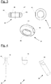
- FIGS. 2a and 2b show the lightning receptor base 32 having two mounting rings 34, 36 and an attachment portion 38 therebetween.
- the two mounting rings 34, 36 are arranged closely adjacent. They each have an outer diameter in the range of 30 mm to 40 mm and have between their outer sides 43 a distance 47 in the range of 5 mm to 20 mm.
- Each of the two attachment rings 34, 36 has an M20 internal thread 40.
- the two attachment rings 34, 36 are arranged side by side. As in Fig. 2b can clearly be seen, but they are not exactly in a plane, but are tilted relative to each other at an angle of about 15 °. All outer edges 42, in particular at the outer peripheries of the fastening rings 34, 36, are rounded with a radius of about 4 mm.
- the lightning receptor base 32 is joined by welding the two fastening rings 34, 36 with the fastening section 38 arranged between the two fastening rings 34, 36.
- Fig. 3 shows a mounting ring 34 of the lightning receptor base 32 top left in cross section, top right in a plan view from above and below in a perspective view. It can be seen particularly in the cross-sectional view well rounded edges 42 at the outer peripheries and a lateral flattening 44 on the outer side 43, which forms a contact surface for welding to the attachment portion 38.
- Fig. 4 shows the mounting portion 38 in two plan views from different directions and additionally in a perspective view.
- the attachment portion 38 has a circular cylindrical basic shape with a diameter in the range of 10 mm to 20 mm.
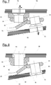
- FIG. 3 shows schematically how the lightning receptor base 32 is attached to the inside 48 of a rotor blade half shell 50.
- the two mounting rings 34, 36 of the lightning receptor base 32 In the lower part of the figure can be seen the two mounting rings 34, 36 of the lightning receptor base 32.
- a first screw 52 is screwed, namely a countersunk screw.
- a mounting plate 54 With this countersunk screw, a mounting plate 54, which consists in the example of a glass fiber composite material, bolted to the lightning receptor base 32.
- the top of the countersunk head of the first screw 52 which has a hexagon socket 56, terminates approximately flush with the top of the mounting plate 54.
- the attachment plate 54 is attached to the inside 48 of the rotor blade half shell 50 with adhesive 58.
- the top of the screw 52 is thus located in the immediate vicinity of the inside 48, so that the screw 52 is particularly visible from the outside.
- Fig. 6 shows another view of the lightning receptor base 32, in which the two mounting rings 34, 36 and in addition the attachment portion 38 can be seen.
- the mounting plate 54 via the first screw 52 bolted to lightning receptor base 32; and the mounting plate 54 is bonded to the inside 48 of the rotor blade half shell 50.
- a second screw 60 is screwed.
- the rotor blade half shell 50 was assembled with another rotor blade half shell 62, so that the lightning receptor base 32 is disposed completely inside the wind turbine rotor blade 10.
- the second screw 60 is also a countersunk screw. It is screwed so far into the fastening ring 36 that its head has a distance of less than 10 mm from the inside 64 of the further rotor blade half shell 62.
- the longitudinal axes 66, 68 of the two screws which correspond to the longitudinal axes of the two threaded bores of the fastening rings 34, 36 are in the Fig. 6 drawn in dash-dotted lines. It can be seen that the longitudinal axis 66 is arranged perpendicular to the rotor blade half shell 50 and the other longitudinal axis 68 perpendicular to the further rotor blade half shell 62.
- the two screws 52, 60 visible through the walls of the rotor blade half shells 50, 62 from the outside, so that their position can be identified by optical means.
- the diameter of the holes 70, 72 is selected to be slightly larger than the diameter of the heads of the screws 52, 60, so that they can be easily unscrewed from the mounting rings 34, 36 and through the holes 70, 72 can be removed through.
- the two lightning receptors 28, 30 are screwed through the bores 70, 72 into the internal threads 49 of the fastening rings 34, 36, as in FIG Fig. 8 shown.
- the lightning receptors 28, 30 are designed as countersunk screws Executed stainless steel and so far screwed into the internal thread 40 of the mounting rings 34, 36 that their faces flush with the outer sides of the rotor blade half shells 50, 62.
- the gaps remaining between the bores 70, 72 and the lightning receptors 28, 30 are filled with a permanently elastic compound.
Claims (13)
- Pale de rotor d'éolienne (10) avec une base de pale (14), un parafoudre (20) destiné à dériver un courant de foudre vers la base de pale (14), un côté aspiration (18), un côté pression (16), un récepteur de foudre (30) disposé sur le côté aspiration (18), un récepteur de foudre (28) disposé sur le côté pression (16) et une base de récepteur de foudre (32) conçue d'un seul tenant, disposée dans la pale de rotor d'éolienne (10), à laquelle sont fixés les deux récepteurs de foudre (28, 30) et le parafoudre (20), caractérisée en ce que la base de récepteur de foudre (32) comporte deux anneaux de fixation (34, 36) présentant respectivement un filet intérieur (40) dans lequel est vissé l'un des deux récepteurs de foudre (28, 30), et présentant un diamètre extérieur et un côté extérieur (43), les côtés extérieurs (43) des anneaux de fixation étant disposés à une distance (47) inférieure à un diamètre extérieur l'un de l'autre.
- Pale de rotor d'éolienne (10) selon la revendication 1, caractérisée en ce qu'un rayon d'arête au niveau des pourtours extérieurs des deux anneaux de fixation (34, 36) mesure 3 mm ou plus.
- Pale de rotor d'éolienne (10) selon la revendication 1 ou 2, caractérisée en ce que les deux anneaux de fixation (34, 36) sont disposés côte à côte latéralement.
- Pale de rotor d'éolienne (10) selon l'une des revendications 1 à 3, caractérisée en ce que les deux anneaux de fixation (34, 36) présentent respectivement un axe longitudinal (66, 68) et les deux axes longitudinaux (66, 68) sont disposés de manière à former un angle compris entre 0° et 30° l'un par rapport à l'autre, de telle façon que l'un des axes longitudinaux (66) coupe perpendiculairement le côté aspiration (18) et l'autre des axes longitudinaux (68) coupe perpendiculairement le côté pression (16).
- Pale de rotor d'éolienne (10) selon l'une des revendications 1 à 4, caractérisée en ce que la base de récepteur de foudre (32) présente une section de fixation (38) reliée au parafoudre (20) et disposée entre les deux anneaux de fixation (34, 36).
- Pale de rotor d'éolienne (10) selon l'une des revendications 1 à 5, caractérisée en ce que les deux anneaux de fixation (34, 36) sont soudés l'un à l'autre et/ou à la section de fixation (38).
- Pale de rotor d'éolienne (10) selon l'une des revendications 1 à 6, caractérisée en ce que chacun des deux anneaux de fixation (34, 36) présente un diamètre extérieur inférieur à celui du récepteur de foudre (28, 30) correspondant.
- Procédé pour la fabrication d'une pale de rotor d'éolienne (10), comprenant les étapes suivantes :• mise à disposition de deux demi-coquilles de pale de rotor (50, 62),• mise à disposition d'une base de récepteur de foudre (32) monobloc, laquelle présente un premier anneau de fixation (34) avec un premier filet intérieur (40) et un deuxième anneau de fixation (36) avec un deuxième filet intérieur (40),• vissage d'une première vis (52) dans le premier filet intérieur (40) et d'une deuxième vis (60) dans le deuxième filet intérieur (40),• fixation de la base de récepteur de foudre (32) sur un côté intérieur (48) de l'une des demi-coquilles de pale de rotor (50, 62),• assemblage des deux demi-coquilles de pale de rotor (50, 62),• réalisation d'un premier perçage (70) à travers une paroi de l'une des demi-coquilles de pale de rotor (50, 62) dans la région de la première vis (52) et d'un deuxième perçage (72) à travers une paroi de l'autre demi-coquille de pale de rotor (62) dans la région de la deuxième vis (60),• retrait des deux vis (52, 60) à travers le perçage (70, 72) respectif,• vissage d'un premier récepteur de foudre (28) à travers le premier perçage (70) dans le premier filet intérieur (40) et d'un deuxième récepteur de foudre (30) à travers le deuxième perçage (72) dans le deuxième filet intérieur (40).
- Procédé selon la revendication 8, caractérisé par l'étape supplémentaire suivante :• identification de la position de l'une des deux vis (52, 60) par voie optique depuis un côté extérieur des demi-coquilles de pale de rotor (50, 62) assemblées.
- Procédé selon la revendication 8 ou 9, caractérisé en ce que les récepteurs de foudre (28, 30) vissés dans les filets intérieurs (40) se terminent à fleur avec un côté extérieur de la demi-coquille de pale de rotor (50, 62) correspondante, sans toucher le perçage (70, 72) qui les entoure.
- Procédé selon la revendication 10, caractérisé par l'étape supplémentaire suivante :• fermeture de la fente entre les récepteurs de foudre (28, 30) et les perçages (70, 72) qui les entourent, après le vissage des deux récepteurs de foudre (28, 30).
- Procédé selon l'une des revendications 8 à 11, caractérisé en ce que les vis (52, 60) sont vissées dans la base de récepteur (32) au point que les têtes des vis (52, 60) sont disposées respectivement à une distance de moins de 10 mm du côté intérieur (48) de l'une des demi-coquilles de pale de rotor (50) après l'assemblage des deux demi-coquilles de pale de rotor (50, 62).
- Procédé selon l'une des revendications 8 à 12, caractérisé en ce qu'une plaque de fixation (54) est fixée à la base de récepteur de foudre (32) à l'aide de l'une des vis (52, 60), et en ce que pour fixer la base de récepteur de foudre (32) au côté intérieur (48) de l'une des demi-coquilles de pale de rotor (50, 62), la plaque de fixation (54) est collée avec le côté intérieur (48) de la demi-coquille de pale de rotor (50, 62).
Priority Applications (4)
| Application Number | Priority Date | Filing Date | Title |
|---|---|---|---|
| EP14164232.2A EP2930357B1 (fr) | 2014-04-10 | 2014-04-10 | Pale de rotor d'éolienne dotée d'un récepteur de foudre |
| ES14164232.2T ES2686707T3 (es) | 2014-04-10 | 2014-04-10 | Pala de rotor de turbina eólica con una base de receptor de rayos |
| DK14164232.2T DK2930357T3 (en) | 2014-04-10 | 2014-04-10 | Rotor blade for wind energy systems and with a lightning conductor base |
| US14/680,964 US10199816B2 (en) | 2014-04-10 | 2015-04-07 | Wind turbine rotor blade having a lightning receptor base and method for making the same |
Applications Claiming Priority (1)
| Application Number | Priority Date | Filing Date | Title |
|---|---|---|---|
| EP14164232.2A EP2930357B1 (fr) | 2014-04-10 | 2014-04-10 | Pale de rotor d'éolienne dotée d'un récepteur de foudre |
Publications (2)
| Publication Number | Publication Date |
|---|---|
| EP2930357A1 EP2930357A1 (fr) | 2015-10-14 |
| EP2930357B1 true EP2930357B1 (fr) | 2018-06-27 |
Family
ID=50478279
Family Applications (1)
| Application Number | Title | Priority Date | Filing Date |
|---|---|---|---|
| EP14164232.2A Active EP2930357B1 (fr) | 2014-04-10 | 2014-04-10 | Pale de rotor d'éolienne dotée d'un récepteur de foudre |
Country Status (4)
| Country | Link |
|---|---|
| US (1) | US10199816B2 (fr) |
| EP (1) | EP2930357B1 (fr) |
| DK (1) | DK2930357T3 (fr) |
| ES (1) | ES2686707T3 (fr) |
Families Citing this family (10)
| Publication number | Priority date | Publication date | Assignee | Title |
|---|---|---|---|---|
| ES2589185B1 (es) * | 2015-05-08 | 2017-09-18 | Gamesa Innovation & Technology, S.L. | Sistema pararrayos para palas de aerogeneradores con componentes estructurales conductores |
| US10344743B2 (en) | 2016-05-13 | 2019-07-09 | Erico International Corporation | Lightning protection system and method for wind turbine blades |
| USD803163S1 (en) | 2016-05-13 | 2017-11-21 | Erico International Corporation | Tip receptor mount for lightning protection systems |
| DE102016116144A1 (de) | 2016-08-30 | 2018-03-01 | Nordex Energy Gmbh | Blitzschutzeinrichtung für ein Windenergieanlagenrotorblatt |
| DK3339632T3 (da) * | 2016-12-22 | 2021-05-25 | Nordex Energy Se & Co Kg | Tilslutnings- og fastgørelsesenhed for en lynreceptor til integration i et vindturbine-rotorblad |
| EP3339633B1 (fr) | 2016-12-22 | 2020-11-25 | Nordex Energy GmbH | Procédé de fabrication d'une liaison équipotentielle sur une pale de rotor d'éolienne |
| EP3869035B1 (fr) | 2020-02-21 | 2022-11-30 | Siemens Gamesa Renewable Energy Innovation & Technology, S.L. | Pale pour un rotor d'éolienne et son procédé de fabrication |
| CN112483335B (zh) * | 2020-11-20 | 2024-04-12 | 江苏双瑞风电叶片有限公司 | 一种风电叶片根部用防雷组件及其安装方法 |
| CN113323822A (zh) * | 2021-07-16 | 2021-08-31 | 上海风雷盾科技有限公司 | 一种风电叶片的防雷装置 |
| CN114109745A (zh) * | 2021-11-30 | 2022-03-01 | 中复连众(酒泉)复合材料有限公司 | 一种兆瓦级风电叶片防雷系统快速连接机构 |
Family Cites Families (13)
| Publication number | Priority date | Publication date | Assignee | Title |
|---|---|---|---|---|
| DK176298B1 (da) * | 2003-09-15 | 2007-06-18 | Lm Glasfiber As | Metode til lynsikring af en vinge til et vindenergianlæg, en lynsikret vinge samt et vindenergianlæg med en sådan vinge |
| DE102005047959B4 (de) * | 2005-10-06 | 2008-01-31 | Nordex Energy Gmbh | Verfahren zur Herstellung einer Durchführung in einem Faserverbundwerkstoff sowie Rotorblatt für eine Windenergieanlage mit einer Durchführung |
| JP4969098B2 (ja) | 2005-12-21 | 2012-07-04 | 三菱重工業株式会社 | 風車翼の落雷保護装置、該落雷保護装置の組立方法、該落雷保護装置を備える風車翼、及び該風車翼を備える風車 |
| DK200600653A (da) | 2006-05-09 | 2007-11-10 | Vestas Wind Sys As | Lynbeskyttelsesanlæg til en vindmöllevinge, og fremgangsmåde til fremstilling af en vindmöllevinge med et lynbeskyttelsessystem |
| US7883321B2 (en) | 2007-02-19 | 2011-02-08 | Vestas Wind Systems A/S | Wind turbine rotor blade and method of manufacturing such rotor blade |
| EP2110552B2 (fr) * | 2008-04-15 | 2018-12-26 | Siemens Aktiengesellschaft | Pale d'éolienne avec un conducteur d'éclairage intégré et son procédé de fabrication |
| KR20100115139A (ko) * | 2009-04-17 | 2010-10-27 | 유니슨 주식회사 | 풍력발전기의 낙뢰 보호 장치 |
| WO2011080177A1 (fr) | 2009-12-28 | 2011-07-07 | Vestas Wind Systems A/S | Protection contre la foudre d'une pale d'éolienne |
| BR112013001639A2 (pt) * | 2010-07-23 | 2016-05-24 | Erico Int Corp | receptor para proteção contra descargas elétricas atmosféricas na pá de turbina eólica |
| EP2420852B1 (fr) * | 2010-08-20 | 2019-11-13 | Siemens Gamesa Renewable Energy A/S | Système de mesure pour conducteur descendant d'une pale d'éolienne |
| JP5546624B2 (ja) * | 2011-12-09 | 2014-07-09 | 三菱重工業株式会社 | 風車翼 |
| CN202628403U (zh) * | 2012-04-11 | 2012-12-26 | 连云港中复连众复合材料集团有限公司 | 一种风机叶片整体防雷装置 |
| GB2519333A (en) * | 2013-10-17 | 2015-04-22 | Vestas Wind Sys As | Improvements relating to lightning protection systems for wind turbine blades |
-
2014
- 2014-04-10 EP EP14164232.2A patent/EP2930357B1/fr active Active
- 2014-04-10 ES ES14164232.2T patent/ES2686707T3/es active Active
- 2014-04-10 DK DK14164232.2T patent/DK2930357T3/en active
-
2015
- 2015-04-07 US US14/680,964 patent/US10199816B2/en not_active Expired - Fee Related
Non-Patent Citations (1)
| Title |
|---|
| None * |
Also Published As
| Publication number | Publication date |
|---|---|
| EP2930357A1 (fr) | 2015-10-14 |
| ES2686707T3 (es) | 2018-10-19 |
| US20150292487A1 (en) | 2015-10-15 |
| DK2930357T3 (en) | 2018-10-01 |
| US10199816B2 (en) | 2019-02-05 |
Similar Documents
| Publication | Publication Date | Title |
|---|---|---|
| EP2930357B1 (fr) | Pale de rotor d'éolienne dotée d'un récepteur de foudre | |
| EP2930010B1 (fr) | Bande pour une pale de rotor d'éoliennes | |
| EP2930352B1 (fr) | Pale de rotor d'éolienne dotée d'un dispositif d'équipotentialité | |
| EP2018475B1 (fr) | Pale de rotor pour une éolienne | |
| EP3339633B1 (fr) | Procédé de fabrication d'une liaison équipotentielle sur une pale de rotor d'éolienne | |
| EP1772621A2 (fr) | Méthode de fabrication d'un trou traversant un matériau composite renforcé par des fibres et pale d'éolienne avec ce trou | |
| WO2009132612A1 (fr) | Procédé de fabrication d'un raccord de pale de rotor, raccord de pale et élément de fixation pour un raccord de pale | |
| EP2182203A2 (fr) | Pale d'éolienne comprenant une extension | |
| EP2740583B1 (fr) | Procédé de fabrication d'une pale de rotor d'éolienne avec un premier et un deuxième segment de pale et pale de rotor d'éolienne | |
| EP2434143B1 (fr) | Pale de rotor ou segment d'une pale de rotor pour une éolienne | |
| EP3129644B1 (fr) | Pale de rotor d'une éolienne | |
| EP3057774B1 (fr) | Pièce munie d'une partie fixation permettant un assemblage par vis et pièce moulée et élément de fixation | |
| EP3339632B1 (fr) | Unité de raccordement et de fixation pour un récepteur d'éclairs à intégrer dans une pale de rotor d'éolienne | |
| EP2675030B1 (fr) | Composant de structure pour une pale de rotor d'éolienne avec un conducteur de paratonnerre | |
| EP3019744B1 (fr) | Pale de rotor avec paratonnerre | |
| EP3204633B1 (fr) | Pale de rotor d'éolienne | |
| EP3482918B1 (fr) | Procédé de fabrication d'une entretoise d'une pale de rotor d'une éolienne | |
| EP2930358B1 (fr) | Pale de rotor d'éolienne dotée d'un élément de compensation de potential | |
| EP3524412A1 (fr) | Pale de rotor d'éolienne divisible dotée d'un dispositif de protection contre la foudre et procédé de fabrication d'une telle pale de rotor d'éolienne | |
| EP3425195A1 (fr) | Pale de rotor d'éolienne divisible comprenant un module de douilles | |
| DE102017107859A1 (de) | Blitzschutzeinrichtung für ein Rotorblatt einer Windenergieanlage | |
| EP2090704A2 (fr) | Dispositif d'ancrage | |
| DE102016116144A1 (de) | Blitzschutzeinrichtung für ein Windenergieanlagenrotorblatt | |
| EP3580052B1 (fr) | Élément de liaison pour relier un élément structural à une structure composite renforcée par fibres | |
| DE102018113504B4 (de) | Vorrichtung mit einem Sandwichbauteil |
Legal Events
| Date | Code | Title | Description |
|---|---|---|---|
| PUAI | Public reference made under article 153(3) epc to a published international application that has entered the european phase |
Free format text: ORIGINAL CODE: 0009012 |
|
| AK | Designated contracting states |
Kind code of ref document: A1 Designated state(s): AL AT BE BG CH CY CZ DE DK EE ES FI FR GB GR HR HU IE IS IT LI LT LU LV MC MK MT NL NO PL PT RO RS SE SI SK SM TR |
|
| AX | Request for extension of the european patent |
Extension state: BA ME |
|
| 17P | Request for examination filed |
Effective date: 20160407 |
|
| RBV | Designated contracting states (corrected) |
Designated state(s): AL AT BE BG CH CY CZ DE DK EE ES FI FR GB GR HR HU IE IS IT LI LT LU LV MC MK MT NL NO PL PT RO RS SE SI SK SM TR |
|
| REG | Reference to a national code |
Ref country code: DE Ref legal event code: R079 Ref document number: 502014008634 Country of ref document: DE Free format text: PREVIOUS MAIN CLASS: F03D0011000000 Ipc: F03D0080300000 |
|
| GRAP | Despatch of communication of intention to grant a patent |
Free format text: ORIGINAL CODE: EPIDOSNIGR1 |
|
| STAA | Information on the status of an ep patent application or granted ep patent |
Free format text: STATUS: GRANT OF PATENT IS INTENDED |
|
| RIC1 | Information provided on ipc code assigned before grant |
Ipc: F03D 1/06 20060101ALI20180115BHEP Ipc: F03D 80/30 20160101AFI20180115BHEP |
|
| RIC1 | Information provided on ipc code assigned before grant |
Ipc: H02G 13/00 20060101ALI20180126BHEP Ipc: F03D 1/06 20060101ALI20180126BHEP Ipc: F03D 80/30 20160101AFI20180126BHEP |
|
| INTG | Intention to grant announced |
Effective date: 20180212 |
|
| GRAS | Grant fee paid |
Free format text: ORIGINAL CODE: EPIDOSNIGR3 |
|
| GRAA | (expected) grant |
Free format text: ORIGINAL CODE: 0009210 |
|
| STAA | Information on the status of an ep patent application or granted ep patent |
Free format text: STATUS: THE PATENT HAS BEEN GRANTED |
|
| AK | Designated contracting states |
Kind code of ref document: B1 Designated state(s): AL AT BE BG CH CY CZ DE DK EE ES FI FR GB GR HR HU IE IS IT LI LT LU LV MC MK MT NL NO PL PT RO RS SE SI SK SM TR |
|
| REG | Reference to a national code |
Ref country code: GB Ref legal event code: FG4D Free format text: NOT ENGLISH |
|
| REG | Reference to a national code |
Ref country code: AT Ref legal event code: REF Ref document number: 1012581 Country of ref document: AT Kind code of ref document: T Effective date: 20180715 |
|
| REG | Reference to a national code |
Ref country code: IE Ref legal event code: FG4D Free format text: LANGUAGE OF EP DOCUMENT: GERMAN |
|
| REG | Reference to a national code |
Ref country code: DE Ref legal event code: R096 Ref document number: 502014008634 Country of ref document: DE |
|
| REG | Reference to a national code |
Ref country code: DK Ref legal event code: T3 Effective date: 20180927 |
|
| REG | Reference to a national code |
Ref country code: ES Ref legal event code: FG2A Ref document number: 2686707 Country of ref document: ES Kind code of ref document: T3 Effective date: 20181019 |
|
| PG25 | Lapsed in a contracting state [announced via postgrant information from national office to epo] |
Ref country code: LT Free format text: LAPSE BECAUSE OF FAILURE TO SUBMIT A TRANSLATION OF THE DESCRIPTION OR TO PAY THE FEE WITHIN THE PRESCRIBED TIME-LIMIT Effective date: 20180627 Ref country code: BG Free format text: LAPSE BECAUSE OF FAILURE TO SUBMIT A TRANSLATION OF THE DESCRIPTION OR TO PAY THE FEE WITHIN THE PRESCRIBED TIME-LIMIT Effective date: 20180927 Ref country code: FI Free format text: LAPSE BECAUSE OF FAILURE TO SUBMIT A TRANSLATION OF THE DESCRIPTION OR TO PAY THE FEE WITHIN THE PRESCRIBED TIME-LIMIT Effective date: 20180627 Ref country code: NO Free format text: LAPSE BECAUSE OF FAILURE TO SUBMIT A TRANSLATION OF THE DESCRIPTION OR TO PAY THE FEE WITHIN THE PRESCRIBED TIME-LIMIT Effective date: 20180927 Ref country code: SE Free format text: LAPSE BECAUSE OF FAILURE TO SUBMIT A TRANSLATION OF THE DESCRIPTION OR TO PAY THE FEE WITHIN THE PRESCRIBED TIME-LIMIT Effective date: 20180627 |
|
| REG | Reference to a national code |
Ref country code: NL Ref legal event code: MP Effective date: 20180627 |
|
| REG | Reference to a national code |
Ref country code: LT Ref legal event code: MG4D |
|
| PG25 | Lapsed in a contracting state [announced via postgrant information from national office to epo] |
Ref country code: GR Free format text: LAPSE BECAUSE OF FAILURE TO SUBMIT A TRANSLATION OF THE DESCRIPTION OR TO PAY THE FEE WITHIN THE PRESCRIBED TIME-LIMIT Effective date: 20180928 Ref country code: HR Free format text: LAPSE BECAUSE OF FAILURE TO SUBMIT A TRANSLATION OF THE DESCRIPTION OR TO PAY THE FEE WITHIN THE PRESCRIBED TIME-LIMIT Effective date: 20180627 Ref country code: LV Free format text: LAPSE BECAUSE OF FAILURE TO SUBMIT A TRANSLATION OF THE DESCRIPTION OR TO PAY THE FEE WITHIN THE PRESCRIBED TIME-LIMIT Effective date: 20180627 Ref country code: RS Free format text: LAPSE BECAUSE OF FAILURE TO SUBMIT A TRANSLATION OF THE DESCRIPTION OR TO PAY THE FEE WITHIN THE PRESCRIBED TIME-LIMIT Effective date: 20180627 |
|
| PG25 | Lapsed in a contracting state [announced via postgrant information from national office to epo] |
Ref country code: NL Free format text: LAPSE BECAUSE OF FAILURE TO SUBMIT A TRANSLATION OF THE DESCRIPTION OR TO PAY THE FEE WITHIN THE PRESCRIBED TIME-LIMIT Effective date: 20180627 |
|
| PG25 | Lapsed in a contracting state [announced via postgrant information from national office to epo] |
Ref country code: RO Free format text: LAPSE BECAUSE OF FAILURE TO SUBMIT A TRANSLATION OF THE DESCRIPTION OR TO PAY THE FEE WITHIN THE PRESCRIBED TIME-LIMIT Effective date: 20180627 Ref country code: SK Free format text: LAPSE BECAUSE OF FAILURE TO SUBMIT A TRANSLATION OF THE DESCRIPTION OR TO PAY THE FEE WITHIN THE PRESCRIBED TIME-LIMIT Effective date: 20180627 Ref country code: CZ Free format text: LAPSE BECAUSE OF FAILURE TO SUBMIT A TRANSLATION OF THE DESCRIPTION OR TO PAY THE FEE WITHIN THE PRESCRIBED TIME-LIMIT Effective date: 20180627 Ref country code: PL Free format text: LAPSE BECAUSE OF FAILURE TO SUBMIT A TRANSLATION OF THE DESCRIPTION OR TO PAY THE FEE WITHIN THE PRESCRIBED TIME-LIMIT Effective date: 20180627 Ref country code: IS Free format text: LAPSE BECAUSE OF FAILURE TO SUBMIT A TRANSLATION OF THE DESCRIPTION OR TO PAY THE FEE WITHIN THE PRESCRIBED TIME-LIMIT Effective date: 20181027 Ref country code: EE Free format text: LAPSE BECAUSE OF FAILURE TO SUBMIT A TRANSLATION OF THE DESCRIPTION OR TO PAY THE FEE WITHIN THE PRESCRIBED TIME-LIMIT Effective date: 20180627 |
|
| REG | Reference to a national code |
Ref country code: CH Ref legal event code: PK Free format text: BERICHTIGUNGEN |
|
| RIC2 | Information provided on ipc code assigned after grant |
Ipc: F03D 1/06 20060101ALI20180126BHEP Ipc: F03D 80/30 20160101AFI20180126BHEP Ipc: H02G 13/00 20060101ALI20180126BHEP |
|
| PG25 | Lapsed in a contracting state [announced via postgrant information from national office to epo] |
Ref country code: IT Free format text: LAPSE BECAUSE OF FAILURE TO SUBMIT A TRANSLATION OF THE DESCRIPTION OR TO PAY THE FEE WITHIN THE PRESCRIBED TIME-LIMIT Effective date: 20180627 Ref country code: SM Free format text: LAPSE BECAUSE OF FAILURE TO SUBMIT A TRANSLATION OF THE DESCRIPTION OR TO PAY THE FEE WITHIN THE PRESCRIBED TIME-LIMIT Effective date: 20180627 |
|
| REG | Reference to a national code |
Ref country code: DE Ref legal event code: R097 Ref document number: 502014008634 Country of ref document: DE |
|
| PLBE | No opposition filed within time limit |
Free format text: ORIGINAL CODE: 0009261 |
|
| STAA | Information on the status of an ep patent application or granted ep patent |
Free format text: STATUS: NO OPPOSITION FILED WITHIN TIME LIMIT |
|
| 26N | No opposition filed |
Effective date: 20190328 |
|
| PG25 | Lapsed in a contracting state [announced via postgrant information from national office to epo] |
Ref country code: SI Free format text: LAPSE BECAUSE OF FAILURE TO SUBMIT A TRANSLATION OF THE DESCRIPTION OR TO PAY THE FEE WITHIN THE PRESCRIBED TIME-LIMIT Effective date: 20180627 |
|
| PG25 | Lapsed in a contracting state [announced via postgrant information from national office to epo] |
Ref country code: AL Free format text: LAPSE BECAUSE OF FAILURE TO SUBMIT A TRANSLATION OF THE DESCRIPTION OR TO PAY THE FEE WITHIN THE PRESCRIBED TIME-LIMIT Effective date: 20180627 |
|
| REG | Reference to a national code |
Ref country code: CH Ref legal event code: PL |
|
| REG | Reference to a national code |
Ref country code: BE Ref legal event code: MM Effective date: 20190430 |
|
| GBPC | Gb: european patent ceased through non-payment of renewal fee |
Effective date: 20190410 |
|
| PG25 | Lapsed in a contracting state [announced via postgrant information from national office to epo] |
Ref country code: LU Free format text: LAPSE BECAUSE OF NON-PAYMENT OF DUE FEES Effective date: 20190410 Ref country code: MC Free format text: LAPSE BECAUSE OF FAILURE TO SUBMIT A TRANSLATION OF THE DESCRIPTION OR TO PAY THE FEE WITHIN THE PRESCRIBED TIME-LIMIT Effective date: 20180627 |
|
| PG25 | Lapsed in a contracting state [announced via postgrant information from national office to epo] |
Ref country code: CH Free format text: LAPSE BECAUSE OF NON-PAYMENT OF DUE FEES Effective date: 20190430 Ref country code: LI Free format text: LAPSE BECAUSE OF NON-PAYMENT OF DUE FEES Effective date: 20190430 Ref country code: GB Free format text: LAPSE BECAUSE OF NON-PAYMENT OF DUE FEES Effective date: 20190410 |
|
| PG25 | Lapsed in a contracting state [announced via postgrant information from national office to epo] |
Ref country code: FR Free format text: LAPSE BECAUSE OF NON-PAYMENT OF DUE FEES Effective date: 20190430 Ref country code: BE Free format text: LAPSE BECAUSE OF NON-PAYMENT OF DUE FEES Effective date: 20190430 |
|
| PG25 | Lapsed in a contracting state [announced via postgrant information from national office to epo] |
Ref country code: TR Free format text: LAPSE BECAUSE OF FAILURE TO SUBMIT A TRANSLATION OF THE DESCRIPTION OR TO PAY THE FEE WITHIN THE PRESCRIBED TIME-LIMIT Effective date: 20180627 |
|
| PG25 | Lapsed in a contracting state [announced via postgrant information from national office to epo] |
Ref country code: IE Free format text: LAPSE BECAUSE OF NON-PAYMENT OF DUE FEES Effective date: 20190410 |
|
| PG25 | Lapsed in a contracting state [announced via postgrant information from national office to epo] |
Ref country code: PT Free format text: LAPSE BECAUSE OF FAILURE TO SUBMIT A TRANSLATION OF THE DESCRIPTION OR TO PAY THE FEE WITHIN THE PRESCRIBED TIME-LIMIT Effective date: 20181029 |
|
| REG | Reference to a national code |
Ref country code: AT Ref legal event code: MM01 Ref document number: 1012581 Country of ref document: AT Kind code of ref document: T Effective date: 20190410 |
|
| PG25 | Lapsed in a contracting state [announced via postgrant information from national office to epo] |
Ref country code: AT Free format text: LAPSE BECAUSE OF NON-PAYMENT OF DUE FEES Effective date: 20190410 |
|
| REG | Reference to a national code |
Ref country code: DE Ref legal event code: R082 Ref document number: 502014008634 Country of ref document: DE Representative=s name: HAUCK PATENTANWALTSPARTNERSCHAFT MBB, DE Ref country code: DE Ref legal event code: R081 Ref document number: 502014008634 Country of ref document: DE Owner name: NORDEX ENERGY SE & CO. KG, DE Free format text: FORMER OWNER: NORDEX ENERGY GMBH, 22419 HAMBURG, DE |
|
| PG25 | Lapsed in a contracting state [announced via postgrant information from national office to epo] |
Ref country code: CY Free format text: LAPSE BECAUSE OF FAILURE TO SUBMIT A TRANSLATION OF THE DESCRIPTION OR TO PAY THE FEE WITHIN THE PRESCRIBED TIME-LIMIT Effective date: 20180627 |
|
| PG25 | Lapsed in a contracting state [announced via postgrant information from national office to epo] |
Ref country code: HU Free format text: LAPSE BECAUSE OF FAILURE TO SUBMIT A TRANSLATION OF THE DESCRIPTION OR TO PAY THE FEE WITHIN THE PRESCRIBED TIME-LIMIT; INVALID AB INITIO Effective date: 20140410 Ref country code: MT Free format text: LAPSE BECAUSE OF FAILURE TO SUBMIT A TRANSLATION OF THE DESCRIPTION OR TO PAY THE FEE WITHIN THE PRESCRIBED TIME-LIMIT Effective date: 20180627 |
|
| PG25 | Lapsed in a contracting state [announced via postgrant information from national office to epo] |
Ref country code: MK Free format text: LAPSE BECAUSE OF FAILURE TO SUBMIT A TRANSLATION OF THE DESCRIPTION OR TO PAY THE FEE WITHIN THE PRESCRIBED TIME-LIMIT Effective date: 20180627 |
|
| P01 | Opt-out of the competence of the unified patent court (upc) registered |
Effective date: 20230602 |
|
| PGFP | Annual fee paid to national office [announced via postgrant information from national office to epo] |
Ref country code: ES Payment date: 20230517 Year of fee payment: 10 Ref country code: DK Payment date: 20230419 Year of fee payment: 10 Ref country code: DE Payment date: 20230418 Year of fee payment: 10 |