EP2930357B1 - Wind turbine rotor blade with a lightning conductor base - Google Patents
Wind turbine rotor blade with a lightning conductor base Download PDFInfo
- Publication number
- EP2930357B1 EP2930357B1 EP14164232.2A EP14164232A EP2930357B1 EP 2930357 B1 EP2930357 B1 EP 2930357B1 EP 14164232 A EP14164232 A EP 14164232A EP 2930357 B1 EP2930357 B1 EP 2930357B1
- Authority
- EP
- European Patent Office
- Prior art keywords
- rotor blade
- lightning
- wind turbine
- turbine rotor
- fastening
- Prior art date
- Legal status (The legal status is an assumption and is not a legal conclusion. Google has not performed a legal analysis and makes no representation as to the accuracy of the status listed.)
- Active
Links
- 239000004020 conductor Substances 0.000 title claims description 22
- 238000000034 method Methods 0.000 claims description 13
- 238000004519 manufacturing process Methods 0.000 claims description 7
- 239000000853 adhesive Substances 0.000 description 5
- 230000001070 adhesive effect Effects 0.000 description 5
- 238000003466 welding Methods 0.000 description 3
- 239000002131 composite material Substances 0.000 description 2
- 150000001875 compounds Chemical class 0.000 description 2
- 238000005304 joining Methods 0.000 description 2
- 229920000049 Carbon (fiber) Polymers 0.000 description 1
- 238000004026 adhesive bonding Methods 0.000 description 1
- 239000004840 adhesive resin Substances 0.000 description 1
- 229920006223 adhesive resin Polymers 0.000 description 1
- 239000004917 carbon fiber Substances 0.000 description 1
- 239000004918 carbon fiber reinforced polymer Substances 0.000 description 1
- 239000011248 coating agent Substances 0.000 description 1
- 238000000576 coating method Methods 0.000 description 1
- 238000010276 construction Methods 0.000 description 1
- 239000000356 contaminant Substances 0.000 description 1
- 238000007599 discharging Methods 0.000 description 1
- 238000005553 drilling Methods 0.000 description 1
- 230000005489 elastic deformation Effects 0.000 description 1
- 239000000835 fiber Substances 0.000 description 1
- 239000011152 fibreglass Substances 0.000 description 1
- 238000005242 forging Methods 0.000 description 1
- 239000003365 glass fiber Substances 0.000 description 1
- 238000010438 heat treatment Methods 0.000 description 1
- 239000002184 metal Substances 0.000 description 1
- VNWKTOKETHGBQD-UHFFFAOYSA-N methane Chemical compound C VNWKTOKETHGBQD-UHFFFAOYSA-N 0.000 description 1
- 230000003287 optical effect Effects 0.000 description 1
- 230000035515 penetration Effects 0.000 description 1
- 238000002360 preparation method Methods 0.000 description 1
- 239000007787 solid Substances 0.000 description 1
- 229910001220 stainless steel Inorganic materials 0.000 description 1
- 239000010935 stainless steel Substances 0.000 description 1
Images


Classifications
-
- F—MECHANICAL ENGINEERING; LIGHTING; HEATING; WEAPONS; BLASTING
- F03—MACHINES OR ENGINES FOR LIQUIDS; WIND, SPRING, OR WEIGHT MOTORS; PRODUCING MECHANICAL POWER OR A REACTIVE PROPULSIVE THRUST, NOT OTHERWISE PROVIDED FOR
- F03D—WIND MOTORS
- F03D1/00—Wind motors with rotation axis substantially parallel to the air flow entering the rotor
- F03D1/06—Rotors
- F03D1/065—Rotors characterised by their construction elements
- F03D1/0675—Rotors characterised by their construction elements of the blades
-
- H—ELECTRICITY
- H02—GENERATION; CONVERSION OR DISTRIBUTION OF ELECTRIC POWER
- H02G—INSTALLATION OF ELECTRIC CABLES OR LINES, OR OF COMBINED OPTICAL AND ELECTRIC CABLES OR LINES
- H02G13/00—Installations of lightning conductors; Fastening thereof to supporting structure
- H02G13/80—Discharge by conduction or dissipation, e.g. rods, arresters, spark gaps
-
- F—MECHANICAL ENGINEERING; LIGHTING; HEATING; WEAPONS; BLASTING
- F03—MACHINES OR ENGINES FOR LIQUIDS; WIND, SPRING, OR WEIGHT MOTORS; PRODUCING MECHANICAL POWER OR A REACTIVE PROPULSIVE THRUST, NOT OTHERWISE PROVIDED FOR
- F03D—WIND MOTORS
- F03D80/00—Details, components or accessories not provided for in groups F03D1/00 - F03D17/00
- F03D80/30—Lightning protection
-
- H—ELECTRICITY
- H02—GENERATION; CONVERSION OR DISTRIBUTION OF ELECTRIC POWER
- H02G—INSTALLATION OF ELECTRIC CABLES OR LINES, OR OF COMBINED OPTICAL AND ELECTRIC CABLES OR LINES
- H02G13/00—Installations of lightning conductors; Fastening thereof to supporting structure
-
- F—MECHANICAL ENGINEERING; LIGHTING; HEATING; WEAPONS; BLASTING
- F05—INDEXING SCHEMES RELATING TO ENGINES OR PUMPS IN VARIOUS SUBCLASSES OF CLASSES F01-F04
- F05B—INDEXING SCHEME RELATING TO WIND, SPRING, WEIGHT, INERTIA OR LIKE MOTORS, TO MACHINES OR ENGINES FOR LIQUIDS COVERED BY SUBCLASSES F03B, F03D AND F03G
- F05B2230/00—Manufacture
- F05B2230/60—Assembly methods
-
- Y—GENERAL TAGGING OF NEW TECHNOLOGICAL DEVELOPMENTS; GENERAL TAGGING OF CROSS-SECTIONAL TECHNOLOGIES SPANNING OVER SEVERAL SECTIONS OF THE IPC; TECHNICAL SUBJECTS COVERED BY FORMER USPC CROSS-REFERENCE ART COLLECTIONS [XRACs] AND DIGESTS
- Y02—TECHNOLOGIES OR APPLICATIONS FOR MITIGATION OR ADAPTATION AGAINST CLIMATE CHANGE
- Y02E—REDUCTION OF GREENHOUSE GAS [GHG] EMISSIONS, RELATED TO ENERGY GENERATION, TRANSMISSION OR DISTRIBUTION
- Y02E10/00—Energy generation through renewable energy sources
- Y02E10/70—Wind energy
- Y02E10/72—Wind turbines with rotation axis in wind direction
-
- Y—GENERAL TAGGING OF NEW TECHNOLOGICAL DEVELOPMENTS; GENERAL TAGGING OF CROSS-SECTIONAL TECHNOLOGIES SPANNING OVER SEVERAL SECTIONS OF THE IPC; TECHNICAL SUBJECTS COVERED BY FORMER USPC CROSS-REFERENCE ART COLLECTIONS [XRACs] AND DIGESTS
- Y02—TECHNOLOGIES OR APPLICATIONS FOR MITIGATION OR ADAPTATION AGAINST CLIMATE CHANGE
- Y02P—CLIMATE CHANGE MITIGATION TECHNOLOGIES IN THE PRODUCTION OR PROCESSING OF GOODS
- Y02P70/00—Climate change mitigation technologies in the production process for final industrial or consumer products
- Y02P70/50—Manufacturing or production processes characterised by the final manufactured product
Definitions
- the invention relates to a wind turbine rotor blade with two lightning receptors, which are arranged on a suction and on a pressure side, and arranged in the wind turbine blade, integrally formed lightning receptor base to which the two lightning receptors and a lightning conductor are attached, and a method for producing such wind turbine rotor blade.
- a lightning protection device It is known to protect wind turbine rotor blades with a lightning protection device from damage caused by a lightning strike.
- a plurality of lightning receptors can be arranged on the rotor blade.
- the current of a lightning strikes in such a lightning receptor is derived via a lightning conductor to the blade root and from there via the gondola and the tower of the wind turbine into the ground.
- the lightning receptors and any other elements of the lightning protection should be placed so that lightning strikes the lightning receptors only. Any lightning strike to another location, be it another electrically conductive element of the wind turbine rotor blade, such as a carbon fiber support structure, electrical heater, or other electrical conduit, may result in irreparable damage to the rotor blade. This also applies to lightning strikes at a distance from a lightning protection receptor in a lightning receptor base or in the lightning conductor itself.
- WO 2008/101506 A2 is a wind turbine rotor blade with two in the area of the blade tip opposite each other arranged lightning receptors known.
- the lightning receptors are each bolted to a lightning receptor base.
- the two receptor bases are connected by a bolt coupled and separated from each other via electrical lines connected to a central lightning conductor.
- WO 2011/080177 A1 a lightning protection device for a wind turbine rotor blade has become known.
- a conductive surface coating serves as a lightning receptor and is electrically coupled via rods to a lightning protection conductor located inside the rotor blade.
- a lightning protection device for a wind turbine rotor blade has become known in which opposing lightning receptors are coupled via a rod to a lightning protection conductor.
- EP 1 965 076 A1 a wind turbine rotor blade has become known in which in the area of the blade tip two arranged on the pressure and suction side lightning receptors are bolted to a one-piece formed Blitzrezeptorbasis.
- the lightning receptor base is a solid, large volume block of electrically conductive material.
- the publication US 2006/0280613 A1 shows a wind turbine rotor blade with multiple lightning receptors. These are each bolted to a metallic connecting element. An additional connector establishes an electrical connection between each two lightning receptors and a lightning conductor.
- the publication US 2007/0081900 A1 shows a wind turbine rotor blade with a substantially box-shaped lightning receptor base.
- Another wind turbine rotor blade is known from CN 202628403 U .
- the wind turbine rotor blade has a blade root, a lightning conductor for discharging a lightning current to the blade root, a suction side, a pressure side, a lightning-side mounted lightning receptor, a pressure-side disposed lightning receptor and a wind turbine rotor blade disposed integrally formed lightning receptor base to which the two lightning receptors and the lightning conductor are attached.
- the flash receptor base includes two mounting rings, each having an internal thread into which one of the two lightning receptors is threaded, and an outside diameter, the outside surfaces of the fastening rings being spaced apart by less than an outside diameter.
- the wind turbine rotor blade may be intended for a wind turbine with a substantially horizontal axis. It can be made of a fiber composite material, in particular of two interconnected half-shells. It may comprise an aerodynamic sheath formed, for example, by the outsides of the two half-shells, and one or more straps, for example of glass fiber or carbon fiber reinforced plastic.
- the two half-shells can be connected to one another via one or more webs, which in particular can be arranged between two mutually opposite main straps.
- the lightning protection conductor can extend substantially over the entire length of the wind turbine rotor blade, in particular from a connection point in the region of the blade root to the region of the blade tip. There he can be connected to the lightning receptor base. The electrical connection between the lightning conductor and the two lightning receptors may be made via the lightning receptor base.
- the two lightning receptors are made of an electrically conductive material, preferably of metal, and are on the outside of the wind turbine rotor blade arranged so that they are approximately flush with the suction side or with the pressure side. They can be arranged opposite each other in the area of the blade tip, but also at a distance from it. It is also possible to provide a plurality of pairs of lightning receptors arranged at different distances from the blade tip, to each of which a lightning receptor base is assigned.
- the lightning receptors and the lightning receptor base may be located in a longitudinal portion or in a region near the trailing edge of the wind turbine rotor blade where the distance between the suction and pressure sides is so small that access to the interior of the rotor blade is not readily possible. For example, the distance may be 30 cm or less or 20 cm or less.
- An essential component of the lightning receptor base according to the invention are the two fastening rings, which are arranged closely adjacent to each other.
- the outer sides of the fastening rings are arranged at a distance of less than an outer diameter of a fastening ring.
- Each mounting ring has an internal thread into which one of the two lightning receptors is screwed.
- the lightning receptor can have a bolt-shaped section with a corresponding external thread.
- the lightning receptors consist of a threaded bolt with, for example, a disk-shaped head.
- a multi-part design of the lightning receptors is possible, for example, with a disc in which a threaded bolt is inserted.
- the threads are dimensioned so that a lightning current of, for example, 200 kA can be derived without damage via the screw connection.
- the lightning receptor base according to the invention has very compact dimensions. At the same time it allows a secure attachment of the two lightning receptors and a damage-free dissipation of the lightning current. Because of its compact shape, it is particularly material-saving. Another advantage is that the Because of its compact form, the lightning receptor base has a very low likelihood of lightning, which significantly reduces the likelihood of lightning strike at a lightning receptor past the receptor base.
- the fastening rings are each closed in a ring around the internal thread around. They can be circular.
- an edge radius at the outer peripheries of the two attachment rings is 3 mm or more. Such strongly rounded edges counteract local field strength maxima and further reduce the attractiveness of the lightning receptor base for a lightning strike.
- the two attachment rings are arranged side by side.
- the height of the entire lightning receptor base may be substantially limited to the length of the internal threads, so that the lightning receptor base also fits in areas of the wind turbine rotor blade with a very small profile thickness.
- the lightning receptors can be screwed deep into the internal threads or screwed through the fastening rings without the studs of the lightning receptors abutting each other.
- the two attachment rings each have a longitudinal axis extending through the center of the attachment ring.
- the two longitudinal axes are arranged at an angle in the range of 0 ° to 30 ° to each other, so that one of the longitudinal axes perpendicular to the suction side and the other of the longitudinal sides of the pressure side.
- the angle can lie in particular in the range of 3 ° to 20 °.
- the shape of the lightning receptor base already dictates the correct angular arrangement of the two lightning receptors with respect to one another, so when mounting the lightning receptor base in the rotor blade in the intended position, the correct arrangement of the two lightning receptors is fixed.
- the lightning receptor base has a mounting portion connected to the lightning conductor and disposed between the two mounting rings.
- the attachment portion may for example be tubular or rod-shaped and welded to the lightning conductor.
- the arrangement of the attachment portion between the two attachment rings contributes to the compact construction of the lightning receptor base.
- the lightning receptor base may consist essentially or exclusively of the two attachment rings and the attachment portion.
- the two attachment rings are welded together and / or with the attachment portion.
- the attachment rings can be made particularly inexpensive, for example as turned parts.
- the lightning receptor base can be made in one piece, for example as a die forging.
- the two attachment rings have a smaller outer diameter than the lightning receptors.
- the lightning receptor base relative to the lightning receptors is once again less attractive for a striking flash.
- the method can be used in particular for producing a wind turbine rotor blade with the features of one of the claims directed thereon.
- the method provides a simple and practical way of producing such a wind turbine rotor blade.
- the one-piece flash receptor base is first attached to an inner side of one of the rotor blade half shells, for example with laminate layers and an adhesive, such as adhesive resin, which are applied in the region of the attachment portion or the lightning protection conductor connected thereto.
- an adhesive such as adhesive resin
- the two screws can serve as an orientation in the preparation of the two holes through the walls of the two half-shells, because their arrangement in the assembled from the two Rotorblatt petitionschalen rotor blade characterizes the position of the two internal threads into which the lightning receptors are screwed.
- the arrangement of the screws can serve as an orientation for the production of the bores through the rotor blade walls.
- the position of the screws can be determined in any way, for example, using magnets.
- sufficiently large screws preferably with a characteristically structured screw head, in particular with a hexagon socket, however, it is in many cases possible to detect the two screws through the rotor blade wall with the naked eye. Making the holes in the right place is therefore particularly easy.
- the lightning receptors screwed into the internal thread terminate flush with an outside of the relevant rotor blade half shell, without touching the bore surrounding it.
- the bore is made large enough to leave clearance around the screwed-in flash receptors.
- the attachment of the lightning receptors takes place exclusively via the lightning receptor base, and a force acting on the lightning receptors, in particular in an elastic deformation of the wind turbine rotor blade does not occur. This contributes to a permanent attachment of the lightning protection device.
- the gaps can be closed with a permanently elastic compound.
- a seal of the interior of the wind turbine blade is achieved without the rotor blade wall forces can be exerted on the lightning protection device.
- the screws are screwed so far into the receptor base that the heads of the screws after joining the two Rotor blade half shells are each arranged at a distance of less than 10 mm from the inside of one of the rotor blade half shells. Preferably, an even smaller distance of, for example, less than 5 mm can be selected.
- one mounting plate is attached to the flash receptor base with one of the screws, and for attaching the lightning receptor base to the inside of one of the rotor blade half shells, the mounting plate is bonded to the inside of the rotor blade half shell.
- the mounting plate allows a simple and relatively large-scale bonding with the rotor blade half shell.
- the lightning receptor base itself can be glued to the inside of the rotor blade half shell or to the mounting plate. A particular advantage is that after fixing the mounting plate on the inside of the rotor blade half shell, a readjustment of the position of the lightning receptor base is still possible, at least by twisting. The lightning receptor base can thus be easily aligned exactly before it is finally fixed.
- the head of the screw used to attach the mounting plate to the lightning receptor base may be recessed into the mounting plate so that it is flush with its surface. It is then after gluing the mounting plate with the rotor blade half shell directly on the inside of the rotor blade shell, so that it is particularly visible from the outside.
- the wind turbine rotor blade 10 off Fig. 1 has a blade tip 12, a blade root 14, a pressure side 16 and a suction side 18.
- a lightning conductor 20 leads from the blade root 14 to the area of the blade tip 12, where it is connected to a blade tip flash receptor 22.
- an electrical heating device 26 is indicated as an additional option.
- a lightning receptor 28 arranged on the pressure side 16.
- another lightning receptor 30 (see FIG Fig. 8 ) about opposite.
- the two lightning receptors 28, 30 are connected to a lightning receptor base 32 located inside the wind turbine rotor blade 10 (see, for example, FIG Fig. 2 ) screwed.
- the lightning receptor base 32 is connected to the lightning conductor 20.
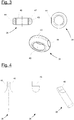
- FIGS. 2a and 2b show the lightning receptor base 32 having two mounting rings 34, 36 and an attachment portion 38 therebetween.
- the two mounting rings 34, 36 are arranged closely adjacent. They each have an outer diameter in the range of 30 mm to 40 mm and have between their outer sides 43 a distance 47 in the range of 5 mm to 20 mm.
- Each of the two attachment rings 34, 36 has an M20 internal thread 40.
- the two attachment rings 34, 36 are arranged side by side. As in Fig. 2b can clearly be seen, but they are not exactly in a plane, but are tilted relative to each other at an angle of about 15 °. All outer edges 42, in particular at the outer peripheries of the fastening rings 34, 36, are rounded with a radius of about 4 mm.
- the lightning receptor base 32 is joined by welding the two fastening rings 34, 36 with the fastening section 38 arranged between the two fastening rings 34, 36.
- Fig. 3 shows a mounting ring 34 of the lightning receptor base 32 top left in cross section, top right in a plan view from above and below in a perspective view. It can be seen particularly in the cross-sectional view well rounded edges 42 at the outer peripheries and a lateral flattening 44 on the outer side 43, which forms a contact surface for welding to the attachment portion 38.
- Fig. 4 shows the mounting portion 38 in two plan views from different directions and additionally in a perspective view.
- the attachment portion 38 has a circular cylindrical basic shape with a diameter in the range of 10 mm to 20 mm.
- FIG. 3 shows schematically how the lightning receptor base 32 is attached to the inside 48 of a rotor blade half shell 50.
- the two mounting rings 34, 36 of the lightning receptor base 32 In the lower part of the figure can be seen the two mounting rings 34, 36 of the lightning receptor base 32.
- a first screw 52 is screwed, namely a countersunk screw.
- a mounting plate 54 With this countersunk screw, a mounting plate 54, which consists in the example of a glass fiber composite material, bolted to the lightning receptor base 32.
- the top of the countersunk head of the first screw 52 which has a hexagon socket 56, terminates approximately flush with the top of the mounting plate 54.
- the attachment plate 54 is attached to the inside 48 of the rotor blade half shell 50 with adhesive 58.
- the top of the screw 52 is thus located in the immediate vicinity of the inside 48, so that the screw 52 is particularly visible from the outside.
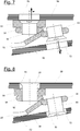
- Fig. 6 shows another view of the lightning receptor base 32, in which the two mounting rings 34, 36 and in addition the attachment portion 38 can be seen.
- the mounting plate 54 via the first screw 52 bolted to lightning receptor base 32; and the mounting plate 54 is bonded to the inside 48 of the rotor blade half shell 50.
- a second screw 60 is screwed.
- the rotor blade half shell 50 was assembled with another rotor blade half shell 62, so that the lightning receptor base 32 is disposed completely inside the wind turbine rotor blade 10.
- the second screw 60 is also a countersunk screw. It is screwed so far into the fastening ring 36 that its head has a distance of less than 10 mm from the inside 64 of the further rotor blade half shell 62.
- the longitudinal axes 66, 68 of the two screws which correspond to the longitudinal axes of the two threaded bores of the fastening rings 34, 36 are in the Fig. 6 drawn in dash-dotted lines. It can be seen that the longitudinal axis 66 is arranged perpendicular to the rotor blade half shell 50 and the other longitudinal axis 68 perpendicular to the further rotor blade half shell 62.
- the two screws 52, 60 visible through the walls of the rotor blade half shells 50, 62 from the outside, so that their position can be identified by optical means.
- the diameter of the holes 70, 72 is selected to be slightly larger than the diameter of the heads of the screws 52, 60, so that they can be easily unscrewed from the mounting rings 34, 36 and through the holes 70, 72 can be removed through.
- the two lightning receptors 28, 30 are screwed through the bores 70, 72 into the internal threads 49 of the fastening rings 34, 36, as in FIG Fig. 8 shown.
- the lightning receptors 28, 30 are designed as countersunk screws Executed stainless steel and so far screwed into the internal thread 40 of the mounting rings 34, 36 that their faces flush with the outer sides of the rotor blade half shells 50, 62.
- the gaps remaining between the bores 70, 72 and the lightning receptors 28, 30 are filled with a permanently elastic compound.
Description
Die Erfindung betrifft ein Windenergieanlagenrotorblatt mit zwei Blitzrezeptoren, die an einer Saug- und an einer Druckseite angeordnet sind, und einer in dem Windenergieanlagenrotorblatt angeordneten, einteilig ausgebildeten Blitzrezeptorbasis, an der die beiden Blitzrezeptoren und ein Blitzschutzleiter befestigt sind, sowie ein Verfahren zur Herstellung eines solchen Windenergieanlagenrotorblatts.The invention relates to a wind turbine rotor blade with two lightning receptors, which are arranged on a suction and on a pressure side, and arranged in the wind turbine blade, integrally formed lightning receptor base to which the two lightning receptors and a lightning conductor are attached, and a method for producing such wind turbine rotor blade.
Es ist bekannt, Windenergieanlagenrotorblätter mit einer Blitzschutzeinrichtung vor Schäden durch einen Blitzschlag zu bewahren. Hierzu können mehrere Blitzrezeptoren am Rotorblatt angeordnet werden. Der Strom eines in einen solchen Blitzrezeptor einschlagenden Blitzes wird über einen Blitzschutzleiter zur Blattwurzel hin und von dort über die Gondel und den Turm der Windenergieanlage in den Erdboden abgeleitet.It is known to protect wind turbine rotor blades with a lightning protection device from damage caused by a lightning strike. For this purpose, a plurality of lightning receptors can be arranged on the rotor blade. The current of a lightning strikes in such a lightning receptor is derived via a lightning conductor to the blade root and from there via the gondola and the tower of the wind turbine into the ground.
Die Blitzrezeptoren und alle weiteren Elemente der Blitzschutzeinrichtung sollten so angeordnet werden, dass Blitze ausschließlich in die Blitzrezeptoren einschlagen. Jeder Blitzschlag an einem anderen Ort, sei es in ein anderes elektrisch leitfähiges Element des Windenergieanlagenrotorblatts wie beispielsweise eine Tragstruktur aus einem Kohlenstofffasermaterial, eine elektrische Heizeinrichtung oder eine sonstige elektrische Leitung, kann unter Umständen zu einer irreparablen Beschädigung des Rotorblatts führen. Dies gilt auch für Blitze, die in einem Abstand von einem Blitzschutzrezeptor in eine Blitzrezeptorbasis oder in den Blitzschutzleiter selbst einschlagen.The lightning receptors and any other elements of the lightning protection should be placed so that lightning strikes the lightning receptors only. Any lightning strike to another location, be it another electrically conductive element of the wind turbine rotor blade, such as a carbon fiber support structure, electrical heater, or other electrical conduit, may result in irreparable damage to the rotor blade. This also applies to lightning strikes at a distance from a lightning protection receptor in a lightning receptor base or in the lightning conductor itself.
Aus der Druckschrift
Aus der Druckschrift
Aus der Druckschrift
Aus der Druckschrift
Die Druckschrift
Die Druckschrift
From the publication
From the publication
From the publication
The publication
The publication
Diese Aufgabe wird gelöst durch das Windenergieanlagenrotorblatt mit den Merkmalen des Anspruchs 1. Vorteilhafte Ausgestaltungen sind in den sich anschließenden Unteransprüchen angegeben.This object is achieved by the wind turbine blade with the features of claim 1. Advantageous embodiments are specified in the subsequent subclaims.
Das Windenergieanlagenrotorblatt hat eine Blattwurzel, einen Blitzschutzleiter zur Ableitung eines Blitzstroms zur Blattwurzel, eine Saugseite, eine Druckseite, einen an der Saugseite angeordneten Blitzrezeptor, einen an der Druckseite angeordneten Blitzrezeptor und eine in dem Windenergieanlagenrotorblatt angeordnete, einteilig ausgebildete Blitzrezeptorbasis, an der die beiden Blitzrezeptoren und der Blitzschutzleiter befestigt sind. Die Blitzrezeptorbasis umfasst zwei Befestigungsringe, die jeweils ein Innengewinde, in das einer der beiden Blitzrezeptoren eingeschraubt ist, und einen Außendurchmesser aufweisen, wobei die Außenseiten der Befestigungsringe die in einem Abstand von weniger als einem Außendurchmesser voneinander angeordnet sind.The wind turbine rotor blade has a blade root, a lightning conductor for discharging a lightning current to the blade root, a suction side, a pressure side, a lightning-side mounted lightning receptor, a pressure-side disposed lightning receptor and a wind turbine rotor blade disposed integrally formed lightning receptor base to which the two lightning receptors and the lightning conductor are attached. The flash receptor base includes two mounting rings, each having an internal thread into which one of the two lightning receptors is threaded, and an outside diameter, the outside surfaces of the fastening rings being spaced apart by less than an outside diameter.
Das Windenergieanlagenrotorblatt kann für eine Windenergieanlage mit im Wesentlichen horizontaler Achse bestimmt sein. Es kann aus einem Faserverbundmaterial hergestellt sein, insbesondere aus zwei miteinander verbundenen Halbschalen. Es kann eine aerodynamische Hülle, die zum Beispiel von den Außenseiten der beiden Halbschalen gebildet ist, sowie einen oder mehrere Gurte aufweisen, beispielsweise aus glasfaser- oder kohlenstofffaserverstärktem Kunststoff. Die beiden Halbschalen können über einen oder mehrere Stege miteinander verbunden sein, die insbesondere zwischen zwei einander gegenüberliegenden Hauptgurten angeordnet sein können.The wind turbine rotor blade may be intended for a wind turbine with a substantially horizontal axis. It can be made of a fiber composite material, in particular of two interconnected half-shells. It may comprise an aerodynamic sheath formed, for example, by the outsides of the two half-shells, and one or more straps, for example of glass fiber or carbon fiber reinforced plastic. The two half-shells can be connected to one another via one or more webs, which in particular can be arranged between two mutually opposite main straps.
Der Blitzschutzleiter kann sich im Wesentlichen über die gesamte Länge des Windenergieanlagenrotorblatts erstrecken, insbesondere von einem Anschlusspunkt im Bereich der Blattwurzel bis in den Bereich der Blattspitze. Dort kann er mit der Blitzrezeptorbasis verbunden sein. Die elektrische Verbindung zwischen dem Blitzschutzleiter und den beiden Blitzrezeptoren kann über die Blitzrezeptorbasis hergestellt sein.The lightning protection conductor can extend substantially over the entire length of the wind turbine rotor blade, in particular from a connection point in the region of the blade root to the region of the blade tip. There he can be connected to the lightning receptor base. The electrical connection between the lightning conductor and the two lightning receptors may be made via the lightning receptor base.
Die beiden Blitzrezeptoren bestehen aus einem elektrisch leitfähigen Material, vorzugsweise aus Metall, und sind an der Außenseite des Windenergieanlagenrotorblatts angeordnet, sodass sie etwa bündig mit der Saugseite bzw. mit der Druckseite abschließen. Sie können einander gegenüberliegend im Bereich der Blattspitze angeordnet sein, aber auch in einem Abstand davon. Es können auch mehrere, in unterschiedlichen Abständen von der Blattspitze angeordnete Paare von Blitzrezeptoren, denen jeweils eine Blitzrezeptorbasis zugeordnet ist, vorgesehen sein. Die Blitzrezeptoren und die Blitzrezeptorbasis können in einem Längsabschnitt oder in einem Bereich nahe der Hinterkante des Windenergieanlagenrotorblatts angeordnet sein, in dem der Abstand zwischen Saug- und Druckseite so gering ist, dass ein Zugang zum Inneren des Rotorblatts nicht ohne weiteres möglich ist. Beispielsweise kann der Abstand 30 cm oder weniger oder 20 cm oder weniger betragen.The two lightning receptors are made of an electrically conductive material, preferably of metal, and are on the outside of the wind turbine rotor blade arranged so that they are approximately flush with the suction side or with the pressure side. They can be arranged opposite each other in the area of the blade tip, but also at a distance from it. It is also possible to provide a plurality of pairs of lightning receptors arranged at different distances from the blade tip, to each of which a lightning receptor base is assigned. The lightning receptors and the lightning receptor base may be located in a longitudinal portion or in a region near the trailing edge of the wind turbine rotor blade where the distance between the suction and pressure sides is so small that access to the interior of the rotor blade is not readily possible. For example, the distance may be 30 cm or less or 20 cm or less.
Wesentlicher Bestandteil der erfindungsgemäßen Blitzrezeptorbasis sind die beiden Befestigungsringe, die eng benachbart zueinander angeordnet sind. Die Außenseiten der Befestigungsringe sind in einem Abstand von weniger als einem Außendurchmesser eines Befestigungsrings angeordnet. Jeder Befestigungsring weist ein Innengewinde auf, in das einer der beiden Blitzrezeptoren eingeschraubt ist. Hierzu kann der Blitzrezeptor einen bolzenförmigen Abschnitt mit einem entsprechenden Außengewinde aufweisen. Im einfachsten Fall bestehen die Blitzrezeptoren aus einem Gewindebolzen mit einem zum Beispiel scheibenförmigen Kopf. Auch eine mehrteilige Ausführung der Blitzrezeptoren ist möglich, beispielsweise mit einer Scheibe, in die ein Gewindebolzen eingesetzt ist. Die Gewinde sind so dimensioniert, dass über die Schraubverbindung ein Blitzstrom von beispielsweise 200 kA beschädigungsfrei abgeleitet werden kann.An essential component of the lightning receptor base according to the invention are the two fastening rings, which are arranged closely adjacent to each other. The outer sides of the fastening rings are arranged at a distance of less than an outer diameter of a fastening ring. Each mounting ring has an internal thread into which one of the two lightning receptors is screwed. For this purpose, the lightning receptor can have a bolt-shaped section with a corresponding external thread. In the simplest case, the lightning receptors consist of a threaded bolt with, for example, a disk-shaped head. A multi-part design of the lightning receptors is possible, for example, with a disc in which a threaded bolt is inserted. The threads are dimensioned so that a lightning current of, for example, 200 kA can be derived without damage via the screw connection.
Die erfindungsgemäße Blitzrezeptorbasis weist sehr kompakte Abmessungen auf. Zugleich ermöglicht sie eine sichere Befestigung der beiden Blitzrezeptoren und eine beschädigungsfreie Ableitung des Blitzstroms. Wegen ihrer kompakten Gestalt ist sie besonders materialsparend. Ein weiterer Vorteil besteht darin, dass die Blitzrezeptorbasis aufgrund ihrer kompakten Form eine sehr geringe Attraktivität für Blitze besitzt, wodurch die Wahrscheinlichkeit eines Blitzschlags an einem Blitzrezeptor vorbei in die Rezeptorbasis wesentlich reduziert wird. Die Befestigungsringe sind jeweils ringförmig um das Innengewinde herum geschlossen. Sie können kreisringförmig sein.The lightning receptor base according to the invention has very compact dimensions. At the same time it allows a secure attachment of the two lightning receptors and a damage-free dissipation of the lightning current. Because of its compact shape, it is particularly material-saving. Another advantage is that the Because of its compact form, the lightning receptor base has a very low likelihood of lightning, which significantly reduces the likelihood of lightning strike at a lightning receptor past the receptor base. The fastening rings are each closed in a ring around the internal thread around. They can be circular.
In einer Ausgestaltung beträgt ein Kantenradius an den Außenumfängen der beiden Befestigungsringe 3 mm oder mehr. Solche stark abgerundeten Kanten wirken lokalen Feldstärkemaxima entgegen und senken die Attraktivität der Blitzrezeptorbasis für einen Blitzschlag zusätzlich.In one embodiment, an edge radius at the outer peripheries of the two attachment rings is 3 mm or more. Such strongly rounded edges counteract local field strength maxima and further reduce the attractiveness of the lightning receptor base for a lightning strike.
In einer Ausgestaltung sind die beiden Befestigungsringe seitlich nebeneinander angeordnet. Bei dieser Anordnung kann die Höhe der gesamten Blitzrezeptorbasis im Wesentlichen auf die Länge der Innengewinde beschränkt sein, sodass die Blitzrezeptorbasis auch in Bereichen des Windenergieanlagenrotorblatts mit sehr geringer Profildicke Platz findet. Außerdem können die Blitzrezeptoren tief in die Innengewinde eingeschraubt bzw. durch die Befestigungsringe hindurch geschraubt werden, ohne dass die Gewindebolzen der Blitzrezeptoren aneinander stoßen.In one embodiment, the two attachment rings are arranged side by side. With this arrangement, the height of the entire lightning receptor base may be substantially limited to the length of the internal threads, so that the lightning receptor base also fits in areas of the wind turbine rotor blade with a very small profile thickness. In addition, the lightning receptors can be screwed deep into the internal threads or screwed through the fastening rings without the studs of the lightning receptors abutting each other.
In einer Ausgestaltung weisen die beiden Befestigungsringe jeweils eine durch den Mittelpunkt des Befestigungsrings verlaufende Längsachse auf. Die beiden Längsachsen sind in einem Winkel im Bereich von 0° bis 30° zueinander angeordnet, sodass eine der Längsachsen die Saugseite und die andere der Längsseiten die Druckseite senkrecht schneidet. Bei einer Anordnung der Blitzrezeptoren zwischen einer Profilendkante und einer Position mit maximaler Profildicke kann der Winkel insbesondere im Bereich von 3° bis 20° liegen. In diesem Fall gibt die Gestalt der Blitzrezeptorbasis bereits die richtige Winkelanordnung der beiden Blitzrezeptoren zueinander vor, sodass bei Befestigung der Blitzrezeptorbasis im Rotorblatt in der vorgesehenen Position die richtige Anordnung der beiden Blitzrezeptoren festgelegt ist.In one embodiment, the two attachment rings each have a longitudinal axis extending through the center of the attachment ring. The two longitudinal axes are arranged at an angle in the range of 0 ° to 30 ° to each other, so that one of the longitudinal axes perpendicular to the suction side and the other of the longitudinal sides of the pressure side. In the case of an arrangement of the lightning receptors between a profile end edge and a position with maximum profile thickness, the angle can lie in particular in the range of 3 ° to 20 °. In this case, the shape of the lightning receptor base already dictates the correct angular arrangement of the two lightning receptors with respect to one another, so when mounting the lightning receptor base in the rotor blade in the intended position, the correct arrangement of the two lightning receptors is fixed.
In einer Ausgestaltung weist die Blitzrezeptorbasis einen Befestigungsabschnitt auf, der mit dem Blitzschutzleiter verbunden und zwischen den beiden Befestigungsringen angeordnet ist. Der Befestigungsabschnitt kann beispielsweise rohr- oder stabförmig und mit dem Blitzschutzleiter verschweißt sein. Die Anordnung des Befestigungsabschnitts zwischen den beiden Befestigungsringen trägt zum kompakten Aufbau der Blitzrezeptorbasis bei. Insbesondere kann die Blitzrezeptorbasis im Wesentlichen oder ausschließlich aus den beiden Befestigungsringen und dem Befestigungsabschnitt bestehen.In one embodiment, the lightning receptor base has a mounting portion connected to the lightning conductor and disposed between the two mounting rings. The attachment portion may for example be tubular or rod-shaped and welded to the lightning conductor. The arrangement of the attachment portion between the two attachment rings contributes to the compact construction of the lightning receptor base. In particular, the lightning receptor base may consist essentially or exclusively of the two attachment rings and the attachment portion.
In einer Ausgestaltung sind die beiden Befestigungsringe miteinander und/oder mit dem Befestigungsabschnitt verschweißt. In diesem Fall können insbesondere die Befestigungsringe besonders kostengünstig gefertigt werden, zum Beispiel als Drehteile. Alternativ kann die Blitzrezeptorbasis einstückig gefertigt werden, zum Beispiel als Gesenkschmiedeteil.In one embodiment, the two attachment rings are welded together and / or with the attachment portion. In this case, in particular, the attachment rings can be made particularly inexpensive, for example as turned parts. Alternatively, the lightning receptor base can be made in one piece, for example as a die forging.
In einer Ausgestaltung weisen die beiden Befestigungsringe einen kleineren Außendurchmesser auf als die Blitzrezeptoren. Dadurch ist die Blitzrezeptorbasis relativ zu den Blitzrezeptoren nochmals weniger attraktiv für einen einschlagenden Blitz.In one embodiment, the two attachment rings have a smaller outer diameter than the lightning receptors. As a result, the lightning receptor base relative to the lightning receptors is once again less attractive for a striking flash.
Die oben genannte Aufgabe wird ebenfalls gelöst durch das Verfahren mit den Merkmalen des Anspruchs 8. Vorteilhafte Ausgestaltungen sind in den sich anschließenden Unteransprüchen angegeben.The above object is also achieved by the method having the features of claim 8. Advantageous embodiments are given in the appended subclaims.
Das Verfahren dient zur Herstellung eines Windenergieanlagenrotorblatts und weist die folgenden Schritte auf:
- Bereitstellen zweier Rotorblatthalbschalen,
- Bereitstellen einer einteiligen Blitzrezeptorbasis, die einen ersten Befestigungsring mit einem ersten Innengewinde und einen zweiten Befestigungsring mit einem zweiten Innengewinde aufweist,
- Einschrauben einer ersten Schraube in das erste Innengewinde und einer zweiten Schraube in das zweite Innengewinde,
- Befestigen der Blitzrezeptorbasis an einer Innenseite einer der Rotorblatthalbschalen,
- Zusammenfügen der beiden Rotorblatthalbschalen,
- Herstellen einer ersten Bohrung durch eine Wandung einer der Rotorblatthalbschalen im Bereich der ersten Schraube und einer zweiten Bohrung durch eine Wandung der anderen Rotorblatthalbschale im Bereich der zweiten Schraube,
- Entfernen der beiden Schrauben durch die jeweilige Bohrung hindurch,
- Einschrauben eines ersten Blitzrezeptors durch die erste Bohrung in das erste Innengewinde und eines zweiten Blitzrezeptors durch die zweite Bohrung in das zweite Innengewinde.
- Providing two rotor half shells,
- Providing a one-piece lightning receptor base having a first mounting ring with a first internal thread and a second fastening ring with a second internal thread,
- Screwing a first screw into the first internal thread and a second screw into the second internal thread,
- Attaching the lightning receptor base to an inside of one of the rotor blade half shells,
- Assembling the two rotor half shells,
- Producing a first bore through a wall of one of the rotor blade half shells in the region of the first screw and a second bore through a wall of the other rotor blade half shell in the region of the second screw,
- Remove the two screws through the respective hole,
- Screwing a first lightning receptor through the first bore into the first internal thread and a second lightning receptor through the second bore into the second internal thread.
Zu den Merkmalen und Vorteilen des Verfahrens wird zunächst auf die vorstehenden Erläuterungen des Windenergieanlagenrotorblatts verwiesen, die entsprechend gelten. Das Verfahren kann insbesondere zur Herstellung eines Windenergieanlagenrotorblatts mit den Merkmalen eines der hierauf gerichteten Ansprüche eingesetzt werden. Das Verfahren stellt eine einfache und praktikable Möglichkeit zur Herstellung eines solchen Windenergieanlagenrotorblatts dar.For the features and advantages of the method, reference is first made to the above explanations of the wind turbine rotor blade, which apply accordingly. The method can be used in particular for producing a wind turbine rotor blade with the features of one of the claims directed thereon. The method provides a simple and practical way of producing such a wind turbine rotor blade.
Bei dem erfindungsgemäßen Verfahren wird die einteilige Blitzrezeptorbasis zunächst an einer Innenseite einer der Rotorblatthalbschalen befestigt, beispielsweise mit Laminatlagen und einem Klebstoff, etwa Klebeharz, die im Bereich des Befestigungsabschnitts oder des an diesen angeschlossenen Blitzschutzleiters aufgebracht werden. Die beiden in die Innengewinde der Blitzrezeptorbasis eingeschraubten Schrauben verhindern hierbei sowie beim Zusammenfügen der beiden Rotorblatthalbschalen, in der Regel ebenfalls unter Verwendung von Klebstoff, zuverlässig ein Eindringen von Klebstoff oder sonstigen Verunreinigungen in die Gewindebohrungen der Blitzrezeptorbasis. Zugleich können die beiden Schrauben als Orientierung bei der Herstellung der beiden Bohrungen durch die Wandungen der beiden Halbschalen dienen, denn ihre Anordnung im aus den beiden Rotorblatthalbschalen zusammengefügten Rotorblatt kennzeichnet die Position der beiden Innengewinde, in die die Blitzrezeptoren eingeschraubt werden.In the method according to the invention, the one-piece flash receptor base is first attached to an inner side of one of the rotor blade half shells, for example with laminate layers and an adhesive, such as adhesive resin, which are applied in the region of the attachment portion or the lightning protection conductor connected thereto. The two screwed into the internal threads of the lightning receptor base screws prevent this and when joining the two Rotorblatthalbschalen, usually also using adhesive, reliable penetration of adhesive or other contaminants in the threaded holes of the lightning receptor base. At the same time, the two screws can serve as an orientation in the preparation of the two holes through the walls of the two half-shells, because their arrangement in the assembled from the two Rotorblatthalbschalen rotor blade characterizes the position of the two internal threads into which the lightning receptors are screwed.
Durch die Verwendung einer vorgefertigten Blitzrezeptorbasis, die bereits die beiden Gewindebohrungen aufweist, und das Herstellen der Bohrungen durch die Rotorblattwandungen erst nach der Befestigung der Blitzrezeptorbasis wird eine besonders einfache und wenig fehleranfällige Montage der gesamten Blitzschutzeinrichtung erzielt.By using a prefabricated Blitzrezeptorbasis which already has the two threaded holes, and producing the holes through the rotor blade walls only after attachment of the Blitzrezeptorbasis a particularly simple and less error-prone mounting of the entire lightning protection device is achieved.
In einer Ausgestaltung weist das Verfahren den weiteren Schritt auf:
- Identifizieren der Position einer der beiden Schrauben von einer Außenseite der zusammengefügten Halbschalen aus auf optischem Wege.
- Identifying the position of one of the two screws optically from an outer side of the assembled half-shells.
Wie bereits erwähnt, kann die Anordnung der Schrauben als Orientierung für die Herstellung der Bohrungen durch die Rotorblattwandungen dienen. Grundsätzlich kann die Position der Schrauben hierzu auf beliebige Weise festgestellt werden, beispielsweise unter Verwendung von Magneten. Bei der Verwendung von ausreichend großen Schrauben bevorzugt mit einem charakteristisch strukturierten Schraubenkopf, insbesondere mit einem Innensechskant, ist es in vielen Fällen jedoch möglich, die beiden Schrauben durch die Rotorblattwandung hindurch mit bloßem Auge zu erkennen. Das Herstellen der Bohrungen an der richtigen Stelle ist dadurch besonders einfach.As already mentioned, the arrangement of the screws can serve as an orientation for the production of the bores through the rotor blade walls. Basically, the position of the screws can be determined in any way, for example, using magnets. When using sufficiently large screws, preferably with a characteristically structured screw head, in particular with a hexagon socket, however, it is in many cases possible to detect the two screws through the rotor blade wall with the naked eye. Making the holes in the right place is therefore particularly easy.
In einer Ausgestaltung schließen die in die Innengewinde eingeschraubten Blitzrezeptoren bündig mit einer Außenseite der betreffenden Rotorblatthalbschale ab, ohne die sie umgebende Bohrung zu berühren. Mit anderen Worten wird die Bohrung so groß ausgeführt, dass um die eingeschraubten Blitzrezeptoren herum ein Freiraum verbleibt. Die Befestigung der Blitzrezeptoren erfolgt ausschließlich über die Blitzrezeptorbasis, und eine Krafteinwirkung auf die Blitzrezeptoren insbesondere bei einer elastischen Verformung des Windenergieanlagenrotorblatts tritt nicht auf. Dies trägt zu einer dauerhaften Befestigung der Blitzschutzeinrichtung bei.In one embodiment, the lightning receptors screwed into the internal thread terminate flush with an outside of the relevant rotor blade half shell, without touching the bore surrounding it. In other words, the bore is made large enough to leave clearance around the screwed-in flash receptors. The attachment of the lightning receptors takes place exclusively via the lightning receptor base, and a force acting on the lightning receptors, in particular in an elastic deformation of the wind turbine rotor blade does not occur. This contributes to a permanent attachment of the lightning protection device.
In einer Ausgestaltung weist das Verfahren den weiteren Schritt auf:
- Schließen der Spalte zwischen den Blitzschutzrezeptoren und den sie umgebenden Bohrungen nach dem Einschrauben der beiden Blitzrezeptoren.
- Close the gap between the lightning protection receptors and the surrounding holes after screwing in both lightning receptors.
Insbesondere können die Spalte mit einer dauerelastischen Masse geschlossen werden. Dadurch wird eine Abdichtung des Innenraums des Windenergieanlagenrotorblatts erreicht, ohne dass von der Rotorblattwandung Kräfte auf die Blitzschutzeinrichtung ausgeübt werden können.In particular, the gaps can be closed with a permanently elastic compound. As a result, a seal of the interior of the wind turbine blade is achieved without the rotor blade wall forces can be exerted on the lightning protection device.
In einer Ausgestaltung werden die Schrauben so weit in die Rezeptorbasis eingeschraubt, dass die Köpfe der Schrauben nach dem Zusammenfügen der beiden Rotorblatthalbschalen jeweils in einem Abstand von weniger als 10 mm von der Innenseite einer der Rotorblatthalbschalen angeordnet sind. Bevorzugt kann ein noch kleinerer Abstand von beispielsweise weniger als 5 mm gewählt werden. Eine Anordnung der Schrauben möglichst unmittelbar unterhalb der Innenseite der jeweiligen Rotorblatthalbschale vereinfacht das Auffinden der Schrauben von außen.In one embodiment, the screws are screwed so far into the receptor base that the heads of the screws after joining the two Rotor blade half shells are each arranged at a distance of less than 10 mm from the inside of one of the rotor blade half shells. Preferably, an even smaller distance of, for example, less than 5 mm can be selected. An arrangement of the screws as directly as possible below the inside of the respective rotor blade half shell simplifies finding the screws from the outside.
In einer Ausgestaltung wird mit einer der Schrauben eine Befestigungsplatte an der Blitzrezeptorbasis befestigt und zum Befestigen der Blitzrezeptorbasis an der Innenseite einer der Rotorblatthalbschalen wird die Befestigungsplatte mit der Innenseite der Rotorblatthalbschale verklebt. Die Befestigungsplatte ermöglicht eine einfache und relativ großflächige Verklebung mit der Rotorblatthalbschale. Zusätzlich kann die Blitzrezeptorbasis selbst mit der Innenseite der Rotorblatthalbschale bzw. mit der Befestigungsplatte verklebt werden. Ein besonderer Vorteil besteht darin, dass nach der Befestigung der Befestigungsplatte an der Innenseite der Rotorblatthalbschale ein Nachjustieren der Position der Blitzrezeptorbasis zumindest durch Verdrehen noch möglich ist. Die Blitzrezeptorbasis kann somit einfach exakt ausgerichtet werden, bevor sie endgültig fixiert wird. Außerdem kann der Kopf der zum Befestigen der Befestigungsplatte an der Blitzrezeptorbasis verwendeten Schraube in die Befestigungsplatte eingelassen werden, sodass er bündig mit deren Oberfläche abschließt. Er befindet sich dann nach dem Verkleben der Befestigungsplatte mit der Rotorblatthalbschale unmittelbar an der Innenseite der Rotorblatthalbschale, sodass er von außen besonders gut sichtbar ist.In one embodiment, one mounting plate is attached to the flash receptor base with one of the screws, and for attaching the lightning receptor base to the inside of one of the rotor blade half shells, the mounting plate is bonded to the inside of the rotor blade half shell. The mounting plate allows a simple and relatively large-scale bonding with the rotor blade half shell. In addition, the lightning receptor base itself can be glued to the inside of the rotor blade half shell or to the mounting plate. A particular advantage is that after fixing the mounting plate on the inside of the rotor blade half shell, a readjustment of the position of the lightning receptor base is still possible, at least by twisting. The lightning receptor base can thus be easily aligned exactly before it is finally fixed. In addition, the head of the screw used to attach the mounting plate to the lightning receptor base may be recessed into the mounting plate so that it is flush with its surface. It is then after gluing the mounting plate with the rotor blade half shell directly on the inside of the rotor blade shell, so that it is particularly visible from the outside.
Nachfolgend wird die Erfindung anhand eines in Figuren dargestellten Ausführungsbeispiels näher erläutert. Es zeigen:
- Fig. 1
- ein erfindungsgemäßes Windenergieanlagenrotorblatt in einer vereinfachten, perspektivischen Darstellung,
- Fig. 2a
- eine Blitzrezeptorbasis des Windenergieanlagenrotorblatts aus
Fig. 1 in einer perspektivischen Darstellung, - Fig. 2b
- die Blitzrezeptorbasis auf
Fig. 2a in einer Draufsicht, - Fig. 3
- einen Befestigungsring der Blitzrezeptorbasis aus
Fig. 2a /b in drei unterschiedlichen Ansichten, - Fig. 4
- den Befestigungsabschnitt der Blitzrezeptorbasis aus
Fig. 2a /b in drei unterschiedlichen Ansichten, - Fig. 5
- eine Detaildarstellung zur Befestigung der Blitzrezeptorbasis aus
Fig. 2 an einer Rotorblatthalbschale in einer geschnittenen und schematischen Darstellung, - Fig. 6
- eine Detaildarstellung der zwischen den beiden Rotorblatthalbschalen befestigten Blitzrezeptorbasis aus
Fig. 2 vor dem Einbringen der Bohrungen, - Fig. 7
- die Anordnung aus
Fig. 6 nach dem Herstellen der Bohrungen, - Fig. 8
- die Anordnung aus
Fig. 7 mit eingeschraubten Blitzrezeptoren.
- Fig. 1
- a wind turbine blade according to the invention in a simplified perspective view,
- Fig. 2a
- a lightning receptor base of the wind turbine rotor blade
Fig. 1 in a perspective view, - Fig. 2b
- the lightning receptor basis
Fig. 2a in a plan view, - Fig. 3
- a mounting ring of the lightning receptor base
Fig. 2a / b in three different views, - Fig. 4
- the attachment portion of the lightning receptor base off
Fig. 2a / b in three different views, - Fig. 5
- a detailed view for attaching the lightning receptor base
Fig. 2 on a rotor blade half shell in a cut and schematic representation, - Fig. 6
- a detailed view of the attached between the two Rotorblatt half shells Blitzrezeptorbasis
Fig. 2 before introducing the holes, - Fig. 7
- the arrangement
Fig. 6 after making the holes, - Fig. 8
- the arrangement
Fig. 7 with screwed-in lightning receptors.
Das Windenergieanlagenrotorblatt 10 aus
In einem Abstand von der Blattspitze 12 befindet sich ein auf der Druckseite 16 angeordneter Blitzrezeptor 28. Auf der Saugseite 18 liegt ihm ein weiterer Blitzrezeptor 30 (siehe
Die
Die beiden Befestigungsringe 34, 36 sind seitlich nebeneinanderliegend angeordnet. Wie in
Die Blitzrezeptorbasis 32 ist durch Verschweißen der beiden Befestigungsringe 34, 36 mit dem zwischen den beiden Befestigungsringen 34, 36 angeordneten Befestigungsabschnitt 38 zusammengefügt.The
Die Befestigungsplatte 54 ist mit Klebstoff 58 an der Innenseite 48 der Rotorblatthalbschale 50 befestigt. Die Oberseite der Schraube 52 befindet sich somit in unmittelbarer Nähe der Innenseite 48, sodass die Schraube 52 von außen besonders gut sichtbar ist.The
Die zweite Schraube 60 ist ebenfalls eine Senkkopfschraube. Sie ist so weit in den Befestigungsring 36 eingeschraubt, dass ihr Kopf einen Abstand von weniger als 10 mm von der Innenseite 64 der weiteren Rotorblatthalbschale 62 aufweist.The
Die Längsachsen 66, 68 der beiden Schrauben, die den Längsachsen der beiden Gewindebohrungen der Befestigungsringe 34, 36 entsprechen, sind in der
In der Anordnung der
Anschließend werden die beiden Blitzrezeptoren 28, 30 durch die Bohrungen 70, 72 hindurch in die Innengewinde 49 der Befestigungsringe 34, 36 eingeschraubt, wie in der
- 1010
- WindenergieanlagenrotorblattWind turbine rotor blade
- 1212
- Blattspitzeblade tip
- 1414
- Blattwurzelblade root
- 1616
- Druckseitepressure side
- 1818
- Saugseitesuction
- 2020
- BlitzschutzleiterLightning Head
- 2222
- BlattspitzenblitzrezeptorBlade tip lightning receptor
- 2424
- ProfilnasenkanteProfile nose edge
- 2626
- Heizeinrichtungheater
- 28, 3028, 30
- Blitzrezeptorlightning receptor
- 3232
- BlitzrezeptorbasisLightning receptor base
- 34, 3634, 36
- Befestigungsringfixing ring
- 3838
- Befestigungsabschnittattachment section
- 4040
- Innengewindeinner thread
- 4242
- Kanteedge
- 4343
- Außenseiteoutside
- 44, 4644, 46
- Abflachungflattening
- 4747
- Abstand zwischen AußenseitenDistance between outsides
- 4848
- Innenseiteinside
- 5050
- RotorblatthalbschaleRotor blade half shell
- 5252
- Erste SchraubeFirst screw
- 5454
- Befestigungsplattemounting plate
- 5656
- InnensechskantAllen
- 5858
- Klebstoffadhesive
- 6060
- Zweite SchraubeSecond screw
- 6262
- Weitere RotorblatthalbschaleFurther rotor blade shell
- 6464
- Innenseiteinside
- 66, 6866, 68
- Längsachselongitudinal axis
- 70, 7270, 72
- Bohrungdrilling
Claims (13)
- A wind turbine rotor blade (10) comprising a blade root (14), a lightning protection conductor (20) for dissipating a lightning current toward the blade root (14), a suction side (18), a pressure side (16), a lightning receptor (30) arranged on the suction side (18), a lightning receptor (28) arranged on the pressure side (16), and an integrally formed lightning receptor base (32), which is arranged in the wind turbine rotor blade (10) and on which the two lightning receptors (28, 30) and the lightning protection conductor (20) are fastened, wherein the lightning receptor base (32) comprises two fastening rings (34, 36), which each have an internal thread (40), into which one of the two lightning receptors (28, 30) is screwed, and an outer diameter and an outer side (43), wherein the outer sides (43) of the fastening rings are arranged with a spacing (47) of less than one outer diameter from one another.
- The wind turbine rotor blade (10) as claimed in claim 1, wherein an edge radius at the outer circumferences of the two fastening rings (34, 36) is 3 mm or more.
- The wind turbine rotor blade (10) as claimed in claim 1 or 2, wherein the two fastening rings (34, 36) are arranged laterally next to one another.
- The wind turbine rotor blade (10) as claimed in one of claims 1 to 3, wherein the two fastening rings (34, 36) each have a longitudinal axis (66, 68), and the two longitudinal axes (66, 68) are arranged at an angle in the range of from 0° to 30° with respect to one another so that one of the longitudinal axes (66) perpendicularly intersects the suction side (18) and the other of the longitudinal axes (68) perpendicularly intersects the pressure side (16).
- The wind turbine rotor blade (10) as claimed in one of claims 1 to 4, wherein the lightning receptor base (32) has a fastening section (38), which is connected to the lightning protection conductor (20) and is arranged between the two fastening rings (34, 36).
- The wind turbine rotor blade (10) as claimed in one of claims 1 to 5, wherein the two fastening rings (34, 36) are welded to one another and/or to the fastening section (38).
- The wind turbine rotor blade (10) as claimed in one of claims 1 to 6, wherein each of the two fastening rings (34, 36) has a smaller outer diameter than the associated lightning receptor (28, 30).
- A method for producing a wind turbine rotor blade (10) comprising the following steps:• providing two rotor blade half-shells (50, 62),• providing an integral lightning receptor base (32), which has a first fastening ring (34) with a first internal thread (40) and a second fastening ring (36) with a second internal thread (40),• screwing a first screw (52) into the first internal thread (40) and a second screw (60) into the second internal thread (40),• fastening the lightning receptor base (32) on an inner side (48) of one of the rotor blade half-shells (50, 62),• assembling the two rotor blade half-shells (50, 62),• producing a first bore (70) through a wall of one of the rotor blade half-shells (50, 62) in the region of the first screw (52) and a second bore (72) through a wall of the other rotor blade half-shell (62) in the region of the second screw (60),• removing the two screws (52, 60) through the respective bore (70, 72),• screwing a first lightning receptor (28) through the first bore (70) into the first internal thread (40) and a second lightning receptor (30) through the second bore (72) into the second internal thread (40).
- The method as claimed in claim 8, characterized by the further following step:• identifying the position of one of the two screws (52, 60) optically from an outer side of the assembled rotor blade half-shells (50, 62).
- The method as claimed in claim 8 or 9, wherein the lightning receptors (28, 30) screwed into the internal thread (40) terminate flush with an outer side of the rotor blade half-shell (50, 62) in question without touching the bore (70, 72) surrounding them.
- The method as claimed in claim 10, characterized by the following further step:• closing the gaps between the lightning receptors (28, 30) and the bores (70, 72) surrounding them once the two lightning receptors (28, 30) have been screwed in.
- The method as claimed in one of claims 8 to 11, wherein the screws (52, 60) are screwed so far into the receptor base (32) that the heads of the screws (52, 60) are each arranged with a spacing of less than 10 mm from the inner side (48) of one of the rotor blade half-shells (50) once the two rotor blade half-shells (50, 62) have been assembled.
- The method as claimed in one of claims 8 to 12, wherein a fastening plate (54) is fastened on the lightning receptor base (32) with one of the screws (52, 60) and, in order to fasten the lightning receptor base (32) on the inner side (48) of one of the rotor blade half-shells (50, 62), the fastening plate (54) is adhesively bonded to the inner side (48) of the rotor blade half-shell (50, 62).
Priority Applications (4)
| Application Number | Priority Date | Filing Date | Title |
|---|---|---|---|
| DK14164232.2T DK2930357T3 (en) | 2014-04-10 | 2014-04-10 | Rotor blade for wind energy systems and with a lightning conductor base |
| ES14164232.2T ES2686707T3 (en) | 2014-04-10 | 2014-04-10 | Wind turbine rotor blade with a lightning receiver base |
| EP14164232.2A EP2930357B1 (en) | 2014-04-10 | 2014-04-10 | Wind turbine rotor blade with a lightning conductor base |
| US14/680,964 US10199816B2 (en) | 2014-04-10 | 2015-04-07 | Wind turbine rotor blade having a lightning receptor base and method for making the same |
Applications Claiming Priority (1)
| Application Number | Priority Date | Filing Date | Title |
|---|---|---|---|
| EP14164232.2A EP2930357B1 (en) | 2014-04-10 | 2014-04-10 | Wind turbine rotor blade with a lightning conductor base |
Publications (2)
| Publication Number | Publication Date |
|---|---|
| EP2930357A1 EP2930357A1 (en) | 2015-10-14 |
| EP2930357B1 true EP2930357B1 (en) | 2018-06-27 |
Family
ID=50478279
Family Applications (1)
| Application Number | Title | Priority Date | Filing Date |
|---|---|---|---|
| EP14164232.2A Active EP2930357B1 (en) | 2014-04-10 | 2014-04-10 | Wind turbine rotor blade with a lightning conductor base |
Country Status (4)
| Country | Link |
|---|---|
| US (1) | US10199816B2 (en) |
| EP (1) | EP2930357B1 (en) |
| DK (1) | DK2930357T3 (en) |
| ES (1) | ES2686707T3 (en) |
Families Citing this family (10)
| Publication number | Priority date | Publication date | Assignee | Title |
|---|---|---|---|---|
| ES2589185B1 (en) * | 2015-05-08 | 2017-09-18 | Gamesa Innovation & Technology, S.L. | Lightning rod system for wind turbine blades with conductive structural components |
| US10344743B2 (en) | 2016-05-13 | 2019-07-09 | Erico International Corporation | Lightning protection system and method for wind turbine blades |
| USD803163S1 (en) | 2016-05-13 | 2017-11-21 | Erico International Corporation | Tip receptor mount for lightning protection systems |
| DE102016116144A1 (en) | 2016-08-30 | 2018-03-01 | Nordex Energy Gmbh | Lightning protection device for a wind turbine rotor blade |
| EP3339633B1 (en) | 2016-12-22 | 2020-11-25 | Nordex Energy GmbH | Method for producing an equipotential bonding connection to a wind energy assembly rotor blade |
| EP3339632B1 (en) | 2016-12-22 | 2021-02-24 | Nordex Energy SE & Co. KG | Connection and fixing unit for a lightning receptor for integration with a wind energy assembly rotor blade |
| EP3869035B1 (en) | 2020-02-21 | 2022-11-30 | Siemens Gamesa Renewable Energy Innovation & Technology, S.L. | Blade for a rotor of a wind turbine and manufacturing method thereof |
| CN112483335B (en) * | 2020-11-20 | 2024-04-12 | 江苏双瑞风电叶片有限公司 | Lightning protection assembly for wind power blade root and installation method thereof |
| CN113323822A (en) * | 2021-07-16 | 2021-08-31 | 上海风雷盾科技有限公司 | Lightning protection device of wind power blade |
| CN114109745A (en) * | 2021-11-30 | 2022-03-01 | 中复连众(酒泉)复合材料有限公司 | Quick connecting mechanism of megawatt wind-powered electricity generation blade lightning protection system |
Family Cites Families (13)
| Publication number | Priority date | Publication date | Assignee | Title |
|---|---|---|---|---|
| DK176298B1 (en) * | 2003-09-15 | 2007-06-18 | Lm Glasfiber As | Method of lightning protection of a blade for a wind power plant, a lightning protection wing and a wind power plant with such a blade |
| DE102005047959B4 (en) * | 2005-10-06 | 2008-01-31 | Nordex Energy Gmbh | Method for producing a bushing in a fiber composite material and rotor blade for a wind turbine with a bushing |
| JP4969098B2 (en) | 2005-12-21 | 2012-07-04 | 三菱重工業株式会社 | Windmill lightning protection device, method of assembling the lightning protection device, windmill blade including the lightning protection device, and windmill including the windmill blade |
| DK200600653A (en) | 2006-05-09 | 2007-11-10 | Vestas Wind Sys As | Lightning protection system for a wind turbine blade, and method for producing a wind turbine blade with a lightning protection system |
| WO2008101506A2 (en) | 2007-02-19 | 2008-08-28 | Vestas Wind Systems A/S | Wind turbine rotor blade and method of manufacturing such rotor blade |
| EP2110552B2 (en) * | 2008-04-15 | 2018-12-26 | Siemens Aktiengesellschaft | Wind turbine blade with an integrated lightning conductor and method for manufacturing the same |
| KR20100115139A (en) * | 2009-04-17 | 2010-10-27 | 유니슨 주식회사 | Lightning preventing apparatus of a wind turbine |
| WO2011080177A1 (en) | 2009-12-28 | 2011-07-07 | Vestas Wind Systems A/S | Lightning protection of a wind turbine blade |
| US8727723B2 (en) * | 2010-07-23 | 2014-05-20 | Erico International Corporation | Receptor for wind turbine blade lightning protection |
| EP2420852B1 (en) * | 2010-08-20 | 2019-11-13 | Siemens Gamesa Renewable Energy A/S | Measuring system for a down conductor of a wind turbine blade |
| EP2636897B1 (en) * | 2011-12-09 | 2017-07-12 | Mitsubishi Heavy Industries, Ltd. | Wind turbine blade |
| CN202628403U (en) * | 2012-04-11 | 2012-12-26 | 连云港中复连众复合材料集团有限公司 | Integrated lightning protection device for fan blade |
| GB2519333A (en) * | 2013-10-17 | 2015-04-22 | Vestas Wind Sys As | Improvements relating to lightning protection systems for wind turbine blades |
-
2014
- 2014-04-10 DK DK14164232.2T patent/DK2930357T3/en active
- 2014-04-10 EP EP14164232.2A patent/EP2930357B1/en active Active
- 2014-04-10 ES ES14164232.2T patent/ES2686707T3/en active Active
-
2015
- 2015-04-07 US US14/680,964 patent/US10199816B2/en not_active Expired - Fee Related
Non-Patent Citations (1)
| Title |
|---|
| None * |
Also Published As
| Publication number | Publication date |
|---|---|
| US20150292487A1 (en) | 2015-10-15 |
| US10199816B2 (en) | 2019-02-05 |
| ES2686707T3 (en) | 2018-10-19 |
| EP2930357A1 (en) | 2015-10-14 |
| DK2930357T3 (en) | 2018-10-01 |
Similar Documents
| Publication | Publication Date | Title |
|---|---|---|
| EP2930357B1 (en) | Wind turbine rotor blade with a lightning conductor base | |
| EP2930010B1 (en) | Belt assembly for a wind energy assembly rotor blade | |
| EP2930352B1 (en) | Wind turbine rotor blade with an equipotential bonding arrangement | |
| EP2018475B1 (en) | Rotor blade for a wind energy installation | |
| EP2649691B1 (en) | Rotor blade with a bushing for a lightning protection cable | |
| EP3339633B1 (en) | Method for producing an equipotential bonding connection to a wind energy assembly rotor blade | |
| EP1772621A2 (en) | Manufacturing method of a hole in a fibre reinforced composite and rotor blade for wind turbine with such a hole | |
| EP2182203A2 (en) | Wind turbine rotor blade with an extension | |
| DE102008021498A1 (en) | Method for manufacturing a blade connection of a rotor blade, a blade connection and a fastening element for a blade connection | |
| EP2740583B1 (en) | Method for producing a wind power plant rotor blade with a first and a second blade segment and wind power plant rotor blade | |
| EP2434143B1 (en) | Rotor blade or rotor blade segment for a wind turbine | |
| EP3129644B1 (en) | Rotor blade for a wind turbine | |
| EP3057774B1 (en) | Component having a fastening region for a threaded connection, molded part, and fastening part | |
| EP3339632B1 (en) | Connection and fixing unit for a lightning receptor for integration with a wind energy assembly rotor blade | |
| EP2675030B1 (en) | Structural component for a wind turbine rotor blade with a lightning protection conductor | |
| EP3019744B1 (en) | Rotor blade comprising a lightning conductor | |
| EP3204633B1 (en) | Wind turbine rotor blade | |
| EP3482918B1 (en) | Method for producing a web for a wind turbine rotor blade | |
| EP2930358B1 (en) | Wind turbine rotor blade with a potential equalisation element | |
| EP3524412A1 (en) | Divisible wind energy assembly rotor blade with a lightning protection system and method for manufacturing such a wind energy installation rotor blade | |
| EP3425195A1 (en) | Divisible wind energy assembly rotor blade with a socket assembly | |
| DE102017107859A1 (en) | Lightning protection device for a rotor blade of a wind energy plant | |
| EP2090704A2 (en) | Shear connector | |
| DE102016116144A1 (en) | Lightning protection device for a wind turbine rotor blade | |
| EP3580052B1 (en) | Connecting element for attaching a component to a fiber composite structure |
Legal Events
| Date | Code | Title | Description |
|---|---|---|---|
| PUAI | Public reference made under article 153(3) epc to a published international application that has entered the european phase |
Free format text: ORIGINAL CODE: 0009012 |
|
| AK | Designated contracting states |
Kind code of ref document: A1 Designated state(s): AL AT BE BG CH CY CZ DE DK EE ES FI FR GB GR HR HU IE IS IT LI LT LU LV MC MK MT NL NO PL PT RO RS SE SI SK SM TR |
|
| AX | Request for extension of the european patent |
Extension state: BA ME |
|
| 17P | Request for examination filed |
Effective date: 20160407 |
|
| RBV | Designated contracting states (corrected) |
Designated state(s): AL AT BE BG CH CY CZ DE DK EE ES FI FR GB GR HR HU IE IS IT LI LT LU LV MC MK MT NL NO PL PT RO RS SE SI SK SM TR |
|
| REG | Reference to a national code |
Ref country code: DE Ref legal event code: R079 Ref document number: 502014008634 Country of ref document: DE Free format text: PREVIOUS MAIN CLASS: F03D0011000000 Ipc: F03D0080300000 |
|
| GRAP | Despatch of communication of intention to grant a patent |
Free format text: ORIGINAL CODE: EPIDOSNIGR1 |
|
| STAA | Information on the status of an ep patent application or granted ep patent |
Free format text: STATUS: GRANT OF PATENT IS INTENDED |
|
| RIC1 | Information provided on ipc code assigned before grant |
Ipc: F03D 1/06 20060101ALI20180115BHEP Ipc: F03D 80/30 20160101AFI20180115BHEP |
|
| RIC1 | Information provided on ipc code assigned before grant |
Ipc: H02G 13/00 20060101ALI20180126BHEP Ipc: F03D 1/06 20060101ALI20180126BHEP Ipc: F03D 80/30 20160101AFI20180126BHEP |
|
| INTG | Intention to grant announced |
Effective date: 20180212 |
|
| GRAS | Grant fee paid |
Free format text: ORIGINAL CODE: EPIDOSNIGR3 |
|
| GRAA | (expected) grant |
Free format text: ORIGINAL CODE: 0009210 |
|
| STAA | Information on the status of an ep patent application or granted ep patent |
Free format text: STATUS: THE PATENT HAS BEEN GRANTED |
|
| AK | Designated contracting states |
Kind code of ref document: B1 Designated state(s): AL AT BE BG CH CY CZ DE DK EE ES FI FR GB GR HR HU IE IS IT LI LT LU LV MC MK MT NL NO PL PT RO RS SE SI SK SM TR |
|
| REG | Reference to a national code |
Ref country code: GB Ref legal event code: FG4D Free format text: NOT ENGLISH |
|
| REG | Reference to a national code |
Ref country code: AT Ref legal event code: REF Ref document number: 1012581 Country of ref document: AT Kind code of ref document: T Effective date: 20180715 |
|
| REG | Reference to a national code |
Ref country code: IE Ref legal event code: FG4D Free format text: LANGUAGE OF EP DOCUMENT: GERMAN |
|
| REG | Reference to a national code |
Ref country code: DE Ref legal event code: R096 Ref document number: 502014008634 Country of ref document: DE |
|
| REG | Reference to a national code |
Ref country code: DK Ref legal event code: T3 Effective date: 20180927 |
|
| REG | Reference to a national code |
Ref country code: ES Ref legal event code: FG2A Ref document number: 2686707 Country of ref document: ES Kind code of ref document: T3 Effective date: 20181019 |
|
| PG25 | Lapsed in a contracting state [announced via postgrant information from national office to epo] |
Ref country code: LT Free format text: LAPSE BECAUSE OF FAILURE TO SUBMIT A TRANSLATION OF THE DESCRIPTION OR TO PAY THE FEE WITHIN THE PRESCRIBED TIME-LIMIT Effective date: 20180627 Ref country code: BG Free format text: LAPSE BECAUSE OF FAILURE TO SUBMIT A TRANSLATION OF THE DESCRIPTION OR TO PAY THE FEE WITHIN THE PRESCRIBED TIME-LIMIT Effective date: 20180927 Ref country code: FI Free format text: LAPSE BECAUSE OF FAILURE TO SUBMIT A TRANSLATION OF THE DESCRIPTION OR TO PAY THE FEE WITHIN THE PRESCRIBED TIME-LIMIT Effective date: 20180627 Ref country code: NO Free format text: LAPSE BECAUSE OF FAILURE TO SUBMIT A TRANSLATION OF THE DESCRIPTION OR TO PAY THE FEE WITHIN THE PRESCRIBED TIME-LIMIT Effective date: 20180927 Ref country code: SE Free format text: LAPSE BECAUSE OF FAILURE TO SUBMIT A TRANSLATION OF THE DESCRIPTION OR TO PAY THE FEE WITHIN THE PRESCRIBED TIME-LIMIT Effective date: 20180627 |
|
| REG | Reference to a national code |
Ref country code: NL Ref legal event code: MP Effective date: 20180627 |
|
| REG | Reference to a national code |
Ref country code: LT Ref legal event code: MG4D |
|
| PG25 | Lapsed in a contracting state [announced via postgrant information from national office to epo] |
Ref country code: GR Free format text: LAPSE BECAUSE OF FAILURE TO SUBMIT A TRANSLATION OF THE DESCRIPTION OR TO PAY THE FEE WITHIN THE PRESCRIBED TIME-LIMIT Effective date: 20180928 Ref country code: HR Free format text: LAPSE BECAUSE OF FAILURE TO SUBMIT A TRANSLATION OF THE DESCRIPTION OR TO PAY THE FEE WITHIN THE PRESCRIBED TIME-LIMIT Effective date: 20180627 Ref country code: LV Free format text: LAPSE BECAUSE OF FAILURE TO SUBMIT A TRANSLATION OF THE DESCRIPTION OR TO PAY THE FEE WITHIN THE PRESCRIBED TIME-LIMIT Effective date: 20180627 Ref country code: RS Free format text: LAPSE BECAUSE OF FAILURE TO SUBMIT A TRANSLATION OF THE DESCRIPTION OR TO PAY THE FEE WITHIN THE PRESCRIBED TIME-LIMIT Effective date: 20180627 |
|
| PG25 | Lapsed in a contracting state [announced via postgrant information from national office to epo] |
Ref country code: NL Free format text: LAPSE BECAUSE OF FAILURE TO SUBMIT A TRANSLATION OF THE DESCRIPTION OR TO PAY THE FEE WITHIN THE PRESCRIBED TIME-LIMIT Effective date: 20180627 |
|
| PG25 | Lapsed in a contracting state [announced via postgrant information from national office to epo] |
Ref country code: RO Free format text: LAPSE BECAUSE OF FAILURE TO SUBMIT A TRANSLATION OF THE DESCRIPTION OR TO PAY THE FEE WITHIN THE PRESCRIBED TIME-LIMIT Effective date: 20180627 Ref country code: SK Free format text: LAPSE BECAUSE OF FAILURE TO SUBMIT A TRANSLATION OF THE DESCRIPTION OR TO PAY THE FEE WITHIN THE PRESCRIBED TIME-LIMIT Effective date: 20180627 Ref country code: CZ Free format text: LAPSE BECAUSE OF FAILURE TO SUBMIT A TRANSLATION OF THE DESCRIPTION OR TO PAY THE FEE WITHIN THE PRESCRIBED TIME-LIMIT Effective date: 20180627 Ref country code: PL Free format text: LAPSE BECAUSE OF FAILURE TO SUBMIT A TRANSLATION OF THE DESCRIPTION OR TO PAY THE FEE WITHIN THE PRESCRIBED TIME-LIMIT Effective date: 20180627 Ref country code: IS Free format text: LAPSE BECAUSE OF FAILURE TO SUBMIT A TRANSLATION OF THE DESCRIPTION OR TO PAY THE FEE WITHIN THE PRESCRIBED TIME-LIMIT Effective date: 20181027 Ref country code: EE Free format text: LAPSE BECAUSE OF FAILURE TO SUBMIT A TRANSLATION OF THE DESCRIPTION OR TO PAY THE FEE WITHIN THE PRESCRIBED TIME-LIMIT Effective date: 20180627 |
|
| REG | Reference to a national code |
Ref country code: CH Ref legal event code: PK Free format text: BERICHTIGUNGEN |
|
| RIC2 | Information provided on ipc code assigned after grant |
Ipc: F03D 1/06 20060101ALI20180126BHEP Ipc: F03D 80/30 20160101AFI20180126BHEP Ipc: H02G 13/00 20060101ALI20180126BHEP |
|
| PG25 | Lapsed in a contracting state [announced via postgrant information from national office to epo] |
Ref country code: IT Free format text: LAPSE BECAUSE OF FAILURE TO SUBMIT A TRANSLATION OF THE DESCRIPTION OR TO PAY THE FEE WITHIN THE PRESCRIBED TIME-LIMIT Effective date: 20180627 Ref country code: SM Free format text: LAPSE BECAUSE OF FAILURE TO SUBMIT A TRANSLATION OF THE DESCRIPTION OR TO PAY THE FEE WITHIN THE PRESCRIBED TIME-LIMIT Effective date: 20180627 |
|
| REG | Reference to a national code |
Ref country code: DE Ref legal event code: R097 Ref document number: 502014008634 Country of ref document: DE |
|
| PLBE | No opposition filed within time limit |
Free format text: ORIGINAL CODE: 0009261 |
|
| STAA | Information on the status of an ep patent application or granted ep patent |
Free format text: STATUS: NO OPPOSITION FILED WITHIN TIME LIMIT |
|
| 26N | No opposition filed |
Effective date: 20190328 |
|
| PG25 | Lapsed in a contracting state [announced via postgrant information from national office to epo] |
Ref country code: SI Free format text: LAPSE BECAUSE OF FAILURE TO SUBMIT A TRANSLATION OF THE DESCRIPTION OR TO PAY THE FEE WITHIN THE PRESCRIBED TIME-LIMIT Effective date: 20180627 |
|
| PG25 | Lapsed in a contracting state [announced via postgrant information from national office to epo] |
Ref country code: AL Free format text: LAPSE BECAUSE OF FAILURE TO SUBMIT A TRANSLATION OF THE DESCRIPTION OR TO PAY THE FEE WITHIN THE PRESCRIBED TIME-LIMIT Effective date: 20180627 |
|
| REG | Reference to a national code |
Ref country code: CH Ref legal event code: PL |
|
| REG | Reference to a national code |
Ref country code: BE Ref legal event code: MM Effective date: 20190430 |
|
| GBPC | Gb: european patent ceased through non-payment of renewal fee |
Effective date: 20190410 |
|
| PG25 | Lapsed in a contracting state [announced via postgrant information from national office to epo] |
Ref country code: LU Free format text: LAPSE BECAUSE OF NON-PAYMENT OF DUE FEES Effective date: 20190410 Ref country code: MC Free format text: LAPSE BECAUSE OF FAILURE TO SUBMIT A TRANSLATION OF THE DESCRIPTION OR TO PAY THE FEE WITHIN THE PRESCRIBED TIME-LIMIT Effective date: 20180627 |
|
| PG25 | Lapsed in a contracting state [announced via postgrant information from national office to epo] |
Ref country code: CH Free format text: LAPSE BECAUSE OF NON-PAYMENT OF DUE FEES Effective date: 20190430 Ref country code: LI Free format text: LAPSE BECAUSE OF NON-PAYMENT OF DUE FEES Effective date: 20190430 Ref country code: GB Free format text: LAPSE BECAUSE OF NON-PAYMENT OF DUE FEES Effective date: 20190410 |
|
| PG25 | Lapsed in a contracting state [announced via postgrant information from national office to epo] |
Ref country code: FR Free format text: LAPSE BECAUSE OF NON-PAYMENT OF DUE FEES Effective date: 20190430 Ref country code: BE Free format text: LAPSE BECAUSE OF NON-PAYMENT OF DUE FEES Effective date: 20190430 |
|
| PG25 | Lapsed in a contracting state [announced via postgrant information from national office to epo] |
Ref country code: TR Free format text: LAPSE BECAUSE OF FAILURE TO SUBMIT A TRANSLATION OF THE DESCRIPTION OR TO PAY THE FEE WITHIN THE PRESCRIBED TIME-LIMIT Effective date: 20180627 |
|
| PG25 | Lapsed in a contracting state [announced via postgrant information from national office to epo] |
Ref country code: IE Free format text: LAPSE BECAUSE OF NON-PAYMENT OF DUE FEES Effective date: 20190410 |
|
| PG25 | Lapsed in a contracting state [announced via postgrant information from national office to epo] |
Ref country code: PT Free format text: LAPSE BECAUSE OF FAILURE TO SUBMIT A TRANSLATION OF THE DESCRIPTION OR TO PAY THE FEE WITHIN THE PRESCRIBED TIME-LIMIT Effective date: 20181029 |
|
| REG | Reference to a national code |
Ref country code: AT Ref legal event code: MM01 Ref document number: 1012581 Country of ref document: AT Kind code of ref document: T Effective date: 20190410 |
|
| PG25 | Lapsed in a contracting state [announced via postgrant information from national office to epo] |
Ref country code: AT Free format text: LAPSE BECAUSE OF NON-PAYMENT OF DUE FEES Effective date: 20190410 |
|
| REG | Reference to a national code |
Ref country code: DE Ref legal event code: R082 Ref document number: 502014008634 Country of ref document: DE Representative=s name: HAUCK PATENTANWALTSPARTNERSCHAFT MBB, DE Ref country code: DE Ref legal event code: R081 Ref document number: 502014008634 Country of ref document: DE Owner name: NORDEX ENERGY SE & CO. KG, DE Free format text: FORMER OWNER: NORDEX ENERGY GMBH, 22419 HAMBURG, DE |
|
| PG25 | Lapsed in a contracting state [announced via postgrant information from national office to epo] |
Ref country code: CY Free format text: LAPSE BECAUSE OF FAILURE TO SUBMIT A TRANSLATION OF THE DESCRIPTION OR TO PAY THE FEE WITHIN THE PRESCRIBED TIME-LIMIT Effective date: 20180627 |
|
| PG25 | Lapsed in a contracting state [announced via postgrant information from national office to epo] |
Ref country code: HU Free format text: LAPSE BECAUSE OF FAILURE TO SUBMIT A TRANSLATION OF THE DESCRIPTION OR TO PAY THE FEE WITHIN THE PRESCRIBED TIME-LIMIT; INVALID AB INITIO Effective date: 20140410 Ref country code: MT Free format text: LAPSE BECAUSE OF FAILURE TO SUBMIT A TRANSLATION OF THE DESCRIPTION OR TO PAY THE FEE WITHIN THE PRESCRIBED TIME-LIMIT Effective date: 20180627 |
|
| PG25 | Lapsed in a contracting state [announced via postgrant information from national office to epo] |
Ref country code: MK Free format text: LAPSE BECAUSE OF FAILURE TO SUBMIT A TRANSLATION OF THE DESCRIPTION OR TO PAY THE FEE WITHIN THE PRESCRIBED TIME-LIMIT Effective date: 20180627 |
|
| P01 | Opt-out of the competence of the unified patent court (upc) registered |
Effective date: 20230602 |
|
| PGFP | Annual fee paid to national office [announced via postgrant information from national office to epo] |
Ref country code: ES Payment date: 20230517 Year of fee payment: 10 Ref country code: DK Payment date: 20230419 Year of fee payment: 10 Ref country code: DE Payment date: 20230418 Year of fee payment: 10 |