EP3580052B1 - Connecting element for attaching a component to a fiber composite structure - Google Patents
Connecting element for attaching a component to a fiber composite structure Download PDFInfo
- Publication number
- EP3580052B1 EP3580052B1 EP18704233.8A EP18704233A EP3580052B1 EP 3580052 B1 EP3580052 B1 EP 3580052B1 EP 18704233 A EP18704233 A EP 18704233A EP 3580052 B1 EP3580052 B1 EP 3580052B1
- Authority
- EP
- European Patent Office
- Prior art keywords
- connecting element
- fiber
- fiber composite
- head
- tip
- Prior art date
- Legal status (The legal status is an assumption and is not a legal conclusion. Google has not performed a legal analysis and makes no representation as to the accuracy of the status listed.)
- Active
Links
- 239000000835 fiber Substances 0.000 title claims description 95
- 239000002131 composite material Substances 0.000 title claims description 37
- 239000011159 matrix material Substances 0.000 claims description 34
- 239000000463 material Substances 0.000 claims description 26
- 230000002787 reinforcement Effects 0.000 claims description 18
- 239000012783 reinforcing fiber Substances 0.000 claims description 17
- 238000007596 consolidation process Methods 0.000 claims description 7
- 230000035515 penetration Effects 0.000 claims description 6
- 229920003023 plastic Polymers 0.000 claims description 6
- 239000004033 plastic Substances 0.000 claims description 6
- 239000000919 ceramic Substances 0.000 claims description 3
- 239000002184 metal Substances 0.000 claims description 3
- 229910052751 metal Inorganic materials 0.000 claims description 3
- 238000005452 bending Methods 0.000 claims description 2
- 239000011521 glass Substances 0.000 claims description 2
- 229910052500 inorganic mineral Inorganic materials 0.000 claims description 2
- 239000011707 mineral Substances 0.000 claims description 2
- 239000002023 wood Substances 0.000 claims description 2
- 238000009434 installation Methods 0.000 claims 2
- 239000000126 substance Substances 0.000 claims 1
- 238000000034 method Methods 0.000 description 12
- 229920002430 Fibre-reinforced plastic Polymers 0.000 description 10
- 239000011151 fibre-reinforced plastic Substances 0.000 description 10
- 238000010276 construction Methods 0.000 description 8
- 229920000049 Carbon (fiber) Polymers 0.000 description 7
- 239000004917 carbon fiber Substances 0.000 description 7
- 230000008878 coupling Effects 0.000 description 7
- 238000010168 coupling process Methods 0.000 description 7
- 238000005859 coupling reaction Methods 0.000 description 7
- VNWKTOKETHGBQD-UHFFFAOYSA-N methane Chemical compound C VNWKTOKETHGBQD-UHFFFAOYSA-N 0.000 description 5
- 230000005540 biological transmission Effects 0.000 description 4
- 239000011162 core material Substances 0.000 description 4
- 238000013461 design Methods 0.000 description 4
- 230000000149 penetrating effect Effects 0.000 description 4
- 239000011248 coating agent Substances 0.000 description 3
- 238000000576 coating method Methods 0.000 description 3
- 230000006378 damage Effects 0.000 description 3
- 238000011161 development Methods 0.000 description 3
- 239000004744 fabric Substances 0.000 description 3
- 229910000831 Steel Inorganic materials 0.000 description 2
- 239000003638 chemical reducing agent Substances 0.000 description 2
- 238000005553 drilling Methods 0.000 description 2
- 239000002657 fibrous material Substances 0.000 description 2
- 239000007769 metal material Substances 0.000 description 2
- 239000010959 steel Substances 0.000 description 2
- RTAQQCXQSZGOHL-UHFFFAOYSA-N Titanium Chemical compound [Ti] RTAQQCXQSZGOHL-UHFFFAOYSA-N 0.000 description 1
- 238000013459 approach Methods 0.000 description 1
- 230000002457 bidirectional effect Effects 0.000 description 1
- 239000003795 chemical substances by application Substances 0.000 description 1
- 238000005253 cladding Methods 0.000 description 1
- 230000009194 climbing Effects 0.000 description 1
- 238000007796 conventional method Methods 0.000 description 1
- 230000007797 corrosion Effects 0.000 description 1
- 238000005260 corrosion Methods 0.000 description 1
- 230000001419 dependent effect Effects 0.000 description 1
- 238000006073 displacement reaction Methods 0.000 description 1
- 238000006056 electrooxidation reaction Methods 0.000 description 1
- 238000005265 energy consumption Methods 0.000 description 1
- 239000011152 fibreglass Substances 0.000 description 1
- 238000005470 impregnation Methods 0.000 description 1
- 239000012774 insulation material Substances 0.000 description 1
- 238000009940 knitting Methods 0.000 description 1
- 239000004745 nonwoven fabric Substances 0.000 description 1
- 230000021715 photosynthesis, light harvesting Effects 0.000 description 1
- 238000012545 processing Methods 0.000 description 1
- 230000003014 reinforcing effect Effects 0.000 description 1
- 239000012779 reinforcing material Substances 0.000 description 1
- 239000011347 resin Substances 0.000 description 1
- 229920005989 resin Polymers 0.000 description 1
- 229920006395 saturated elastomer Polymers 0.000 description 1
- 238000009958 sewing Methods 0.000 description 1
- 230000035939 shock Effects 0.000 description 1
- 229910001220 stainless steel Inorganic materials 0.000 description 1
- 239000010935 stainless steel Substances 0.000 description 1
- 229920001169 thermoplastic Polymers 0.000 description 1
- 239000004416 thermosoftening plastic Substances 0.000 description 1
- 239000010936 titanium Substances 0.000 description 1
- 229910052719 titanium Inorganic materials 0.000 description 1
- 230000007704 transition Effects 0.000 description 1
Images


Classifications
-
- B—PERFORMING OPERATIONS; TRANSPORTING
- B61—RAILWAYS
- B61D—BODY DETAILS OR KINDS OF RAILWAY VEHICLES
- B61D17/00—Construction details of vehicle bodies
- B61D17/04—Construction details of vehicle bodies with bodies of metal; with composite, e.g. metal and wood body structures
- B61D17/043—Construction details of vehicle bodies with bodies of metal; with composite, e.g. metal and wood body structures connections between superstructure sub-units
-
- B—PERFORMING OPERATIONS; TRANSPORTING
- B29—WORKING OF PLASTICS; WORKING OF SUBSTANCES IN A PLASTIC STATE IN GENERAL
- B29C—SHAPING OR JOINING OF PLASTICS; SHAPING OF MATERIAL IN A PLASTIC STATE, NOT OTHERWISE PROVIDED FOR; AFTER-TREATMENT OF THE SHAPED PRODUCTS, e.g. REPAIRING
- B29C70/00—Shaping composites, i.e. plastics material comprising reinforcements, fillers or preformed parts, e.g. inserts
- B29C70/68—Shaping composites, i.e. plastics material comprising reinforcements, fillers or preformed parts, e.g. inserts by incorporating or moulding on preformed parts, e.g. inserts or layers, e.g. foam blocks
- B29C70/86—Incorporated in coherent impregnated reinforcing layers, e.g. by winding
-
- B—PERFORMING OPERATIONS; TRANSPORTING
- B29—WORKING OF PLASTICS; WORKING OF SUBSTANCES IN A PLASTIC STATE IN GENERAL
- B29C—SHAPING OR JOINING OF PLASTICS; SHAPING OF MATERIAL IN A PLASTIC STATE, NOT OTHERWISE PROVIDED FOR; AFTER-TREATMENT OF THE SHAPED PRODUCTS, e.g. REPAIRING
- B29C65/00—Joining or sealing of preformed parts, e.g. welding of plastics materials; Apparatus therefor
- B29C65/56—Joining or sealing of preformed parts, e.g. welding of plastics materials; Apparatus therefor using mechanical means or mechanical connections, e.g. form-fits
- B29C65/562—Joining or sealing of preformed parts, e.g. welding of plastics materials; Apparatus therefor using mechanical means or mechanical connections, e.g. form-fits using extra joining elements, i.e. which are not integral with the parts to be joined
-
- B—PERFORMING OPERATIONS; TRANSPORTING
- B29—WORKING OF PLASTICS; WORKING OF SUBSTANCES IN A PLASTIC STATE IN GENERAL
- B29C—SHAPING OR JOINING OF PLASTICS; SHAPING OF MATERIAL IN A PLASTIC STATE, NOT OTHERWISE PROVIDED FOR; AFTER-TREATMENT OF THE SHAPED PRODUCTS, e.g. REPAIRING
- B29C66/00—General aspects of processes or apparatus for joining preformed parts
- B29C66/70—General aspects of processes or apparatus for joining preformed parts characterised by the composition, physical properties or the structure of the material of the parts to be joined; Joining with non-plastics material
- B29C66/72—General aspects of processes or apparatus for joining preformed parts characterised by the composition, physical properties or the structure of the material of the parts to be joined; Joining with non-plastics material characterised by the structure of the material of the parts to be joined
- B29C66/721—Fibre-reinforced materials
-
- B—PERFORMING OPERATIONS; TRANSPORTING
- B29—WORKING OF PLASTICS; WORKING OF SUBSTANCES IN A PLASTIC STATE IN GENERAL
- B29C—SHAPING OR JOINING OF PLASTICS; SHAPING OF MATERIAL IN A PLASTIC STATE, NOT OTHERWISE PROVIDED FOR; AFTER-TREATMENT OF THE SHAPED PRODUCTS, e.g. REPAIRING
- B29C66/00—General aspects of processes or apparatus for joining preformed parts
- B29C66/70—General aspects of processes or apparatus for joining preformed parts characterised by the composition, physical properties or the structure of the material of the parts to be joined; Joining with non-plastics material
- B29C66/74—Joining plastics material to non-plastics material
- B29C66/742—Joining plastics material to non-plastics material to metals or their alloys
-
- B—PERFORMING OPERATIONS; TRANSPORTING
- B61—RAILWAYS
- B61D—BODY DETAILS OR KINDS OF RAILWAY VEHICLES
- B61D17/00—Construction details of vehicle bodies
- B61D17/04—Construction details of vehicle bodies with bodies of metal; with composite, e.g. metal and wood body structures
- B61D17/048—Interior walls, e.g. separation walls between compartments
-
- F—MECHANICAL ENGINEERING; LIGHTING; HEATING; WEAPONS; BLASTING
- F16—ENGINEERING ELEMENTS AND UNITS; GENERAL MEASURES FOR PRODUCING AND MAINTAINING EFFECTIVE FUNCTIONING OF MACHINES OR INSTALLATIONS; THERMAL INSULATION IN GENERAL
- F16B—DEVICES FOR FASTENING OR SECURING CONSTRUCTIONAL ELEMENTS OR MACHINE PARTS TOGETHER, e.g. NAILS, BOLTS, CIRCLIPS, CLAMPS, CLIPS OR WEDGES; JOINTS OR JOINTING
- F16B19/00—Bolts without screw-thread; Pins, including deformable elements; Rivets
-
- F—MECHANICAL ENGINEERING; LIGHTING; HEATING; WEAPONS; BLASTING
- F16—ENGINEERING ELEMENTS AND UNITS; GENERAL MEASURES FOR PRODUCING AND MAINTAINING EFFECTIVE FUNCTIONING OF MACHINES OR INSTALLATIONS; THERMAL INSULATION IN GENERAL
- F16B—DEVICES FOR FASTENING OR SECURING CONSTRUCTIONAL ELEMENTS OR MACHINE PARTS TOGETHER, e.g. NAILS, BOLTS, CIRCLIPS, CLAMPS, CLIPS OR WEDGES; JOINTS OR JOINTING
- F16B35/00—Screw-bolts; Stay-bolts; Screw-threaded studs; Screws; Set screws
- F16B35/02—Screw-bolts; Stay-bolts; Screw-threaded studs; Screws; Set screws divided longitudinally
-
- F—MECHANICAL ENGINEERING; LIGHTING; HEATING; WEAPONS; BLASTING
- F16—ENGINEERING ELEMENTS AND UNITS; GENERAL MEASURES FOR PRODUCING AND MAINTAINING EFFECTIVE FUNCTIONING OF MACHINES OR INSTALLATIONS; THERMAL INSULATION IN GENERAL
- F16B—DEVICES FOR FASTENING OR SECURING CONSTRUCTIONAL ELEMENTS OR MACHINE PARTS TOGETHER, e.g. NAILS, BOLTS, CIRCLIPS, CLAMPS, CLIPS OR WEDGES; JOINTS OR JOINTING
- F16B35/00—Screw-bolts; Stay-bolts; Screw-threaded studs; Screws; Set screws
- F16B35/04—Screw-bolts; Stay-bolts; Screw-threaded studs; Screws; Set screws with specially-shaped head or shaft in order to fix the bolt on or in an object
- F16B35/041—Specially-shaped shafts
- F16B35/048—Specially-shaped necks
-
- F—MECHANICAL ENGINEERING; LIGHTING; HEATING; WEAPONS; BLASTING
- F16—ENGINEERING ELEMENTS AND UNITS; GENERAL MEASURES FOR PRODUCING AND MAINTAINING EFFECTIVE FUNCTIONING OF MACHINES OR INSTALLATIONS; THERMAL INSULATION IN GENERAL
- F16B—DEVICES FOR FASTENING OR SECURING CONSTRUCTIONAL ELEMENTS OR MACHINE PARTS TOGETHER, e.g. NAILS, BOLTS, CIRCLIPS, CLAMPS, CLIPS OR WEDGES; JOINTS OR JOINTING
- F16B5/00—Joining sheets or plates, e.g. panels, to one another or to strips or bars parallel to them
-
- B—PERFORMING OPERATIONS; TRANSPORTING
- B29—WORKING OF PLASTICS; WORKING OF SUBSTANCES IN A PLASTIC STATE IN GENERAL
- B29L—INDEXING SCHEME ASSOCIATED WITH SUBCLASS B29C, RELATING TO PARTICULAR ARTICLES
- B29L2031/00—Other particular articles
- B29L2031/30—Vehicles, e.g. ships or aircraft, or body parts thereof
- B29L2031/3064—Trains
-
- F—MECHANICAL ENGINEERING; LIGHTING; HEATING; WEAPONS; BLASTING
- F16—ENGINEERING ELEMENTS AND UNITS; GENERAL MEASURES FOR PRODUCING AND MAINTAINING EFFECTIVE FUNCTIONING OF MACHINES OR INSTALLATIONS; THERMAL INSULATION IN GENERAL
- F16B—DEVICES FOR FASTENING OR SECURING CONSTRUCTIONAL ELEMENTS OR MACHINE PARTS TOGETHER, e.g. NAILS, BOLTS, CIRCLIPS, CLAMPS, CLIPS OR WEDGES; JOINTS OR JOINTING
- F16B19/00—Bolts without screw-thread; Pins, including deformable elements; Rivets
- F16B19/02—Bolts or sleeves for positioning of machine parts, e.g. notched taper pins, fitting pins, sleeves, eccentric positioning rings
-
- F—MECHANICAL ENGINEERING; LIGHTING; HEATING; WEAPONS; BLASTING
- F16—ENGINEERING ELEMENTS AND UNITS; GENERAL MEASURES FOR PRODUCING AND MAINTAINING EFFECTIVE FUNCTIONING OF MACHINES OR INSTALLATIONS; THERMAL INSULATION IN GENERAL
- F16B—DEVICES FOR FASTENING OR SECURING CONSTRUCTIONAL ELEMENTS OR MACHINE PARTS TOGETHER, e.g. NAILS, BOLTS, CIRCLIPS, CLAMPS, CLIPS OR WEDGES; JOINTS OR JOINTING
- F16B19/00—Bolts without screw-thread; Pins, including deformable elements; Rivets
- F16B19/04—Rivets; Spigots or the like fastened by riveting
- F16B19/08—Hollow rivets; Multi-part rivets
-
- F—MECHANICAL ENGINEERING; LIGHTING; HEATING; WEAPONS; BLASTING
- F16—ENGINEERING ELEMENTS AND UNITS; GENERAL MEASURES FOR PRODUCING AND MAINTAINING EFFECTIVE FUNCTIONING OF MACHINES OR INSTALLATIONS; THERMAL INSULATION IN GENERAL
- F16B—DEVICES FOR FASTENING OR SECURING CONSTRUCTIONAL ELEMENTS OR MACHINE PARTS TOGETHER, e.g. NAILS, BOLTS, CIRCLIPS, CLAMPS, CLIPS OR WEDGES; JOINTS OR JOINTING
- F16B33/00—Features common to bolt and nut
- F16B33/006—Non-metallic fasteners using screw-thread
-
- F—MECHANICAL ENGINEERING; LIGHTING; HEATING; WEAPONS; BLASTING
- F16—ENGINEERING ELEMENTS AND UNITS; GENERAL MEASURES FOR PRODUCING AND MAINTAINING EFFECTIVE FUNCTIONING OF MACHINES OR INSTALLATIONS; THERMAL INSULATION IN GENERAL
- F16B—DEVICES FOR FASTENING OR SECURING CONSTRUCTIONAL ELEMENTS OR MACHINE PARTS TOGETHER, e.g. NAILS, BOLTS, CIRCLIPS, CLAMPS, CLIPS OR WEDGES; JOINTS OR JOINTING
- F16B35/00—Screw-bolts; Stay-bolts; Screw-threaded studs; Screws; Set screws
- F16B35/04—Screw-bolts; Stay-bolts; Screw-threaded studs; Screws; Set screws with specially-shaped head or shaft in order to fix the bolt on or in an object
- F16B35/041—Specially-shaped shafts
- F16B35/044—Specially-shaped ends
Definitions
- the subject matter of the present invention is a connecting element with which a connecting component can be connected to a fiber composite structure, in particular a special annular anchor structure made of fiber composite material.
- the ring anchor is part of the construction of a head module (the cabin) for a rail vehicle and is intended to help reduce and distribute the loads that occur in the event of a crash.
- the head module is a construction for local trains, in particular subways. In such trains, the head module is often integrated into the car.
- the head module is also referred to below as the cabin.
- Known constructions provide for prefabricated modules to be placed on the substructure that runs through the entire car without interruption.
- WO 2010/029188 A1 discloses a self-supporting vehicle head constructed primarily of fiber composite material.
- the vehicle head has structural elements that serve to absorb energy in the event of a crash, as well as other structural elements that do not have a specific energy dissipation function.
- the energy-absorbing structural elements should also consist of fiber composite material.
- a number of energy-dissipating structural elements successively contribute to the energy consumption or transmit corresponding forces.
- the vehicle head has a central buffer coupling which, due to the type of construction, is located in front of the front of the vehicle head cladding. Therefore, the central buffer coupling is immediately downstream of an energy absorbing element that is intended to absorb shocks exerted on it.
- two lateral energy absorbing elements are arranged parallel to this, which are intended to act as protection against climbing.
- the parapet below the front window has at least one, preferably two, energy absorbing elements. From the parapet, on each side of the head section, two strands lead to the transmission of energy to the substructure of the carriage section.
- two energy absorbing elements are positioned in front of the two A-pillars in the direction of movement. The document fails to teach how the large number of different elements can also be connected to metallic components.
- a method for connecting FRP structural components specifically aircraft structural components, is disclosed.
- the structural components to be connected are heated to facilitate penetration of the matrix and then penetrated and connected using a fastening device.
- the fastener has a head, a body, and a tip, which may be detachable.
- the disadvantage of the fastening devices is that they do not have any means of preventing them from getting caught on fibers and thus causing damage when they penetrate.
- a connecting element which has a screw- or bolt-like shape.
- the EP 0 399 210 A1 shows a fastening element for fastening plate-like thermal insulation material to a screw-in base.
- the driver's cab is preferably designed as a double-shell construction.
- the outer shell is connected to the three systems that convert the impact energy into deformation in the event of a crash.
- the inner shell covers the actual interior space that can be used by people.
- Both shells are designed as fiber composite structures that make no significant contribution to crash resistance.
- the outer shell ensures the necessary rigidity of the construction by being realized as a multi-layer fiber composite structure, optionally with cores between the fiber layers. Laid, wound or braided fiber structures can be used in the fiber layers.
- Laid, wound or braided fiber structures can be used in the fiber layers.
- UD fiber strands unidirectional fiber strands
- the A-pillars of the outer cabin are preferably designed for the passage of electrical lines.
- the outer cabin shell is preferably made up of non-woven fabrics, which are then impregnated and consolidated with a matrix material. It is also possible to build up fiber fabrics that have already been impregnated with matrix material.
- the outer shell is preferably connected to the inner shell in the area of the windscreen. Here the two shells are screwed together, glued or connected in some other way.
- the ring anchor is of particular importance.
- the ring anchor has a U-shape, in which the two ends of the ring anchor are attached to the upper longitudinal beams of the following car part.
- the end face of the ring anchor (corresponds to the lower curvature of the U-shape) is arranged on the inside of the upper end face of the outer cabin shell.
- the ring anchor is preferably designed as a fiber composite component.
- UD fiber layers are used for the ring anchor, which run over the entire length of the ring anchor, from one attachment point on an upper longitudinal member of the following car part to the other attachment point on the other upper longitudinal member of the following car part. These UD fiber layers can be used alternately with fiber layers that can have different fiber orientations. Fiber layers made of fabrics are preferred. In particular, fiber layers with different orientations or fabrics or braids are used to fix the UD fibers in their position before consolidation. In particular, carbon fiber composite materials are preferably used.
- connection of the ends of the ring anchor to the upper longitudinal beams of the following car part is preferably realized by connecting pieces.
- These connecting pieces support the connection with the upper longitudinal beams of the following car part by providing the necessary openings for assembly (preferably screw connections) with sufficient strength.
- These openings are, in particular, a screw opening or a plurality of screw openings for each end of the ring beam, corresponding to openings in the upper side members of the following carriage part.
- openings are optionally provided through which connecting bolts or nuts, screws or the like can be inserted into the openings and, if necessary, counter-held during screw connections.
- the connectors must therefore be able to transmit large forces both in normal operation and in the event of a crash.
- connecting elements that facilitate the assembly of components, preferably metallic components, on fiber composite components, in particular on carbon fiber composite components.
- the connecting pieces are preferably metallic, particularly preferably made of stainless steel or titanium.
- the proposed connecting elements can also be used to connect components or connecting pieces made of other materials.
- the object is achieved with a connecting element according to claim 1. Furthermore, the object of the invention is achieved by a connection structure according to claim 2. Advantageous embodiments of the connecting element and the connecting structure are disclosed in the dependent claims. A use of the connection structure according to the invention is disclosed in claim 7 . Uses of the connecting element according to the invention are disclosed in claims 10, 11 and 12.
- the ring anchor is preferably manufactured together with the outer cabin shell.
- a ring anchor molded part that already has the fiber reinforcement structure of the ring anchor is inserted into the mold in which the outer cabin shell is manufactured. Then the fiber layers of the ring anchor and the outer cabin shell are soaked together with matrix material and this is then consolidated (the matrix material hardened). It is also possible to already saturate the ring anchor molded part with matrix material and then place it in the mold or place it on a support structure, on which the other fiber layers of the outer shell, also as pre-impregnated fiber layers (e.g. as prepregs), are then placed. Here, too, consolidation is carried out afterwards.
- a further preferred embodiment provides for the outer cabin shell and the ring anchor to be manufactured as independent components and for the consolidated ring anchor to be introduced into the consolidated outer cabin shell and fixed there, preferably glued in place.
- the fiber reinforcement structure of the ring anchor is built up in layers from fiber reinforcement layers in the mold.
- the ring anchor consists of several layers of reinforcing fibers. Both layers of unidirectional fibers (UD layers) and braided or bidirectional layers are used. The different layers advantageously alternate with one another. In particular, it is advantageous to surround a core with UD fibers with a braided or wound outer sheath that determines the shape of the ring anchor. Scrims made of rovings or prepregs can also be used advantageously as the outer shell.
- the individual layers of the ring anchor are preferably connected to one another. This can be done by sewing, knitting or clamping. The use of plastic connectors is also possible.
- the bolts or screws are positioned in the dry or wet (soaked with matrix material) unconsolidated state of the matrix material at the intended points, either fixed to the device or freely and passed through the reinforcing fiber structure. whereby the fibers are displaced but not damaged.
- the connector is made in one piece so that it completely surrounds the end of the ring anchor and is held in place by bolts or screws which fully penetrate the ends of the ring anchor.
- the connecting piece is designed in several parts, preferably in two parts.
- a two-part design is particularly preferred, in which the end of the ring anchor is held between two parts of the connecting piece designed in the shape of a half-shell.
- the two parts of the connecting piece are arranged opposite one another at one end of the ring anchor.
- the connecting piece is designed in one or more parts, but is characterized in that it does not completely enclose the end of the ring anchor.
- the bolts or connecting bolts are seated in washers or shims on the surface of the ring beam material on one side and through the material of the connector on the other side.
- the reinforcing fiber material is made available in the desired form in a dry state or in the unconsolidated state saturated with matrix material. This is done by placing the ring anchor (as a sequence of layers) in a mold and placing the connecting pieces on the ring anchor and then pushing the metallic connecting elements according to the invention, such as bolts or screws, through the reinforcing fiber layers.
- the connecting pieces can be inserted into the mold first and then the unconsolidated ring anchor can be inserted.
- Another advantage is that the connecting elements and the joining partners are arranged in a common form. This advantageously prevents local tilting and the laminate is protected from destruction by displacement-induced local embedding.
- the connecting elements can optionally be pre-positioned on a carrier plate.
- fibers are not damaged when penetrating the fiber layers.
- the reinforcing fiber material can then be applied to the outer housing shell over the ring anchor and impregnated with it together Matrix material or, if all fiber materials are already soaked, done the consolidation.
- the metallic connecting elements are advantageously integrated into the matrix and no gaps arise, as is to be expected with drilling using previous methods. Therefore, no corrosive media can penetrate into such a gap.
- the ring anchor is materially connected to the outer housing shell exclusively via the matrix material. Finally, the outer housing shell and ring anchor can be removed from the mold in one piece.
- the reinforcing fiber material of the ring anchor is provided in a separate form in a dry state or in an unconsolidated state soaked with matrix material.
- the bolts or screws of the present invention are then forced through the reinforcing fiber layers and the connectors installed. This also takes place advantageously without damaging the fibers of the reinforcing fiber material.
- the reinforcing fiber material if it was provided in a dry state, can be impregnated with matrix material.
- the prepared ring anchor can then be removed and placed in the mold for producing the outer shell. The further processing then takes place as in the first preferred procedure.
- a third preferred procedure envisages proceeding in accordance with the second preferred procedure, but partially consolidating the impregnated reinforcing fiber material after the attachment of the connecting pieces and only then transferring it to the mold for producing the outer shell.
- the connecting elements according to the invention can be provided as individual components or fixed (e.g. welded, glued) to a part of the connection piece. They are preferably made of metallic materials, particularly preferably steel. However, for tasks that place different demands on strength and corrosion resistance, the connecting elements can also be made of other materials, e.g. plastic, FRP, ceramics, etc.
- the connecting elements are passed through the openings provided for this purpose in the connecting pieces and the fiber layers.
- washers or another section of the connecting pieces are preferably applied to the respective consolidated end of the ring anchor and fixed there. This is done, for example, by screwing or riveting the ends of the connecting elements.
- the connecting elements completely penetrate the ring anchor.
- the connecting elements as individual components have a head and a rod-shaped, elongate body which has a smaller cross section than the head.
- the connecting elements Preferably, have a rotational symmetry about the longitudinal axis of the body. This applies at least to the body itself, which preferably has a circular cross-section. In terms of their external shape, they therefore correspond to conventional bolts or screws.
- the connecting elements have a diamond-shaped cross section, the greatest extent of which is in the direction of loading. This advantageously avoids strong fiber deflection and the associated pull-up stresses on the flanks of the connecting element (due to the alignment of the fibers under load) is reduced, since the hole is filled by the connecting element in a load-oriented manner.
- a tip is arranged, which supports the penetration of the fiber layers of the fiber composite component in the dry or matrix-impregnated, unconsolidated state.
- the metal connector has openings for the passage of the body of the connector or is itself the head of one or more connectors.
- the connecting element according to the invention has a sheath.
- the connecting elements themselves are preferably designed as mandrels and therefore do not have to be removed after the fiber layers have been successfully penetrated.
- the connecting elements on the side that penetrates through the fiber layers are tapered.
- the invention provides that the pointed design of the connecting elements is realized by a removable tip.
- the detachable tip can either be screwed onto an externally threaded section at the end of the connecting element with which the fiber layers are penetrated, or the detachable tip is inserted or screwed into an axial opening at the end of the connecting element with which the fiber layers are penetrated.
- the tip When the tip is merely inserted into the axial hole, it can be held in position by a magnetic connection, spring washer or the like.
- the tip if there is a screw connection to the connecting element, is flattened on at least two opposite sides in order to enable a wrench, preferably an open-end wrench, to be used for assembly or disassembly.
- the transition from the flattening to the further course of the detachable tip in the direction of the connecting element is preferably rounded so that the fibers can also slide off in this area when penetrating the layers.
- a preferred approach is to protect the threads of screws, i.e. avoid filling the threads with resin.
- both the threads and the coverings forming the mandrel are provided with suitable separating agents.
- the surface of the connecting element is preferably coated with a friction-reducing agent.
- the connecting elements are preferably provided with a surface coating which prevents or at least greatly reduces direct, electrically conductive contact between the material of the connecting elements and the carbon fibers.
- the friction reducing agent and the surface coating can be identical if the chosen material has the necessary properties. Such materials are known from the prior art.
- the connecting elements advantageously have a covering.
- This is preferably in the form of a tube with a smooth outer wall that fits snugly at least on the body of the connecting elements.
- this covering can also be screwed on.
- this covering is pulled off or unscrewed and removed after penetrating the fiber layers, so that it does not remain in the ring anchor.
- a further preferred embodiment provides that the covering remains in the ring anchor and is integrated into the matrix in the course of impregnation with matrix material and subsequent consolidation.
- the cover is not screwed onto the body of the connecting element, but runs over the entire length of the connecting element connected to the fiber composite material. It is thus advantageously possible to pull the remaining parts of the connecting element out of the casing and to enable the connecting element to be changed or the connecting piece held by the connecting element to be exchanged.
- the casing can also be advantageously used to prevent electrically conductive contact between the metallic material of components of the connecting element and the carbon fiber reinforcement.
- the covering covers at least that part of the connecting element that comes into contact with the reinforcing fiber material, optionally the entire section of the connecting element that comes into contact with matrix material.
- the tip In its circumferential direction, the tip preferably protrudes beyond the cross section of the connecting element body to such an extent that a continuous section is formed with the casing. This avoids fiber snagging on the edge of the wrap,
- the covering preferably consists of a plastic material, particularly preferably of the same material that is used as the matrix material. However, it is also possible to use a suitable thermoplastic or another plastic that is not chemically attacked by the matrix material.
- a coating of matrix material on the connecting elements is also possible. This is then limited to the section of the connecting element that runs inside the ring anchor in the assembled state.
- the cover provides that it is perforated in order to allow matrix material to penetrate directly to the connecting element body.
- These openings are preferably elongate openings running parallel to the axis of the body of the connecting element, preferably over almost the entire length of the casing or as circular or elliptical (preferably large semi-axis of the ellipse parallel to the longitudinal axis of the connecting element).
- edges should be avoided (or rounded off) on which the fibers of the fiber reinforcement material could get caught.
- Matrix material can penetrate through the openings, but the fibers of the reinforcing material bridge these openings due to their bending radii without making contact with the body of the connecting element.
- the coverings forming the mandrel themselves later form functional elements that can be used in the sense of an embedded internal thread
- the connecting elements are fixed. This is preferably done by screwing a nut on the side opposite the head of the connecting elements or by riveting the protruding end.
- connecting elements according to the invention were developed for use with carbon fiber composite materials, use with other fiber composite materials, in particular glass fiber reinforced plastics, is easily possible.
- Use for connecting components is advantageous from different materials (e.g. glass, wood, metal, fiber composite materials, plastics without fiber reinforcement, ceramic or mineral materials etc.) with components made of fiber composite material possible.
- connection elements according to the invention in their preferred use for connecting connection pieces to a ring anchor for head modules of rail vehicles.
- the inner shell 701 is made in two parts. The division takes place in the horizontal plane above the parapet reinforcement 711. The upper part of the inner shell 701 has the opening 704 for the front window and the side windows 703. The window openings are separated from each other by the A-pillar 705. Ring anchor 720 is shown above the top of the inner shell. This is releasably attached to the upper longitudinal beams of the following car part (not shown) via the connecting piece 721.
- the parapet reinforcement 711 and the UD belts 710 are integrated into the lower part of the inner shell.
- the lower crash conduit member 730 Below the lower portion of the inner shell runs the lower crash conduit member 730. Panel 734 is shown at the front of the cabin. Downstream of this is the crash box 733. In the event of a crash, the impact occurs on the plate 734, which transmits the force to the crash box 733 and largely dissipates it there. Remaining impact energy is passed on to the lower crash conduction element 730 and transferred there at the fastening point 732 to the underframe support of the following car part.
- the openings 731 for attaching the central buffer coupling can be seen in the horizontal part of the lower crash passage element 730.
- FIG. 2 shows schematically in a three-dimensional view the outer shell 702.
- the upper ring anchor 720 with its Connectors 721 in the outer shell 702 inserts.
- the opening for the cover flap 706 of the center buffer coupling is also shown.
- FIG. 3 shows schematically the structure of the ring anchor 720 with the two connecting pieces 721.
- the connecting pieces 721 are connected via connecting elements (not shown) through the openings 7214 to the ring anchor. They have the assembly openings 7217, through which the ring anchor is connected to the following car part via the connecting pieces 721 and the front section 7213.
- connecting elements in particular screws, are guided through the openings 7216 and can be tightened through the assembly opening 7217 .
- the openings 7215 optionally allow a screw connection to the outer shell.
- FIG. 12 shows schematically an embodiment of the connector 721.
- This connector has a lower section 7211, an upper section 7212 and the front section 7213.
- the sections are made of steel and are fixed to one another by means of welded joints.
- figure 5 shows the connector schematically 4 from a different perspective.
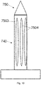
- the connecting element has a helical shape and consists of a head part 7402 and a body 7401. It has no thread in the part which comes into contact with the matrix material after assembly.
- the sheath 7503 is arranged there, which prevents direct contact of the metallic components of the connecting element with the reinforcing fiber structure.
- the cover 7503 remains in the fully consolidated and assembled ring beam.
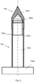
- the tip 751 has a pointed part 7501 which is screwed onto the thread 7502 . After the fiber composite material has consolidated, the tip is unscrewed and the nut for fixing the connecting element, optionally with a washer or another section of the connecting piece underneath, is screwed onto the thread 7502.
- FIG. 7 shows schematically an alternative embodiment 6 .
- the tip 750 is held on the upper end of the bolt 740 by means of an internal thread 7502 .
- FIGS 9 and 10 show schematically two variants of openings 7504 in the casing 7503.
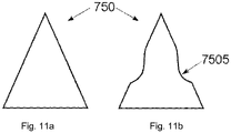
- Figures 11a and 11b show a frontal view of a tip ( Figure 11a ) and after a 90° rotation around the longitudinal axis ( Figure 11b ).
- the lateral flattening 7505 can be seen, which allows a wrench to be used to assemble or disassemble the tip 750 on the connector.
Description
Gegenstand der vorliegenden Erfindung ist ein Verbindungselement, mit dem ein Verbindungsbauteil mit einer Faserverbundstruktur, insbesondere einer speziellen Ringankerstruktur aus Faserverbundwerkstoff, verbunden werden kann. Der Ringanker ist Teil der Konstruktion eines Kopfmoduls (der Kabine) für ein Schienenfahrzeug, und soll im Crash-Fall dazu beitragen, die auftretenden Lasten abzubauen und zu verteilen.The subject matter of the present invention is a connecting element with which a connecting component can be connected to a fiber composite structure, in particular a special annular anchor structure made of fiber composite material. The ring anchor is part of the construction of a head module (the cabin) for a rail vehicle and is intended to help reduce and distribute the loads that occur in the event of a crash.
Insbesondere handelt es sich bei dem Kopfmodul um eine Konstruktion für Nahverkehrszüge, insbesondere U-Bahnen. Bei derartigen Zügen ist das Kopfmodul häufig in den Wagen integriert. Das Kopfmodul wird im Weiteren auch als Kabine bezeichnet.In particular, the head module is a construction for local trains, in particular subways. In such trains, the head module is often integrated into the car. The head module is also referred to below as the cabin.
Im Interesse der Material- und Energieeffizienz hat sich in den letzten Jahren der Einsatz leichter Materialien und der Prinzipien des Leichtbaus im Schienenfahrzeugbau immer weiter durchgesetzt. Insbesondere die Verwendung von Faserverbundmaterialien nimmt immer mehr zu. Auch für die Gestaltung der Kopfmodule von Schienenfahrzeugen trifft dies zu.In the interest of material and energy efficiency, the use of light materials and the principles of lightweight construction in rail vehicle construction has become increasingly popular in recent years. In particular, the use of fiber composite materials is increasing. This also applies to the design of the head modules of rail vehicles.
Bekannte Konstruktionen sehen hier vor, vorgefertigte Module auf die Unterkonstruktion, die den gesamten Wagen ohne Unterbrechung durchzieht, aufzusetzen.Known constructions provide for prefabricated modules to be placed on the substructure that runs through the entire car without interruption.
So ist Gegenstand der
In der
Aus der
In der
Aus der
Die
Die Fahrerkabine ist vorzugsweise als zweischalige Konstruktion ausgebildet. Die äußere Schale ist mit den drei Systemen, die im Crash-Falle die Stoßenergie in Verformung umwandeln, verbunden. Die innere Schale kleidet den eigentlichen, von Menschen nutzbaren, Innenraum aus. Beide Schalen sind als Faserverbundstrukturen ausgebildet, die keine wesentlichen Beiträge zur Crash-Resistenz liefern. Die äußere Schale gewährleistet die notwendige Steifigkeit der Konstruktion, indem sie als mehrlagige Faserverbundstruktur, optional mit zwischen den Faserschichten liegenden Kernen, realisiert ist. In den Faserschichten können gelegte, gewickelte oder geflochtene Fasergebilde eingesetzt werden. Zur Verbesserung der Steifigkeit sind auch UD-Faserstränge (unidirektionale Faserstränge) möglich. Vorteilhaft ist, dass die A-Säulen der äußeren Kabine keine speziellen Verstärkungen für die Kraftübertragung im Crash-Falle aufweisen. Dies verhindert, dass im Crash-Fall eine nachteilige Kraftübertragung auf den Ringanker erfolgt bzw. diese zumindest begrenzt wird. Bevorzugt sind die A-Säulen der äußeren Kabine zur Durchführung elektrischer Leitungen ausgestaltet. Die äußere Kabinenschale wird vorzugsweise aus Fasergelegen aufgebaut, die anschließend mit einem Matrixwerkstroff getränkt und konsolidiert werden. Auch der Aufbau aus bereits mit Matrixwerkstoff getränkten Fasergelegen ist möglich. Eine Verbindung der äußeren mit der inneren Schale erfolgt bevorzugt im Bereich der Frontscheibe. Hier sind die beiden Schalen miteinander verschraubt, verklebt oder in sonstiger Weise verbunden.The driver's cab is preferably designed as a double-shell construction. The outer shell is connected to the three systems that convert the impact energy into deformation in the event of a crash. The inner shell covers the actual interior space that can be used by people. Both shells are designed as fiber composite structures that make no significant contribution to crash resistance. The outer shell ensures the necessary rigidity of the construction by being realized as a multi-layer fiber composite structure, optionally with cores between the fiber layers. Laid, wound or braided fiber structures can be used in the fiber layers. To improve rigidity, UD fiber strands (unidirectional fiber strands) are also possible. It is advantageous that the A-pillars of the outer cabin do not have any special reinforcements for power transmission in the event of a crash. In the event of a crash, this prevents a disadvantageous transmission of force to the ring anchor or at least limits it. The A-pillars of the outer cabin are preferably designed for the passage of electrical lines. The outer cabin shell is preferably made up of non-woven fabrics, which are then impregnated and consolidated with a matrix material. It is also possible to build up fiber fabrics that have already been impregnated with matrix material. The outer shell is preferably connected to the inner shell in the area of the windscreen. Here the two shells are screwed together, glued or connected in some other way.
Eine besondere Bedeutung kommt dem Ringanker zu. Der Ringanker weist eine U-Form auf, bei der die beiden Enden des Ringankers an den oberen Längsträgern des nachfolgenden Wagenteils befestigt sind. Die Stirnfläche des Ringankers (entspricht der unteren Krümmung der U-Form) ist an der Innenseite der oberen Stirnseite der äußeren Kabinenschale angeordnet. Der Ringanker ist bevorzugt als Faserverbundbauteil ausgeführt. Dabei werden für den Ringanker UD-Faserlagen, die über die gesamte Länge des Ringankers, von einem Befestigungspunkt an einem oberen Längsträger des nachfolgenden Wagenteils zum anderen Befestigungspunkt an dem anderen oberen Längsträger des nachfolgenden Wagenteils verlaufen, genutzt. Diese UD-Faserlagen können alternierend mit Faserlagen eingesetzt werden, die abweichende Faserorientierungen aufweisen können. Bevorzugt sind Faserlagen aus Geweben. Insbesondere werden Faserlagen mit abweichenden Orientierungen bzw. Gewebe oder Geflechte genutzt, um die UD-Fasern vor dem Konsolidieren in ihrer Lage zu fixieren. Insbesondere werden bevorzugt Kohlefaserverbundmaterialien genutzt.The ring anchor is of particular importance. The ring anchor has a U-shape, in which the two ends of the ring anchor are attached to the upper longitudinal beams of the following car part. The end face of the ring anchor (corresponds to the lower curvature of the U-shape) is arranged on the inside of the upper end face of the outer cabin shell. The ring anchor is preferably designed as a fiber composite component. UD fiber layers are used for the ring anchor, which run over the entire length of the ring anchor, from one attachment point on an upper longitudinal member of the following car part to the other attachment point on the other upper longitudinal member of the following car part. These UD fiber layers can be used alternately with fiber layers that can have different fiber orientations. Fiber layers made of fabrics are preferred. In particular, fiber layers with different orientations or fabrics or braids are used to fix the UD fibers in their position before consolidation. In particular, carbon fiber composite materials are preferably used.
Die Verbindung der Enden des Ringankers zu den oberen Längsträgern des nachfolgenden Wagenteils wird bevorzugt durch Verbindungsstücke realisiert. Diese Verbindungsstücke unterstützen die Verbindung mit oberen Längsträgern des nachfolgenden Wagenteils indem sie bei hinreichender Festigkeit die notwendigen Öffnungen für die Montage (bevorzugt Verschraubung) zur Verfügung stellen. Bei diesen Öffnungen handelt es sich insbesondere um ein Schraubenöffnung bzw. mehrere Schraubenöffnungen je Ringankerende zu korrespondierenden Öffnungen in den oberen Längsträgern des nachfolgenden Wagenteils. Darüber hinaus sind optional Öffnungen vorgesehen, durch die Verbindungsbolzen bzw. Muttern, Schrauben oder Ähnliches in die Öffnungen eingeführt und ggf. bei Verschraubungen gegengehalten werden können.The connection of the ends of the ring anchor to the upper longitudinal beams of the following car part is preferably realized by connecting pieces. These connecting pieces support the connection with the upper longitudinal beams of the following car part by providing the necessary openings for assembly (preferably screw connections) with sufficient strength. These openings are, in particular, a screw opening or a plurality of screw openings for each end of the ring beam, corresponding to openings in the upper side members of the following carriage part. In addition, openings are optionally provided through which connecting bolts or nuts, screws or the like can be inserted into the openings and, if necessary, counter-held during screw connections.
Die Verbindungstücke müssen somit sowohl im Normalbetrieb als auch im Crash-Falle große Kräfte übertragen können.The connectors must therefore be able to transmit large forces both in normal operation and in the event of a crash.
Konventionelle Verfahren zur Anbindung der Verbindungsstücke an die Ringankerenden sehen vor, dass der bereits konsolidierte Ringanker mit Bohrungen versehen wird, durch die dann die Bolzen oder Schraubverbindungen, die die Verbindungsstücke an den Enden des Ringankers halten, geführt werden. Nachteilig an diesem Vorgehen ist, dass bei der Bohrung die Faserstruktur im Ringanker beschädigt wird. Darüber hinaus müssen die metallischen Bolzen bzw. Schrauben, die das Verbindungsstück halten sollen, gegen direkten Kontakt mit den offenen Enden der Kohlefaserverstärkungsmaterialien geschützt werden. Andernfalls könnte elektrochemische Korrosion die Bolzen oder Schrauben schwächen bzw. zerstören.Conventional methods for connecting the connecting pieces to the ring beam ends provide that the already consolidated ring beam is provided with bores through which the bolts or screw connections that hold the connecting pieces at the ends of the ring beam are then guided. The disadvantage of this procedure is that the fiber structure in the ring anchor is damaged during drilling. In addition, the metallic bolts intended to hold the connector must be protected from direct contact with the open ends of the carbon fiber reinforcement materials. Otherwise, electrochemical corrosion could weaken or destroy the bolts or screws.
Es stellt sich somit im Allgemeinen die Aufgabe, Verbindungselemente vorzuschlagen, die die Montage von Bauteilen, vorzugsweise metallischen Bauteilen, an Faserverbundbauteilen, insbesondere an Kohlefaserverbundbauteilen erleichtern. Im engeren Sinne gilt es, Verbindungselemente vorzuschlagen, mit denen die Verbindungsstücke an den Enden des Ringankers fixiert werden können, die die genannten Nachteile vermeiden. Die Verbindungsstücke sind dabei vorzugsweise metallisch, besonders bevorzugt aus Edelstahl oder Titan. Prinzipiell können die vorgeschlagenen Verbindungselemente aber auch zur Anbindung von Bauteilen bzw. Verbindungsstücken aus anderen Materialien genutzt werden.It is therefore generally the task of proposing connecting elements that facilitate the assembly of components, preferably metallic components, on fiber composite components, in particular on carbon fiber composite components. In a narrower sense, it is important to propose connecting elements with which the connecting pieces can be fixed at the ends of the ring anchor, avoiding the disadvantages mentioned. The connecting pieces are preferably metallic, particularly preferably made of stainless steel or titanium. In principle, however, the proposed connecting elements can also be used to connect components or connecting pieces made of other materials.
Erfindungsgemäß wird die Aufgabe mit einem Verbindungselement nach Anspruch 1 gelöst. Weiterhin wird die Aufgabe der Erfindung durch eine Verbindungsstruktur nach Anspruch 2 gelöst. Vorteilhafte Ausführungsformen des Verbindungselementes sowie der Verbindungsstruktur sind in den rückbezogenen Unteransprüchen offenbart. Eine Verwendung der erfindungsgemäßen Verbindungsstruktur ist in Anspruch 7 offenbart. Verwendungen des erfindungsgemäßen Verbindungselementes sind in den Ansprüchen 10, 11 und 12 offenbart.According to the invention, the object is achieved with a connecting element according to claim 1. Furthermore, the object of the invention is achieved by a connection structure according to claim 2. Advantageous embodiments of the connecting element and the connecting structure are disclosed in the dependent claims. A use of the connection structure according to the invention is disclosed in claim 7 . Uses of the connecting element according to the invention are disclosed in claims 10, 11 and 12.
Vorzugsweise wird der Ringanker gemeinsam mit der äußeren Kabinenschale gefertigt. Dabei wird ein Ringanker-Formteil, dass bereits die Faserverstärkungsstruktur des Ringankers aufweist, in die Form eingelegt, in der die äußere Kabinenschale gefertigt wird. Anschließend werden die Faserlagen des Ringankers und der äußeren Kabinenschale gemeinsam mit Matrixmaterial getränkt und dieses anschließend konsolidiert (das Matrixmaterial ausgehärtet). Es ist auch möglich, das Ringanker-Formteil bereits mit Matrixmaterial zu tränken und anschließend in die Form einzulegen bzw. auf eine Trägerkonstruktion aufzulegen, auf die dann die weiteren Faserlagen der äußeren Schale, ebenfalls als vorgetränkte Faserlagen (bspw. als Prepregs) aufgelegt werden. Auch hier wird anschließend konsolidiert.The ring anchor is preferably manufactured together with the outer cabin shell. In this case, a ring anchor molded part that already has the fiber reinforcement structure of the ring anchor is inserted into the mold in which the outer cabin shell is manufactured. Then the fiber layers of the ring anchor and the outer cabin shell are soaked together with matrix material and this is then consolidated (the matrix material hardened). It is also possible to already saturate the ring anchor molded part with matrix material and then place it in the mold or place it on a support structure, on which the other fiber layers of the outer shell, also as pre-impregnated fiber layers (e.g. as prepregs), are then placed. Here, too, consolidation is carried out afterwards.
Eine weitere bevorzugte Ausführungsform sieht vor, die äußere Kabinenschale und den Ringanker als unabhängige Bauteile zu fertigen und den konsolidierten Ringanker in die konsolidierte äußere Kabinenschale einzubringen und dort zu fixieren, vorzugsweise einzukleben.A further preferred embodiment provides for the outer cabin shell and the ring anchor to be manufactured as independent components and for the consolidated ring anchor to be introduced into the consolidated outer cabin shell and fixed there, preferably glued in place.
In noch einer weiteren bevorzugten Ausführungsform wird die Faserverstärkungsstruktur des Ringankers in der Form lagenweise aus Faserverstärkungslagen aufgebaut.In yet another preferred embodiment, the fiber reinforcement structure of the ring anchor is built up in layers from fiber reinforcement layers in the mold.
Der Ringanker besteht aus mehreren Lagen von Verstärkungsfasern. Dabei kommen sowohl Lagen unidirektionaler Fasern (UD-Lagen) als auch geflochtene oder bidirektional gelegt Lagen zum Einsatz. Die unterschiedlichen Lagen wechseln vorteilhaft einander ab. Insbesondere ist es vorteilhaft, einen Kern mit UD-Fasern, mit einer geflochtenen oder gewickelten äußeren Hülle, die die Form des Ringankers bestimmt, zu umgeben. Vorteilhaft können auch Gelege aus Rovings oder Prepregs als äußere Hülle genutzt werden. Vorzugsweise sind die einzelnen Lagen des Ringankers miteinander verbunden. Dies kann durch Vernähen, Stricken oder Klemmen passieren. Auch die Verwendung von Kunststoffverbindern ist möglich.The ring anchor consists of several layers of reinforcing fibers. Both layers of unidirectional fibers (UD layers) and braided or bidirectional layers are used. The different layers advantageously alternate with one another. In particular, it is advantageous to surround a core with UD fibers with a braided or wound outer sheath that determines the shape of the ring anchor. Scrims made of rovings or prepregs can also be used advantageously as the outer shell. The individual layers of the ring anchor are preferably connected to one another. This can be done by sewing, knitting or clamping. The use of plastic connectors is also possible.
Um das nachteilige Durchbohren des konsolidierten Faserverbundmaterials an den Enden des konsolidierten Ringankers zu vermeiden, werden die Bolzen bzw. Schrauben im trockenen oder im nassen (mit Matrixmaterial getränkten) unkonsolidierten Zustand des Matrixmaterials an den vorgesehenen Stellen vorrichtungsgebunden oder frei positioniert und durch die Verstärkungsfaserstruktur hindurchgeführt, wobei die Fasern verdrängt, jedoch nicht beschädigt werden.In order to avoid the disadvantageous piercing of the consolidated fiber composite material at the ends of the consolidated ring anchor, the bolts or screws are positioned in the dry or wet (soaked with matrix material) unconsolidated state of the matrix material at the intended points, either fixed to the device or freely and passed through the reinforcing fiber structure. whereby the fibers are displaced but not damaged.
In einer ersten Ausführungsform ist das Verbindungsstück einteilig gestaltet, so dass es das Ende des Ringankers vollständig umgibt und durch Bolzen oder Schrauben gehalten wird, die die Enden des Ringankers vollständig durchdringen.In a first embodiment, the connector is made in one piece so that it completely surrounds the end of the ring anchor and is held in place by bolts or screws which fully penetrate the ends of the ring anchor.
In einer weiteren Ausführungsform ist das Verbindungsstück mehrteilig, bevorzugt zweiteilig ausgeführt. Insbesondere bevorzugt ist eine zweiteilige Ausführung, bei der das Ende des Ringankers zwischen zwei halbschalenförmig ausgebildeten Teilen des Verbindungsstücks gehalten wird. Die beiden Teile des Verbindungsstücks sind dabei einander gegenüberliegend an einem Ende des Ringankers angeordnet.In a further embodiment, the connecting piece is designed in several parts, preferably in two parts. A two-part design is particularly preferred, in which the end of the ring anchor is held between two parts of the connecting piece designed in the shape of a half-shell. The two parts of the connecting piece are arranged opposite one another at one end of the ring anchor.
In einer dritten Ausführungsform ist das Verbindungsstück ein- oder mehrteilig ausgeführt, zeichnet sich jedoch dadurch aus, dass es das Ende des Ringankers nicht vollständig umschließt. Die Bolzen oder Verbindungsschrauben sind auf einer Seite in Unterlegscheiben oder Unterlegstücke auf der Oberfläche des Ringankermaterials und auf der anderen Seite durch das Material des Verbindungsstückes gelagert.In a third embodiment, the connecting piece is designed in one or more parts, but is characterized in that it does not completely enclose the end of the ring anchor. The bolts or connecting bolts are seated in washers or shims on the surface of the ring beam material on one side and through the material of the connector on the other side.
In einer ersten bevorzugten Verfahrensweise ist vorgesehen, das Verstärkungsfasermaterial in der angestrebten Form in trockenem oder im unkonsolidierten matrixmaterialgetränkten Zustand bereit zu stellen. Dies erfolgt, indem der Ringanker (als Abfolge von Lagen) in eine Form eingelegt wird und die Verbindungsstücke auf den Ringanker aufgelegt und anschließend die erfindungsgemäßen metallischen Verbindungselemente, wie Bolzen oder Schrauben, durch die Verstärkungsfaserlagen hindurchgedrängt werden. Alternativ können zuerst die Verbindungsstücke in die Form eingelegt und anschließend der unkonsolidierte Ringanker eingebracht werden. Ein weiterer Vorteil besteht darin, dass die Verbindungselemente und die Fügepartner in gemeinsamer Form angeordnet werden. Dies verhindert vorteilhaft ein lokales Verkippen, und das Laminat ist vor einer Zerstörung durch verschiebungsinduzierte lokale Lochleibung geschützt. Um eine sowohl absolute als auch relative Positionierung sicher zu stellen, können die Verbindungselemente optional auf einer Trägerplatte vorpositioniert werden. Beim Durchdringen der Faserlagen erfolgt vorteilhaft keine Beschädigung von Fasern. Anschließend kann das Verstärkungsfasermaterial der äußeren Gehäuseschale über dem Ringanker aufgebracht und ein gemeinsames Tränken mit Matrixmaterial bzw., wenn alle Fasermaterialien bereits getränkt sind, das Konsolidieren erfolgen. Vorteilhaft werden so die metallischen Verbindungselemente in die Matrix eingebunden und es entsteht kein Spalt, wie er beim Bohren nach bisherigen Verfahren zu erwarten ist. Es können daher keine korrosiven Medien in einen derartigen Spalt eindringen. Nach dem Konsolidieren ist der Ringanker, ausschließlich über das Matrixmaterial, stoffschlüssig mit der äußeren Gehäuseschale verbunden. Abschließend können äußere Gehäuseschale und Ringanker in einem Stück aus der Form entnommen werden.In a first preferred procedure, provision is made for the reinforcing fiber material to be made available in the desired form in a dry state or in the unconsolidated state saturated with matrix material. This is done by placing the ring anchor (as a sequence of layers) in a mold and placing the connecting pieces on the ring anchor and then pushing the metallic connecting elements according to the invention, such as bolts or screws, through the reinforcing fiber layers. Alternatively, the connecting pieces can be inserted into the mold first and then the unconsolidated ring anchor can be inserted. Another advantage is that the connecting elements and the joining partners are arranged in a common form. This advantageously prevents local tilting and the laminate is protected from destruction by displacement-induced local embedding. In order to ensure both absolute and relative positioning, the connecting elements can optionally be pre-positioned on a carrier plate. Advantageously, fibers are not damaged when penetrating the fiber layers. The reinforcing fiber material can then be applied to the outer housing shell over the ring anchor and impregnated with it together Matrix material or, if all fiber materials are already soaked, done the consolidation. In this way, the metallic connecting elements are advantageously integrated into the matrix and no gaps arise, as is to be expected with drilling using previous methods. Therefore, no corrosive media can penetrate into such a gap. After consolidation, the ring anchor is materially connected to the outer housing shell exclusively via the matrix material. Finally, the outer housing shell and ring anchor can be removed from the mold in one piece.
In einer zweiten bevorzugten Verfahrensweise wird das Verstärkungsfasermaterial des Ringankers in einer eigenen Form in trockenem oder im unkonsolidierten matrixmaterialgetränkten Zustand bereitgestellt. Anschließend werden die erfindungsgemäßen Bolzen oder Schrauben durch die Verstärkungsfaserlagen hindurchgedrängt und die Verbindungsstücke installiert. Auch dies erfolgt vorteilhaft ohne Beschädigung der Fasern des Verstärkungsfasermaterials. Danach kann das Verstärkungsfasermaterial, falls es im trockenen Zustand bereitgestellt wurde, mit Matrixmaterial getränkt werden. Anschließend kann in beiden Fällen (trocken oder getränkt bereitgestelltes Verstärkungsfasermaterial) der vorbereitete Ringanker entnommen und in die Form zur Herstellung der äußeren Schale eingelegt werden. Anschließend erfolgt die Weiterverarbeitung wie in der ersten bevorzugten Verfahrensweise.In a second preferred procedure, the reinforcing fiber material of the ring anchor is provided in a separate form in a dry state or in an unconsolidated state soaked with matrix material. The bolts or screws of the present invention are then forced through the reinforcing fiber layers and the connectors installed. This also takes place advantageously without damaging the fibers of the reinforcing fiber material. Thereafter, the reinforcing fiber material, if it was provided in a dry state, can be impregnated with matrix material. In both cases (reinforced fiber material provided dry or soaked), the prepared ring anchor can then be removed and placed in the mold for producing the outer shell. The further processing then takes place as in the first preferred procedure.
Eine dritte bevorzugte Verfahrensweise sieht vor, entsprechend der zweiten bevorzugten Verfahrensweise vorzugehen, jedoch das getränkte Verstärkungsfasermaterial nach dem Anbringen der Verbindungsstücke teilzukonsolidieren und erst danach in die Form zur Herstellung der äußeren Schale zu überführen.A third preferred procedure envisages proceeding in accordance with the second preferred procedure, but partially consolidating the impregnated reinforcing fiber material after the attachment of the connecting pieces and only then transferring it to the mold for producing the outer shell.
Die erfindungsgemäßen Verbindungselemente (bspw. als Bolzen bzw. Schrauben) können als einzelne Bauteile oder an einem Teil des Verbindungsstücks fixiert (bspw. aufgeschweißt, geklebt) bereitgestellt werden. Sie bestehen bevorzugt aus metallischen Werkstoffen, besonders bevorzugt aus Stahl. Für Aufgabenstellungen, die andere Anforderungen an Festigkeit und Korrosionsbeständigkeit stellen, können die Verbindungselemente jedoch auch aus anderen Materialien, bspw. Kunststoff, FKV, Keramik etc. bestehen.The connecting elements according to the invention (e.g. as bolts or screws) can be provided as individual components or fixed (e.g. welded, glued) to a part of the connection piece. They are preferably made of metallic materials, particularly preferably steel. However, for tasks that place different demands on strength and corrosion resistance, the connecting elements can also be made of other materials, e.g. plastic, FRP, ceramics, etc.
Die Verbindungselemente werden im Zuge einer bevorzugten Variante des Verfahrens durch die dafür vorgesehenen Öffnungen der Verbindungsstücke und die Faserlagen hindurchgeführt. Nach dem Konsolidieren des Ringankers werden vorzugsweise Unterlegstücke (-scheiben) oder ein weiteres Teilstück der Verbindungsstücke auf das jeweilige konsolidierte Ende des Ringankers aufgebracht und dort fixiert. Dies erfolgt bspw. durch Verschrauben oder Vernieten der Enden der Verbindungselemente. In jeder Ausführungsform durchdringen die Verbindungselemente den Ringanker vollständig.In the course of a preferred variant of the method, the connecting elements are passed through the openings provided for this purpose in the connecting pieces and the fiber layers. After the ring anchor has been consolidated, washers or another section of the connecting pieces are preferably applied to the respective consolidated end of the ring anchor and fixed there. This is done, for example, by screwing or riveting the ends of the connecting elements. In each embodiment, the connecting elements completely penetrate the ring anchor.
Die Verbindungselemente als einzelne Bauteile weisen einen Kopf und einen stabförmigen, längserstreckten Körper auf, der einen geringeren Querschnitt als der Kopf besitzt. Vorzugsweise weisen die Verbindungselemente eine Rotationssymmetrie um die Längsachse des Körpers auf. Dies trifft zumindest auf den Körper selbst zu, der bevorzugt einen kreisförmigen Querschnitt aufweist. Sie entsprechen somit in ihrer äußeren Form herkömmlichen Bolzen bzw. Schrauben. In einer weiteren Ausführungsform weisen die Verbindungselemente einen rautenförmigen Querschnitt auf, dessen größte Ausdehnung in Belastungsrichtung liegt. Dies vermeidet vorteilhaft eine starke Faserumlenkung und die damit einhergehenden Aufziehspannungen an den Flanken des Verbindungselementes (durch das Ausrichten der Fasern unter Last) wird verringert, da das Loch durch das Verbindungselement belastungsorientiert verfüllt wird.The connecting elements as individual components have a head and a rod-shaped, elongate body which has a smaller cross section than the head. Preferably, the connecting elements have a rotational symmetry about the longitudinal axis of the body. This applies at least to the body itself, which preferably has a circular cross-section. In terms of their external shape, they therefore correspond to conventional bolts or screws. In a further embodiment, the connecting elements have a diamond-shaped cross section, the greatest extent of which is in the direction of loading. This advantageously avoids strong fiber deflection and the associated pull-up stresses on the flanks of the connecting element (due to the alignment of the fibers under load) is reduced, since the hole is filled by the connecting element in a load-oriented manner.
An dem Ende des erfindungsgemäßen Verbindungselements, das dem Kopf abgewandt ist, ist eine Spitze angeordnet, die das Durchdringen der Faserlagen des Faserverbundbauteils im trockenen oder matrixgetränkten, unkonsolidierten Zustand unterstützt. Das metallische Verbindungsstück weist Öffnungen zur Durchführung des Körpers des Verbindungselementes auf oder ist selbst Kopf eines oder mehrerer Verbindungselemente. In dem Bereich, der mit dem Matrixmaterial des Faserverbundbauteils, mindestens jedoch in dem Bereich, der mit den Verstärkungsfasern des Faserverbundbauteils in Berührung kommt, weist das erfindungsgemäße Verbindungselement eine Umhüllung auf.At the end of the connecting element according to the invention, which faces away from the head, a tip is arranged, which supports the penetration of the fiber layers of the fiber composite component in the dry or matrix-impregnated, unconsolidated state. The metal connector has openings for the passage of the body of the connector or is itself the head of one or more connectors. In the area that comes into contact with the matrix material of the fiber composite component, but at least in the area that comes into contact with the reinforcing fibers of the fiber composite component, the connecting element according to the invention has a sheath.
Bevorzugt sind die Verbindungselemente (Schrauben, Bolzen) selbst als Dorne ausgebildet und müssen daher nach dem erfolgreichen Durchdringen der Faserlagen nicht entfernt werden. In einer ersten einfachen Ausführungsform sind dabei die Verbindungselemente an der Seite, die durch die Faserlagen dringt, zugespitzt ausgeführt.The connecting elements (screws, bolts) themselves are preferably designed as mandrels and therefore do not have to be removed after the fiber layers have been successfully penetrated. In a first simple embodiment the connecting elements on the side that penetrates through the fiber layers are tapered.
Die Erfindung sieht vor, dass die zugespitzte Ausführung der Verbindungselemente durch eine abnehmbare Spitze realisiert wird. Die abnehmbare Spitze kann dabei entweder auf einen Außengewindeabschnitt an dem Ende des Verbindungselementes, mit dem die Faserlagen durchdrungen werden, aufgeschraubt sein oder die abnehmbare Spitze ist in einer axialen Öffnung an dem Ende des Verbindungselementes, mit dem die Faserlagen durchdrungen werden, eingesetzt oder eingeschraubt. Wenn die Spitze in die axiale Öffnung lediglich eingesetzt ist, kann sie durch eine magnetische Verbindung, einen Federring oder Ähnliches in ihrer Position gehalten werden.The invention provides that the pointed design of the connecting elements is realized by a removable tip. The detachable tip can either be screwed onto an externally threaded section at the end of the connecting element with which the fiber layers are penetrated, or the detachable tip is inserted or screwed into an axial opening at the end of the connecting element with which the fiber layers are penetrated. When the tip is merely inserted into the axial hole, it can be held in position by a magnetic connection, spring washer or the like.
Eine vorteilhafte Weiterbildung sieht vor, dass die Spitze, falls eine Schraubverbindung zu dem Verbindungselement vorliegt, an mindestens zwei gegenüberliegenden Seiten abgeflacht ist, um das Ansetzen eines Schraubenschlüssels, bevorzugt eines Maulschlüssels, zur Montage bzw. Demontage zu ermöglichen. Der Übergang von der Abflachung zum weiteren Verlauf der abnehmbaren Spitze in Richtung des Verbindungselementes ist bevorzugt gerundet ausgeführt, damit die Fasern beim Durchdringen der Lagen auch in diesem Bereich abgleiten können.An advantageous further development provides that the tip, if there is a screw connection to the connecting element, is flattened on at least two opposite sides in order to enable a wrench, preferably an open-end wrench, to be used for assembly or disassembly. The transition from the flattening to the further course of the detachable tip in the direction of the connecting element is preferably rounded so that the fibers can also slide off in this area when penetrating the layers.
In einer bevorzugten Vorgehensweise sollen die Gewindegänge von Schrauben geschützt werden, d.h. es soll vermieden werden, dass sich die Gewindegänge mit Harz füllen. Dazu werden sowohl die Gewindegänge als auch die den Dorn ausbildenden Umhüllungen mit geeigneten Trennmitteln versehen.A preferred approach is to protect the threads of screws, i.e. avoid filling the threads with resin. For this purpose, both the threads and the coverings forming the mandrel are provided with suitable separating agents.
Vorzugsweise wird beim Durchstoßen der Faserlagen die Oberfläche des Verbindungselementes mit einem reibungsreduzierenden Mittel beschichtet.When the fiber layers are pierced, the surface of the connecting element is preferably coated with a friction-reducing agent.
Bevorzugt werden die Verbindungselemente beim Durchdringen der Faserlagen, insbesondere bei Kohlefasern, mit einer Oberflächenbeschichtung versehen, die einen direkten, elektrisch leitfähigen Kontakt zwischen dem Material der Verbindungselemente und den Kohlenstoffasern unterbindet oder zumindest stark reduziert. Das reibungsreduzierende Mittel und die Oberflächenbeschichtung können identisch sein, falls das gewählte Material die notwendigen Eigenschaften aufweist. Derartige Materialien sind aus dem Stand der Technik bekannt.When penetrating the fiber layers, in particular in the case of carbon fibers, the connecting elements are preferably provided with a surface coating which prevents or at least greatly reduces direct, electrically conductive contact between the material of the connecting elements and the carbon fibers. The friction reducing agent and the surface coating can be identical if the chosen material has the necessary properties. Such materials are known from the prior art.
Verbindungselemente können nachteilig beim Durchdringen an Fasern hängen bleiben und deren Bruch verursachen, insbesondere, wenn sie mit einem Außengewinde versehen sind. Vorteilhaft weisen daher die Verbindungselemente eine Umhüllung auf. Diese ist vorzugsweise in der Art einer zumindest am Körper der Verbindungselemente eng anliegenden Röhre mit glatter Außenwandung ausgeführt. Bei mit einem Außengewinde versehenen Verbindungselement-Körpern kann diese Umhüllung auch aufgeschraubt sein. In einer bevorzugten Verfahrensweise wird diese Umhüllung nach dem Durchdringen der Faserlagen abgezogen bzw. abgeschraubt und entnommen, so dass sie nicht im Ringanker verbleibt. Eine weitere bevorzugte Ausführungsform sieht vor, dass die Umhüllung im Ringanker verbleibt und im Zuge der Tränkung mit Matrixmaterial und anschließender Konsolidierung in die Matrix mit eingebunden wird.Fasteners can disadvantageously snag and break fibers during penetration, particularly when externally threaded. Therefore, the connecting elements advantageously have a covering. This is preferably in the form of a tube with a smooth outer wall that fits snugly at least on the body of the connecting elements. In the case of connecting element bodies provided with an external thread, this covering can also be screwed on. In a preferred procedure, this covering is pulled off or unscrewed and removed after penetrating the fiber layers, so that it does not remain in the ring anchor. A further preferred embodiment provides that the covering remains in the ring anchor and is integrated into the matrix in the course of impregnation with matrix material and subsequent consolidation.
In einer bevorzugten Ausführungsform ist die Umhüllung nicht auf den Körper des Verbindungselements aufgeschraubt, jedoch über die gesamte, mit dem Faserverbundmaterial in Verbindung stehende Länge des Verbindungselementes ausgeführt. So ist es vorteilhaft möglich, die übrigen Teile des Verbindungselements aus der Umhüllung heraus zu ziehen und eine Wechselbarkeit des Verbindungselementes bzw. die Austauschbarkeit des vom Verbindungselement gehaltenen Verbindungsstückes zu ermöglichen.In a preferred embodiment, the cover is not screwed onto the body of the connecting element, but runs over the entire length of the connecting element connected to the fiber composite material. It is thus advantageously possible to pull the remaining parts of the connecting element out of the casing and to enable the connecting element to be changed or the connecting piece held by the connecting element to be exchanged.
Auch zur Verhinderung des elektrisch leitenden Kontakts zwischen metallischem Material von Bestandteilen des Verbindungselementes und der Kohlefaserverstärkung kann die Umhüllung vorteilhaft genutzt werden. Die Umhüllung überdeckt dabei mindestens den Teil des Verbindungselementes, der mit dem Verstärkungsfasermaterial in Verbindung kommt, optional den gesamten mit Matrixmaterial in Kontakt tretenden Abschnitt des Verbindungselementes.The casing can also be advantageously used to prevent electrically conductive contact between the metallic material of components of the connecting element and the carbon fiber reinforcement. The covering covers at least that part of the connecting element that comes into contact with the reinforcing fiber material, optionally the entire section of the connecting element that comes into contact with matrix material.
Die Spitze steht in ihrer Umfangsrichtung vorzugsweise soweit über den Querschnitt des Verbindungselement-Körpers über, dass ein stufenloser Abschnitt mit der Umhüllung gebildet wird. Dies vermeidet das Hängenbleiben von Fasern an der Kante der Umhüllung,In its circumferential direction, the tip preferably protrudes beyond the cross section of the connecting element body to such an extent that a continuous section is formed with the casing. This avoids fiber snagging on the edge of the wrap,
Bevorzugt besteht die Umhüllung aus einem Kunststoffmaterial, besonders bevorzugt aus demselben Material, das als Matrixmaterial zum Einsatz kommt. Es ist aber auch möglich, ein geeignetes Thermoplast oder einen anderen Kunststoff einzusetzen, das nicht chemisch durch das Matrixmaterial angegriffen wird.The covering preferably consists of a plastic material, particularly preferably of the same material that is used as the matrix material. However, it is also possible to use a suitable thermoplastic or another plastic that is not chemically attacked by the matrix material.
Auch eine Beschichtung aus Matrixmaterial auf den Verbindungselementen ist möglich. Diese ist dann auf den Abschnitt des Verbindungselementes beschränkt, der im montierten Zustand innerhalb des Ringankers verläuft.A coating of matrix material on the connecting elements is also possible. This is then limited to the section of the connecting element that runs inside the ring anchor in the assembled state.
Eine vorteilhafte Weiterbildung der Umhüllung sieht vor, dass diese durchbrochen ist, um das Eindringen von Matrixmaterial bis direkt zum Verbindungselement-Körper zu ermöglichen. Diese Durchbrüche sind bevorzugt achsenparallel zum Körper des Verbindungselementes verlaufende längliche Öffnungen, bevorzugt über annähernd die gesamte Länge der Umhüllung oder auch als kreisförmig oder ellipsenförmig (vorzugsweise große Halbachse der Ellipse parallel zur Längsachse des Verbindungselementes) ausgeführt. Vorzugsweise sind dabei jedoch Kanten zu vermeiden (bzw. abzurunden), an denen die Fasern des Faserverstärkungsmaterials hängen bleiben könnten. Durch die Öffnungen kann Matrixmaterial eindringen, die Fasern des Verstärkungsmaterials überbrücken aufgrund ihrer Biegeradien diese Öffnungen jedoch, ohne Kontakt zum Körper des Verbindungselementes herzustellen.An advantageous development of the cover provides that it is perforated in order to allow matrix material to penetrate directly to the connecting element body. These openings are preferably elongate openings running parallel to the axis of the body of the connecting element, preferably over almost the entire length of the casing or as circular or elliptical (preferably large semi-axis of the ellipse parallel to the longitudinal axis of the connecting element). Preferably, however, edges should be avoided (or rounded off) on which the fibers of the fiber reinforcement material could get caught. Matrix material can penetrate through the openings, but the fibers of the reinforcing material bridge these openings due to their bending radii without making contact with the body of the connecting element.
In einer weiteren vorteilhaften Weiterentwicklung bilden die den Dorn ausbildenden Umhüllungen selbst später im Sinne eines eingebetteten Innengewindes nutzbare FunktionselementeIn a further advantageous further development, the coverings forming the mandrel themselves later form functional elements that can be used in the sense of an embedded internal thread
Nach dem Einbringen der Verbindungselemente und dem Konsolidieren des Matrixmaterials des Ringankers (dies erfolgt optional gemeinsam mit dem Konsolidieren der äußeren Hülle) werden die Verbindungselemente fixiert. Dies erfolgt bevorzugt, indem diese auf der dem Kopf der Verbindungselemente gegenüberliegenden Seite eine Mutter aufgeschraubt wird oder das herausstehende Ende vernietet wird.After inserting the connecting elements and consolidating the matrix material of the ring anchor (this is optionally done together with the consolidation of the outer shell), the connecting elements are fixed. This is preferably done by screwing a nut on the side opposite the head of the connecting elements or by riveting the protruding end.
Auch wenn die erfindungsgemäßen Verbindungselemente für den Einsatz an Kohlefaserverbundwerkstoffen entwickelt wurden, ist der Einsatz mit anderen Faserverbundwerkstoffen, insbesondere glasfaserverstärkten Kunststoffen, ohne weiteres möglich. Vorteilhaft ist eine Verwendung zur Verbindung von Bauteilen aus verschiedenen Materialien (bspw. Glas, Holz, Metall, Faserverbundwerkstoffen, Kunststoffen ohne Faserverstärkung, keramischen oder mineralischen Stoffen etc.) mit Bauteilen aus Faserverbundmaterial möglich.Even if the connecting elements according to the invention were developed for use with carbon fiber composite materials, use with other fiber composite materials, in particular glass fiber reinforced plastics, is easily possible. Use for connecting components is advantageous from different materials (e.g. glass, wood, metal, fiber composite materials, plastics without fiber reinforcement, ceramic or mineral materials etc.) with components made of fiber composite material possible.
Die folgenden Figuren erläutern beispielhaft die erfindungsgemäßen Verbindungselemente in ihrer bevorzugten Verwendung zur Anbindung von Verbindungsstücken an einen Ringanker für Kopfmodule von Schienenfahrzeugen.The following figures explain by way of example the connection elements according to the invention in their preferred use for connecting connection pieces to a ring anchor for head modules of rail vehicles.
In den unteren Teil der inneren Schale sind die Brüstungsverstärkung 711 und die UD-Gurte 710 integriert, die die Kraft von der Brüstungsverstärkung 711 auf die Einleitpunkte 712 in die unteren Längsträger des nachfolgenden Wagenteils übertragen.The
Unterhalb des unteren Teils der inneren Schale verläuft das untere Crash-Durchleitungselement 730. An der Frontseite der Kabine ist die Platte 734 dargestellt. Dieser nachgeordnet ist die Crash-Box 733. Im Crash-Falle erfolgt der Aufprall auf der Platte 734, die die Kraft an die Crash-Box 733 weitergibt und dort weitestgehend abbaut. Verbliebene Stoßenergie wird in das untere Crash-Durchleitungselement 730 weitergeleitet und dort am Befestigungspunkt 732 in die Untergestellstütze des nachfolgenden Wagenteils übergeben. Im horizontalen Teil des unteren Crash-Durchleitungselementes 730 sind die Öffnungen 731 zur Befestigung der Mittelpufferkupplung erkennbar.Below the lower portion of the inner shell runs the lower
- 701701
- innere Schaleinner shell
- 702702
- äußere Schaleouter shell
- 703703
- Seitenfensteröffnungside window opening
- 704704
- Frontfensteröffnungfront window opening
- 705705
- A-SäuleA pillar
- 706706
- Abdeckklappe der MittelpufferkupplungCover flap for the central buffer coupling
- 707707
- Inneneinbauteninternal fixtures
- 710710
- UD-Gurt der BrüstungsverstärkungParapet Reinforcement UD Belt
- 711711
- Brüstungsverstärkungparapet reinforcement
- 712712
- Einleitpunkt der Kräfte von der Brüstungsverstärkung in den unteren Längsträger des nachfolgenden WagensPoint of introduction of the forces from the parapet reinforcement into the lower side member of the following car
- 720720
- Ringankerring anchor
- 721721
- Verbindungsstückconnector
- 72117211
- Unteres Teilstücklower section
- 72127212
- Oberes Teilstückupper section
- 72137213
- Frontteilstückfront section
- 72147214
- Öffnungenopenings
- 72157215
- Öffnungenopenings
- 72167216
- Öffnungenopenings
- 72177217
- Montageöffnungenmounting holes
- 730730
- unteres Crash-Durchleitungselementlower crash conduction element
- 73017301
- Abschnitt des Crash-Durchleitungselement von der Crash-Box zum horizontalen TeilSection of the crash conduction element from the crash box to the horizontal part
- 73027302
- horizontaler Teilhorizontal part
- 73037303
- Abschnitt des Crash-Durchleitungselement vom horizontalen Teil zum Befestigungselement an der UntergestellstützeSection of the crash conduction element from the horizontal part to the fastener on the chassis support
- 731731
- Bohrungen zur Befestigung der MittelpufferkupplungHoles for attaching the central buffer coupling
- 732732
- Befestigungsvorrichtung des unteren Crash-Elements an der UntergestellstützeFastening device for the lower crash element on the underframe support
- 733733
- Crash-Boxcrash box
- 734734
- Platteplate
- 740740
- Verbindungsbolzen zur Befestigung des Verbindungsstücks am RingankerConnecting bolt for attaching the connecting piece to the ring anchor
- 74017401
- Bolzenkörperbolt body
- 74027402
- Bolzenkopfbolt head
- 750750
- Spitze zur Unterstützung der Durchdringung des FaserverstärkungsmaterialsTip to help penetrate the fiber reinforcement material
- 75017501
- zugespitzter Teilpointed part
- 75027502
- Gewindethread
- 75037503
- Umhüllung des VerbindungsbolzensCover of the connecting bolt
- 75047504
- Durchbrüche in der Umhüllung des VerbindungsbolzensBreakthroughs in the casing of the connecting bolt
- 75057505
- Abflachung der Spitzeflattening of the tip
Claims (11)
- A connecting element for fixing connection pieces (721) to fiber composite components made up of at least one fiber ply and matrix material, having a screw- or bolt-like shape with a head (7402) and a body (7401), wherein the body (7401) has an elongated shape with a smaller cross section than the head (7402), and wherein, at the end facing away from the head (7402), a tip (750) is arranged that is configured to assist the penetration of the fiber plies of the fiber composite component in the dry state or unconsolidated state impregnated with matrix, wherein the connecting element (740) is configured to be passed through openings (7216) of the connection piece (721) or wherein the head (7401) of the connecting element (740) is configured as a connection piece (721), and wherein the connecting element (740) has a casing (7503) in the area configured come into contact with the matrix material of the fiber composite component, but at least in the area configured to come into contact with the reinforcing fibers of the fiber composite component,
characterized in that
the tip (750) has flat areas (7505) which facilitate the application of a spanner for installation or uninstallation of the tip (750) on the connecting element (740). - A connecting structure for fixing to fiber composite components made up of at least one fiber ply and matrix material, having a connection piece (721) and a connecting element (740) having a screw- or bolt-like shape with a head (7402) and a body (7401), wherein the body (7401) has an elongated shape with a smaller cross section than the head (7402), and wherein, at the end facing away from the head (7402), a tip (750) is arranged that is configured to assist the penetration of the fiber plies of the fiber composite component in the dry state or unconsolidated state impregnated with matrix, wherein the connection piece (721) has openings (7216) for passing the body (7401) of the connecting element (740) therethrough or is itself configured as the head (7401) of one or more connecting elements (740), wherein the connecting element (740) has a casing (7503) in the area configured come into contact with the matrix material of the fiber composite component, but at least in the area configured to come into contact with the reinforcing fibers of the fiber composite component,
wherein
the tip (750) has flat areas (7505) which facilitate the application of a spanner for installation or uninstallation of the tip (750) on the connecting element (740). - The connecting element according to claim 1, characterized in that the tip (750) is screwed onto an external thread of the connecting element (740).
- The connecting element according to claim 1, characterized in that the tip (750) is screwed onto an internal thread of the connecting element (740) which is arranged axially at the end of the connecting element (740).
- The connecting element according to claim 1, characterized in that the tip (750) is inserted into an opening of the connecting element (740) which is arranged axially at the end of the connecting element (740).
- Use of a connecting structure according to claim 2, characterized in that the casing (7503) is removed from the fiber composite component after penetration of the fiber plies and before consolidation, or in that the casing (7503) remains in the fiber composite component.
- The connecting element according to any of claims 1 or 3 to 5, characterized in that the casing (7503) has perforations (7504) which allow matrix material to enter as far as the surface of the connecting element (740).
- The connecting structure according to claim 2, characterized in that the width of the perforations (7504) perpendicular to the longitudinal axis of the connecting element (740) is so small that the reinforcing fibers bridge the perforations (7504) and, due to their bending radius, do not reach the material surface of the connecting element (740).
- Use of a connecting element according to any of claims 1, 3 to 5 or 7 for fixing a metallic connection piece (721) to a ring beam made of fiber composite material for a head module of a rail vehicle, wherein, during the production of the ring beam (720), the connecting element (740) is fed through openings of the connection piece (721) provided for this and through the dry fiber plies or unconsolidated fiber plies, impregnated with matrix, of the ring beam (720).
- Use of a connecting element according to any of claims 1, 3 to 5 or 7 for fixing a metallic connection piece (721) to a ring beam (720) made of fiber composite material for a head module of a rail vehicle, wherein at least one connecting element (740) is arranged on the connection piece (721) and is fed through the dry fiber plies or unconsolidated fiber plies, impregnated with matrix, of the ring beam (720), and is fixed on the side of the ring beam (720) opposite the connection piece (721).
- Use of a connecting element according to any of claims 1, 3 to 5 or 7 for fixing a component made of glass, wood, metal, fiber composite materials, plastics without fiber reinforcement, ceramic or mineral substances to a component made of fiber composite material.
Applications Claiming Priority (2)
| Application Number | Priority Date | Filing Date | Title |
|---|---|---|---|
| DE102017102562.6A DE102017102562A1 (en) | 2017-02-09 | 2017-02-09 | Connecting element for connecting a component to a fiber composite structure |
| PCT/EP2018/053216 WO2018146218A1 (en) | 2017-02-09 | 2018-02-08 | Connecting element for attaching a component to a fiber composite structure |
Publications (2)
| Publication Number | Publication Date |
|---|---|
| EP3580052A1 EP3580052A1 (en) | 2019-12-18 |
| EP3580052B1 true EP3580052B1 (en) | 2022-11-30 |
Family
ID=61189465
Family Applications (1)
| Application Number | Title | Priority Date | Filing Date |
|---|---|---|---|
| EP18704233.8A Active EP3580052B1 (en) | 2017-02-09 | 2018-02-08 | Connecting element for attaching a component to a fiber composite structure |
Country Status (7)
| Country | Link |
|---|---|
| US (1) | US20200001904A1 (en) |
| EP (1) | EP3580052B1 (en) |
| JP (1) | JP6928099B2 (en) |
| CN (1) | CN110248798A (en) |
| DE (1) | DE102017102562A1 (en) |
| ES (1) | ES2937036T3 (en) |
| WO (1) | WO2018146218A1 (en) |
Families Citing this family (1)
| Publication number | Priority date | Publication date | Assignee | Title |
|---|---|---|---|---|
| DE102020201609A1 (en) | 2020-02-10 | 2021-08-12 | Elringklinger Ag | Method for functionalizing a fiber-reinforced plastic component, functional element for functionalizing a fiber-reinforced plastic component, component composite and device for functionalizing a fiber-reinforced plastic component |
Family Cites Families (22)
| Publication number | Priority date | Publication date | Assignee | Title |
|---|---|---|---|---|
| GB1029253A (en) * | 1964-03-18 | 1966-05-11 | Federal Screw Works | Improved taper bolt assembly |
| DE2750829C2 (en) * | 1977-11-14 | 1982-12-16 | Camloc Fastener Gmbh, 6233 Kelkheim | Device for inserting and potting a threaded dowel or the like to be fastened in a lightweight composite sheet with potting compound. |
| SE431668B (en) * | 1982-07-06 | 1984-02-20 | Andersson Soeren | frame socket |
| JPS62264896A (en) | 1986-05-12 | 1987-11-17 | 町田 輝史 | Manufacture of fiber-reinforced composite material with joining hole |
| US4900208A (en) * | 1988-06-09 | 1990-02-13 | Kaiser Norbert O | Roofing fastener |
| DE3916515C1 (en) * | 1989-05-20 | 1990-11-08 | Friedr. Trurnit Gmbh, 5990 Altena, De | |
| US5245743A (en) * | 1990-07-26 | 1993-09-21 | Fatigue Technology, Inc. | Method of installing a nut mounting grommet |
| DE19725905A1 (en) | 1997-06-13 | 1998-12-17 | Abb Daimler Benz Transp | Rail vehicle with a head module made of a fiber composite material |
| FR2834926B1 (en) * | 2002-01-22 | 2004-03-12 | Renault | METHOD FOR MANUFACTURING A SYNTHETIC MOTOR CRADLE |
| WO2005059377A1 (en) * | 2003-12-18 | 2005-06-30 | Loi & Tran Pty. Limited | Two-piece cutting screw |
| CN2735004Y (en) * | 2004-09-30 | 2005-10-19 | 彭保朝 | Plastic anchoring sleeve |
| ES2499029T3 (en) | 2008-09-15 | 2014-09-26 | Voith Patent Gmbh | Vehicle head for fixing on the front side of a rail-guided vehicle, in particular of a rail vehicle |
| US9140286B2 (en) * | 2009-01-30 | 2015-09-22 | Clifford Dent | Omnidirectional breakaway support system and connector |
| JP5625260B2 (en) * | 2009-04-21 | 2014-11-19 | 株式会社豊田自動織機 | Fiber reinforced composite material and fastening structure of fiber reinforced composite material |
| GB0906953D0 (en) | 2009-04-23 | 2009-06-03 | Airbus Uk Ltd | Composite structure |
| DE102010035950A1 (en) * | 2010-08-31 | 2012-03-01 | Audi Ag | Method for producing a nail connection between at least two parts to be joined |
| CN104093549B (en) * | 2012-02-03 | 2017-07-18 | 斯奈克玛 | Method and system for equipment to be attached to the structure being made up of composite |
| DE102012021493A1 (en) * | 2012-10-31 | 2014-04-30 | Daimler Ag | Cross member arrangement and manufacturing method |
| US9303671B2 (en) * | 2013-01-15 | 2016-04-05 | GM Global Technology Operations LLC | Method of isolating metallic fasteners in composite panels |
| US9023455B2 (en) * | 2013-01-30 | 2015-05-05 | Ford Global Technologies, Llc | Method of making reinforced composite articles with reduced fiber content in local areas and articles made by the method |
| CN203585035U (en) * | 2013-11-25 | 2014-05-07 | 西安欧德隆电气有限公司 | Prestressed locking screw sleeve |
| DE102015106563B4 (en) | 2015-04-28 | 2024-03-21 | Airbus Operations Gmbh | Method for connecting fiber-reinforced structural components |
-
2017
- 2017-02-09 DE DE102017102562.6A patent/DE102017102562A1/en active Pending
-
2018
- 2018-02-08 US US16/484,609 patent/US20200001904A1/en not_active Abandoned
- 2018-02-08 EP EP18704233.8A patent/EP3580052B1/en active Active
- 2018-02-08 CN CN201880010523.0A patent/CN110248798A/en active Pending
- 2018-02-08 JP JP2019543120A patent/JP6928099B2/en active Active
- 2018-02-08 WO PCT/EP2018/053216 patent/WO2018146218A1/en unknown
- 2018-02-08 ES ES18704233T patent/ES2937036T3/en active Active
Also Published As
| Publication number | Publication date |
|---|---|
| ES2937036T3 (en) | 2023-03-23 |
| EP3580052A1 (en) | 2019-12-18 |
| JP6928099B2 (en) | 2021-09-01 |
| US20200001904A1 (en) | 2020-01-02 |
| CN110248798A (en) | 2019-09-17 |
| JP2020508253A (en) | 2020-03-19 |
| DE102017102562A1 (en) | 2018-08-09 |
| WO2018146218A1 (en) | 2018-08-16 |
Similar Documents
| Publication | Publication Date | Title |
|---|---|---|
| EP2788247B1 (en) | Body component | |
| WO2015091240A1 (en) | Interconnection-type vehicle body structure | |
| DE202005010964U1 (en) | Hybrid fastener | |
| EP3079927B1 (en) | Assembly comprising a frame element and a connecting element, and method for securing a connecting element to a frame element | |
| DE102015106563B4 (en) | Method for connecting fiber-reinforced structural components | |
| EP3057774B1 (en) | Component having a fastening region for a threaded connection, molded part, and fastening part | |
| EP2999616B1 (en) | Axle support of a vehicle | |
| EP1022164B1 (en) | Towing device and hitch | |
| DE102011017460A1 (en) | Fiber composite component, wing tip extension and aircraft with a fiber composite part | |
| EP3445640B1 (en) | Structural element | |
| EP2953843B1 (en) | Fiber-reinforced reinforcement struts, production method, and motor vehicle body | |
| EP1438230B1 (en) | Carrying or guiding device for aircraft components | |
| EP2780603B1 (en) | Connecting arrangement between a plastic component and another stuctural element | |
| EP3580052B1 (en) | Connecting element for attaching a component to a fiber composite structure | |
| EP2922743B1 (en) | Component, at least sections of which are formed from a fibre composite, in the chassis region of a vehicle | |
| EP3580051B1 (en) | Method for connecting a connection piece to a u-shaped ring anchor for a head module for rail vehicles | |
| EP3580107B1 (en) | Crash system for a rail vehicle | |
| DE102016210123A1 (en) | Stiffening component for a structure of an aircraft or spacecraft, aircraft or spacecraft, and method | |
| EP2807382A1 (en) | Fastening element and method for mounting same | |
| EP3580106B1 (en) | Head module for a rail vehicle | |
| DE102011107512B4 (en) | Ductile CFRP structure | |
| EP2988984B1 (en) | Fibre-reinforced stiffening strut and motor vehicle body | |
| DE102021111336A1 (en) | Tension member for a motor vehicle body for reducing an intrusion depth | |
| DE102012005066B4 (en) | Energy absorbing deformation structure and method for producing a deformation structure | |
| WO2022073815A1 (en) | Multi-point link for an undercarriage of a vehicle |
Legal Events
| Date | Code | Title | Description |
|---|---|---|---|
| STAA | Information on the status of an ep patent application or granted ep patent |
Free format text: STATUS: UNKNOWN |
|
| STAA | Information on the status of an ep patent application or granted ep patent |
Free format text: STATUS: THE INTERNATIONAL PUBLICATION HAS BEEN MADE |
|
| PUAI | Public reference made under article 153(3) epc to a published international application that has entered the european phase |
Free format text: ORIGINAL CODE: 0009012 |
|
| STAA | Information on the status of an ep patent application or granted ep patent |
Free format text: STATUS: REQUEST FOR EXAMINATION WAS MADE |
|
| 17P | Request for examination filed |
Effective date: 20190828 |
|
| AK | Designated contracting states |
Kind code of ref document: A1 Designated state(s): AL AT BE BG CH CY CZ DE DK EE ES FI FR GB GR HR HU IE IS IT LI LT LU LV MC MK MT NL NO PL PT RO RS SE SI SK SM TR |
|
| AX | Request for extension of the european patent |
Extension state: BA ME |
|
| DAV | Request for validation of the european patent (deleted) | ||
| DAX | Request for extension of the european patent (deleted) | ||
| RIC1 | Information provided on ipc code assigned before grant |
Ipc: B29C 70/86 20060101AFI20210519BHEP Ipc: B29C 70/54 20060101ALI20210519BHEP Ipc: B29C 70/34 20060101ALI20210519BHEP Ipc: B61D 17/04 20060101ALI20210519BHEP Ipc: F16B 5/00 20060101ALI20210519BHEP Ipc: F16B 35/02 20060101ALI20210519BHEP Ipc: F16B 35/04 20060101ALI20210519BHEP |
|
| STAA | Information on the status of an ep patent application or granted ep patent |
Free format text: STATUS: EXAMINATION IS IN PROGRESS |
|
| 17Q | First examination report despatched |
Effective date: 20210625 |
|
| STAA | Information on the status of an ep patent application or granted ep patent |
Free format text: STATUS: EXAMINATION IS IN PROGRESS |
|
| GRAP | Despatch of communication of intention to grant a patent |
Free format text: ORIGINAL CODE: EPIDOSNIGR1 |
|
| STAA | Information on the status of an ep patent application or granted ep patent |
Free format text: STATUS: GRANT OF PATENT IS INTENDED |
|
| INTG | Intention to grant announced |
Effective date: 20220301 |
|
| GRAS | Grant fee paid |
Free format text: ORIGINAL CODE: EPIDOSNIGR3 |
|
| GRAJ | Information related to disapproval of communication of intention to grant by the applicant or resumption of examination proceedings by the epo deleted |
Free format text: ORIGINAL CODE: EPIDOSDIGR1 |
|
| GRAL | Information related to payment of fee for publishing/printing deleted |
Free format text: ORIGINAL CODE: EPIDOSDIGR3 |
|
| INTG | Intention to grant announced |
Effective date: 20220301 |
|
| GRAJ | Information related to disapproval of communication of intention to grant by the applicant or resumption of examination proceedings by the epo deleted |
Free format text: ORIGINAL CODE: EPIDOSDIGR1 |
|
| GRAL | Information related to payment of fee for publishing/printing deleted |
Free format text: ORIGINAL CODE: EPIDOSDIGR3 |
|
| STAA | Information on the status of an ep patent application or granted ep patent |
Free format text: STATUS: EXAMINATION IS IN PROGRESS |
|
| INTC | Intention to grant announced (deleted) | ||
| GRAP | Despatch of communication of intention to grant a patent |
Free format text: ORIGINAL CODE: EPIDOSNIGR1 |
|
| STAA | Information on the status of an ep patent application or granted ep patent |
Free format text: STATUS: GRANT OF PATENT IS INTENDED |
|
| GRAA | (expected) grant |
Free format text: ORIGINAL CODE: 0009210 |
|
| STAA | Information on the status of an ep patent application or granted ep patent |
Free format text: STATUS: THE PATENT HAS BEEN GRANTED |
|
| INTG | Intention to grant announced |
Effective date: 20221013 |
|
| AK | Designated contracting states |
Kind code of ref document: B1 Designated state(s): AL AT BE BG CH CY CZ DE DK EE ES FI FR GB GR HR HU IE IS IT LI LT LU LV MC MK MT NL NO PL PT RO RS SE SI SK SM TR |
|
| REG | Reference to a national code |
Ref country code: CH Ref legal event code: EP Ref country code: GB Ref legal event code: FG4D Free format text: NOT ENGLISH |
|
| REG | Reference to a national code |
Ref country code: AT Ref legal event code: REF Ref document number: 1534358 Country of ref document: AT Kind code of ref document: T Effective date: 20221215 Ref country code: DE Ref legal event code: R096 Ref document number: 502018011142 Country of ref document: DE |
|
| REG | Reference to a national code |
Ref country code: IE Ref legal event code: FG4D Free format text: LANGUAGE OF EP DOCUMENT: GERMAN |
|
| REG | Reference to a national code |
Ref country code: ES Ref legal event code: FG2A Ref document number: 2937036 Country of ref document: ES Kind code of ref document: T3 Effective date: 20230323 |
|
| REG | Reference to a national code |
Ref country code: LT Ref legal event code: MG9D |
|
| REG | Reference to a national code |
Ref country code: NL Ref legal event code: MP Effective date: 20221130 |
|
| PG25 | Lapsed in a contracting state [announced via postgrant information from national office to epo] |
Ref country code: SE Free format text: LAPSE BECAUSE OF FAILURE TO SUBMIT A TRANSLATION OF THE DESCRIPTION OR TO PAY THE FEE WITHIN THE PRESCRIBED TIME-LIMIT Effective date: 20221130 Ref country code: PT Free format text: LAPSE BECAUSE OF FAILURE TO SUBMIT A TRANSLATION OF THE DESCRIPTION OR TO PAY THE FEE WITHIN THE PRESCRIBED TIME-LIMIT Effective date: 20230331 Ref country code: NO Free format text: LAPSE BECAUSE OF FAILURE TO SUBMIT A TRANSLATION OF THE DESCRIPTION OR TO PAY THE FEE WITHIN THE PRESCRIBED TIME-LIMIT Effective date: 20230228 Ref country code: LT Free format text: LAPSE BECAUSE OF FAILURE TO SUBMIT A TRANSLATION OF THE DESCRIPTION OR TO PAY THE FEE WITHIN THE PRESCRIBED TIME-LIMIT Effective date: 20221130 Ref country code: FI Free format text: LAPSE BECAUSE OF FAILURE TO SUBMIT A TRANSLATION OF THE DESCRIPTION OR TO PAY THE FEE WITHIN THE PRESCRIBED TIME-LIMIT Effective date: 20221130 |
|
| PGFP | Annual fee paid to national office [announced via postgrant information from national office to epo] |
Ref country code: FR Payment date: 20230217 Year of fee payment: 6 Ref country code: ES Payment date: 20230317 Year of fee payment: 6 |
|
| PG25 | Lapsed in a contracting state [announced via postgrant information from national office to epo] |
Ref country code: RS Free format text: LAPSE BECAUSE OF FAILURE TO SUBMIT A TRANSLATION OF THE DESCRIPTION OR TO PAY THE FEE WITHIN THE PRESCRIBED TIME-LIMIT Effective date: 20221130 Ref country code: PL Free format text: LAPSE BECAUSE OF FAILURE TO SUBMIT A TRANSLATION OF THE DESCRIPTION OR TO PAY THE FEE WITHIN THE PRESCRIBED TIME-LIMIT Effective date: 20221130 Ref country code: LV Free format text: LAPSE BECAUSE OF FAILURE TO SUBMIT A TRANSLATION OF THE DESCRIPTION OR TO PAY THE FEE WITHIN THE PRESCRIBED TIME-LIMIT Effective date: 20221130 Ref country code: IS Free format text: LAPSE BECAUSE OF FAILURE TO SUBMIT A TRANSLATION OF THE DESCRIPTION OR TO PAY THE FEE WITHIN THE PRESCRIBED TIME-LIMIT Effective date: 20230330 Ref country code: HR Free format text: LAPSE BECAUSE OF FAILURE TO SUBMIT A TRANSLATION OF THE DESCRIPTION OR TO PAY THE FEE WITHIN THE PRESCRIBED TIME-LIMIT Effective date: 20221130 Ref country code: GR Free format text: LAPSE BECAUSE OF FAILURE TO SUBMIT A TRANSLATION OF THE DESCRIPTION OR TO PAY THE FEE WITHIN THE PRESCRIBED TIME-LIMIT Effective date: 20230301 |
|
| PGFP | Annual fee paid to national office [announced via postgrant information from national office to epo] |
Ref country code: GB Payment date: 20230221 Year of fee payment: 6 Ref country code: DE Payment date: 20230216 Year of fee payment: 6 |
|
| PG25 | Lapsed in a contracting state [announced via postgrant information from national office to epo] |
Ref country code: NL Free format text: LAPSE BECAUSE OF FAILURE TO SUBMIT A TRANSLATION OF THE DESCRIPTION OR TO PAY THE FEE WITHIN THE PRESCRIBED TIME-LIMIT Effective date: 20221130 |
|
| PG25 | Lapsed in a contracting state [announced via postgrant information from national office to epo] |
Ref country code: SM Free format text: LAPSE BECAUSE OF FAILURE TO SUBMIT A TRANSLATION OF THE DESCRIPTION OR TO PAY THE FEE WITHIN THE PRESCRIBED TIME-LIMIT Effective date: 20221130 Ref country code: RO Free format text: LAPSE BECAUSE OF FAILURE TO SUBMIT A TRANSLATION OF THE DESCRIPTION OR TO PAY THE FEE WITHIN THE PRESCRIBED TIME-LIMIT Effective date: 20221130 Ref country code: EE Free format text: LAPSE BECAUSE OF FAILURE TO SUBMIT A TRANSLATION OF THE DESCRIPTION OR TO PAY THE FEE WITHIN THE PRESCRIBED TIME-LIMIT Effective date: 20221130 Ref country code: DK Free format text: LAPSE BECAUSE OF FAILURE TO SUBMIT A TRANSLATION OF THE DESCRIPTION OR TO PAY THE FEE WITHIN THE PRESCRIBED TIME-LIMIT Effective date: 20221130 Ref country code: CZ Free format text: LAPSE BECAUSE OF FAILURE TO SUBMIT A TRANSLATION OF THE DESCRIPTION OR TO PAY THE FEE WITHIN THE PRESCRIBED TIME-LIMIT Effective date: 20221130 |
|
| PGFP | Annual fee paid to national office [announced via postgrant information from national office to epo] |
Ref country code: IT Payment date: 20230331 Year of fee payment: 6 |
|
| PG25 | Lapsed in a contracting state [announced via postgrant information from national office to epo] |
Ref country code: SK Free format text: LAPSE BECAUSE OF FAILURE TO SUBMIT A TRANSLATION OF THE DESCRIPTION OR TO PAY THE FEE WITHIN THE PRESCRIBED TIME-LIMIT Effective date: 20221130 Ref country code: AL Free format text: LAPSE BECAUSE OF FAILURE TO SUBMIT A TRANSLATION OF THE DESCRIPTION OR TO PAY THE FEE WITHIN THE PRESCRIBED TIME-LIMIT Effective date: 20221130 |
|
| REG | Reference to a national code |
Ref country code: DE Ref legal event code: R097 Ref document number: 502018011142 Country of ref document: DE |
|
| PG25 | Lapsed in a contracting state [announced via postgrant information from national office to epo] |
Ref country code: MC Free format text: LAPSE BECAUSE OF FAILURE TO SUBMIT A TRANSLATION OF THE DESCRIPTION OR TO PAY THE FEE WITHIN THE PRESCRIBED TIME-LIMIT Effective date: 20221130 |
|
| REG | Reference to a national code |
Ref country code: CH Ref legal event code: PL |
|
| PLBE | No opposition filed within time limit |
Free format text: ORIGINAL CODE: 0009261 |
|
| STAA | Information on the status of an ep patent application or granted ep patent |
Free format text: STATUS: NO OPPOSITION FILED WITHIN TIME LIMIT |
|
| REG | Reference to a national code |
Ref country code: BE Ref legal event code: MM Effective date: 20230228 |
|
| PG25 | Lapsed in a contracting state [announced via postgrant information from national office to epo] |
Ref country code: LU Free format text: LAPSE BECAUSE OF NON-PAYMENT OF DUE FEES Effective date: 20230208 Ref country code: LI Free format text: LAPSE BECAUSE OF NON-PAYMENT OF DUE FEES Effective date: 20230228 Ref country code: CH Free format text: LAPSE BECAUSE OF NON-PAYMENT OF DUE FEES Effective date: 20230228 |
|
| 26N | No opposition filed |
Effective date: 20230831 |
|
| PG25 | Lapsed in a contracting state [announced via postgrant information from national office to epo] |
Ref country code: SI Free format text: LAPSE BECAUSE OF FAILURE TO SUBMIT A TRANSLATION OF THE DESCRIPTION OR TO PAY THE FEE WITHIN THE PRESCRIBED TIME-LIMIT Effective date: 20221130 |
|
| REG | Reference to a national code |
Ref country code: IE Ref legal event code: MM4A |
|
| PG25 | Lapsed in a contracting state [announced via postgrant information from national office to epo] |
Ref country code: IE Free format text: LAPSE BECAUSE OF NON-PAYMENT OF DUE FEES Effective date: 20230208 |
|
| PG25 | Lapsed in a contracting state [announced via postgrant information from national office to epo] |
Ref country code: BE Free format text: LAPSE BECAUSE OF NON-PAYMENT OF DUE FEES Effective date: 20230228 |