EP2930291A1 - Elektrostatisches schloss - Google Patents
Elektrostatisches schloss Download PDFInfo
- Publication number
- EP2930291A1 EP2930291A1 EP13863581.8A EP13863581A EP2930291A1 EP 2930291 A1 EP2930291 A1 EP 2930291A1 EP 13863581 A EP13863581 A EP 13863581A EP 2930291 A1 EP2930291 A1 EP 2930291A1
- Authority
- EP
- European Patent Office
- Prior art keywords
- electrodes
- esl
- electrostatic
- electric
- lock
- Prior art date
- Legal status (The legal status is an assumption and is not a legal conclusion. Google has not performed a legal analysis and makes no representation as to the accuracy of the status listed.)
- Withdrawn
Links
- 230000007246 mechanism Effects 0.000 claims abstract description 5
- 239000003990 capacitor Substances 0.000 claims description 37
- 230000000694 effects Effects 0.000 claims description 17
- 230000002708 enhancing effect Effects 0.000 claims description 6
- 230000005684 electric field Effects 0.000 claims description 5
- 230000003993 interaction Effects 0.000 claims description 5
- 239000004065 semiconductor Substances 0.000 claims description 5
- 239000002184 metal Substances 0.000 claims description 4
- 230000001939 inductive effect Effects 0.000 claims description 2
- 239000000126 substance Substances 0.000 claims 2
- 239000003792 electrolyte Substances 0.000 claims 1
- 238000004146 energy storage Methods 0.000 claims 1
- 230000001105 regulatory effect Effects 0.000 claims 1
- 239000003989 dielectric material Substances 0.000 abstract description 4
- 238000000034 method Methods 0.000 abstract description 3
- 230000008569 process Effects 0.000 abstract description 3
- 238000009825 accumulation Methods 0.000 abstract 1
- 230000000087 stabilizing effect Effects 0.000 abstract 1
- 230000007423 decrease Effects 0.000 description 5
- 230000010355 oscillation Effects 0.000 description 3
- 230000008901 benefit Effects 0.000 description 2
- 230000010287 polarization Effects 0.000 description 2
- 230000007704 transition Effects 0.000 description 2
- XUIMIQQOPSSXEZ-UHFFFAOYSA-N Silicon Chemical compound [Si] XUIMIQQOPSSXEZ-UHFFFAOYSA-N 0.000 description 1
- 230000009471 action Effects 0.000 description 1
- 239000000919 ceramic Substances 0.000 description 1
- 230000008859 change Effects 0.000 description 1
- 230000008878 coupling Effects 0.000 description 1
- 238000010168 coupling process Methods 0.000 description 1
- 238000005859 coupling reaction Methods 0.000 description 1
- 238000004134 energy conservation Methods 0.000 description 1
- 230000014509 gene expression Effects 0.000 description 1
- 238000004519 manufacturing process Methods 0.000 description 1
- 239000000463 material Substances 0.000 description 1
- 230000035699 permeability Effects 0.000 description 1
- 230000001846 repelling effect Effects 0.000 description 1
- 229910052710 silicon Inorganic materials 0.000 description 1
- 239000010703 silicon Substances 0.000 description 1
- 239000010409 thin film Substances 0.000 description 1
- 230000001052 transient effect Effects 0.000 description 1
- 235000012431 wafers Nutrition 0.000 description 1
Images


Classifications
-
- E—FIXED CONSTRUCTIONS
- E05—LOCKS; KEYS; WINDOW OR DOOR FITTINGS; SAFES
- E05B—LOCKS; ACCESSORIES THEREFOR; HANDCUFFS
- E05B47/00—Operating or controlling locks or other fastening devices by electric or magnetic means
-
- E—FIXED CONSTRUCTIONS
- E05—LOCKS; KEYS; WINDOW OR DOOR FITTINGS; SAFES
- E05C—BOLTS OR FASTENING DEVICES FOR WINGS, SPECIALLY FOR DOORS OR WINDOWS
- E05C19/00—Other devices specially designed for securing wings, e.g. with suction cups
- E05C19/16—Devices holding the wing by magnetic or electromagnetic attraction
-
- H—ELECTRICITY
- H02—GENERATION; CONVERSION OR DISTRIBUTION OF ELECTRIC POWER
- H02N—ELECTRIC MACHINES NOT OTHERWISE PROVIDED FOR
- H02N13/00—Clutches or holding devices using electrostatic attraction, e.g. using Johnson-Rahbek effect
-
- E—FIXED CONSTRUCTIONS
- E05—LOCKS; KEYS; WINDOW OR DOOR FITTINGS; SAFES
- E05B—LOCKS; ACCESSORIES THEREFOR; HANDCUFFS
- E05B47/00—Operating or controlling locks or other fastening devices by electric or magnetic means
- E05B2047/0048—Circuits, feeding, monitoring
- E05B2047/0057—Feeding
Definitions
- Electrostatic lock relates to devices for releasable fixing and holding individual parts or elements of various mechanisms and devices in a fixed state relative to each other, and operates by electrostatic (Coulomb) attraction force between the electrodes, charged with opposite electric charges and separated by a thin layer of dielectric.
- This device can serve as a locking device (lock), and also can be used for many other similar technical purposes.
- Electrostatic chucks mainly used to capture and hold silicon wafers have become widespread in the production of chips and other semiconductor devices. Also, so-called electrostatic holders for paper are commonly used as a rule in printing devices. All these technical solutions have got common design elements: electrodes having one or more dielectric layers located therebetween so that if the electrodes are supplied with opposite electric charges by a power supply, they will be attracted to each other and attract the held object whereon under the influence of the electrodes electric field a polarization charge occurs attracted to the electrodes.
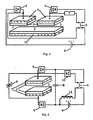
- Fig. 1 it is illustrated a device comprising of two equal flat conductive electrodes 1 (plates with an area S ), separated with to equal dielectric 2 layers (with a specific dielectric constant ⁇ d and total thickness d ) applied onto the electrodes.
- the plates can move relative to each other in a direction perpendicular to the plane of the plates, wherein a gap 3 thus formed between the dielectric layers is filled with air having a specific dielectric constant approximately equal to 1.
- ⁇ 0 is permittivity of vacuum, equal to 8.85 ⁇ 10 -12 F/m.
- the attraction force is equal to the ratio of an infinitesimal increment ⁇ W of the capacitor energy to the infinitesimal increment ⁇ x , i.e. the derivative of the energy according to x coordinate (this is a simple consequence of the energy conservation law: the work of the external force is fully used for the capacitor electrostatic energy change).
- the equation for the attraction force (3) can be obtained directly as a product of the charge at one of the plates Q and the resulting electric field intensity E, which influences the charge and equals to the sum of the electric field intensity produced by a charge at the other electrode, and the intensity produced by the electric polarization vector of the dielectric.
- the power supply e.g., battery
- the attraction force between the ESL electrodes essentially depends on the stability of the charges at the electrodes: any possibility of a charge outflow from the electrodes, or the charge value variations caused by the transients that occur when charging electrodes, dramatically reduces the attraction force in the event of even very small (in comparison with the dielectric layer width) air gap between the electrodes.
- the factors creating the repulsive force between the electrodes, when the charges at the electrodes reduced to zero, are as follows: an elastic force opposing the electrostatic attraction force, deforming the electrodes and dielectric, which in this case are similar to a compressed spring; a magnetic Ampere force arising between symmetrically arranged electrodes, at the same time providing opposite currents of the same magnitude passing therethrough.
- Fig. 5 shows such repelling currents, equal to the rates (6) of the charges. These currents will fluctuate out of phase with the charge values and will take the maximum in absolute magnitude by the time when the charges at the electrodes equal to zero.
- the device of Fig. 1 can not perform its basic function - the fixation of electrodes. To achieve this technical effect and the efficient ESL operation it is necessary to exclude the currents, reverse to the ones of the electrodes being charged. It's enough to include electric valves (rectifiers) into the operating electrical ESL as devices having non-linear current-voltage characteristics: a minimal resistance in the forward direction and maximal possible otherwise.
- electric valves rectifiers
- a rectifier diode can be such a device.
- a pair of such valves (rectifiers) with a reference number 6 integrated in series with the electrodes and the power supply into the ESL circuit eliminates the reverse current and trap the charges at the electrodes, providing a constant attraction force therebetween according to Equation (3), and also serve as a filter that neutralizes transient oscillations occurred when the power source is turned on.
- Fig. 2 a pair of such valves (rectifiers) with a reference number 6 integrated in series with the electrodes and the power supply into the ESL circuit, eliminates the reverse current and trap the charges at the electrodes, providing a constant attraction force therebetween according to Equation (3), and also serve as a filter that neutralizes transient oscillations occurred when the power source is turned on.
- FIG. 2 shows a ESL guaranteeing the achievement of the desired technical effect, comprising two electrodes 1, a dielectric 2, applied to the electrodes, wherein the electrodes can be tightly adjoin each other with their sides covered with a dielectric providing no air gaps, and at least one of the electrodes may move relative to the other one forming a gap 3 therebetween; two electric valves (rectifiers) 6, each connected in series with its electrodes as close to the electrode so as to allow the electrodes to accumulate opposite electric charges and to exclude the possibility of reverse current; a switch (electric key) 5, closing the electrodes and the electric valves (rectifiers) into a single circuit with an electrical power supply 4 while the ESL is locked, and causing short-circuit of the electrodes (either through a branch resistance 7) in the other position when ESL is unlocked.
- Fig. 3 shows an ESL, besides the electrodes 1 chargeable directly from the electrical power supply (primary electrodes) further comprising a secondary electrode 12, separated from the primary electrodes with dielectric 2 layers tightly adjoined thereto at a fixed (locked) state of the ESL, so when the electric charges are accumulated on the primary electrodes the secondary charges induced (stimulated) by the primary charges electric fields on the primary electrodes are accumulated on the secondary electrode on its contact surface with the primary ones (through the dielectric); wherein the induced secondary charges are of opposite polarity with respect to the primary charges inducing them thus creating an electrostatic attraction force between the primary and secondary electrodes. Operation of such ESL is completely similar to that shown in Fig. 2 , and in many cases it is more convenient and easier.
- ESL operation ( Fig. 2 or Fig. 3 ) it is very important to include one of the electrodes into a turning pair (for example, by means of a ball coupling) thus enabling the electrode to make small turns for fine adjustment to the other electrode when locking ESL. Otherwise, the inevitable technical tolerances during the assembling of ESL elements will lead to fatal air gaps prohibit ESL from normal operation.
- the best embodiment of the invention must contain at least one of the electrodes included into the turning pair as described above.
- the best ESL embodiment according to be implemented should contain a dielectric suitable for a thin film to be produced thereof and having the greatest possible ratio ⁇ d / d compared with other materials.
- Fig. 4 illustrate this additional capacitor with the reference number 8.
- an impulse generator e.g., piezo generator
- an unstable voltage source e.g. solar-battery and thermocouple
- a capacitor capacitance is rather small compared to the closed electrode capacitance, it can be introduced into the circuit in parallel with the electrodes to be fixed, eliminating any electric valves (rectifiers).
- Fig. 4 shows said capacitor with reference number 9.
- said switched capacitor can be used for locking and unlocking the ESL: for locking with simultaneous connecting to the power supply the switched capacitor is turned into a position when the capacitance equals zero, while for unlocking with simultaneous disconnecting ESL from the power supply the capacitor is turned into a position when the capacitance is maximal.
- Fig. 4 shows an electrical circuit of such an ESL, further comprising an inductance coil 11 and an electric valve (rectifier) 10, each enhancing the electrostatic repulsion effect.
- the groups of symmetrical contacts each situated on its electrode symmetrically to the contact on the oppositely charged facing electrode it is attracted to (similar to the contacts of Fig. 5 ), so that in event of the electrodes being discharged when unlocking the ESL an extra Ampere force is created repulsing the facing electrodes (a force of interaction between the facing electrodes when being discharged), enhancing and accelerating the ESL unlocking; and the group of antisymmetrical contacts each situated on its electrode antisymmetrically to the contact on the oppositely charged facing electrode it is attracted to (similar to the contacts of Fig.
Landscapes
- Physics & Mathematics (AREA)
- Electromagnetism (AREA)
- Engineering & Computer Science (AREA)
- Mechanical Engineering (AREA)
- Micromachines (AREA)
- Electrotherapy Devices (AREA)
- Charge And Discharge Circuits For Batteries Or The Like (AREA)
- Jigs For Machine Tools (AREA)
- Elimination Of Static Electricity (AREA)
- Container, Conveyance, Adherence, Positioning, Of Wafer (AREA)
Applications Claiming Priority (2)
| Application Number | Priority Date | Filing Date | Title |
|---|---|---|---|
| RU2012152879/12A RU2519877C2 (ru) | 2012-12-10 | 2012-12-10 | Замок электростатический |
| PCT/RU2013/001086 WO2014092606A1 (ru) | 2012-12-10 | 2013-12-03 | Замок электростатический |
Publications (2)
| Publication Number | Publication Date |
|---|---|
| EP2930291A1 true EP2930291A1 (de) | 2015-10-14 |
| EP2930291A4 EP2930291A4 (de) | 2016-12-14 |
Family
ID=50032048
Family Applications (1)
| Application Number | Title | Priority Date | Filing Date |
|---|---|---|---|
| EP13863581.8A Withdrawn EP2930291A4 (de) | 2012-12-10 | 2013-12-03 | Elektrostatisches schloss |
Country Status (5)
| Country | Link |
|---|---|
| US (1) | US20150315817A1 (de) |
| EP (1) | EP2930291A4 (de) |
| EA (1) | EA028285B1 (de) |
| RU (1) | RU2519877C2 (de) |
| WO (1) | WO2014092606A1 (de) |
Families Citing this family (5)
| Publication number | Priority date | Publication date | Assignee | Title |
|---|---|---|---|---|
| EA201600547A1 (ru) * | 2014-01-22 | 2016-11-30 | Евгений Анатольевич ОБЖИРОВ | Замок электростатический |
| US10355624B2 (en) * | 2014-10-09 | 2019-07-16 | Carnegie Mellon University | Electrostatic clutch |
| RU2613376C2 (ru) * | 2015-07-13 | 2017-03-16 | Евгений Анатольевич Обжиров | Устройство для разделения элементов конструкций летательных аппаратов |
| RU2638506C1 (ru) * | 2016-10-13 | 2017-12-13 | Евгений Анатольевич Обжиров | Замок электростатический |
| US10892938B1 (en) * | 2019-07-31 | 2021-01-12 | Abb Power Grids Switzerland Ag | Autonomous semantic data discovery for distributed networked systems |
Family Cites Families (9)
| Publication number | Priority date | Publication date | Assignee | Title |
|---|---|---|---|---|
| DE3713653A1 (de) * | 1987-04-21 | 1988-11-17 | Zeiss Ikon Ag | Doppelschliesszylinder |
| JP3005972B2 (ja) * | 1992-05-19 | 2000-02-07 | 株式会社 セル・コーポレーション | 閾動作式半導体型静電力装置 |
| US5930105A (en) * | 1997-11-10 | 1999-07-27 | Ion Systems, Inc. | Method and apparatus for air ionization |
| AU2498699A (en) * | 1998-04-29 | 1999-11-11 | Trimec Securities Pty. Ltd. | Electronic cylinder lock and computer security security system for gaming achines |
| RU2158438C1 (ru) * | 1999-04-14 | 2000-10-27 | Нунупаров Мартын Сергеевич | Электростатические устройства для механической блокировки |
| US20050198904A1 (en) * | 2004-03-12 | 2005-09-15 | Browne Alan L. | Active seal assemblies for movable windows |
| RU2399736C1 (ru) * | 2009-01-14 | 2010-09-20 | Мартын Сергеевич Нунупаров | Электронное устройство для механической блокировки |
| US8325458B2 (en) * | 2010-02-10 | 2012-12-04 | Sri International | Electroadhesive gripping |
| US9412547B2 (en) * | 2011-12-21 | 2016-08-09 | Siemens Aktiengesellschaft | Contactor |
-
2012
- 2012-12-10 RU RU2012152879/12A patent/RU2519877C2/ru not_active IP Right Cessation
-
2013
- 2013-12-03 US US14/650,582 patent/US20150315817A1/en not_active Abandoned
- 2013-12-03 EP EP13863581.8A patent/EP2930291A4/de not_active Withdrawn
- 2013-12-03 EA EA201500613A patent/EA028285B1/ru not_active IP Right Cessation
- 2013-12-03 WO PCT/RU2013/001086 patent/WO2014092606A1/ru not_active Ceased
Also Published As
| Publication number | Publication date |
|---|---|
| RU2519877C2 (ru) | 2014-06-20 |
| EA028285B1 (ru) | 2017-10-31 |
| RU2012152879A (ru) | 2014-02-10 |
| EA201500613A1 (ru) | 2015-09-30 |
| WO2014092606A1 (ru) | 2014-06-19 |
| US20150315817A1 (en) | 2015-11-05 |
| EP2930291A4 (de) | 2016-12-14 |
Similar Documents
| Publication | Publication Date | Title |
|---|---|---|
| US20150315817A1 (en) | Electrostatic lock | |
| Liang et al. | Synchronized triple bias-flip interface circuit for piezoelectric energy harvesting enhancement | |
| CN108667338B (zh) | 一种摩擦纳米发电机的能量管理电路和能量管理方法 | |
| US20140175941A1 (en) | Variable capacitive electrostatic machinery with macro pressure-gap product | |
| KR20090084828A (ko) | 전기 발전기 | |
| CN110176872B (zh) | 纳米发电机系统及供电器件 | |
| US10056848B2 (en) | Axially gapped electrostatic machine having drive structure configured to recycle charge | |
| WO2004017486A1 (en) | Battery charger | |
| Liu et al. | Sandwich structured electrostatic/electrets parallel-plate power generator for low acceleration and low frequency vibration energy harvesting | |
| US9935208B2 (en) | Energy storage device with large charge separation | |
| JP2019121687A (ja) | 光電変換素子、光センサ、発電装置、及び光電変換方法 | |
| Shih et al. | A non-contact mechanical solution for implementing synchronized switching techniques for energy harvesting using reed switches | |
| RU129134U1 (ru) | Замок электростатический | |
| EP2780925B1 (de) | Schütz | |
| CN101622683B (zh) | 双稳态电磁促动器,双线圈电磁促动器的控制电路和包括该控制电路的双线圈电磁促动器 | |
| Augustin et al. | System design of fast actuator for vacuum interrupter in DC applications | |
| EP1676353A1 (de) | Feldkraftmaschine | |
| RU2592356C1 (ru) | Замок электростатический | |
| Balkanski | Solid state micropower | |
| Fetisov | Magnetoelectric effect in multilayer ferromagnetic-piezoelectric structures and its application in electronics | |
| CN1564290A (zh) | 永磁式双稳态接触器 | |
| Boisseau et al. | Stable DRIE-patterned SiO 2/Si 3 N 4 electrets | |
| US20240258438A1 (en) | Semiconductor diode | |
| Chen et al. | An approach with electrostatic MEMS switch for environment energy harvesting | |
| RU2485614C2 (ru) | Индукционно-динамический привод |
Legal Events
| Date | Code | Title | Description |
|---|---|---|---|
| PUAI | Public reference made under article 153(3) epc to a published international application that has entered the european phase |
Free format text: ORIGINAL CODE: 0009012 |
|
| 17P | Request for examination filed |
Effective date: 20150709 |
|
| AK | Designated contracting states |
Kind code of ref document: A1 Designated state(s): AL AT BE BG CH CY CZ DE DK EE ES FI FR GB GR HR HU IE IS IT LI LT LU LV MC MK MT NL NO PL PT RO RS SE SI SK SM TR |
|
| AX | Request for extension of the european patent |
Extension state: BA ME |
|
| DAX | Request for extension of the european patent (deleted) | ||
| RA4 | Supplementary search report drawn up and despatched (corrected) |
Effective date: 20161110 |
|
| RIC1 | Information provided on ipc code assigned before grant |
Ipc: E05C 19/16 20060101ALI20161104BHEP Ipc: H02N 13/00 20060101ALI20161104BHEP Ipc: E05B 47/00 20060101AFI20161104BHEP |
|
| STAA | Information on the status of an ep patent application or granted ep patent |
Free format text: STATUS: THE APPLICATION IS DEEMED TO BE WITHDRAWN |
|
| 18D | Application deemed to be withdrawn |
Effective date: 20170610 |