EP2930270B1 - Damper device - Google Patents
Damper device Download PDFInfo
- Publication number
- EP2930270B1 EP2930270B1 EP14164376.7A EP14164376A EP2930270B1 EP 2930270 B1 EP2930270 B1 EP 2930270B1 EP 14164376 A EP14164376 A EP 14164376A EP 2930270 B1 EP2930270 B1 EP 2930270B1
- Authority
- EP
- European Patent Office
- Prior art keywords
- cylinder
- charger
- bulkhead
- piston
- piston rod
- Prior art date
- Legal status (The legal status is an assumption and is not a legal conclusion. Google has not performed a legal analysis and makes no representation as to the accuracy of the status listed.)
- Active
Links
- 239000007788 liquid Substances 0.000 claims description 33
- 239000000463 material Substances 0.000 claims description 20
- 229920001296 polysiloxane Polymers 0.000 claims description 4
- 238000003032 molecular docking Methods 0.000 description 18
- 238000013016 damping Methods 0.000 description 14
- 239000012530 fluid Substances 0.000 description 10
- 238000007667 floating Methods 0.000 description 5
- 230000006835 compression Effects 0.000 description 4
- 238000007906 compression Methods 0.000 description 4
- 238000003780 insertion Methods 0.000 description 4
- 230000037431 insertion Effects 0.000 description 4
- 230000000712 assembly Effects 0.000 description 3
- 238000000429 assembly Methods 0.000 description 3
- 238000006073 displacement reaction Methods 0.000 description 3
- 238000009434 installation Methods 0.000 description 3
- 238000005192 partition Methods 0.000 description 3
- 238000010276 construction Methods 0.000 description 2
- 230000001419 dependent effect Effects 0.000 description 2
- 238000010586 diagram Methods 0.000 description 2
- 230000000694 effects Effects 0.000 description 2
- 238000012423 maintenance Methods 0.000 description 2
- 230000008929 regeneration Effects 0.000 description 2
- 238000011069 regeneration method Methods 0.000 description 2
- 238000007789 sealing Methods 0.000 description 2
- 238000009423 ventilation Methods 0.000 description 2
- 230000001133 acceleration Effects 0.000 description 1
- 238000013459 approach Methods 0.000 description 1
- 230000000903 blocking effect Effects 0.000 description 1
- 230000037237 body shape Effects 0.000 description 1
- 238000004891 communication Methods 0.000 description 1
- 230000000994 depressogenic effect Effects 0.000 description 1
- 238000013461 design Methods 0.000 description 1
- 238000011161 development Methods 0.000 description 1
- 230000018109 developmental process Effects 0.000 description 1
- 238000004519 manufacturing process Methods 0.000 description 1
- 238000000034 method Methods 0.000 description 1
- 230000008092 positive effect Effects 0.000 description 1
- 230000036316 preload Effects 0.000 description 1
- 238000003825 pressing Methods 0.000 description 1
- 230000001105 regulatory effect Effects 0.000 description 1
- 230000002040 relaxant effect Effects 0.000 description 1
- 238000003860 storage Methods 0.000 description 1
Images


Classifications
-
- F—MECHANICAL ENGINEERING; LIGHTING; HEATING; WEAPONS; BLASTING
- F16—ENGINEERING ELEMENTS AND UNITS; GENERAL MEASURES FOR PRODUCING AND MAINTAINING EFFECTIVE FUNCTIONING OF MACHINES OR INSTALLATIONS; THERMAL INSULATION IN GENERAL
- F16F—SPRINGS; SHOCK-ABSORBERS; MEANS FOR DAMPING VIBRATION
- F16F9/00—Springs, vibration-dampers, shock-absorbers, or similarly-constructed movement-dampers using a fluid or the equivalent as damping medium
- F16F9/30—Springs, vibration-dampers, shock-absorbers, or similarly-constructed movement-dampers using a fluid or the equivalent as damping medium with solid or semi-solid material, e.g. pasty masses, as damping medium
-
- F—MECHANICAL ENGINEERING; LIGHTING; HEATING; WEAPONS; BLASTING
- F16—ENGINEERING ELEMENTS AND UNITS; GENERAL MEASURES FOR PRODUCING AND MAINTAINING EFFECTIVE FUNCTIONING OF MACHINES OR INSTALLATIONS; THERMAL INSULATION IN GENERAL
- F16F—SPRINGS; SHOCK-ABSORBERS; MEANS FOR DAMPING VIBRATION
- F16F9/00—Springs, vibration-dampers, shock-absorbers, or similarly-constructed movement-dampers using a fluid or the equivalent as damping medium
- F16F9/32—Details
- F16F9/50—Special means providing automatic damping adjustment, i.e. self-adjustment of damping by particular sliding movements of a valve element, other than flexions or displacement of valve discs; Special means providing self-adjustment of spring characteristics
- F16F9/52—Special means providing automatic damping adjustment, i.e. self-adjustment of damping by particular sliding movements of a valve element, other than flexions or displacement of valve discs; Special means providing self-adjustment of spring characteristics in case of change of temperature
-
- E—FIXED CONSTRUCTIONS
- E01—CONSTRUCTION OF ROADS, RAILWAYS, OR BRIDGES
- E01C—CONSTRUCTION OF, OR SURFACES FOR, ROADS, SPORTS GROUNDS, OR THE LIKE; MACHINES OR AUXILIARY TOOLS FOR CONSTRUCTION OR REPAIR
- E01C19/00—Machines, tools or auxiliary devices for preparing or distributing paving materials, for working the placed materials, or for forming, consolidating, or finishing the paving
- E01C19/48—Machines, tools or auxiliary devices for preparing or distributing paving materials, for working the placed materials, or for forming, consolidating, or finishing the paving for laying-down the materials and consolidating them, or finishing the surface, e.g. slip forms therefor, forming kerbs or gutters in a continuous operation in situ
-
- F—MECHANICAL ENGINEERING; LIGHTING; HEATING; WEAPONS; BLASTING
- F16—ENGINEERING ELEMENTS AND UNITS; GENERAL MEASURES FOR PRODUCING AND MAINTAINING EFFECTIVE FUNCTIONING OF MACHINES OR INSTALLATIONS; THERMAL INSULATION IN GENERAL
- F16F—SPRINGS; SHOCK-ABSORBERS; MEANS FOR DAMPING VIBRATION
- F16F9/00—Springs, vibration-dampers, shock-absorbers, or similarly-constructed movement-dampers using a fluid or the equivalent as damping medium
- F16F9/02—Springs, vibration-dampers, shock-absorbers, or similarly-constructed movement-dampers using a fluid or the equivalent as damping medium using gas only or vacuum
- F16F9/0209—Telescopic
-
- F—MECHANICAL ENGINEERING; LIGHTING; HEATING; WEAPONS; BLASTING
- F16—ENGINEERING ELEMENTS AND UNITS; GENERAL MEASURES FOR PRODUCING AND MAINTAINING EFFECTIVE FUNCTIONING OF MACHINES OR INSTALLATIONS; THERMAL INSULATION IN GENERAL
- F16F—SPRINGS; SHOCK-ABSORBERS; MEANS FOR DAMPING VIBRATION
- F16F9/00—Springs, vibration-dampers, shock-absorbers, or similarly-constructed movement-dampers using a fluid or the equivalent as damping medium
- F16F9/10—Springs, vibration-dampers, shock-absorbers, or similarly-constructed movement-dampers using a fluid or the equivalent as damping medium using liquid only; using a fluid of which the nature is immaterial
- F16F9/14—Devices with one or more members, e.g. pistons, vanes, moving to and fro in chambers and using throttling effect
- F16F9/16—Devices with one or more members, e.g. pistons, vanes, moving to and fro in chambers and using throttling effect involving only straight-line movement of the effective parts
- F16F9/18—Devices with one or more members, e.g. pistons, vanes, moving to and fro in chambers and using throttling effect involving only straight-line movement of the effective parts with a closed cylinder and a piston separating two or more working spaces therein
- F16F9/19—Devices with one or more members, e.g. pistons, vanes, moving to and fro in chambers and using throttling effect involving only straight-line movement of the effective parts with a closed cylinder and a piston separating two or more working spaces therein with a single cylinder and of single-tube type
-
- F—MECHANICAL ENGINEERING; LIGHTING; HEATING; WEAPONS; BLASTING
- F16—ENGINEERING ELEMENTS AND UNITS; GENERAL MEASURES FOR PRODUCING AND MAINTAINING EFFECTIVE FUNCTIONING OF MACHINES OR INSTALLATIONS; THERMAL INSULATION IN GENERAL
- F16F—SPRINGS; SHOCK-ABSORBERS; MEANS FOR DAMPING VIBRATION
- F16F9/00—Springs, vibration-dampers, shock-absorbers, or similarly-constructed movement-dampers using a fluid or the equivalent as damping medium
- F16F9/32—Details
-
- E—FIXED CONSTRUCTIONS
- E01—CONSTRUCTION OF ROADS, RAILWAYS, OR BRIDGES
- E01C—CONSTRUCTION OF, OR SURFACES FOR, ROADS, SPORTS GROUNDS, OR THE LIKE; MACHINES OR AUXILIARY TOOLS FOR CONSTRUCTION OR REPAIR
- E01C2301/00—Machine characteristics, parts or accessories not otherwise provided for
- E01C2301/02—Feeding devices for pavers
- E01C2301/04—Independent shuttles
-
- E—FIXED CONSTRUCTIONS
- E01—CONSTRUCTION OF ROADS, RAILWAYS, OR BRIDGES
- E01C—CONSTRUCTION OF, OR SURFACES FOR, ROADS, SPORTS GROUNDS, OR THE LIKE; MACHINES OR AUXILIARY TOOLS FOR CONSTRUCTION OR REPAIR
- E01C2301/00—Machine characteristics, parts or accessories not otherwise provided for
- E01C2301/02—Feeding devices for pavers
- E01C2301/08—Pushing devices for lorries
Definitions
- the invention relates to a damper device according to the preamble of claim 1.
- the truck docks for loading on an impression beam of the paver or feeder in order to position its loading surface above the material bunker so that no material drops next to it during tipping. So that the paver or loader during docking of the truck, or when pushing the truck, not jerky on the ground is offset backwards, the impression beam is conventionally mounted resiliently or damping.
- the DE 10 2011 120 161 A1 a paver with a docking assembly, which is seen below seen in the direction of travel below the material bunker.
- the docking assembly comprises an impression beam, which is resiliently mounted by means of elastomeric structure dampers.
- the disadvantage of this is that the elastomeric structure damper harden over time and become brittle, which in particular undesirably changes the damping characteristic of the pressure assembly.
- US 5,004,394 A and EP 2 295 641 A2 each discloses a paver with a docking assembly, wherein the docking beam of the docking assembly is supported by two controllable hydraulic cylinders.
- the respective hydraulic cylinders are connected on opposite sides of the piston to a provided in the paver hydraulic system.
- the respective pistons of the hydraulic cylinders can thus be adjusted between a retracted and an extended position by introducing a hydraulic fluid from outside into the hydraulic cylinders.
- Disadvantageous is that the connection of the respective hydraulic cylinder to the hydraulic system of the paver is expensive and the hydraulic lines, which are connected to the hydraulic cylinder, take up much space on the paver. Further, to drive the hydraulic system to place the respective hydraulic cylinders in a desired position, additional electronic components are required on the paver, thereby increasing the manufacturing cost.
- DE 2 243 076 A discloses a bumper for motor vehicles.
- the bumper has a first and second damper, which are interconnected crosswise by means of hydraulic lines, so that from the first damper from a piston rod side hydraulic fluid in the piston side of the second damper and from the piston side of the first damper hydraulic fluid in the piston rod side of the second damper is displaceable.
- the respective dampers further comprise a separating piston, which delimits a gas space in the damper, which serves to compensate for a change in volume.
- the respective dampers are further connected to a regeneration system, which supplies the dampers from the outside a hydraulic fluid to reset the damper after an impact in a starting position.
- the disadvantage of this is that much space in the motor vehicle is claimed by connecting the dampers to each other and the connection of the respective damper to the hydraulic regeneration system and continue to be a high maintenance and service needs.
- EP 1 734 276 A2 discloses a gas spring with a return space in which a compression spring is arranged.
- the compression spring may be formed as Tellerfederpacket.
- the restoring space is separated by a cup-shaped balance piston from an interior of a working cylinder.
- GB 2 308 421 A discloses a gas spring with a working piston which divides a closed cylinder into a first chamber and into a second chamber and is arranged displaceably between them. At the bottom of the gas spring, a compensation chamber is provided, which is separated from a working chamber of the gas spring by a displaceably mounted piston.
- US 2013/0322965 A1 discloses a paver with a docking device.
- the docking device includes an adjustment member having a hydraulic cylinder that may be activated by a controller to displace a pressure beam relative to a chassis support to align a material delivery vehicle pushed by the docking device in a desired position relative to the paver.
- EP 2 527 534 A1 discloses a paver with an impression beam carried by a damper.
- the damper has a friction spring, which has a different damping rate during compression than rebound.
- the invention is therefore an object of the invention to provide a paver or a feeder available, which can push through the use of simple, constructive technical means a heavy material supply vehicle during installation before him, without causing unwanted accelerations act on the paver, which the quality of the installation result could be reduced.
- the closed chamber has a variable volume to compensate for temperature-induced pressure fluctuations within the closed chamber, ie the closed chamber is adapted to accommodate a temperature increase or decrease in volume of the compressible liquid enclosed therein, thus providing almost a constant force characteristic (Dämpf nomizing) can be achieved regardless of the temperature of the trapped liquid for the damper device.
- the damper device according to the invention has the advantage that it is compact and thus ideal for use on vehicles, especially on self-propelled construction machinery, for example on a paver or a feeder, can be used. This is mainly because the damper device according to the invention is a self-contained damping system, which does not have to be additionally connected to a hydraulic system.
- the compressible liquid always remains in the closed chamber; that is, the closed chamber is not in communication with an external hydraulic system.
- the damping effect can be achieved by the connected to the hydraulic cylinder hydraulic system, for example by throttle elements, the damper device according to the invention allows the damping effect itself. Therefore, the damper device according to the invention can in particular inexpensively retrofit to a paver or on a feeder or from this for maintenance and service purposes.
- the ground unit has a bulkhead which is displaceably arranged inside the cylinder.
- the variable volume of the closed chamber is directly related to the position of the bulkhead within the cylinder.
- the bulkhead provides a simple means for compensating for a pressure change of the compressible fluid trapped in the chamber, whether by retraction of the piston rod and / or by a temperature-induced volume change of the fluid, by further pushing it into the cylinder, to the volume to increase the closed chamber, or shifts in the direction of the piston bearing to reduce the volume of the closed chamber.
- the base unit comprises a cover and a spring element, wherein the spring element is arranged between the cover and the bulkhead.
- the bulkhead comprises an end section and a guide section, wherein the guide section has a larger outer diameter than the end section. This allows the end portion to sit in a particularly stable manner on the spring element of the ground unit.
- the spring element at least partially surrounds the end portion of the bulkhead to stably support the bulkhead within the cylinder.
- the bulkhead wall between the end portion and the guide portion provides a seat against which rests the spring element. This ensures that the bulkhead can be stably guided by the spring element in a linear direction within the cylinder.
- the spring element comprises at least one plate spring.
- the plate spring can absorb very large forces, it only needs a small installation space.
- the spring element comprises a plurality of disc springs to form a spring column.
- the spring column may have individual oppositely disposed disc springs and / or a plurality of oppositely arranged spring assemblies, each comprising a plurality of superposed in the same direction disc springs, to provide a greater spring distance available, or to provide a desired spring rate.
- the bulkhead is rotatably mounted relative to the cylinder. That is, the bulkhead within the cylinder is linearly displaceable but can not rotate relative to the cylinder. This can be made possible for example by a guide, along which the bulkhead is linearly displaceable within the cylinder. As such guidance could be provided, for example, between the cylinder and the bulkhead a NutfederNK.
- the bulkhead is concave towards the interior of the chamber, that is, formed as a hollow body, which is a part of the chamber volume of the damper device forms. It is thus possible to provide the largest possible damping volume for the closed chamber, without enlarging the damper device.
- the accommodated in the hollow body compressible fluid also ensures in an advantageous manner that the partition wall formed as a hollow body is uniformly displaceable within the cylinder, even if large forces act on the piston rod.
- the hollow body shape of the bulkhead favors the sealing of the closed chamber relative to the ground unit because the compressible liquid presses against the inner surface of the hollow body outwardly against the cylinder.
- a piston plate is mounted within the cylinder between the piston bearing and the bottom unit on the piston rod.
- the piston plate forms a displaceable partition wall between the two chamber halves and preferably has at least one throttle bore in order to ensure a displacement of the compressible fluid between the two chamber halves, when the piston rod shifts relative to the cylinder.
- the retraction or restoring behavior of the piston rod can be adjusted precisely in particular by a valve element being arranged in at least one of the throttle bores.
- a valve element being arranged in at least one of the throttle bores.
- this is a ball check valve which opens and thereby ensures a flow through the compressible fluid when the piston rod enters the cylinder, or which closes when the piston rod automatically returns from a retracted position to the starting position.
- the damping property of the damper device can be perfectly regulated in the desired manner.
- the damper device can be used in particular for damping large forces and for use with relatively large temperature fluctuations when the compressible liquid is a silicone.
- a silicone offers excellent elastic compression properties and can be easily moved between the two chambers, if on the piston rod acts a push-in force, or is taken away from this.
- the silicone requires that the piston rod automatically returns to its original position as soon as the force acting on the piston rod falls below a predetermined threshold of force.
- an impression beam of a paver or feeder carried by the piston rod can automatically, i. without additional hydraulic control effort, be reset to its original position when it is depressed by a pressing force, i.e., when the truck leaves after the load.
- the cylinder and / or the floor unit comprises a ventilation opening, through which air can be displaced or flowed out of / into the floor unit when the partition wall shifts. This implies that no air is trapped in the ground unit and forms an air cushion which affects the damping characteristic.
- the damper device according to the invention can be used excellently in a paver or feeder. It is in particular a paver or feeder comprising a material bunker and at least one damper device according to the invention, which is attached to the chassis of the paver or feeder and carries an impression beam, against which a material delivery vehicle can dock for filling the material bunker.
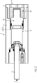
- FIG. 1 shows a damper device 1 according to the invention as a sectional view.
- the damper device 1 has a cylinder 2, at one end of which a piston bearing 3 with a piston rod 4 arranged displaceably therein is fastened.
- a bottom unit 5 is attached on the other side of the cylinder 2.
- the cylinder 2 forms together with the piston bearing 3 and the bottom unit 5 a closed chamber 6, in which a compressible liquid 7 is enclosed.
- a piston plate 8 is fixed.
- the first chamber half 9 is located on a side facing away from the piston bearing 3 side of the piston plate 8.
- the second chamber half 10 of the closed chamber 6 is on a side facing the piston bearing 3 side of the piston plate 8.
- the piston rod 4 in an initial position in which it rests against the piston bearing 3. In the starting position, almost all of the compressible liquid 7 is in the first chamber half 9.
- the piston plate 8 has two throttle bores 11, wherein in one of the throttle bores 11, a check valve 12 is arranged. It is thereby achieved that upon insertion of the piston rod 4 into the cylinder 2, the compressible liquid 7 flows through both throttle bores 11 from the first chamber half 9 into the second chamber half 10. In this case, the pressure within the closed chamber 6 increases. Once an applied to the piston rod 4 insertion force F, which acts on the inserted piston rod 4, is removed, the piston rod 4 is automatically in accordance with the FIG. 1 set back starting position shown. The pressure within the closed chamber 6 falls back to the original pressure potential in the starting position.
- a filling opening 13 is formed in the piston bearing 3.
- a valve element 14 in particular a one-way valve, is provided for filling or enclosing the compressible liquid 7 in the closed chamber 6.
- a piston plate seal 15 is attached.
- the piston plate seal 15 requires that the compressible liquid 7 flows between the two chamber halves 9, 10 only through the throttle bores 11 back and forth, when the piston rod 4 is displaced within the cylinder 2.
- the damper device according to the invention has FIG. 1 a screw-threaded connection 16, by means of which the piston bearing 3 is attached to the cylinder 2.
- the piston bearing 3 is formed integrally with the cylinder 2.
- the bottom unit 5 comprises a cover 17, a spring element 18 and a bulkhead 19.
- the bulkhead 19 is arranged floating in the cylinder 2 and forms a displaceable chamber boundary of the closed chamber 6.
- the cover 17 comprises a guide projection 20, which by means of a further ringenGewinde connection 21 is attached to the cylinder 2.
- the spring element 18 comprises a plurality of individual disc springs 22. As shown, these can be arranged individually, or as spring assemblies, comprising two, three or more disk springs arranged in the same direction in opposite directions to one another. As a result, the damping or spring characteristic of the spring element 18 can be adjusted well.
- the disc springs 22 are particularly suitable for damping large forces and have a temperature-dependent damping characteristic.
- the bulkhead 19 has a guide portion 23 and an end portion 24. Between the guide portion 23 and the end portion 24, a seat 25 is formed, which bears against the spring element 18. For improved storage of the bulkhead 19 on the spring element 18, this is arranged around the end portion 24 around. Furthermore, one can in the FIG. 1 clearly see that the spring element 18 between the end portion 24 of the bulkhead 19 and the guide projection 20 of the lid 17 is arranged, whereby a guide for the spring element 18 is provided, within which the spring element 18 can compress or relax purposefully.
- the bulkhead 19 also has at least one sealing element 27, which ensures that the compressible liquid 7 remains in the closed chamber 6.
- a guide member 28 is provided between the cylinder 2 and the bulkhead 19.
- the guide element 28 may be formed for example by a spring-groove connection.
- a ventilation opening 29 is formed in the lid 17 according to FIG. 1 .
- the vent opening 29 allows air to flow into and out of the space in which the spring element 18 is located when the bulkhead 19 is reciprocated in the cylinder 2.
- at least one mounting opening 30a is formed in the cover 17, in which a tool (not shown) can engage in order to screw the cover 17 onto the cylinder 2.
- FIG. 1 is the temperature of the compressible liquid 7 + 20 ° C.
- the spring element 18 is completely relaxed. In the relaxed state, the spring element 18 holds the bulkhead 19 in an end position in which the bulkhead 19 at an optional provided projection 29a of the cylinder 2 is applied.
- the piston rod 4 abuts against the piston bearing 3.
- FIG. 2 is the bulkhead 19 from its end position according to FIG. 1 positioned out in a zero position.
- the bulkhead 19 is offset by a spring travel X to the right to the cover 17 of the bottom unit 5 back.
- the zero position is achieved by the enclosed in the chamber 6 compressible fluid 7 exerts a predetermined pressure, which ensures at the same time that the piston rod 4 is biased in the initial position on the piston bearing 3.
- the spring travel X is 6 mm when the spring element 18 is biased at 61.2 bar, which corresponds approximately to a force F on the piston rod 4 of 300 daN and 2700 daN on the bulkhead 19.
- the volume of the chamber 6 increases by about 26.56 cm 3 to about 564.56 cm 3 , when the liquid temperature remains at + 20 ° C.
- FIG. 3 shows the damper device 1 in a highly loaded state.
- the piston rod 4 is completely, for example 80 mm, inserted into the cylinder 2. This is achieved by acting on the piston rod 4, a force F of about 6500 daN.
- the bulkhead 19 is pressed by a maximum spring deflection Y against the biasing force of the spring element 18 to the cover 17 of the bottom unit 5 through. In this position, the spring element 18 is charged to about 80%.
- the liquid temperature is still + 20 ° C.
- the damper device 1 leads in the FIG. 4 a temperature-related volume compensation.
- the damper device 1 of the invention takes into account a temperature drop of -30 ° C, so that the liquid temperature of originally + 20 ° C according to the FIG. 2 cooled to -10 ° C.
- the bulkhead 19 is therefore made of the material described in US Pat FIG. 2 shown zero position out by the biasing force of the spring member 18 to the left in the direction of the piston rod 4 out to adjust the volume of the chamber 6 of the shrinkage of the compressible liquid 7. How good in the FIG. 4 can be seen, the bulkhead 19 is then back to the projection 29 a of the cylinder.
- the according to the FIG. 2 acting prestressing force of 300 daN is reduced by the volume compensation, ie by relaxing the spring element 18, to about 125 daN.
- the damper device 1 according to the invention according to the FIG. 5 performs a volume balance of the closed chamber 6 at a temperature rise. This again takes place relative to the zero position of the bulkhead 19 according to FIG FIG. 2 , In the figure 5, the spring element 18 is biased by a force F of 300 daN. At a temperature rise of + 30 ° C, the original increases in FIG. 2 assumed liquid temperature of + 20 ° C to + 50 ° C, whereby the biasing force F increases to the spring element 18 to about 400 daN. The spring element 18 is loaded to about 40%.
- the bulkhead 19 of the damper device according to the invention can compensate for a temperature-induced shrinkage or expansion of the compressible liquid 7, because it is arranged floating within the cylinder. This can take place independently of the position of the piston rod 4 within the cylinder 2 in the damper device 1 according to the invention.
- the bulkhead 19 is formed as a concave or hollow body 30.
- the hollow body 30 thus forms part of the volume of the enclosed chamber 6. Because the pressure spreads evenly on the inner surface of the hollow body 30, the seal between the hollow body 30 and the cylinder 2 improves.
- the provision of the hollow body 30 increases As a result, a larger amount of compressible liquid 7 can be accommodated in the closed chamber 6, which can have a positive effect on the shrinkage or expansion behavior of the liquid 7.
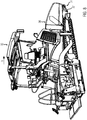
- FIG. 7 shows a docking assembly 31, which on a paver 35 according to the FIG. 8 or on a feeder 38 according to the FIG. 9 can be attached.
- the docking assembly 31 comprises an impression beam 32 on which impression rollers 33 are rotatably mounted. The impression rollers 33 can during the loading of a preceding Lug truck to push this before the feeder 38 and before the paver 35.
- the docking assembly 31 further comprises a crossbar 34 attachable to the chassis to which two of the damper devices 1 of the invention are attached.
- the respective piston rods 4 are attached to the impression beam 32. According to the forces acting on the impression beam 32, the damper devices 1 can be moved in and out independently of one another.
- the crossbar 34 which according to the FIG. 7 is present as part of the docking 31, could just as well be designed as a chassis component of the paver 35 or feeder 38, wherein the respective damper devices 1 can be detachably attached thereto.
- FIG. 8 shows a paver 35 with a material bunker 36 and a chassis 37.
- the docking assembly 31 is mounted on the chassis 37 and protrudes seen in the direction of travel V front below the material bunker 36 over a predetermined length protrudes to dock against the rear tires of a preceding truck, when this Material feed to the paver 35 approaches.
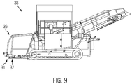
- FIG. 9 shows a feeder 38.
- the feeder 38 also has a material bunker 36 as the paver 35.
- On the chassis 37 of the feeder 38 is the front below the material bunker 36 in the FIG. 7 shown docking assembly 31 is fixed to dock against the rear tires of a preceding truck.
- FIG. 10 shows a force-displacement diagram for the damper device according to the invention 1.
- the spring element 18 comprised eleven pieces of disc springs (70 x 35.5 x 4), once three springs and three times two springs were arranged as mutually identical spring assemblies and twice a spring mutually alternating. With a completely tensioned spring column, a maximum spring preload force of 9273 daN is established.
- the damper device 1 according to the invention was tested at temperatures of -10.degree. C., 0.degree. C., + 8.degree.
- the linear force path characteristics according to FIG. 10 behave substantially similar despite the widely varying temperatures of the trapped liquid 7, which is caused by the bulkhead 19 floating in the cylinder 2.
- the damper device 1 according to the invention maintains a nearly constant damping characteristic even when used in different temperature situations, so that there in particular the charge of a road paver 35 and a feeder 38 according to the FIGS. 8 and 9 improved feasible.
Landscapes
- Engineering & Computer Science (AREA)
- General Engineering & Computer Science (AREA)
- Mechanical Engineering (AREA)
- Architecture (AREA)
- Civil Engineering (AREA)
- Structural Engineering (AREA)
- Fluid-Damping Devices (AREA)
- Road Paving Machines (AREA)
Description
Die Erfindung bezieht sich auf eine Dämpfervorrichtung gemäß dem Oberbegriff des Anspruchs 1.The invention relates to a damper device according to the preamble of
Aus der Praxis und beispielsweise aus der
Es ist ferner bekannt, dass der Lastkraftwagen zur Beschickung an einem Abdruckbalken des Straßenfertigers oder Beschickers andockt, um seine Ladefläche derart über dem Materialbunker zu positionieren, dass beim Abkippen kein Material daneben fällt. Damit der Straßenfertiger bzw. Beschicker während des Andockens des Lastkraftwagens, bzw. beim Anschieben des Lastkraftwagens, nicht ruckartig auf dem Untergrund rückwärts versetzt wird, ist der Abdruckbalken herkömmlicherweise federnd bzw. dämpfend gelagert.It is also known that the truck docks for loading on an impression beam of the paver or feeder in order to position its loading surface above the material bunker so that no material drops next to it during tipping. So that the paver or loader during docking of the truck, or when pushing the truck, not jerky on the ground is offset backwards, the impression beam is conventionally mounted resiliently or damping.
Beispielsweise offenbart die
Der Erfindung liegt daher die Aufgabe zugrunde, einen Straßenfertiger oder einen Beschicker zur Verfügung zu stellen, der durch den Einsatz einfacher, konstruktiver technischer Mittel ein schweres Materialversorgungsfahrzeug während des Einbaus vor sich her schieben kann, ohne dass dadurch unerwünschte Beschleunigungen auf den Straßenfertiger wirken, wodurch die Qualität des Einbauergebnisses gemindert werden könnte.The invention is therefore an object of the invention to provide a paver or a feeder available, which can push through the use of simple, constructive technical means a heavy material supply vehicle during installation before him, without causing unwanted accelerations act on the paver, which the quality of the installation result could be reduced.
Diese Aufgabe wird gelöst durch einen Straßenfertiger oder einen Beschicker den technischen Merkmalen des Anspruchs 1. Verbesserte Weiterbildungen der Erfindung sind Gegenstand der Unteransprüche.This object is achieved by a paver or a feeder the technical features of
Erfindungsgemäß hat die geschlossene Kammer ein veränderbares Volumen, um temperaturbedingte Druckschwankungen innerhalb der geschlossenen Kammer zu kompensieren D.h., dass die geschlossene Kammer dazu ausgebildet ist, sich einer temperaturbedingten Volumenzunahme bzw. Volumenabnahme der darin eingeschlossenen kompressiblen Flüssigkeit anzupassen, sodass auf diese Weise nahezu eine konstante Kraftkennlinie (Dämpfcharakteristik) unabhängig von der Temperatur der eingeschlossenen Flüssigkeit für die Dämpfervorrichtung erreicht werden kann. Darüber hinaus bietet die erfindungsgemäße Dämpfervorrichtung den Vorteil, dass sie kompakt herstellbar ist und somit ideal zum Einsatz an Fahrzeugen, insbesondere an selbstfahrenden Baumaschinen, beispielsweise an einem Straßenfertiger oder einem Beschicker, einsetzbar ist. Dies liegt vor allem daran, weil die erfindungsgemäße Dämpfervorrichtung ein in sich geschlossenes Dämpfsystem darstellt, welches nicht zusätzlich an einem Hydrauliksystem angeschlossen werden muss. Bei der Erfindung bleibt daher die kompressible Flüssigkeit stets in der geschlossenen Kammer; d.h., dass die geschlossene Kammer nicht in Verbindung mit einem externen Hydrauliksystem steht. Während bei bekannten Hydrauliksystemen, die Dämpfwirkung durch das an die Hydraulikzylinder angeschlossene Hydrauliksystem beispielsweise durch Drosselelemente, erzielbar ist, ermöglicht die erfindungsgemäße Dämpfervorrichtung die Dämpfwirkung selbst. Daher lässt sich die erfindungsgemäße Dämpfervorrichtung insbesondere kostengünstig an einem Straßenfertiger bzw. an einem Beschicker nachrüsten bzw. von diesem für Wartungs- und Servicezwecke entfernen.According to the invention, the closed chamber has a variable volume to compensate for temperature-induced pressure fluctuations within the closed chamber, ie the closed chamber is adapted to accommodate a temperature increase or decrease in volume of the compressible liquid enclosed therein, thus providing almost a constant force characteristic (Dämpfcharakteristik) can be achieved regardless of the temperature of the trapped liquid for the damper device. In addition, the damper device according to the invention has the advantage that it is compact and thus ideal for use on vehicles, especially on self-propelled construction machinery, for example on a paver or a feeder, can be used. This is mainly because the damper device according to the invention is a self-contained damping system, which does not have to be additionally connected to a hydraulic system. In the invention, therefore, the compressible liquid always remains in the closed chamber; that is, the closed chamber is not in communication with an external hydraulic system. While in known hydraulic systems, the damping effect can be achieved by the connected to the hydraulic cylinder hydraulic system, for example by throttle elements, the damper device according to the invention allows the damping effect itself. Therefore, the damper device according to the invention can in particular inexpensively retrofit to a paver or on a feeder or from this for maintenance and service purposes.
Erfindungsgemäß verfügt die Bodeneinheit über eine Schottwand, die innerhalb des Zylinders verschiebbar angeordnet ist. Bei dieser Ausführungsform hängt damit das veränderbare Volumen der geschlossenen Kammer direkt mit der Lage der Schottwand innerhalb des Zylinders zusammen. Die Schottwand bietet ein einfaches Mittel, um eine Druckänderung der in der Kammer eingeschlossenen kompressiblen Flüssigkeit, sei es durch das Einfahren der Kolbenstange und/oder durch eine temperaturbedingte Volumenänderung der Flüssigkeit, zu kompensieren, indem sie in den Zylinder weiter eingedrückt wird, um das Volumen der geschlossenen Kammer zu vergrößern, oder sich in Richtung des Kolbenlagers verschiebt, um das Volumen der geschlossenen Kammer zu verkleinern.According to the invention, the ground unit has a bulkhead which is displaceably arranged inside the cylinder. In this embodiment, therefore, the variable volume of the closed chamber is directly related to the position of the bulkhead within the cylinder. The bulkhead provides a simple means for compensating for a pressure change of the compressible fluid trapped in the chamber, whether by retraction of the piston rod and / or by a temperature-induced volume change of the fluid, by further pushing it into the cylinder, to the volume to increase the closed chamber, or shifts in the direction of the piston bearing to reduce the volume of the closed chamber.
Erfindungsgemäß umfasst die Bodeneinheit einen Deckel und ein Federelement, wobei das Federelement zwischen dem Deckel und der Schottwand angeordnet ist. Dadurch ergibt sich eine besonders kompakte Bauweise für die Bodeneinheit, wobei das Federelement die Schottwand gegen den Druck der eingeschlossenen kompressiblen Flüssigkeit schwimmend in einer gewünschten Position innerhalb des Zylinders halten kann.According to the invention, the base unit comprises a cover and a spring element, wherein the spring element is arranged between the cover and the bulkhead. This results in a particularly compact design for the floor unit, wherein the spring element, the bulkhead against the pressure of the trapped compressible liquid floating in a desired position within the cylinder can hold.
Besonders vorteilhaft ist es, wenn die Schottwand einen Endabschnitt und einen Führungsabschnitt umfasst, wobei der Führungsabschnitt über einen größeren Außendurchmesser als der Endabschnitt verfügt. Dies ermöglicht es, dass der Endabschnitt auf besonders stabile Art und Weise auf dem Federelement der Bodeneinheit sitzt. Idealerweise umgibt das Federelement zumindest teilweise den Endabschnitt der Schottwand, um die Schottwand innerhalb des Zylinders stabil zu lagern.It is particularly advantageous if the bulkhead comprises an end section and a guide section, wherein the guide section has a larger outer diameter than the end section. This allows the end portion to sit in a particularly stable manner on the spring element of the ground unit. Ideally, the spring element at least partially surrounds the end portion of the bulkhead to stably support the bulkhead within the cylinder.
Zweckmäßig ist es auch, wenn die Schottwand zwischen dem Endabschnitt und dem Führungsabschnitt einen Sitz vorsieht, gegen welchen das Federelement anliegt. Damit wird gewährleistet, dass die Schottwand stabil durch das Federelement in linearer Richtung innerhalb des Zylinders geführt werden kann.It is also expedient if the bulkhead wall between the end portion and the guide portion provides a seat against which rests the spring element. This ensures that the bulkhead can be stably guided by the spring element in a linear direction within the cylinder.
Beim Einsatz, insbesondere an einem Straßenfertiger oder Beschicker, bei denen große Kräfte auf die Dämpfervorrichtung wirken können, ist es sinnvoll, wenn das Federelement mindestens eine Tellerfeder umfasst. Obwohl die Tellerfeder sehr große Kräfte aufnehmen kann, benötigt sie lediglich einen kleinen Einbauraum. Zur Verlängerung der Federstrecke ist es möglich, dass das Federelement eine Vielzahl von Tellerfedern umfasst, um eine Federsäule zu bilden. Die Federsäule kann einzelne gegensinnig zueinander angeordnete Tellerfedern und/oder mehrere gegensinnig zueinander angeordnete Federpakete, jeweils umfassend mehrere übereinander gleichsinnig angeordnete Tellerfedern, aufweisen, um eine größere Federstrecke zur Verfügung zu stellen, bzw. um eine gewünschte Federrate vorzusehen.When using, especially on a paver or feeder where large forces can act on the damper device, it makes sense if the spring element comprises at least one plate spring. Although the plate spring can absorb very large forces, it only needs a small installation space. To extend the spring stroke, it is possible that the spring element comprises a plurality of disc springs to form a spring column. The spring column may have individual oppositely disposed disc springs and / or a plurality of oppositely arranged spring assemblies, each comprising a plurality of superposed in the same direction disc springs, to provide a greater spring distance available, or to provide a desired spring rate.
In einer weiteren Ausführungsform der Erfindung ist die Schottwand relativ zum Zylinder drehfest gelagert. D.h., dass die Schottwand innerhalb des Zylinders linear verschiebbar ist, sich jedoch nicht relativ zum Zylinder verdrehen kann. Dies kann beispielsweise durch eine Führung ermöglicht werden, entlang welcher die Schottwand linear innerhalb des Zylinders verschiebbar ist. Als solche Führung könnte beispielsweise zwischen dem Zylinder und der Schottwand eine Nutfederverbindung vorgesehen sein.In a further embodiment of the invention, the bulkhead is rotatably mounted relative to the cylinder. That is, the bulkhead within the cylinder is linearly displaceable but can not rotate relative to the cylinder. This can be made possible for example by a guide, along which the bulkhead is linearly displaceable within the cylinder. As such guidance could be provided, for example, between the cylinder and the bulkhead a Nutfederverbindung.
Vorteilhaft ist es auch, wenn die Schottwand konkav zum Inneren der Kammer hin, d.h. als Hohlkörper ausgebildet ist, der einen Teil des Kammervolumens der Dämpfervorrichtung bildet. Es ist somit möglich, ein möglichst großes Dämpfvolumen für die geschlossene Kammer zu schaffen, ohne dabei die Dämpfervorrichtung zu vergrößern. Die im Hohlkörper aufgenommene kompressible Flüssigkeit sorgt weiterhin in vorteilhafter Weise dafür, dass die als Hohlkörper ausgebildete Schottwand gleichmäßig innerhalb des Zylinders verschiebbar ist, selbst wenn große Kräfte auf die Kolbenstange wirken. Ebenfalls begünstigt die Hohlkörperform der Schottwand das Abdichten der geschlossenen Kammer relativ zur Bodeneinheit, weil die kompressible Flüssigkeit gegen die Innenfläche des Hohlkörpers nach außen gegen den Zylinder drückt.It is also advantageous if the bulkhead is concave towards the interior of the chamber, that is, formed as a hollow body, which is a part of the chamber volume of the damper device forms. It is thus possible to provide the largest possible damping volume for the closed chamber, without enlarging the damper device. The accommodated in the hollow body compressible fluid also ensures in an advantageous manner that the partition wall formed as a hollow body is uniformly displaceable within the cylinder, even if large forces act on the piston rod. Also, the hollow body shape of the bulkhead favors the sealing of the closed chamber relative to the ground unit because the compressible liquid presses against the inner surface of the hollow body outwardly against the cylinder.
Vorzugsweise ist zwischen dem Kolbenlager und der Bodeneinheit auf der Kolbenstange eine Kolbenplatte innerhalb des Zylinders befestigt. Die Kolbenplatte bildet zwischen den beiden Kammerhälften eine verschiebbare Trennwand und verfügt vorzugsweise über mindestens eine Drosselbohrung, um eine Verlagerung der kompressiblen Flüssigkeit zwischen den beiden Kammerhälften zu gewährleisten, wenn sich die Kolbenstange relativ zum Zylinder verschiebt.Preferably, a piston plate is mounted within the cylinder between the piston bearing and the bottom unit on the piston rod. The piston plate forms a displaceable partition wall between the two chamber halves and preferably has at least one throttle bore in order to ensure a displacement of the compressible fluid between the two chamber halves, when the piston rod shifts relative to the cylinder.
Das Einfahr- bzw. Rückstellverhalten der Kolbenstange lässt sich insbesondere dadurch genau einstellen, indem in mindestens einer der Drosselbohrungen ein Ventilelement angeordnet ist. Insbesondere handelt es sich dabei um ein Kugelrückschlagventil, welches sich öffnet und dadurch ein Durchströmen der kompressiblen Flüssigkeit gewährleistet, wenn die Kolbenstange in den Zylinder einfährt, bzw. welches sich schließt, wenn sich die Kolbenstange aus einer eingefahrenen Position selbsttätig in die Ausgangslage zurückversetzt. Dadurch lässt sich hervorragend die Dämpfeigenschaft der Dämpfervorrichtung auf gewünschte Art und Weise regeln.The retraction or restoring behavior of the piston rod can be adjusted precisely in particular by a valve element being arranged in at least one of the throttle bores. In particular, this is a ball check valve which opens and thereby ensures a flow through the compressible fluid when the piston rod enters the cylinder, or which closes when the piston rod automatically returns from a retracted position to the starting position. As a result, the damping property of the damper device can be perfectly regulated in the desired manner.
Es hat sich herausgestellt, dass die Dämpfervorrichtung insbesondere dann zum Dämpfen großer Kräfte sowie zum Einsatz bei relativ großen Temperaturschwankungen einsetzbar ist, wenn die kompressible Flüssigkeit ein Silikon ist. Ein Silikon bietet nämlich hervorragende elastische Kompressionseigenschaften und lässt sich gut zwischen den beiden Kammern verlagern, wenn auf die Kolbenstange eine Einschubkraft wirkt, bzw. von dieser weggenommen wird. Außerdem bedingt das Silikon, dass die Kolbenstange selbsttätig in seine Ausgangslage zurückfährt, sobald die auf die Kolbenstange einwirkende Kraft unter eine vorbestimmte Kraftschwelle fällt.It has been found that the damper device can be used in particular for damping large forces and for use with relatively large temperature fluctuations when the compressible liquid is a silicone. For a silicone offers excellent elastic compression properties and can be easily moved between the two chambers, if on the piston rod acts a push-in force, or is taken away from this. In addition, the silicone requires that the piston rod automatically returns to its original position as soon as the force acting on the piston rod falls below a predetermined threshold of force.
Um ein selbsttätiges Rückstellen der Kolbenstange in eine Ausgangslage zu beschleunigen, ist die in der Kammer eingeschlossene kompressible Flüssigkeit mit einem vorbestimmten Druck beaufschlagt. Dadurch kann die Kolbenstange gegen das Kolbenlager in einer gewünschten Ausgangslage vorgespannt werden. Beispielsweise kann somit ein Abdruckbalken eines Straßenfertigers oder Beschickers, welcher durch die Kolbenstange getragen wird, selbsttätig, d.h. ohne zusätzlichen hydraulischen Steueraufwand, in seine Ausgangslage zurückgesetzt werden, wenn von ihm eine Andruckkraft weggenommen wird, d.h., wenn der Lastkraftwagen nach der Beschickung wegfährt.In order to accelerate an automatic return of the piston rod to a starting position, the compressible liquid enclosed in the chamber is subjected to a predetermined pressure. This allows the piston rod to be biased against the piston bearing in a desired starting position. Thus, for example, an impression beam of a paver or feeder carried by the piston rod can automatically, i. without additional hydraulic control effort, be reset to its original position when it is depressed by a pressing force, i.e., when the truck leaves after the load.
In einer weiteren vorteilhaften Ausführungsvariante der Erfindung umfasst der Zylinder und/oder die Bodeneinheit eine Lüftungsöffnung, durch welche Luft aus der/in die Bodeneinheit verdrängbar bzw. einströmbar ist, wenn sich die Schottwand verschiebt. Dies bedingt, dass keine Luft in der Bodeneinheit eingeschlossen wird und ein Luftpolster bildet, welches die Dämpfcharakteristik beeinflusst.In a further advantageous embodiment variant of the invention, the cylinder and / or the floor unit comprises a ventilation opening, through which air can be displaced or flowed out of / into the floor unit when the partition wall shifts. This implies that no air is trapped in the ground unit and forms an air cushion which affects the damping characteristic.
Die erfindungsgemäße Dämpfervorrichtung lässt sich hervorragend bei einem Straßenfertiger oder Beschicker verwenden. Es handelt sich dabei insbesondere um einen Straßenfertiger oder Beschicker, der einen Materialbunker und mindestens eine Dämpfervorrichtung gemäß der Erfindung umfasst, die am Chassis des Straßenfertigers oder Beschickers befestigt ist und einen Abdruckbalken trägt, gegen welchen ein Materiallieferfahrzeug zur Befüllung des Materialbunkers andocken kann.The damper device according to the invention can be used excellently in a paver or feeder. It is in particular a paver or feeder comprising a material bunker and at least one damper device according to the invention, which is attached to the chassis of the paver or feeder and carries an impression beam, against which a material delivery vehicle can dock for filling the material bunker.
Im Folgenden wird ein vorteilhaftes Ausführungsbeispiel der Erfindung anhand einer Zeichnung näher dargstellt. Im Einzelnen zeigen:
- Figur 1:
- eine Dämpfervorrichtung gemäß der Erfindung im entspannten Zustand,
- Figur 2:
- eine erfindungsgemäße Dämpfervorrichtung mit einer Einschubdruckkraft auf die Kolbenstange,
- Figur 3:
- eine erfindungsgemäße Dämpfervorrichtung mit einer maximal belasteten, eingeschobenen Kolbenstange,
- Figur 4:
- eine erfindungsgemäße Dämpfervorrichtung mit einer Einschubkolbenkraft auf die Kolbenstange sowie einem Kammervolumenausgleich mittels der schwimmenden Schottwand bei einem Temperaturabfall,
- Figur 5:
- eine erfindungsgemäße Dämpfervorrichtung mit einer Einschubkolbenkraft auf die Kolbenstange sowie einem Kammervolumenausgleich bei einem Temperaturanstieg,
- Figur 6:
- eine erfindungsgemäße Dämpfervorrichtung mit einer Schottwand, die als Hohlkörper ausgebildet ist,
- Figur 7:
- eine Andockbaugruppe für einen Straßenfertiger oder Beschicker,
- Figur 8:
- einen Straßenfertiger mit einer
Andockbaugruppe gemäß Figur 7 , - Figur 9:
- einen Beschicker mit einer
Andockbaugruppe gemäß Figur 7 , und - Figur 10:
- ein Kraft-Weg-Diagramm gemäß der erfindungsgemäßen Dämpfervorrichtung.
- FIG. 1:
- a damper device according to the invention in the relaxed state,
- FIG. 2:
- a damper device according to the invention with a push-in pressure force on the piston rod,
- FIG. 3:
- a damper device according to the invention with a maximum loaded, inserted piston rod,
- FIG. 4:
- a damper device according to the invention with a Einschubkolbenkraft on the piston rod and a chamber volume compensation means of the floating bulkhead at a temperature drop,
- FIG. 5:
- a damper device according to the invention with a Einschubkolbenkraft on the piston rod and a chamber volume compensation at a temperature rise,
- FIG. 6:
- a damper device according to the invention with a bulkhead, which is designed as a hollow body,
- FIG. 7:
- a docking assembly for a paver or feeder,
- FIG. 8:
- a paver with a docking assembly according to
FIG. 7 . - FIG. 9:
- a feeder with a docking assembly according to
FIG. 7 , and - FIG. 10:
- a force-displacement diagram according to the damper device according to the invention.
Gleiche Komponenten sind in den Figuren durchgängig mit gleichen Bezugszeichen versehen.The same components are provided throughout the figures with the same reference numerals.
An einem in die geschlossene Kammer 6 hineinragenden Ende der Kolbenstange 4 ist eine Kolbenplatte 8 befestigt. Die Kolbenstange 4, insbesondere die darin befestigte Kolbenplatte 8, unterteilt die geschlossene Kammer 6 in eine erste Kammerhälfte 9 und eine zweite Kammerhälfte 10 (siehe
Die Kolbenplatte 8 verfügt über zwei Drosselbohrungen 11, wobei in einer der Drosselbohrungen 11 ein Rückschlagventil 12 angeordnet ist. Dadurch wird erreicht, dass beim Einschieben der Kolbenstange 4 in den Zylinder 2 die kompressible Flüssigkeit 7 durch beide Drosselbohrungen 11 von der ersten Kammerhälfte 9 in die zweite Kammerhälfte 10 strömt. Dabei nimmt der Druck innerhalb der geschlossenen Kammer 6 zu. Sobald eine an der Kolbenstange 4 anliegende Einschubkraft F, welche auf die eingeschobene Kolbenstange 4 wirkt, weggenommen wird, wird die Kolbenstange 4 selbsttätig in die gemäß der
Zum Befüllen der geschlossenen Kammer 6 mit der kompressiblen Flüssigkeit 7 ist im Kolbenlager 3 eine Befüllöffnung 13 ausgebildet. In der Befüllöffnung 13 ist ein Ventilelement 14, insbesondere ein Einwegventil, zum Befüllen bzw. Einschließen der kompressiblen Flüssigkeit 7 in der geschlossenen Kammer 6 vorgesehen. Ferner kann man in der
Die in der
Die Schottwand 19 verfügt über einen Führungsabschnitt 23 und einen Endabschnitt 24. Zwischen dem Führungsabschnitt 23 und dem Endabschnitt 24 ist ein Sitz 25 ausgebildet, welcher gegen das Federelement 18 anliegt. Zur verbesserten Lagerung der Schottwand 19 auf dem Federelement 18 ist dieses um den Endabschnitt 24 herum angeordnet. Ferner kann man in der
Die Schottwand 19 verfügt ferner über mindestens ein Dichtungselement 27, welches dafür sorgt, dass die kompressible Flüssigkeit 7 in der geschlossenen Kammer 6 bleibt. Für eine drehfeste Lagerung der Schottwand 19 innerhalb des Zylinders 2 ist ein Führungselement 28 zwischen dem Zylinder 2 und der Schottwand 19 vorgesehen. Das Führungselement 28 kann beispielsweise durch eine Feder-Nut-Verbindung ausgebildet sein.The
Ferner ist im Deckel 17 gemäß
In der
Gemäß
Die
Relativ zu
Die erfindungsgemäße Dämpfervorrichtung 1 gemäß der
Gemäß den
Bei der in
Die linearen Kraftwegkennlinien gemäß
Claims (10)
- A road finisher (35) or a charger (38) comprising a material hopper (36) and at least one damper device (1), which is fixed to the chassis (37) of the road finisher (35) or charger (38) and carries a push-bar (32) to which a material supply vehicle can be docked in order to fill up the material hopper (36), wherein the damper device (1) comprises a cylinder (2) which has a piston bearing (3) on one side, the piston bearing (3) displaceably receiving a piston rod (4), and provides for a bottom unit (5) on another side, characterized in that the cylinder (2), the piston bearing (3) and the bottom unit (5) form a closed chamber (6) which is filled with a compressible liquid (7), and wherein the piston rod (4) subdivides the chamber (6) into a first and a second chamber half (9, 10) between which the liquid (7) can be displaced if the piston rod (4) is displaced relative to the cylinder (2),
that the closed chamber (6) has a variable volume so as to compensate temperature-induced pressure fluctuations inside the closed chamber (6),
that the bottom unit (5) comprises a bulkhead (19) which is displaceably arranged inside the cylinder (2), wherein
the bottom unit (5) comprises a lid (17) and a spring element (18), the spring element (18) being arranged between the lid (17) and the bulkhead (19),
the bulkhead (19) comprises an end section (24) and a guiding section (23), the guiding section (23) having a greater outer diameter than the end section (24), and wherein
the bulkhead (19) provides a seat (25) between the end section (24) and the guiding section (23) to which the spring element (18) can be coupled. - Road finisher (35) or charger (38) of claim 1, characterized in that the spring element (18) comprises at least one disc spring (22).
- Road finisher (35) or charger (38) of claim 1 or 2, characterized in that the bulkhead (19) is mounted relative to the cylinder (2) in a non-rotating manner.
- Road finisher (35) or charger (38) of the previous claims, characterized in that the bulkhead (19) is formed as a hollow body (30) defining a part of the chamber volume of the damper device (1).
- Road finisher (35) or charger (38) of one of the preceding claims, characterized in that the piston rod (4) comprises a piston plate (8) which is displaceable inside the cylinder (2) between the piston bearing (3) and the bottom unit (5).
- Road finisher (35) or charger (38) of claim 5, characterized in that the piston plate (8) includes at least one throttling port (11).
- Road finisher (35) or charger (38) of claim 6, characterized in that a valve member (14) is arranged in at least one of the throttling ports (11).
- Road finisher (35) or charger (38) of one of the preceding claims, characterized in that the compressible liquid (7) is a silicone.
- Road finisher (35) or charger (38) of one of the preceding claims, characterized in that the piston rod (4) is pretensioned relative to the piston bearing (3) by the compressible liquid (7).
- Road finisher (35) or charger (38) of one of the preceding claims, characterized in that the cylinder (2) and/or the bottom unit (5) comprises a vent hole (29) through which air can flow out of/into the damper device (1) if the chamber volume changes.
Priority Applications (7)
| Application Number | Priority Date | Filing Date | Title |
|---|---|---|---|
| PL14164376T PL2930270T3 (en) | 2014-04-11 | 2014-04-11 | Damper device |
| EP14164376.7A EP2930270B1 (en) | 2014-04-11 | 2014-04-11 | Damper device |
| CN201520158821.8U CN204692434U (en) | 2014-04-11 | 2015-03-19 | Damper device, road finisher and charger |
| CN201510123016.6A CN104976268B (en) | 2014-04-11 | 2015-03-19 | Damper device |
| JP2015077139A JP6189891B2 (en) | 2014-04-11 | 2015-04-03 | Construction machinery |
| BR102015007657-6A BR102015007657B1 (en) | 2014-04-11 | 2015-04-06 | Buffer device, road finisher or a charger |
| US14/683,497 US9702427B2 (en) | 2014-04-11 | 2015-04-10 | Damper device |
Applications Claiming Priority (1)
| Application Number | Priority Date | Filing Date | Title |
|---|---|---|---|
| EP14164376.7A EP2930270B1 (en) | 2014-04-11 | 2014-04-11 | Damper device |
Publications (2)
| Publication Number | Publication Date |
|---|---|
| EP2930270A1 EP2930270A1 (en) | 2015-10-14 |
| EP2930270B1 true EP2930270B1 (en) | 2019-06-05 |
Family
ID=50473172
Family Applications (1)
| Application Number | Title | Priority Date | Filing Date |
|---|---|---|---|
| EP14164376.7A Active EP2930270B1 (en) | 2014-04-11 | 2014-04-11 | Damper device |
Country Status (6)
| Country | Link |
|---|---|
| US (1) | US9702427B2 (en) |
| EP (1) | EP2930270B1 (en) |
| JP (1) | JP6189891B2 (en) |
| CN (2) | CN104976268B (en) |
| BR (1) | BR102015007657B1 (en) |
| PL (1) | PL2930270T3 (en) |
Families Citing this family (7)
| Publication number | Priority date | Publication date | Assignee | Title |
|---|---|---|---|---|
| EP2837739B1 (en) * | 2013-08-16 | 2017-06-14 | Joseph Vögele AG | Road finisher with pushing device |
| EP2930270B1 (en) * | 2014-04-11 | 2019-06-05 | Joseph Vögele AG | Damper device |
| JP2016153687A (en) * | 2015-02-13 | 2016-08-25 | 日本電産サンキョー株式会社 | Fluid damper device, equipment with damper and process of manufacture of fluid damper device |
| PL3091125T3 (en) | 2015-05-06 | 2017-12-29 | Joseph Vögele AG | Construction machine with a lifting device for a feeding process and method of adjusting a tailgate |
| CN108953462B (en) * | 2018-07-12 | 2020-01-03 | 河海大学常州校区 | In-line hydraulic damper |
| CN112695673B (en) * | 2018-12-20 | 2021-12-07 | 余笑眉 | Municipal administration is used presumes device that width within range vehicle passes through |
| DE102022119628A1 (en) | 2022-08-04 | 2024-02-15 | Brose Fahrzeugteile Se & Co. Kommanditgesellschaft, Bamberg | Drive for adjusting a closure element of a motor vehicle |
Family Cites Families (26)
| Publication number | Priority date | Publication date | Assignee | Title |
|---|---|---|---|---|
| US3128858A (en) * | 1964-04-14 | Ikuro | ||
| DE2243076A1 (en) | 1972-09-01 | 1974-03-07 | Porsche Ag | BUMPER FOR MOTOR VEHICLES |
| JPS5083488U (en) | 1973-12-07 | 1975-07-17 | ||
| US4323145A (en) * | 1976-11-03 | 1982-04-06 | Allen Clayton H | Vibration damping method and means having non-contacting sound damping means |
| US5004394A (en) | 1989-12-08 | 1991-04-02 | Cedarapids, Inc. | Vehicle positioning methods and apparatus with impact damper |
| US5100277A (en) * | 1989-12-08 | 1992-03-31 | Cedarapids, Inc. | Method of and apparatus for transferring materials |
| US4955754A (en) * | 1990-01-19 | 1990-09-11 | Barber-Greene Company | Shock absorbing device for a paving machine |
| JPH05133431A (en) | 1991-11-08 | 1993-05-28 | Koyo Seiko Co Ltd | Hydraulic damper for belt tensioner |
| DE9402324U1 (en) | 1994-02-11 | 1995-06-14 | Joseph Vögele AG, 68163 Mannheim | Paver |
| JPH0814308A (en) * | 1994-06-27 | 1996-01-16 | Shimadzu Corp | Fluid pressure cylinder device |
| GB2308421A (en) * | 1995-12-21 | 1997-06-25 | Draftex Ind Ltd | Gas spring temperature compensation |
| CN100427791C (en) * | 2005-06-16 | 2008-10-22 | 斯泰必鲁斯有限公司 | Gas spring |
| DE102005038115A1 (en) * | 2005-06-16 | 2006-12-28 | Stabilus Gmbh | gas spring |
| JP5169028B2 (en) * | 2006-07-19 | 2013-03-27 | 日産自動車株式会社 | shock absorber |
| DE602007012964D1 (en) | 2006-07-19 | 2011-04-21 | Nissan Motor | shock absorber |
| JP5156859B2 (en) * | 2006-10-04 | 2013-03-06 | カヤバ工業株式会社 | Pneumatic shock absorber |
| EP2148955B2 (en) * | 2007-04-23 | 2021-01-13 | Wirtgen GmbH | Self-propelled road construction machine |
| JP2009019642A (en) * | 2007-07-10 | 2009-01-29 | Kayaba Ind Co Ltd | Shock absorber, and method of manufacturing shock absorber |
| DE102009038626A1 (en) | 2009-08-26 | 2011-03-03 | Dynapac Gmbh | Construction machine, in particular road paver or feeder |
| CN201513514U (en) * | 2009-10-30 | 2010-06-23 | 南京理工大学 | Double-cylinder magneto-rheological impact buffer |
| RU2462548C2 (en) * | 2010-05-12 | 2012-09-27 | Солетанш Фрейсине | Method to damp vibrations of guy cable and appropriate system |
| EP2527534B1 (en) * | 2011-05-24 | 2015-09-02 | Joseph Vögele AG | Pushing device |
| DE102011120161A1 (en) | 2011-12-06 | 2013-06-06 | Dynapac Gmbh | Construction machine, in particular road paver or feeder |
| JP5970818B2 (en) * | 2012-01-10 | 2016-08-17 | オイレス工業株式会社 | Seismic isolation mechanism |
| US8827592B2 (en) * | 2012-05-29 | 2014-09-09 | Caterpillar Paving Products Inc. | Adjustable push-roller |
| EP2930270B1 (en) | 2014-04-11 | 2019-06-05 | Joseph Vögele AG | Damper device |
-
2014
- 2014-04-11 EP EP14164376.7A patent/EP2930270B1/en active Active
- 2014-04-11 PL PL14164376T patent/PL2930270T3/en unknown
-
2015
- 2015-03-19 CN CN201510123016.6A patent/CN104976268B/en active Active
- 2015-03-19 CN CN201520158821.8U patent/CN204692434U/en active Active
- 2015-04-03 JP JP2015077139A patent/JP6189891B2/en active Active
- 2015-04-06 BR BR102015007657-6A patent/BR102015007657B1/en active IP Right Grant
- 2015-04-10 US US14/683,497 patent/US9702427B2/en active Active
Non-Patent Citations (1)
| Title |
|---|
| None * |
Also Published As
| Publication number | Publication date |
|---|---|
| EP2930270A1 (en) | 2015-10-14 |
| BR102015007657A2 (en) | 2015-12-29 |
| US20150292592A1 (en) | 2015-10-15 |
| PL2930270T3 (en) | 2019-11-29 |
| BR102015007657B1 (en) | 2022-03-03 |
| CN204692434U (en) | 2015-10-07 |
| US9702427B2 (en) | 2017-07-11 |
| CN104976268A (en) | 2015-10-14 |
| CN104976268B (en) | 2018-10-23 |
| JP6189891B2 (en) | 2017-08-30 |
| JP2015203496A (en) | 2015-11-16 |
Similar Documents
| Publication | Publication Date | Title |
|---|---|---|
| EP2930270B1 (en) | Damper device | |
| DE102013112818B4 (en) | Spring element | |
| EP2550168B1 (en) | Air spring assembly with integrated control valve | |
| DE112013004595B4 (en) | suspension device | |
| DE102008006476B4 (en) | Gas-filled shock absorber | |
| DE102014111799B4 (en) | Vehicle suspension system and vehicle with such | |
| DE10025399A1 (en) | Vibration damper | |
| WO2015165912A1 (en) | Assembly of a vibration damper associated with a wheel of a vehicle | |
| EP2196337A1 (en) | Dampening device for vehicles | |
| EP3746676B1 (en) | Vibration damper for a vehicle | |
| DE102015115400B4 (en) | Air spring | |
| DE112013003120T5 (en) | Bi-directional shock absorber device | |
| DE102010012035B4 (en) | strut | |
| DE1430706A1 (en) | Air suspension wheel suspension system | |
| EP2668417B1 (en) | Suspension arrangement for vehicles | |
| EP2837739B1 (en) | Road finisher with pushing device | |
| EP1584502B1 (en) | Suspension and damping device for motor vehicles | |
| EP2404078B1 (en) | Damping system for impact damping | |
| EP3381721B1 (en) | Suspension system | |
| EP2476930B1 (en) | Fibre dampening system, in particular for wheel suspensions in motor vehicles | |
| EP2700517B1 (en) | Wheeled or tracked vehicle with a mounted machine gun which fires shots in rapid sequence | |
| DE102019211502B4 (en) | Spring-damper device for a vehicle, in particular for a motor vehicle, and vehicle with at least one such spring-damper device | |
| DE3109867A1 (en) | HYDRAULIC SHOCK ABSORBER | |
| DE102014001660A1 (en) | Support bearing for supporting damper or spring strut at vehicle, has housing and spring element, where another housing is provided which is different from former housing, and piston is movable relative to latter housing | |
| WO2019020625A1 (en) | Bearing spring/damper system of a vehicle wheel |
Legal Events
| Date | Code | Title | Description |
|---|---|---|---|
| PUAI | Public reference made under article 153(3) epc to a published international application that has entered the european phase |
Free format text: ORIGINAL CODE: 0009012 |
|
| 17P | Request for examination filed |
Effective date: 20150423 |
|
| AK | Designated contracting states |
Kind code of ref document: A1 Designated state(s): AL AT BE BG CH CY CZ DE DK EE ES FI FR GB GR HR HU IE IS IT LI LT LU LV MC MK MT NL NO PL PT RO RS SE SI SK SM TR |
|
| AX | Request for extension of the european patent |
Extension state: BA ME |
|
| GRAP | Despatch of communication of intention to grant a patent |
Free format text: ORIGINAL CODE: EPIDOSNIGR1 |
|
| STAA | Information on the status of an ep patent application or granted ep patent |
Free format text: STATUS: GRANT OF PATENT IS INTENDED |
|
| INTG | Intention to grant announced |
Effective date: 20190122 |
|
| GRAS | Grant fee paid |
Free format text: ORIGINAL CODE: EPIDOSNIGR3 |
|
| GRAA | (expected) grant |
Free format text: ORIGINAL CODE: 0009210 |
|
| STAA | Information on the status of an ep patent application or granted ep patent |
Free format text: STATUS: THE PATENT HAS BEEN GRANTED |
|
| AK | Designated contracting states |
Kind code of ref document: B1 Designated state(s): AL AT BE BG CH CY CZ DE DK EE ES FI FR GB GR HR HU IE IS IT LI LT LU LV MC MK MT NL NO PL PT RO RS SE SI SK SM TR |
|
| REG | Reference to a national code |
Ref country code: GB Ref legal event code: FG4D Free format text: NOT ENGLISH |
|
| REG | Reference to a national code |
Ref country code: CH Ref legal event code: EP |
|
| REG | Reference to a national code |
Ref country code: AT Ref legal event code: REF Ref document number: 1140099 Country of ref document: AT Kind code of ref document: T Effective date: 20190615 |
|
| REG | Reference to a national code |
Ref country code: IE Ref legal event code: FG4D Free format text: LANGUAGE OF EP DOCUMENT: GERMAN |
|
| REG | Reference to a national code |
Ref country code: DE Ref legal event code: R096 Ref document number: 502014011833 Country of ref document: DE |
|
| REG | Reference to a national code |
Ref country code: NL Ref legal event code: MP Effective date: 20190605 |
|
| REG | Reference to a national code |
Ref country code: LT Ref legal event code: MG4D |
|
| PG25 | Lapsed in a contracting state [announced via postgrant information from national office to epo] |
Ref country code: LT Free format text: LAPSE BECAUSE OF FAILURE TO SUBMIT A TRANSLATION OF THE DESCRIPTION OR TO PAY THE FEE WITHIN THE PRESCRIBED TIME-LIMIT Effective date: 20190605 Ref country code: FI Free format text: LAPSE BECAUSE OF FAILURE TO SUBMIT A TRANSLATION OF THE DESCRIPTION OR TO PAY THE FEE WITHIN THE PRESCRIBED TIME-LIMIT Effective date: 20190605 Ref country code: SE Free format text: LAPSE BECAUSE OF FAILURE TO SUBMIT A TRANSLATION OF THE DESCRIPTION OR TO PAY THE FEE WITHIN THE PRESCRIBED TIME-LIMIT Effective date: 20190605 Ref country code: NO Free format text: LAPSE BECAUSE OF FAILURE TO SUBMIT A TRANSLATION OF THE DESCRIPTION OR TO PAY THE FEE WITHIN THE PRESCRIBED TIME-LIMIT Effective date: 20190905 Ref country code: HR Free format text: LAPSE BECAUSE OF FAILURE TO SUBMIT A TRANSLATION OF THE DESCRIPTION OR TO PAY THE FEE WITHIN THE PRESCRIBED TIME-LIMIT Effective date: 20190605 Ref country code: AL Free format text: LAPSE BECAUSE OF FAILURE TO SUBMIT A TRANSLATION OF THE DESCRIPTION OR TO PAY THE FEE WITHIN THE PRESCRIBED TIME-LIMIT Effective date: 20190605 Ref country code: ES Free format text: LAPSE BECAUSE OF FAILURE TO SUBMIT A TRANSLATION OF THE DESCRIPTION OR TO PAY THE FEE WITHIN THE PRESCRIBED TIME-LIMIT Effective date: 20190605 |
|
| PG25 | Lapsed in a contracting state [announced via postgrant information from national office to epo] |
Ref country code: BG Free format text: LAPSE BECAUSE OF FAILURE TO SUBMIT A TRANSLATION OF THE DESCRIPTION OR TO PAY THE FEE WITHIN THE PRESCRIBED TIME-LIMIT Effective date: 20190905 Ref country code: GR Free format text: LAPSE BECAUSE OF FAILURE TO SUBMIT A TRANSLATION OF THE DESCRIPTION OR TO PAY THE FEE WITHIN THE PRESCRIBED TIME-LIMIT Effective date: 20190906 Ref country code: RS Free format text: LAPSE BECAUSE OF FAILURE TO SUBMIT A TRANSLATION OF THE DESCRIPTION OR TO PAY THE FEE WITHIN THE PRESCRIBED TIME-LIMIT Effective date: 20190605 Ref country code: LV Free format text: LAPSE BECAUSE OF FAILURE TO SUBMIT A TRANSLATION OF THE DESCRIPTION OR TO PAY THE FEE WITHIN THE PRESCRIBED TIME-LIMIT Effective date: 20190605 |
|
| PG25 | Lapsed in a contracting state [announced via postgrant information from national office to epo] |
Ref country code: EE Free format text: LAPSE BECAUSE OF FAILURE TO SUBMIT A TRANSLATION OF THE DESCRIPTION OR TO PAY THE FEE WITHIN THE PRESCRIBED TIME-LIMIT Effective date: 20190605 Ref country code: SK Free format text: LAPSE BECAUSE OF FAILURE TO SUBMIT A TRANSLATION OF THE DESCRIPTION OR TO PAY THE FEE WITHIN THE PRESCRIBED TIME-LIMIT Effective date: 20190605 Ref country code: PT Free format text: LAPSE BECAUSE OF FAILURE TO SUBMIT A TRANSLATION OF THE DESCRIPTION OR TO PAY THE FEE WITHIN THE PRESCRIBED TIME-LIMIT Effective date: 20191007 Ref country code: RO Free format text: LAPSE BECAUSE OF FAILURE TO SUBMIT A TRANSLATION OF THE DESCRIPTION OR TO PAY THE FEE WITHIN THE PRESCRIBED TIME-LIMIT Effective date: 20190605 Ref country code: NL Free format text: LAPSE BECAUSE OF FAILURE TO SUBMIT A TRANSLATION OF THE DESCRIPTION OR TO PAY THE FEE WITHIN THE PRESCRIBED TIME-LIMIT Effective date: 20190605 Ref country code: CZ Free format text: LAPSE BECAUSE OF FAILURE TO SUBMIT A TRANSLATION OF THE DESCRIPTION OR TO PAY THE FEE WITHIN THE PRESCRIBED TIME-LIMIT Effective date: 20190605 |
|
| PG25 | Lapsed in a contracting state [announced via postgrant information from national office to epo] |
Ref country code: SM Free format text: LAPSE BECAUSE OF FAILURE TO SUBMIT A TRANSLATION OF THE DESCRIPTION OR TO PAY THE FEE WITHIN THE PRESCRIBED TIME-LIMIT Effective date: 20190605 Ref country code: IS Free format text: LAPSE BECAUSE OF FAILURE TO SUBMIT A TRANSLATION OF THE DESCRIPTION OR TO PAY THE FEE WITHIN THE PRESCRIBED TIME-LIMIT Effective date: 20191005 |
|
| REG | Reference to a national code |
Ref country code: DE Ref legal event code: R097 Ref document number: 502014011833 Country of ref document: DE |
|
| PG25 | Lapsed in a contracting state [announced via postgrant information from national office to epo] |
Ref country code: TR Free format text: LAPSE BECAUSE OF FAILURE TO SUBMIT A TRANSLATION OF THE DESCRIPTION OR TO PAY THE FEE WITHIN THE PRESCRIBED TIME-LIMIT Effective date: 20190605 |
|
| PLBE | No opposition filed within time limit |
Free format text: ORIGINAL CODE: 0009261 |
|
| STAA | Information on the status of an ep patent application or granted ep patent |
Free format text: STATUS: NO OPPOSITION FILED WITHIN TIME LIMIT |
|
| PG25 | Lapsed in a contracting state [announced via postgrant information from national office to epo] |
Ref country code: DK Free format text: LAPSE BECAUSE OF FAILURE TO SUBMIT A TRANSLATION OF THE DESCRIPTION OR TO PAY THE FEE WITHIN THE PRESCRIBED TIME-LIMIT Effective date: 20190605 |
|
| 26N | No opposition filed |
Effective date: 20200306 |
|
| PG25 | Lapsed in a contracting state [announced via postgrant information from national office to epo] |
Ref country code: SI Free format text: LAPSE BECAUSE OF FAILURE TO SUBMIT A TRANSLATION OF THE DESCRIPTION OR TO PAY THE FEE WITHIN THE PRESCRIBED TIME-LIMIT Effective date: 20190605 |
|
| PG25 | Lapsed in a contracting state [announced via postgrant information from national office to epo] |
Ref country code: MC Free format text: LAPSE BECAUSE OF FAILURE TO SUBMIT A TRANSLATION OF THE DESCRIPTION OR TO PAY THE FEE WITHIN THE PRESCRIBED TIME-LIMIT Effective date: 20190605 |
|
| REG | Reference to a national code |
Ref country code: CH Ref legal event code: PL |
|
| PG25 | Lapsed in a contracting state [announced via postgrant information from national office to epo] |
Ref country code: LU Free format text: LAPSE BECAUSE OF NON-PAYMENT OF DUE FEES Effective date: 20200411 Ref country code: CH Free format text: LAPSE BECAUSE OF NON-PAYMENT OF DUE FEES Effective date: 20200430 Ref country code: LI Free format text: LAPSE BECAUSE OF NON-PAYMENT OF DUE FEES Effective date: 20200430 |
|
| REG | Reference to a national code |
Ref country code: BE Ref legal event code: MM Effective date: 20200430 |
|
| PG25 | Lapsed in a contracting state [announced via postgrant information from national office to epo] |
Ref country code: BE Free format text: LAPSE BECAUSE OF NON-PAYMENT OF DUE FEES Effective date: 20200430 |
|
| PG25 | Lapsed in a contracting state [announced via postgrant information from national office to epo] |
Ref country code: IE Free format text: LAPSE BECAUSE OF NON-PAYMENT OF DUE FEES Effective date: 20200411 |
|
| REG | Reference to a national code |
Ref country code: AT Ref legal event code: MM01 Ref document number: 1140099 Country of ref document: AT Kind code of ref document: T Effective date: 20200411 |
|
| PG25 | Lapsed in a contracting state [announced via postgrant information from national office to epo] |
Ref country code: AT Free format text: LAPSE BECAUSE OF NON-PAYMENT OF DUE FEES Effective date: 20200411 |
|
| PG25 | Lapsed in a contracting state [announced via postgrant information from national office to epo] |
Ref country code: MT Free format text: LAPSE BECAUSE OF FAILURE TO SUBMIT A TRANSLATION OF THE DESCRIPTION OR TO PAY THE FEE WITHIN THE PRESCRIBED TIME-LIMIT Effective date: 20190605 Ref country code: CY Free format text: LAPSE BECAUSE OF FAILURE TO SUBMIT A TRANSLATION OF THE DESCRIPTION OR TO PAY THE FEE WITHIN THE PRESCRIBED TIME-LIMIT Effective date: 20190605 |
|
| PG25 | Lapsed in a contracting state [announced via postgrant information from national office to epo] |
Ref country code: MK Free format text: LAPSE BECAUSE OF FAILURE TO SUBMIT A TRANSLATION OF THE DESCRIPTION OR TO PAY THE FEE WITHIN THE PRESCRIBED TIME-LIMIT Effective date: 20190605 |
|
| P01 | Opt-out of the competence of the unified patent court (upc) registered |
Effective date: 20230524 |
|
| PGFP | Annual fee paid to national office [announced via postgrant information from national office to epo] |
Ref country code: GB Payment date: 20240423 Year of fee payment: 11 |
|
| PGFP | Annual fee paid to national office [announced via postgrant information from national office to epo] |
Ref country code: DE Payment date: 20240425 Year of fee payment: 11 |
|
| PGFP | Annual fee paid to national office [announced via postgrant information from national office to epo] |
Ref country code: IT Payment date: 20240426 Year of fee payment: 11 Ref country code: FR Payment date: 20240423 Year of fee payment: 11 |
|
| PGFP | Annual fee paid to national office [announced via postgrant information from national office to epo] |
Ref country code: PL Payment date: 20240405 Year of fee payment: 11 |