EP2929194B1 - Indikationsbolzen zur überwachung von klebeverbindungen in strukturbauteilen - Google Patents
Indikationsbolzen zur überwachung von klebeverbindungen in strukturbauteilen Download PDFInfo
- Publication number
- EP2929194B1 EP2929194B1 EP13828767.7A EP13828767A EP2929194B1 EP 2929194 B1 EP2929194 B1 EP 2929194B1 EP 13828767 A EP13828767 A EP 13828767A EP 2929194 B1 EP2929194 B1 EP 2929194B1
- Authority
- EP
- European Patent Office
- Prior art keywords
- component
- indication
- indication pin
- indication bolt
- structural part
- Prior art date
- Legal status (The legal status is an assumption and is not a legal conclusion. Google has not performed a legal analysis and makes no representation as to the accuracy of the status listed.)
- Active
Links
Images


Classifications
-
- B—PERFORMING OPERATIONS; TRANSPORTING
- B64—AIRCRAFT; AVIATION; COSMONAUTICS
- B64D—EQUIPMENT FOR FITTING IN OR TO AIRCRAFT; FLIGHT SUITS; PARACHUTES; ARRANGEMENT OR MOUNTING OF POWER PLANTS OR PROPULSION TRANSMISSIONS IN AIRCRAFT
- B64D45/00—Aircraft indicators or protectors not otherwise provided for
-
- F—MECHANICAL ENGINEERING; LIGHTING; HEATING; WEAPONS; BLASTING
- F16—ENGINEERING ELEMENTS AND UNITS; GENERAL MEASURES FOR PRODUCING AND MAINTAINING EFFECTIVE FUNCTIONING OF MACHINES OR INSTALLATIONS; THERMAL INSULATION IN GENERAL
- F16B—DEVICES FOR FASTENING OR SECURING CONSTRUCTIONAL ELEMENTS OR MACHINE PARTS TOGETHER, e.g. NAILS, BOLTS, CIRCLIPS, CLAMPS, CLIPS OR WEDGES; JOINTS OR JOINTING
- F16B11/00—Connecting constructional elements or machine parts by sticking or pressing them together, e.g. cold pressure welding
- F16B11/006—Connecting constructional elements or machine parts by sticking or pressing them together, e.g. cold pressure welding by gluing
-
- F—MECHANICAL ENGINEERING; LIGHTING; HEATING; WEAPONS; BLASTING
- F16—ENGINEERING ELEMENTS AND UNITS; GENERAL MEASURES FOR PRODUCING AND MAINTAINING EFFECTIVE FUNCTIONING OF MACHINES OR INSTALLATIONS; THERMAL INSULATION IN GENERAL
- F16B—DEVICES FOR FASTENING OR SECURING CONSTRUCTIONAL ELEMENTS OR MACHINE PARTS TOGETHER, e.g. NAILS, BOLTS, CIRCLIPS, CLAMPS, CLIPS OR WEDGES; JOINTS OR JOINTING
- F16B19/00—Bolts without screw-thread; Pins, including deformable elements; Rivets
- F16B19/02—Bolts or sleeves for positioning of machine parts, e.g. notched taper pins, fitting pins, sleeves, eccentric positioning rings
-
- F—MECHANICAL ENGINEERING; LIGHTING; HEATING; WEAPONS; BLASTING
- F16—ENGINEERING ELEMENTS AND UNITS; GENERAL MEASURES FOR PRODUCING AND MAINTAINING EFFECTIVE FUNCTIONING OF MACHINES OR INSTALLATIONS; THERMAL INSULATION IN GENERAL
- F16B—DEVICES FOR FASTENING OR SECURING CONSTRUCTIONAL ELEMENTS OR MACHINE PARTS TOGETHER, e.g. NAILS, BOLTS, CIRCLIPS, CLAMPS, CLIPS OR WEDGES; JOINTS OR JOINTING
- F16B31/00—Screwed connections specially modified in view of tensile load; Break-bolts
- F16B31/02—Screwed connections specially modified in view of tensile load; Break-bolts for indicating the attainment of a particular tensile load or limiting tensile load
-
- F—MECHANICAL ENGINEERING; LIGHTING; HEATING; WEAPONS; BLASTING
- F16—ENGINEERING ELEMENTS AND UNITS; GENERAL MEASURES FOR PRODUCING AND MAINTAINING EFFECTIVE FUNCTIONING OF MACHINES OR INSTALLATIONS; THERMAL INSULATION IN GENERAL
- F16B—DEVICES FOR FASTENING OR SECURING CONSTRUCTIONAL ELEMENTS OR MACHINE PARTS TOGETHER, e.g. NAILS, BOLTS, CIRCLIPS, CLAMPS, CLIPS OR WEDGES; JOINTS OR JOINTING
- F16B5/00—Joining sheets or plates, e.g. panels, to one another or to strips or bars parallel to them
- F16B5/04—Joining sheets or plates, e.g. panels, to one another or to strips or bars parallel to them by means of riveting
-
- Y—GENERAL TAGGING OF NEW TECHNOLOGICAL DEVELOPMENTS; GENERAL TAGGING OF CROSS-SECTIONAL TECHNOLOGIES SPANNING OVER SEVERAL SECTIONS OF THE IPC; TECHNICAL SUBJECTS COVERED BY FORMER USPC CROSS-REFERENCE ART COLLECTIONS [XRACs] AND DIGESTS
- Y10—TECHNICAL SUBJECTS COVERED BY FORMER USPC
- Y10T—TECHNICAL SUBJECTS COVERED BY FORMER US CLASSIFICATION
- Y10T403/00—Joints and connections
- Y10T403/20—Joints and connections with indicator or inspection means
Definitions
- the invention relates to a structural component and an aircraft with a structural component.
- adhesive bonds can be used.
- primary bonded joints in which the bonding process is carried out during the time in which the two components are formed (for example, in a press), and secondarily bonded joints in which the components are subsequently glued together.
- clamping bolts see, eg WO 2006/102566 A ), which are designed to carry the load of the connection when the adhesive bond is damaged. Such clamp bolts may then delay further propagation of damage, but may also prevent detection of the damage.
- a first aspect of the invention relates to a structural component, for example a structural component of an aircraft, ground vehicle or watercraft.
- the structural component may also be part of other devices, such as a wind turbine.
- a structural component can be designed to be one to be exposed to the vehicle or the device acting load.
- the structural component may be part of the support structure of the vehicle.
- the structural component comprises a first component and a second component, which may be, for example, sheet-like and / or plate-like components which are glued together. Both components or components may consist of metal or plastic or comprise metal and / or plastic. Such a plastic may be, for example, a carbon fiber reinforced plastic.
- the two components are connected to each other by means of an adhesive connection, which is for example mounted between the two components.
- the adhesive bond may be a secondary adhesive bond.
- the two components may have been formed or manufactured separately from each other and then glued together.
- Adhesive bonding which may include a layer of solidified adhesive, may be structural bonding of fiber composite components or repair bonding in fiber composites.
- the structural component comprises an indication pin, which is fixed to the first component and the second component.
- the indication pin can be connected, for example, like a rivet to the structural component, but does not have to be attached to the individual components.
- the indication pin it is possible for the indication pin to be connected, for example glued, at least in sections to the first and / or second component.
- the indication pin is adapted to indicate when the first component and the second component have moved relative to one another.
- An indication pin can be a pin, bolt or elongated body (made of metal, plastic and / or glass), which can be fixed to both components and with which a relative movement of the two components can be detected or detected.
- the two components in the region of the indication pin is damaged and the structural component is subjected to a load, the two components can move relative to one another (for example, temporarily move away from one another), since the adhesive bond no longer completely binds to one another, at least in this area.
- a failure of the adhesive bond by adhesion failure (in which the adhesive layer fails) or cohesive failure (in which the bonded material fails) leads to a (increased) relative movement of the two components under a load of the structural component.
- This relative movement causes the indication pin to deform, break off, break, and / or burst at the predetermined breaking point, so that it can be established on the indication pin that a relative movement has taken place.
- This relative movement may include, for example, a shearing movement of the two components and / or a lifting of the two components from one another.
- the indication pin is a bolt for indicating damage to a bonded joint.
- the indication pin can be designed as a non-bearing indication pin. That is, the indication pin can make little or little contribution to the strength afford the connection of the two components.
- Such an indication pin can in particular be designed to be particularly lightweight, so that weight can be saved for the structural component with the same loading capacity.
- the indication pin can be used to monitor the adhesion of a structure.
- the indication pin is designed to plastically deform when the first component and the second component have moved relative to one another. For example, it can permanently bend and / or form a crack. With these changes can be detected later (in a simple case by visual inspection), whether a relative movement has taken place.
- the indication pin is fixed to the first component and the second component such that it indicates when the relative movement of the first component and the second component is greater than a predetermined limit value.
- the indication pin is attached to the two components with a little play, so that only then results in a deformation of the indication pin, when the two components have moved so much that the game has been compensated.
- One or more indicator pins can be attached to critical points of the structural component, in which the relative movement is particularly high in case of failure of the adhesive bond.
- the failure load of an indication pin can also be adapted to the rigidity of the surrounding structural component.
- the indication pin is accommodated in an opening in the structural component, which has a diameter which is greater than at least in the first component and / or the second component a diameter of the indication bolt.
- the predetermined limit value can be defined by which the two components can move relative to one another without the indication pin indicating a relative movement.
- the indication pin has a predetermined breaking point, which deforms at a predetermined load of the indication pin and / or breaks at a predetermined load of the indication pin.
- the predetermined breaking point may be a tapered region of the indication pin. If the indication pin has a head and a foot, the predetermined breaking point between head and foot can be arranged.
- the indication pin has a head which is fixed to the first component and the indication pin has an elongated foot which is fixed to the second component.
- the head may be thickened relative to the foot so that it does not fit like the foot through an opening in the first and second components.
- the foot may also have a thickening that does not fit through this opening or may be glued and / or bolted to the second component.
- the head bends at a predetermined load of the indication pin against the foot. In this way it can be determined by simple visual inspection, whether damage to the adhesive bond is possible.
- the head (or a part of the head) releases at a predetermined load of the indication pin of the foot. If the head is marked in color, the absence of the head can be determined in a simple way.
- the indication pin has a head which is sunk in the first component, so that the first component has a flat surface together with the head. If the head is bent or no longer exists, it can be determined, for example, by touching the surface, whether the indication pin has deformed.
- the indication pin comprises a closed cavity, which is opened upon deformation of the bolt.
- the bolt may have the shape of a (closed at the ends) tube.
- a material or substance liquid, gaseous or solid
- the cavity contains a detectable substance, for example a signal color and / or an odorant.
- the indication pin is riveted to the structural component.
- the indication pin can be fixed to the structural component such that it is inserted through an opening in the structural component and its other end is thickened such that the indication pin can no longer fall out of the opening.
- one foot of the indication pin is screwed into at least the second component.
- the foot can also be screwed in addition to the first component.
- the opening need not fully penetrate the second component, but may only partially extend through the second component. In this way, the load capacity of the structural component can be increased.
- the indication stud may be used, for example, in an adhesive bonding of components of a vehicle, such as an aircraft, an aircraft, a ground vehicle, a passenger car, truck, bus, a watercraft, a ship, a sailboat.
- the indicator pin can also be used, for example, in the case of an adhesive connection of components of a wind power plant, for example, its wings.
- a non-inventive method for detecting a damage of a structural component comprises the following steps: fixing an indication pin on a first component and a second component of the structural component, which are glued together; and detecting a deformation of the indication pin caused by the first component and the second component moving relative to each other due to damage of the adhesive joint.
- the detection is possible for example by means of an optical detection, which can be performed directly by a maintenance technician without further aids.
- a prominent, skewed and / or chipped head of the indication pin can be detected by simple visual inspection.
- an acoustic detection is possible, for example via sounds that are emitted by a failing indication pin.
- an overpressure may be present, which escapes when the bolt is damaged and thereby a characteristic Makes a noise. This noise can be recorded, for example, by a sensor and evaluated later.
- the method further comprises the step of detecting the deformation by (detecting) a substance exiting the indication bolt when it is deformed.
- a chemical detection of the exiting substance is possible, which can be detected for example by a sensor and can be evaluated.
- the escape of an odorant can be perceived, for example, by a service technician or a person in the vicinity of the structural component without aids.
- the colorant such as a signal color, may dry in the vicinity of the bolt, for example on the surface of the first component, leaving a lasting indication of the deformation of the bolt there.
- the method further comprises the step of detecting the deformation by means of a change in an electrical characteristic of the indication pin. In this way it is possible to detect a deformation and / or damage of the indication pin, which is not possible with the naked eye.
- the indication pin can be examined by means of eddy currents.
- Eddy current instruments with which also an imaging process can be used, are widespread and usually easy to use.
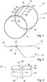
- the Fig. 1 shows a section of a support structure 10 of an aircraft 12, which has a stiffened by ribs 14 and stringer 16 outer skin 18.
- the stringers 16 include bonded stiffeners extending in a longitudinal direction of the aircraft 10.
- the Fig. 2 shows a part of the Fig. 1 with a structural component 20, which shows a part of the outer skin 18 and a part of a stringer 16.
- the stringer 16 is characterized by an outer shell 22, which forms part of the outer skin 18, and an inner shell 24 is formed, which is glued to the outer shell 22.
- the support structure has a shell structure with glued-in stiffeners.
- the outer shell 22 in this case represents a first component 22 of the structural component 20, which is connected to the inner shell 24 as a second component 24 via an adhesive connection 26 in the form of an adhesive joint.
- the first component 22 and the second component 24 are additionally connected via an indication pin 28, which is arranged in a region 30, so that it is exposed to a failure of the adhesive joint 26 a high load.
- one or more adhesive bonds 26 between the two components 22, 24 can be secured in each case over a plurality of indication pins 28.
- the Fig. 3 shows a part of the Fig. 2
- the two components 22, 24 may be constructed flat and / or plate-like.
- the adhesive bond 26 may comprise a layer of adhesive material between the two components 22, 24.
- the indication pin 28 is received in an opening 32 in the structural component 20 and fixed to the structural component 20.
- the indication pin 28 has a foot 34, which is fixed by means of a thickening 36 on the second thickening, so that the indication pin 28 is held on the second component 24 in the opening 32.
- the indication pin 28 has a head 38, which is thickened relative to the foot 34, so that the indication pin 28 is also held on the first component 22 in the opening 32.
- the two components 22, 24 are loaded by forces and loads exerted on the structural component 20, a relative movement beyond a predetermined limit may result.
- the two components 22, 24 can lift off one another and / or move along the adhesive connection 26.
- the predetermined limit value can be set, for example, via the elastic behavior of the indication pin 28 or via a clearance between the indication pin 28 and the first component 22 and / or the second component 24.
- the opening 32 has a diameter which is slightly larger than the diameter of the foot 34 of the indication pin 28.
- the indication pin 28 has a predetermined breaking point 40, which represents a tapered portion of the indication pin 28.
- the size of the predetermined breaking point 40 is adjusted so that at a certain load on the Indikationsbolzen28 the predetermined breaking point 40 is at least permanently deformed or torn off.
- the Fig. 4 shows that the head 38 of the indication pin 28 may be displaced or bent by a deformation of the indication pin 28 relative to the foot 34.
- the head 38 may be received in a recess 42 such that the surface of the head 38 is flush with the surface the first component 22 is aligned when the indication pin 28 is not deformed. After being deformed, the head 38 can protrude beyond the depression, so that a deformation of the indication pin 28 is also easily visible from the outside.
- the head 38 can also be completely separated from the foot 34 during the deformation of the indication pin 28, so that the recess 42 is exposed.
- a crack 44 for example by the predetermined breaking area 40, can be detected by means of a measuring device or sensor 46, which determines, for example, eddy currents in the indication pin 28 or its electrical resistance.
- the indication pin 28 may have a cavity 50 in the interior of which a substance 52 is enclosed when the indication pin 28 is not deformed.
- the indication pin 28 deforms, for example by the head 38 being partially sheared off, a connection is made from the cavity 50 to the outside and the substance 52, for example a signal color, can emerge from the indication pin 28.
- the opening 32 can completely penetrate the two components 22, 24 or else only partially penetrate the second component 24.
- the indication pin 28 may be screwed or glued into the second component 24.
- the Fig. 9 shows with reference to Fig. 8 a non-inventive method for detecting a damage of the structural component 20, in which it is determined whether the two components 22, 24 have loaded the indication pin 28 so strong that it has deformed.
- step 100 the two components 22, 24 are bonded, so that the adhesive bond 26 is formed.
- an opening 32 is created by the two components 22, 24.
- the opening may already be provided during the production of the components 22, 24 or subsequently drilled into the two components 22, 24.
- the creation of the opening 32 may be performed simultaneously for bonding in step 100 before or after.
- an indication pin 28 is inserted into the opening 32.
- the indication pin 28 does not have to be rigidly connected to both components 22, 24, but can only be fixed in the opening 32 in such a way that it is loaded when the two components 22, 24 move relative to one another. Part of the fixation can be done, for example, with the conical head 38.
- the foot 34 of the indication pin 28 can for example be screwed into one of the components 22, 24 and / or glued.
- the indication pin 28 can also be held in the opening 32 by means of a riveted connection.
- the structural member 20 may be used for its intended purpose. If the adhesive bond 26 is damaged (for example, by overstress or fatigue), the two components 22, 24 may move the two components 22, 24 relative to each other (beyond a predetermined limit).
- the indication pin 28 is designed or designed to begin to deform when this limit is exceeded.
- the head 38 of the indication pin 28 can be bent or sheared off and / or the cavity 50 can be opened in the interior of the indication pin 28.
- step 106 the indication pin 28 is tested for integrity. This can be done by visual inspection, by means of a measuring device and / or a sensor 46.
- an eddy current measurement can be performed on the indication pin 28 or an electrical resistance of the indication pin 28 can be determined. If the eddy current or the resistance drops below a predetermined value, this indicates damage to the adhesive bond 26.
- a substance 52 emerging from the indication pin 28 can be detected (for example, while the substance is emerging). This can be done simultaneously during the intended use of the composite component 20.
- a measuring device or sensor 46 can also be a noise that the indication pin 28 gives off when deforming or breaking, to be recorded. The sensor values can be recorded and evaluated later. An abutment of the measuring instrument or sensor 46 or certain sensor values then indicate damage to the adhesive connection 26.
- Fig. 10 shows a not belonging to the invention example of an indication pin 28, which is designed to migrate in a lifting of the compound 26 in a predetermined direction.
- the indication pin 28 may, for example, have barbs 48 or a corrugation (asymmetrical with respect to the direction). If the two components 22m 24 stand out several times, for example, the indication pin 28 moves in the direction described by the arrow. It can then be checked by visual inspection whether the indication pin 28 projects out of the opening 32, which indicates that the adhesive connection 26 is defective.
Landscapes
- Engineering & Computer Science (AREA)
- General Engineering & Computer Science (AREA)
- Mechanical Engineering (AREA)
- Aviation & Aerospace Engineering (AREA)
- Testing Of Devices, Machine Parts, Or Other Structures Thereof (AREA)
- Force Measurement Appropriate To Specific Purposes (AREA)
- Standing Axle, Rod, Or Tube Structures Coupled By Welding, Adhesion, Or Deposition (AREA)
- Connection Of Plates (AREA)
- Insertion Pins And Rivets (AREA)
Description
- Die Erfindung betrifft ein Strukturbauteil und ein Luftfahrzeug mit einem Strukturbauteil.
- Um eine Verbindung zwischen zwei Bauteilen bzw. Komponenten, beispielsweise eines Fahrzeugs, herzustellen, können Klebeverbindungen verwendet werden. Dabei unterscheidet man zwischen primär verklebten Verbindungen, bei denen der Klebevorgang während der Zeit durchgeführt wird, in der auch die beiden Bauteile geformt werden (beispielsweise in einer Presse), und sekundär verklebten Verbindungen, bei denen die Komponenten nachträglich miteinander verklebt werden.
- Bei einer Klebeverbindung eines tragenden Strukturbauteils kann es wichtig sein, betriebsbedingte Schäden zu überprüfen. Die meisten Klebeverbindungen sind nach der Fügung und dem Zusammenbau zur übergeordneten Struktur nicht mehr von allen Seiten zugänglich und können daher nicht mehr gut durch Sichtinspektion untersucht werden.
- In der Luftfahrt sind sekundär verklebte Verbindungen im Moment nicht zugelassen, da es in der Regel nicht möglich ist, auf einfache Art und Weise zu überprüfen, ob eine sekundär verklebte Verbindung beschädigt ist oder nicht.
- Bekannte Verfahren zum nicht-destruktiven Testen von Klebeverbindungen umfassen beispielsweise Ultraschall und Thermographie. Bei großen Wandstärken oder Dickenänderungen der Klebefuge sind diese Verfahren jedoch nur eingeschränkt anwendbar oder nur schwer einsetzbar.
- Auch bei einer fehlerhaften Verklebung, bei der nur unter Last ein Spalt zwischen den nicht mehr ordnungsgemäß verklebten Komponenten erzeugt wird (so genannte "kissing bonds"), kann mit oben genannten Verfahren häufig kein Fehler entdeckt werden.
- Aus diesen Gründen werden bei Klebeverbindungen häufig zusätzliche Klemmbolzen (siehe z.B.
WO 2006/102566 A ) verwendet, die dazu ausgeführt sind, die Last der Verbindung zu tragen, wenn die Klebeverbindung beschädigt ist. Solche Klemmbolzen können dann eine weitere Ausbreitung eines Schadens verzögern, können aber auch ein Erkennen des Schadens verhindern. - Es ist Aufgabe der Erfindung, ein einfach aufgebautes Strukturbauteil bereitzustellen, das leicht auf Schäden untersucht werden kann.
- Diese Aufgabe wird durch den Gegenstand der unabhängigen Ansprüche gelöst. Weitere Ausführungsformen der Erfindung ergeben sich aus den abhängigen Ansprüchen und aus der folgenden Beschreibung. Die Erfindung wird durch den Gegenstand des unabhängigen Anspruchs definiert.
- Ein erster Aspekt der Erfindung betrifft ein Strukturbauteil, beispielsweise ein Strukturbauteil eines Luftfahrzeugs, Bodenfahrzeugs oder Wasserfahrzeugs. Das Strukturbauteil kann aber auch Bestandteil anderer Vorrichtungen, wie etwa einer Windkraftanlage, sein. Ein Strukturbauteil kann dazu ausgeführt sein, einer auf das Fahrzeug bzw. die Vorrichtung wirkenden Last ausgesetzt zu sein. Beispielsweise kann die Strukturkomponente ein Bestandteil der Tragestruktur des Fahrzeugs sein.
- Das Strukturbauteil umfasst eine erste Komponente und eine zweite Komponente, die beispielsweise flächige und/oder plattenartige Komponenten sein können, die miteinander verklebt sind. Beide Komponenten bzw. Bauteile können aus Metall oder Kunststoff bestehen bzw. Metall und/oder Kunststoff umfassen. Ein derartiger Kunststoff kann beispielsweise ein kohlenstofffaserverstärkter Kunststoff sein.
- Die beiden Komponenten sind mittels einer Klebeverbindung miteinander verbunden, die beispielsweise zwischen den beiden Komponenten angebracht ist. Bei der Klebeverbindung kann es sich um eine sekundäre Klebeverbindung handeln. Mit anderen Worten können die beiden Komponenten getrennt voneinander geformt oder hergestellt worden sein und anschließend miteinander verklebt worden sein.
- Bei der Klebeverbindung bzw. Verklebung, die eine Schicht aus verfestigtem Kleber umfassen kann, kann es sich um eine strukturelle Verklebung von Faserverbundwerkstoffbauteilen oder um eine Reparaturklebung in Faserverbundwerkstoffen handeln.
- Gemäß einer Ausführungsform der Erfindung umfasst das Strukturbauteil einen Indikationsbolzen, der an der ersten Komponente und der zweiten Komponente fixiert ist. Mit anderen Worten kann der Indikationsbolzen beispielsweise wie ein Niet mit dem Strukturbauteil verbunden sein, muss aber nicht an den einzelnen Komponenten befestigt sein. Es ist jedoch möglich, dass der Indikationsbolzen zumindest abschnittsweise mit der ersten und/oder zweiten Komponente verbunden, beispielsweise verklebt, ist.
- Der Indikationsbolzen ist dazu ausgeführt, anzuzeigen, wenn die erste Komponente und die zweite Komponente sich relativ zueinander bewegt haben. Ein Indikationsbolzen kann ein Stift, Bolzen oder länglicher Körper (aus Metall, Kunststoff und/oder Glas) sein, der an beiden Komponenten fixierbar ist und mit dem eine Relativbewegung der beiden Komponenten nachweisbar bzw. detektierbar ist.
- Ist die Verklebung zwischen den beiden Komponenten im Bereich des Indikationsbolzens beschädigt und ist die Strukturkomponente einer Last ausgesetzt, können die beiden Komponenten sich relativ zueinander bewegen (beispielsweise sich zeitweise voneinander entfernen), da die Klebeverbindung sie zumindest in diesem Bereich nicht mehr vollständig aneinander bindet.
- Ein Versagen der Klebeverbindung durch Adhäsionsbruch (bei dem die Klebeschicht versagt) oder Kohäsionsbruch (bei dem das verklebte Material versagt) führt bei einer Belastung des Strukturbauteils zu einer (erhöhten) Relativbewegung der beiden Komponenten. Diese Relativbewegung führt dazu, dass der Indikationsbolzen sich an der Sollbruchstelle verformt, abbricht, zerbricht, und/oder aufplatzt, so dass am Indikationsbolzen festgestellt werden kann, dass eine Relativbewegung stattgefunden hat. Diese Relativbewegung kann beispielsweise eine Scherbewegung der beiden Komponenten und/oder ein Abheben der beiden Komponenten voneinander umfassen.
- Mit anderen Worten ist der Indikationsbolzen ein Bolzen zur Indikation einer Beschädigung einer geklebten Verbindung.
- Der Indikationsbolzen kann als nicht-tragender Indikationsbolzen ausgeführt sein. D.h. der Indikationsbolzen kann nur wenig oder einen geringen Beitrag zu der Festigkeit der Verbindung der beiden Komponenten leisten. Ein derartiger Indikationsbolzen kann insbesondere besonders leicht ausgeführt sein, so dass bei gleicher Belastbarkeit Gewicht für das Strukturbauteil eingespart werden kann.
- Mit dem Indikationsbolzen kann eine Verklebung einer Struktur überwacht werden.
- Gemäß einer Ausführungsform der Erfindung ist der Indikationsbolzen dazu ausgeführt, sich plastisch zu verformen, wenn die erste Komponente und die zweite Komponente sich relativ zueinander bewegt haben. Beispielsweise kann er sich dauerhaft verbiegen und/oder einen Riss ausbilden. Mit diesen Veränderungen kann später detektiert werden (in einem einfachen Fall durch Sichtkontrolle), ob eine Relativbewegung stattgefunden hat.
- Gemäß einer Ausführungsform der Erfindung ist der Indikationsbolzen derart der an der ersten Komponente und der zweiten Komponente fixiert, dass er anzeigt, wenn die Relativbewegung der ersten Komponente und der zweiten Komponente größer als ein vorbestimmter Grenzwert ist. Beispielsweise ist der Indikationsbolzen mit etwas Spiel an den beiden Komponenten befestigt, so dass sich erst dann eine Verformung des Indikationsbolzens ergibt, wenn sich die beiden Komponenten so stark bewegt haben, dass das Spiel ausgeglichen wurde.
- Einer oder mehrere Indikationsbolzen können an kritischen Stellen des Strukturbauteils angebracht werden, bei denen die Relativbewegung bei Versagen der Klebeverbindung besonders hoch ist. Die Versagenslast eines Indikationsbolzens kann auch an die Steifigkeit des umgebenden Strukturbauteils angepasst sein.
- Gemäß einer Ausführungsform der Erfindung ist der Indikationsbolzen in einer Öffnung im Strukturbauteil aufgenommen, die zumindest in der ersten Komponente und/oder der zweiten Komponente einen Durchmesser aufweist, der größer ist als ein Durchmesser des Indikationsbolzens. Durch einen Abstand zwischen dem Indikationsbolzen und der Öffnung kann der vorbestimmte Grenzwert definiert werden, um den sich die beiden Komponenten relativ zueinander bewegen können, ohne dass der Indikationsbolzen eine Relativbewegung anzeigt.
- Erfindungsgemäß weist der Indikationsbolzen eine Sollbruchstelle auf, die sich bei einer vorbestimmten Belastung des Indikationsbolzens verformt und/oder bei einer vorbestimmten Belastung des Indikationsbolzens zerbricht. Beispielsweise kann die Sollbruchstelle ein verjüngter Bereich des Indikationsbolzens sein. Wenn der Indikationsbolzen einen Kopf und einen Fuß aufweist, kann die Sollbruchstelle zwischen Kopf und Fuß angeordnet sein.
- Gemäß einer Ausführungsform der Erfindung weist der Indikationsbolzen einen Kopf auf, der an der ersten Komponente fixiert ist und weist der Indikationsbolzen einen länglichen Fuß auf, der an der zweiten Komponente fixiert ist. Beispielsweise kann der Kopf gegenüber dem Fuß verdickt sein, so dass er nicht wie der Fuß durch eine Öffnung in der ersten und der zweiten Komponente passt. Der Fuß kann beispielsweise auch eine Verdickung aufweisen, die nicht durch diese Öffnung passt oder kann mit der zweiten Komponente verklebt und/oder verschraubt sein.
- Gemäß einer Ausführungsform der Erfindung verbiegt sich der Kopf bei einer vorbestimmten Belastung des Indikationsbolzens gegenüber dem Fuß. Auf diese Weise kann durch einfache Sichtinspektion festgestellt werden, ob eine Beschädigung der Klebeverbindung möglich ist.
- Gemäß einer Ausführungsform der Erfindung löst sich der Kopf (oder ein Bestandteil des Kopfes) bei einer vorbestimmten Belastung des Indikationsbolzens von dem Fuß. Ist der Kopf farbig markiert, kann so auf einfache Weise das Fehlen des Kopfes festgestellt werden.
- Gemäß einer Ausführungsform der Erfindung weist der Indikationsbolzen einen Kopf auf, der in der ersten Komponente versenkt ist, so dass die erste Komponente zusammen mit dem Kopf eine ebene Oberfläche aufweist. Wenn der Kopf verbogen ist bzw. nicht mehr vorhanden ist, kann beispielsweise durch Befühlen der Oberfläche festgestellt werden, ob sich der Indikationsbolzen verformt hat.
- Gemäß einer Ausführungsform der Erfindung umfasst der Indikationsbolzen eine geschlossene Kavität, die bei Verformung des Bolzens geöffnet wird. Der Bolzen kann die Form eines (an den Enden geschlossenen) Rohrs aufweisen. Wird der Bolzen geöffnet, kann ein Material oder eine Substanz (flüssig, gasförmig oder fest) aus dem Bolzen austreten, über die die Verformung des Indikationsbolzen festgestellt werden kann. Beispielsweise enthält die Kavität eine detektierbare Substanz, beispielsweise eine Signalfarbe und/oder einen Geruchsstoff.
- Gemäß einer Ausführungsform der Erfindung ist der Indikationsbolzen mit dem Strukturbauteil vernietet. Der Indikationsbolzen kann dadurch an dem Strukturbauteil fixiert werden, dass er durch eine Öffnung im Strukturbauteil gesteckt wird und sein anderes Ende derart verdickt wird, dass der Indikationsbolzen nicht mehr aus der Öffnung fallen kann.
- Gemäß einer Ausführungsform der Erfindung ist ein Fuß des Indikationsbolzens in wenigstens die zweite Komponente geschraubt. Der Fuß kann aber auch zusätzlich mit der ersten Komponente verschraubt sein. Auf diese Weise muss die Öffnung nicht die zweite Komponente vollständig durchdringen, sondern kann nur teilweise durch die zweite Komponente reichen. Auf diese Weise kann die Belastbarkeit der Strukturkomponente erhöht werden.
- Ein weiterer Aspekt der Erfindung betrifft ein Luftfahrzeug mit einem Strukturbauteil, so wie es obenstehend und untenstehend beschrieben ist. Im Allgemeinen kann der Indikationsbolzen beispielsweise bei einer Klebeverbindung von Bauteilen eines Fahrzeugs, wie etwa einem Luftfahrzeug, einem Flugzeug, einem Bodenfahrzeug, einem Pkw, Lkw, Bus, einem Wasserfahrzeug, einem Schiff, einem Segelboot verwendet werden. Auch kann der Indikationsbolzen beispielsweise bei einer Klebeverbindung von Bauteilen einer Windkraftanlage, beispielsweise deren Flügeln, verwendet werden.
- Zum besseren Verständnis der Erfindung ist ein nicht erfindungsgemäßes Verfahren zum Detektieren einer Beschädigung eines Strukturbauteils beschrieben, das die folgenden Schritte umfasst: Fixieren eines Indikationsbolzens an einer ersten Komponente und einer zweiten Komponente des Strukturbauteils, die miteinander verklebt sind; und Detektieren einer Verformung des Indikationsbolzens, die dadurch entsteht, dass sich die erste Komponente und die zweite Komponente aufgrund einer Beschädigung der Klebeverbindung voneinander relativ zueinander bewegen.
- Die Detektion ist beispielsweise mittels einer optischen Detektion möglich, die direkt von einem Wartungstechniker ohne weitere Hilfsmittel durchgeführt werden kann. Ein vorstehender, schiefstehender und/oder abgeplatzter Kopf des Indikationsbolzens kann durch einfache Sichtprüfung erkannt werden.
- Auch ist eine akustische Detektion möglich, beispielsweise über Geräusche, die von einem versagenden Indikationsbolzen abgegeben werden. Beispielsweise kann in einer Kavität im Inneren des Bolzens ein Überdruck vorhanden sein, der bei einer Beschädigung des Bolzens entweicht und dabei ein charakteristisches Geräusch abgibt. Dieses Geräusch kann beispielsweise von einem Sensor aufgezeichnet und später ausgewertet werden.
- Gemäß einem nicht erfindungsgemäßen Beispiel umfasst das Verfahren weiter den Schritt von Detektieren der Verformung mittels (dem Detektieren) einer Substanz, die aus dem Indikationsbolzens austritt, wenn dieser verformt wird.
- Hierbei ist beispielsweise eine chemische Detektion des austretenden Stoffes möglich, der beispielsweise von einem Sensor erfasst werden und ausgewertet werden kann. Auch das Austreten eines Geruchsstoffes kann beispielsweise von einem Wartungstechniker oder einer Person in der Nähe des Strukturbauteils ohne Hilfsmittel wahrgenommen werden.
- Weiter ist es möglich, dass ein Farbstoff aus dem Bolzen nach der Verformung bzw. Beschädigung austritt. Der Farbstoff bzw. eine Farbe, wie etwa eine Signalfarbe, kann in der Nähe des Bolzens, beispielsweise auf der Oberfläche der ersten Komponente, antrocknen und dort einen dauerhaften Hinweis auf die Verformung des Bolzens hinterlassen.
- Gemäß einem weiteren nicht erfindungsgemäßen Beispiel umfasst das Verfahren weiter den Schritt von Detektieren der Verformung mittels einer Veränderung einer elektrischen Eigenschaft des Indikationsbolzens. Auf diese Weise ist es möglich, eine Verformung und/oder Beschädigung des Indikationsbolzens zu detektieren, die mit bloßem Auge nicht möglich ist.
- Beispielsweise kann der Indikationsbolzen mittels Wirbelströmen untersucht werden. Wirbelstrommessgeräte, mit denen auch ein bildgebendes Verfahren eingesetzt werden kann, sind weit verbreitet und in der Regel einfach bedienbar.
- Auch ist es möglich, eine Widerstandsmessung am Indikationsbolzen durchzuführen. Ist der Indikationsbolzen beispielsweise in einer Weise gebrochen, dass der Bruch von außen nicht sichtbar ist, kann jedoch der elektrische Widerstand des Bolzens signifikant erhöht sein.
- Es ist zu verstehen, dass die Detektionsmöglichkeiten einzeln oder in Kombination angewendet werden können.
- Im Folgenden werden Ausführungsbeispiele der Erfindung mit Bezug auf die beiliegenden Figuren detailliert beschrieben.
-
-
Fig. 1 zeigt eine schematische dreidimensionale Ansicht einer Tragestruktur eines Flugzeugs gemäß einer Ausführungsform der Erfindung. -
Fig. 2 zeigt einen schematischen Querschnitt durch ein Strukturbauteil gemäß einer Ausführungsform der Erfindung. -
Fig. 3 zeigt einen schematischen Querschnitt durch ein Strukturbauteil mit einem unbeschädigten Indikationsbolzen gemäß einer Ausführungsform der Erfindung. -
Fig. 4 zeigt einen schematischen Querschnitt durch ein Strukturbauteil mit einem beschädigten Indikationsbolzen gemäß einer Ausführungsform der Erfindung. -
Fig. 5 zeigt einen schematischen Querschnitt durch ein Strukturbauteil mit einem beschädigten Indikationsbolzen gemäß einer Ausführungsform der Erfindung. -
Fig. 6 zeigt einen schematischen Querschnitt durch ein Strukturbauteil mit einem beschädigten Indikationsbolzen gemäß einer Ausführungsform der Erfindung. -
Fig. 7 zeigt einen schematischen Querschnitt durch ein Strukturbauteil mit einem unbeschädigten Indikationsbolzen gemäß einer Ausführungsform der Erfindung. -
Fig. 8 zeigt einen schematischen Querschnitt durch ein Strukturbauteil mit einem beschädigten Indikationsbolzen gemäß einer Ausführungsform der Erfindung. -
Fig. 9 zeigt ein Flussdiagramm für ein nicht erfindungsgemäßes Verfahren zur Detektion einer defekten Klebeverbindung gemäß einem nicht erfindungsgemäßen Beispiel . -
Fig. 10 zeigt einen schematischen Querschnitt durch ein Strukturbauteil mit einem Indikationsbolzen gemäß einem nicht erfindungsgemäßen Beispiel. - Grundsätzlich sind identische oder ähnliche Teile mit den gleichen Bezugszeichen versehen.
- Die
Fig. 1 zeigt einen Ausschnitt aus einer Tragestruktur 10 eines Flugzeugs 12, die eine durch Spanten 14 und Stringer 16 versteifte Außenhaut 18 aufweist. Die Stringer 16 umfassen verklebte Versteifungen, die in einer Längsrichtung des Flugzeugs 10 verlaufen. - Die
Fig. 2 zeigt einen Ausschnitt aus derFig. 1 mit einem Strukturbauteil 20, das einen Teil der Außenhaut 18 und einen Teil eines Stringers 16 zeigt. Der Stringer 16 ist dabei durch eine Außenschale 22, die einen Teil der Außenhaut 18 bildet, und eine Innenschale 24 gebildet, die mit der Außenschale 22 verklebt ist. Insgesamt weist die Tragestruktur eine Schalenstruktur mit eingeklebten Versteifungen auf. - Die Außenschale 22 stellt dabei eine erste Komponente 22 des Strukturbauteils 20 dar, die mit der Innenschale 24 als zweite Komponente 24 über eine Klebeverbindung 26 in der Form einer Klebefuge verbunden ist.
- Die erste Komponente 22 und die zweite Komponente 24 sind zusätzlich über einen Indikationsbolzen 28 verbunden, der in einem Bereich 30 angeordnet ist, so dass er bei einem Versagen der Klebeverbindung 26 einer hohen Belastung ausgesetzt ist.
- Wie aus der
Fig. 1 hervorgeht, können eine oder mehrere Klebeverbindungen 26 zwischen den beiden Komponenten 22, 24 jeweils über mehrere Indikationsbolzen 28 gesichert sein. - Die
Fig. 3 zeigt einen Ausschnitt aus derFig. 2 . In einer Umgebung des Indikationsbolzens 28 können die beiden Komponenten 22, 24 flächig und/oder plattenartig aufgebaut sein. Die Klebeverbindung 26 kann eine Schicht Klebematerial zwischen den beiden Komponenten 22, 24 umfassen. - Der Indikationsbolzen 28 ist in einer Öffnung 32 in dem Strukturbauteil 20 aufgenommen und an dem Strukturbauteil 20 fixiert. Dazu weist der Indikationsbolzen 28 einen Fuß 34 auf, der mittels einer Verdickung 36 an der zweiten Verdickung fixiert ist, so dass der Indikationsbolzen 28 an der zweiten Komponente 24 in der Öffnung 32 gehalten wird. Weiter weist der Indikationsbolzen 28 einen Kopf 38 auf, der gegenüber dem Fuß 34 verdickt ist, so dass der Indikationsbolzen 28 auch an der ersten Komponente 22 in der Öffnung 32 gehalten wird.
- Wenn die Klebeverbindung 26 beschädigt ist und die beiden Komponenten 22, 24 durch Kräfte und Lasten, die auf die Strukturkomponente 20 ausgeübt werden, belastet werden, kann eine Relativbewegung über einen vorbestimmten Grenzwert hinaus entstehen. Beispielsweise können die beiden Komponenten 22, 24 voneinander abheben und/oder sich entlang der Klebeverbindung 26 verschieben.
- Der vorbestimmte Grenzwert kann beispielsweise über das elastische Verhalten des Indikationsbolzens 28 oder über ein Spiel zwischen dem Indikationsbolzen 28 und der ersten Komponente 22 und/oder der zweiten Komponente 24 eingestellt werden. Beispielsweise weist die Öffnung 32 einen Durchmesser auf, der etwas größer als der Durchmesser des Fußes 34 des Indikationsbolzens 28 ist.
- Bei einer genügen großen Relativbewegung der beiden Komponenten 22, 24 wird der Indikationsbolzen dann derart belastet, dass beispielsweise sein Kopf 38 abschert oder zumindest abgeknickt wird.
- Zwischen dem Kopf 38 und dem Fuß 34 weist der Indikationsbolzen 28 eine Sollbruchstelle 40 auf, die einen verjüngten Abschnitt des Indikationsbolzen 28 darstellt. Die Größe der Sollbruchstelle 40 ist so abgestimmt, dass bei einer bestimmten Last auf den Indikationsbolzen28 die Sollbruchstelle 40 sich zumindest dauerhaft verformt oder abreißt.
- Die
Fig. 4 zeigt, dass der Kopf 38 des Indikationsbolzens 28 durch eine Verformung des Indikationsbolzen 28 gegenüber dem Fuß 34 verschoben oder verbogen sein kann. - Wie aus der
Fig. 3 hervorgeht, kann der Kopf 38 beispielsweise in einer Vertiefung 42 aufgenommen sein, so dass die Oberfläche des Kopfes 38 mit der Oberfläche der ersten Komponente 22 fluchtet, wenn der Indikationsbolzen 28 nicht verformt ist. Nach dem Verformen kann der Kopf 38 über die Vertiefung hinausstehen, so dass eine Verformung des Indikationsbolzen 28 auch von außen leicht sichtbar ist. - In der
Fig. 5 ist gezeigt, dass der Kopf 38 beim Verformen des Indikationsbolzens 28 auch vollständig vom Fuß 34 getrennt werden kann, so dass die Vertiefung 42 freigelegt wird. - Auch wenn, wie es in der
Fig. 6 gezeigt ist, der Kopf 38 des Indikationsbolzens 28 keine sichtbare Verformung zeigt, kann ein Riss 44, beispielsweise durch den Sollbruchbereich 40, mittels eines Messgeräts oder Sensors 46 detektiert werden, das beispielsweise Wirbelströme im Indikationsbolzen 28 oder dessen elektrischen Widerstand bestimmt. - In der
Fig. 7 ist dargestellt, dass der Indikationsbolzen 28 eine Kavität 50 aufweisen kann, in deren Innerem eine Substanz 52 eingeschlossen ist, wenn der Indikationsbolzen 28 nicht verformt ist. - Verformt sich der Indikationsbolzen 28, beispielsweise indem der Kopf 38 teilweise abgeschert wird, wird eine Verbindung von der Kavität 50 nach außen hergestellt und die Substanz 52, beispielsweise eine Signalfarbe, kann aus dem Indikationsbolzen 28 austreten.
- In der
Fig. 7 ist zusätzlich gezeigt, dass die Öffnung 32 die beiden Komponenten 22, 24 vollständig durchdringen kann oder aber auch die zweite Komponente 24 nur teilweise durchdringt. In beiden Fällen kann der Indikationsbolzen 28 in die zweite Komponente 24 geschraubt oder geklebt sein. - Die
Fig. 9 zeigt mit Bezug aufFig. 8 ein nicht erfindungsgemäßes Verfahren zur Detektion einer Beschädigung des Strukturbauteils 20, bei dem ermittelt wird, ob die beiden Komponenten 22, 24 den Indikationsbolzen 28 derart stark belastet haben, dass er sich verformt hat. - Im Schritt 100 werden die beiden Komponenten 22, 24 verklebt, so dass die Klebeverbindung 26 entsteht.
- Im Schritt 102 wird eine Öffnung 32 durch die beiden Komponenten 22, 24 erzeugt. Beispielsweise kann die Öffnung schon beim Herstellen der Komponenten 22, 24 vorgesehen sein oder nachträglich in die beiden Komponenten 22, 24 gebohrt werden. Das Erzeugen der Öffnung 32 kann gleichzeitig zum Verkleben im Schritt 100 davor oder danach durchgeführt werden.
- In Schritt 104 wird ein Indikationsbolzen 28 in die Öffnung 32 eingesetzt. Der Indikationsbolzen 28 muss nicht mit beiden Komponenten 22, 24 starr verbunden sein, sondern kann lediglich so in der Öffnung 32 fixiert sein, dass er belastet wird, wenn sich die beiden Komponenten 22, 24 relativ zueinander bewegen. Ein Teil der Fixierung kann beispielsweise mit dem konischen Kopf 38 geschehen.
- Der Fuß 34 des Indikationsbolzens 28 kann beispielsweise in eine der Komponenten 22, 24 eingeschraubt und/oder eingeklebt werden. Auch kann der Indikationsbolzen 28 mittels einer Nietverbindung in der Öffnung 32 gehalten werden.
- Danach kann das Strukturbauteil 20 zu seiner vorgesehenen Bestimmung verwendet werden. Wird die Klebeverbindung 26 (beispielsweise durch eine Überbeanspruchung oder durch Materialermüdung) beschädigt, können sich die beiden Komponenten 22, 24 sich die beiden Komponenten 22, 24 (über einen vorbestimmten Grenzwert hinaus) relativ zueinander bewegen. Der Indikationsbolzen 28 ist so ausgelegt bzw. ausgeführt, dass er sich zu verformen beginnt, wenn dieser Grenzwert überschritten wird.
- Durch das Verformen des Indikationsbolzens 28 kann beispielsweise der Kopf 38 des Indikationsbolzens 28 verbogen oder abgeschert werden und/oder die Kavität 50 im Inneren des Indikationsbolzens 28 geöffnet werden.
- Im Schritt 106 wird der Indikationsbolzen 28 auf seine Unversehrtheit getestet. Dies kann durch Sichtkontrolle, mittels eines Messgeräts und/oder eines Sensors 46 erfolgen.
- Mit einer Sichtkontrolle kann ermittelt werden, ob der Kopf 38 des Indikationsbolzens 28 verbogen oder noch vorhanden ist oder ob eine Signalfarbe 52 ausgetreten ist. Ein verbogener oder verschwundener Kopf 38 bzw. das Vorhandensein einer Signalfarbe 52 deutet darauf hin, dass die Klebeverbindung 26 beschädigt wurde.
- Mit einem Messgerät oder Sensor 46 kann eine Wirbelstrommessung an dem Indikationsbolzen 28 durchgeführt werden oder ein elektrischer Widerstand des Indikationsbolzens 28 ermittelt werden. Sinkt der Wirbelstrom oder der Widerstand unter einen vorbestimmten Wert, deutet dies auf eine Beschädigung der Klebeverbindung 26 hin.
- Mit einem Messgerät oder Sensor 46 kann ein aus dem Indikationsbolzen 28 austretender Stoff 52 detektiert werden (beispielsweise während der Stoff austritt). Dies kann gleichzeitig während der bestimmungsgemäßen Verwendung des Verbundbauteils 20 erfolgen. Mit einem Messgerät oder Sensor 46 kann auch ein Geräusch, das der Indikationsbolzen 28 beim Verformen oder Zerbrechen abgibt, aufgezeichnet werden. Die Sensorwerte können aufgezeichnet und später ausgewertet werden. Ein Anschlagen des Messgeräts oder Sensors 46 oder bestimmte Sensorwerte deuten dann auf eine Beschädigung der Klebeverbindung 26 hin.
Fig. 10 zeigt ein nicht zur Erfindung gehörendes Beispiel eines Indikationsbolzens 28, der dazu ausgeführt ist, bei einem Abheben der Verbindung 26 in eine vorgegebene Richtung zu wandern. Der Indikationsbolzen 28 kann beispielsweise Widerhaken 48 oder eine (bezüglich der Richtung asymmetrische) Riffelung aufweisen. Wenn sich die beiden Komponenten 22m 24 beispielsweise mehrmals voneinander abheben, wandert der Indikationsbolzen 28 in die mit dem Pfeil beschriebene Richtung. Anschließend kann durch Sichtkontrolle überprüft werden, ob der Indikationsbolzen 28 aus der Öffnung 32 heraus ragt, was darauf hindeutet dass die Klebeverbindung 26 defekt ist. - Ergänzend ist darauf hinzuweisen, dass "umfassend" keine anderen Elemente oder Schritte ausschließt und "eine" oder "ein" keine Vielzahl ausschließt. Bezugszeichen in den Ansprüchen sind nicht als Einschränkung anzusehen.
Claims (12)
- Strukturbauteil (20), umfassend:eine erste Komponente (22) und eine zweite Komponente (24);eine Klebeverbindung (26), mit der die erste Komponente (22) und die zweite Komponente (24) miteinander verbunden sind;einen Indikationsbolzen (28), der an der ersten Komponente (22) und der zweiten Komponente (24) fixiert ist;wobei der Indikationsbolzen (28) dazu ausgeführt ist, anzuzeigen, wenn die erste Komponente (22) und die zweite Komponente (24) sich relativ zueinander bewegt haben;
dadurch gekennzeichnet, dass der Indikationsbolzen (28) eine Sollbruchstelle (40) aufweist, die sich bei einer vorbestimmten Belastung des Indikationsbolzens (28) verformt oder bei einer vorbestimmten Belastung des Indikationsbolzens (28) zerbricht. - Strukturbauteil (20) nach Anspruch 1,
wobei der Indikationsbolzen (28) derart der an der ersten Komponente (22) und der zweiten Komponente (24) fixiert ist, dass er anzeigt, wenn die Relativbewegung der ersten Komponente (22) und der zweiten Komponente (24) größer als ein vorbestimmter Grenzwert ist. - Strukturbauteil (20) nach Anspruch 1 oder 2,
wobei der Indikationsbolzen (28) dazu ausgeführt ist, sich plastisch zu verformen, wenn die erste Komponente (22) und die zweite Komponente (24) sich relativ zueinander bewegt haben. - Strukturbauteil (20) nach einem der vorhergehenden Ansprüche,
wobei der Indikationsbolzen (28) in einer Öffnung (32) im Strukturbauteil (20) aufgenommen ist, die zumindest in der ersten Komponente (22) und/oder der zweiten Komponente (24) einen Durchmesser aufweist, der größer ist als ein Durchmesser des Indikationsbolzens (28). - Strukturbauteil (20) nach einem der vorhergehenden Ansprüche,
wobei der Indikationsbolzen (28) einen Kopf (28) aufweist, der an der ersten Komponente (22) fixiert ist und der Indikationsbolzen (28) einen länglichen Fuß (34) aufweist, der an der zweiten Komponente (34) fixiert ist;
wobei sich der Kopf (38) bei einer vorbestimmten Belastung des Indikationsbolzens (28) gegenüber dem Fuß (34) verbiegt, oder
wobei sich der Kopf (38) bei einer vorbestimmten Belastung des Indikationsbolzens (28) von dem Fuß (34) des Indikationsbolzens (28) löst. - Strukturbauteil (20) nach einem der vorhergehenden Ansprüche,
wobei der Indikationsbolzen (28) einen Kopf (38) aufweist, der in der ersten Komponente (22) versenkt ist, so dass die erste Komponente (22) zusammen mit dem Kopf (38) eine ebene Oberfläche aufweist. - Strukturbauteil (20) nach einem der vorhergehenden Ansprüche,
wobei der Indikationsbolzen (28) eine geschlossene Kavität (50) umfasst, die bei Verformung des Indikationsbolzens (28) geöffnet wird. - Strukturbauteil (20) nach Anspruch 7,
wobei die Kavität (50) eine detektierbare Substanz (52) enthält. - Strukturbauteil (20) nach Anspruch 7 oder 8,
wobei die Kavität (50) eine Signalfarbe (52) enthält. - Strukturbauteil (20) nach einem der vorhergehenden Ansprüche,
wobei der Indikationsbolzen (28) mit dem Strukturbauteil vernietet ist. - Strukturbauteil (20) nach einem der vorhergehenden Ansprüche,
wobei ein Fuß (34) des Indikationsbolzens (28) in wenigstens die zweite Komponente (24) geschraubt ist. - Luftfahrzeug (12) mit einem Strukturbauteil (20) nach einem der vorhergehenden Ansprüche.
Applications Claiming Priority (2)
| Application Number | Priority Date | Filing Date | Title |
|---|---|---|---|
| DE102012023717.0A DE102012023717A1 (de) | 2012-12-05 | 2012-12-05 | Indikationsbolzen zur Überwachung von Klebeverbindungen in Strukturbauteilen |
| PCT/DE2013/000714 WO2014086331A1 (de) | 2012-12-05 | 2013-12-02 | Indikationsbolzen zur überwachung von klebeverbindungen in strukturbauteilen |
Publications (2)
| Publication Number | Publication Date |
|---|---|
| EP2929194A1 EP2929194A1 (de) | 2015-10-14 |
| EP2929194B1 true EP2929194B1 (de) | 2018-06-06 |
Family
ID=50070249
Family Applications (1)
| Application Number | Title | Priority Date | Filing Date |
|---|---|---|---|
| EP13828767.7A Active EP2929194B1 (de) | 2012-12-05 | 2013-12-02 | Indikationsbolzen zur überwachung von klebeverbindungen in strukturbauteilen |
Country Status (10)
| Country | Link |
|---|---|
| US (1) | US10071817B2 (de) |
| EP (1) | EP2929194B1 (de) |
| JP (1) | JP6267720B2 (de) |
| KR (1) | KR20150123222A (de) |
| CN (1) | CN105164430B (de) |
| BR (1) | BR112015012776A2 (de) |
| CA (1) | CA2892765A1 (de) |
| DE (1) | DE102012023717A1 (de) |
| RU (1) | RU2015123292A (de) |
| WO (1) | WO2014086331A1 (de) |
Families Citing this family (3)
| Publication number | Priority date | Publication date | Assignee | Title |
|---|---|---|---|---|
| DE102014200143B4 (de) * | 2014-01-08 | 2020-10-29 | Bayerische Motoren Werke Aktiengesellschaft | Vorrichtung zur Bestimmung der Querverschiebung zwischen zwei Bauteilen an einem Fügepunkt |
| US11598356B2 (en) | 2019-05-24 | 2023-03-07 | Hamilton Sundstrand Corporation | Fused alignment pin |
| KR20250071021A (ko) * | 2023-11-14 | 2025-05-21 | 주식회사 화신볼트산업 | 볼트의 수명 예측 시스템 및 방법 |
Citations (1)
| Publication number | Priority date | Publication date | Assignee | Title |
|---|---|---|---|---|
| WO2006102566A2 (en) * | 2005-03-23 | 2006-09-28 | Bell Helicopter Textron, Inc. | Apparatus for joining members and assembly thereof |
Family Cites Families (31)
| Publication number | Priority date | Publication date | Assignee | Title |
|---|---|---|---|---|
| JPS5144834Y2 (de) | 1973-02-14 | 1976-10-30 | ||
| GB1471666A (en) | 1973-07-19 | 1977-04-27 | Ocean Investments Ltd | Method and fastener for use in joining together an assembly of metal sheets |
| US4220092A (en) * | 1978-08-22 | 1980-09-02 | The United States Of America As Represented By The Secretary Of The Army | Leaf-spring color-disseminating projectile for training cartridge |
| US5019196A (en) * | 1989-11-20 | 1991-05-28 | Cmi International, Inc. | Sand muller bowl liner |
| US5129452A (en) * | 1990-02-23 | 1992-07-14 | Oil Dynamics, Inc. | Flexible electrical submersible motor pump system for deviated wells |
| US5088867A (en) | 1990-11-26 | 1992-02-18 | Mun Kam C | Fasteners that bleed fluid upon failure |
| US5120168A (en) * | 1990-12-06 | 1992-06-09 | Padula William V | Auto-torque, tamper-proof screw/bolt |
| DE4221607C1 (de) * | 1992-07-01 | 1993-09-09 | Deutsche Aerospace Airbus Gmbh, 21129 Hamburg, De | |
| EP0623758A3 (de) * | 1993-05-07 | 1994-11-30 | ALUSUISSE-LONZA SERVICES Ltd. | Sicherungsvorrichtung |
| CN2209573Y (zh) * | 1994-07-20 | 1995-10-11 | 北京市三禾内燃机车高新技术开发公司 | 螺栓液压拉伸器 |
| JPH08121442A (ja) * | 1994-10-26 | 1996-05-14 | Mitsubishi Electric Corp | 接着接合体及びその接合方法並びにリベット |
| US5713705A (en) * | 1996-03-01 | 1998-02-03 | Gruenbichler; Carl | Fastener bolt with limited torque head |
| DE19610749A1 (de) * | 1996-03-19 | 1997-09-25 | Daimler Benz Ag | Klebeverbindung bei insbesondere Fahr- oder Flugzeugteilen |
| US20020014572A1 (en) | 2000-04-05 | 2002-02-07 | Albritton Charles Wade | Method and apparatus for joining material |
| JP4198470B2 (ja) * | 2001-05-15 | 2008-12-17 | 積水樹脂株式会社 | パイプ継手およびこのパイプ継手を用いた組立体 |
| JP3709169B2 (ja) * | 2002-03-04 | 2005-10-19 | 株式会社荏原製作所 | 導電性材料の損傷診断方法及び診断装置 |
| FR2869655B1 (fr) * | 2004-04-28 | 2008-12-19 | Airbus France Sas | Procede d'assemblage de pieces structurales et assemblage obtenu. |
| US7351022B2 (en) | 2004-09-30 | 2008-04-01 | Denslow Clark A | Unified multi-part head for a staked fastener |
| US7954179B2 (en) * | 2007-02-01 | 2011-06-07 | Johnson Charles W | Water closet bolt |
| DE102007033126B4 (de) * | 2007-07-16 | 2011-06-09 | Böllhoff Verbindungstechnik GmbH | Verfahren zum Herstellen einer Nagelverbindung sowie Nagel hierfür |
| GB0723506D0 (en) * | 2007-12-03 | 2008-01-09 | Airbus Uk Ltd | Apparatus for indicating loading in a structure having exceeded a predetermined threshold |
| US8932418B2 (en) * | 2007-12-21 | 2015-01-13 | Airbus Operations Gmbh | Hybrid joining method for lap joints |
| US20090191019A1 (en) * | 2008-01-29 | 2009-07-30 | Disney Enterprises, Inc. | Fastener safety retention |
| WO2009094775A1 (en) | 2008-01-29 | 2009-08-06 | Magna Seating Inc. | Conic flange pivot joint |
| GB0819159D0 (en) * | 2008-10-20 | 2008-11-26 | Airbus Uk Ltd | Joint between aircraft components |
| DE102009009112A1 (de) * | 2009-02-16 | 2010-11-04 | Benteler Automobiltechnik Gmbh | Kraftfahrzeug-Strukturbauteil sowie Verfahren und Vorrichtung zur Herstellung eines Kraftfahrzeug-Strukturbauteils |
| US9012006B2 (en) | 2009-09-25 | 2015-04-21 | Shiloh Industries, Inc. | Multi-layer assembly with retention feature |
| WO2011129435A1 (ja) | 2010-04-16 | 2011-10-20 | 株式会社古河テクノマテリアル | 陥入爪矯正具、陥入爪矯正具の製造方法、および陥入爪矯正具の耐久性と矯正力の向上方法 |
| DE102010035950A1 (de) | 2010-08-31 | 2012-03-01 | Audi Ag | Verfahren zur Herstellung einer Nagelverbindung zwischen wenigstens zwei Fügeteilen |
| CN201925305U (zh) * | 2011-03-02 | 2011-08-10 | 杜德机械科技(上海)有限公司 | 预紧应力指示螺栓 |
| DE102012109517A1 (de) * | 2012-10-08 | 2014-04-10 | Dr. Ing. H.C. F. Porsche Aktiengesellschaft | Kraftfahrzeugrohbau und Verfahren zum Herstellen desselben |
-
2012
- 2012-12-05 DE DE102012023717.0A patent/DE102012023717A1/de not_active Withdrawn
-
2013
- 2013-12-02 RU RU2015123292A patent/RU2015123292A/ru not_active Application Discontinuation
- 2013-12-02 CN CN201380063771.9A patent/CN105164430B/zh active Active
- 2013-12-02 KR KR1020157017445A patent/KR20150123222A/ko not_active Withdrawn
- 2013-12-02 JP JP2015545664A patent/JP6267720B2/ja active Active
- 2013-12-02 EP EP13828767.7A patent/EP2929194B1/de active Active
- 2013-12-02 WO PCT/DE2013/000714 patent/WO2014086331A1/de not_active Ceased
- 2013-12-02 CA CA2892765A patent/CA2892765A1/en not_active Abandoned
- 2013-12-02 US US14/649,830 patent/US10071817B2/en active Active
- 2013-12-02 BR BR112015012776A patent/BR112015012776A2/pt not_active IP Right Cessation
Patent Citations (1)
| Publication number | Priority date | Publication date | Assignee | Title |
|---|---|---|---|---|
| WO2006102566A2 (en) * | 2005-03-23 | 2006-09-28 | Bell Helicopter Textron, Inc. | Apparatus for joining members and assembly thereof |
Also Published As
| Publication number | Publication date |
|---|---|
| BR112015012776A2 (pt) | 2017-07-11 |
| CA2892765A1 (en) | 2014-06-12 |
| EP2929194A1 (de) | 2015-10-14 |
| KR20150123222A (ko) | 2015-11-03 |
| JP2016503508A (ja) | 2016-02-04 |
| CN105164430B (zh) | 2018-09-18 |
| CN105164430A (zh) | 2015-12-16 |
| US20150307205A1 (en) | 2015-10-29 |
| RU2015123292A (ru) | 2017-01-12 |
| DE102012023717A1 (de) | 2014-06-05 |
| JP6267720B2 (ja) | 2018-01-24 |
| WO2014086331A1 (de) | 2014-06-12 |
| US10071817B2 (en) | 2018-09-11 |
Similar Documents
| Publication | Publication Date | Title |
|---|---|---|
| EP2603430A1 (de) | Beplankungsplatte für ein strukturbauteil, strömungskörper mit einer solchen beplankungsplatte sowie vorrichtung zur überwachung eines materialschadens an einer beplankungsplatte | |
| DE102007003276B4 (de) | Luft- und Raumfahrzeug mit einem CFK-Bauteil und einem Metallbauteil, wobei das CFK-Bauteil und das Metallbauteil über wenigstens ein Verbindungselement mit einem Verbindungsabschnitt miteinander verbunden sind | |
| WO2012076168A2 (de) | Durchführung für blitzschutzkabel | |
| EP1678474A2 (de) | Vorrichtung zur feststellung von belastungen an faserverbund-bauteilen | |
| DE102017113430A1 (de) | Verfahren und Vorrichtung zum Überprüfen einer Fügeoberfläche | |
| WO2018206770A1 (de) | Verfahren zur vorhersage von versagenslasten von strukturen aus faserverbundwerkstoffen auf basis von schallemissionsdaten | |
| DE102009027807A1 (de) | Detektionsverfahren und Detektionsvorrichtung zum Detektieren von Kernschäden und Ablösungen in Sandwichstrukturen | |
| WO2014086331A1 (de) | Indikationsbolzen zur überwachung von klebeverbindungen in strukturbauteilen | |
| DE102018131948B4 (de) | Verfahren und Vorrichtung zum Detektieren eines Schlagereignisses sowie ein Fahrzeug hierzu | |
| EP2846145B1 (de) | Strukturüberwachungssystem für einen Werkstoff und Herstellungsverfahrensverfahren | |
| DE102010047561B4 (de) | Klemmvorrichtung und Verfahren zur Montage von Stringerkupplungen | |
| EP1674541B1 (de) | Klebeverbindung zum Verbinden von Bauteilen von Verkehrsmitteln, insbesondere von Luftfahrzeugen, sowie Verfahren zur Ermittlung einer mechanischen Mindestbelastbarkeit und/oder einer mechanischen Festigkeit einer Klebeverbindung | |
| DE102010012342B4 (de) | Versteifungsbauteil und Verfahren sowie Kammwerkzeug | |
| DE102013000866B4 (de) | Vorrichtung und Verfahren zum Prüfen der Haftung einer Beschichtung in einer Zylinderbohrung | |
| DE102007014160A1 (de) | System und Verfahren zum Überwachen des Zustands von Strukturbauteilen | |
| DE102014113504A1 (de) | Identifikation von fehlerhaften Nietverbindungen | |
| EP3887257B1 (de) | Anzeigevorrichtung und verfahren zum überwachen der strukturellen integrität einer reparaturstelle | |
| DE3111698A1 (de) | "verfahren und einrichtung zum ueberpruefen von bauteilen im bereich ueberlappender verbindungen" | |
| DE102018131797A1 (de) | Verfahren und Vorrichtung zum Überprüfen einer Fügeoberfläche | |
| DE102012012013A1 (de) | Verfahren zur Ermittlung der Festigkeit einer Fügeverbindung | |
| DE102014206373B4 (de) | Verfahren zur Bestimmung der Klemmkraft einer Nietverbindung | |
| DE102005063073A1 (de) | Verfahren zum Dimensionieren und Herstellen versteifter Strukturbauteile, Verwendung von Strukturzustandssensoren sowie Fluggerät | |
| DE102014202598B4 (de) | Verfahren zur qualitativen Analsyse von Verbindungen von Fügepartnern | |
| DE102007026741A1 (de) | Versteifte Schalenstruktur mit integrierter Überwachung des Beschädigungszustands und Verfahren zur Überwachung des Beschädigungszustands | |
| DE102010031690A1 (de) | Beplankungsplatte für ein Strukturbauteil, Strömungskörper mit einer solchen Beplankungsplatte sowie Vorrichtung zur Überwachung eines Materialschadens an einer Beplankungsplatte |
Legal Events
| Date | Code | Title | Description |
|---|---|---|---|
| PUAI | Public reference made under article 153(3) epc to a published international application that has entered the european phase |
Free format text: ORIGINAL CODE: 0009012 |
|
| 17P | Request for examination filed |
Effective date: 20150521 |
|
| AK | Designated contracting states |
Kind code of ref document: A1 Designated state(s): AL AT BE BG CH CY CZ DE DK EE ES FI FR GB GR HR HU IE IS IT LI LT LU LV MC MK MT NL NO PL PT RO RS SE SI SK SM TR |
|
| AX | Request for extension of the european patent |
Extension state: BA ME |
|
| DAX | Request for extension of the european patent (deleted) | ||
| STAA | Information on the status of an ep patent application or granted ep patent |
Free format text: STATUS: EXAMINATION IS IN PROGRESS |
|
| 17Q | First examination report despatched |
Effective date: 20170221 |
|
| GRAP | Despatch of communication of intention to grant a patent |
Free format text: ORIGINAL CODE: EPIDOSNIGR1 |
|
| STAA | Information on the status of an ep patent application or granted ep patent |
Free format text: STATUS: GRANT OF PATENT IS INTENDED |
|
| RIC1 | Information provided on ipc code assigned before grant |
Ipc: F16B 5/04 20060101ALI20180123BHEP Ipc: F16B 19/02 20060101ALI20180123BHEP Ipc: F16B 11/00 20060101AFI20180123BHEP Ipc: F16B 31/02 20060101ALN20180123BHEP |
|
| INTG | Intention to grant announced |
Effective date: 20180215 |
|
| GRAS | Grant fee paid |
Free format text: ORIGINAL CODE: EPIDOSNIGR3 |
|
| GRAA | (expected) grant |
Free format text: ORIGINAL CODE: 0009210 |
|
| STAA | Information on the status of an ep patent application or granted ep patent |
Free format text: STATUS: THE PATENT HAS BEEN GRANTED |
|
| AK | Designated contracting states |
Kind code of ref document: B1 Designated state(s): AL AT BE BG CH CY CZ DE DK EE ES FI FR GB GR HR HU IE IS IT LI LT LU LV MC MK MT NL NO PL PT RO RS SE SI SK SM TR |
|
| REG | Reference to a national code |
Ref country code: GB Ref legal event code: FG4D Free format text: NOT ENGLISH |
|
| REG | Reference to a national code |
Ref country code: CH Ref legal event code: EP Ref country code: AT Ref legal event code: REF Ref document number: 1006412 Country of ref document: AT Kind code of ref document: T Effective date: 20180615 |
|
| REG | Reference to a national code |
Ref country code: IE Ref legal event code: FG4D Free format text: LANGUAGE OF EP DOCUMENT: GERMAN |
|
| REG | Reference to a national code |
Ref country code: DE Ref legal event code: R096 Ref document number: 502013010347 Country of ref document: DE |
|
| REG | Reference to a national code |
Ref country code: NL Ref legal event code: MP Effective date: 20180606 |
|
| REG | Reference to a national code |
Ref country code: LT Ref legal event code: MG4D |
|
| PG25 | Lapsed in a contracting state [announced via postgrant information from national office to epo] |
Ref country code: SE Free format text: LAPSE BECAUSE OF FAILURE TO SUBMIT A TRANSLATION OF THE DESCRIPTION OR TO PAY THE FEE WITHIN THE PRESCRIBED TIME-LIMIT Effective date: 20180606 Ref country code: CY Free format text: LAPSE BECAUSE OF FAILURE TO SUBMIT A TRANSLATION OF THE DESCRIPTION OR TO PAY THE FEE WITHIN THE PRESCRIBED TIME-LIMIT Effective date: 20180606 Ref country code: LT Free format text: LAPSE BECAUSE OF FAILURE TO SUBMIT A TRANSLATION OF THE DESCRIPTION OR TO PAY THE FEE WITHIN THE PRESCRIBED TIME-LIMIT Effective date: 20180606 Ref country code: ES Free format text: LAPSE BECAUSE OF FAILURE TO SUBMIT A TRANSLATION OF THE DESCRIPTION OR TO PAY THE FEE WITHIN THE PRESCRIBED TIME-LIMIT Effective date: 20180606 Ref country code: BG Free format text: LAPSE BECAUSE OF FAILURE TO SUBMIT A TRANSLATION OF THE DESCRIPTION OR TO PAY THE FEE WITHIN THE PRESCRIBED TIME-LIMIT Effective date: 20180906 Ref country code: NO Free format text: LAPSE BECAUSE OF FAILURE TO SUBMIT A TRANSLATION OF THE DESCRIPTION OR TO PAY THE FEE WITHIN THE PRESCRIBED TIME-LIMIT Effective date: 20180906 Ref country code: FI Free format text: LAPSE BECAUSE OF FAILURE TO SUBMIT A TRANSLATION OF THE DESCRIPTION OR TO PAY THE FEE WITHIN THE PRESCRIBED TIME-LIMIT Effective date: 20180606 |
|
| PG25 | Lapsed in a contracting state [announced via postgrant information from national office to epo] |
Ref country code: RS Free format text: LAPSE BECAUSE OF FAILURE TO SUBMIT A TRANSLATION OF THE DESCRIPTION OR TO PAY THE FEE WITHIN THE PRESCRIBED TIME-LIMIT Effective date: 20180606 Ref country code: HR Free format text: LAPSE BECAUSE OF FAILURE TO SUBMIT A TRANSLATION OF THE DESCRIPTION OR TO PAY THE FEE WITHIN THE PRESCRIBED TIME-LIMIT Effective date: 20180606 Ref country code: LV Free format text: LAPSE BECAUSE OF FAILURE TO SUBMIT A TRANSLATION OF THE DESCRIPTION OR TO PAY THE FEE WITHIN THE PRESCRIBED TIME-LIMIT Effective date: 20180606 Ref country code: GR Free format text: LAPSE BECAUSE OF FAILURE TO SUBMIT A TRANSLATION OF THE DESCRIPTION OR TO PAY THE FEE WITHIN THE PRESCRIBED TIME-LIMIT Effective date: 20180907 |
|
| PG25 | Lapsed in a contracting state [announced via postgrant information from national office to epo] |
Ref country code: NL Free format text: LAPSE BECAUSE OF FAILURE TO SUBMIT A TRANSLATION OF THE DESCRIPTION OR TO PAY THE FEE WITHIN THE PRESCRIBED TIME-LIMIT Effective date: 20180606 |
|
| PG25 | Lapsed in a contracting state [announced via postgrant information from national office to epo] |
Ref country code: SK Free format text: LAPSE BECAUSE OF FAILURE TO SUBMIT A TRANSLATION OF THE DESCRIPTION OR TO PAY THE FEE WITHIN THE PRESCRIBED TIME-LIMIT Effective date: 20180606 Ref country code: EE Free format text: LAPSE BECAUSE OF FAILURE TO SUBMIT A TRANSLATION OF THE DESCRIPTION OR TO PAY THE FEE WITHIN THE PRESCRIBED TIME-LIMIT Effective date: 20180606 Ref country code: IS Free format text: LAPSE BECAUSE OF FAILURE TO SUBMIT A TRANSLATION OF THE DESCRIPTION OR TO PAY THE FEE WITHIN THE PRESCRIBED TIME-LIMIT Effective date: 20181006 Ref country code: PL Free format text: LAPSE BECAUSE OF FAILURE TO SUBMIT A TRANSLATION OF THE DESCRIPTION OR TO PAY THE FEE WITHIN THE PRESCRIBED TIME-LIMIT Effective date: 20180606 Ref country code: RO Free format text: LAPSE BECAUSE OF FAILURE TO SUBMIT A TRANSLATION OF THE DESCRIPTION OR TO PAY THE FEE WITHIN THE PRESCRIBED TIME-LIMIT Effective date: 20180606 Ref country code: CZ Free format text: LAPSE BECAUSE OF FAILURE TO SUBMIT A TRANSLATION OF THE DESCRIPTION OR TO PAY THE FEE WITHIN THE PRESCRIBED TIME-LIMIT Effective date: 20180606 |
|
| PG25 | Lapsed in a contracting state [announced via postgrant information from national office to epo] |
Ref country code: SM Free format text: LAPSE BECAUSE OF FAILURE TO SUBMIT A TRANSLATION OF THE DESCRIPTION OR TO PAY THE FEE WITHIN THE PRESCRIBED TIME-LIMIT Effective date: 20180606 Ref country code: IT Free format text: LAPSE BECAUSE OF FAILURE TO SUBMIT A TRANSLATION OF THE DESCRIPTION OR TO PAY THE FEE WITHIN THE PRESCRIBED TIME-LIMIT Effective date: 20180606 |
|
| REG | Reference to a national code |
Ref country code: DE Ref legal event code: R097 Ref document number: 502013010347 Country of ref document: DE |
|
| PLBE | No opposition filed within time limit |
Free format text: ORIGINAL CODE: 0009261 |
|
| STAA | Information on the status of an ep patent application or granted ep patent |
Free format text: STATUS: NO OPPOSITION FILED WITHIN TIME LIMIT |
|
| 26N | No opposition filed |
Effective date: 20190307 |
|
| PG25 | Lapsed in a contracting state [announced via postgrant information from national office to epo] |
Ref country code: DK Free format text: LAPSE BECAUSE OF FAILURE TO SUBMIT A TRANSLATION OF THE DESCRIPTION OR TO PAY THE FEE WITHIN THE PRESCRIBED TIME-LIMIT Effective date: 20180606 Ref country code: SI Free format text: LAPSE BECAUSE OF FAILURE TO SUBMIT A TRANSLATION OF THE DESCRIPTION OR TO PAY THE FEE WITHIN THE PRESCRIBED TIME-LIMIT Effective date: 20180606 |
|
| REG | Reference to a national code |
Ref country code: CH Ref legal event code: PL |
|
| PG25 | Lapsed in a contracting state [announced via postgrant information from national office to epo] |
Ref country code: LU Free format text: LAPSE BECAUSE OF NON-PAYMENT OF DUE FEES Effective date: 20181202 Ref country code: MC Free format text: LAPSE BECAUSE OF FAILURE TO SUBMIT A TRANSLATION OF THE DESCRIPTION OR TO PAY THE FEE WITHIN THE PRESCRIBED TIME-LIMIT Effective date: 20180606 |
|
| REG | Reference to a national code |
Ref country code: IE Ref legal event code: MM4A |
|
| REG | Reference to a national code |
Ref country code: BE Ref legal event code: MM Effective date: 20181231 |
|
| PG25 | Lapsed in a contracting state [announced via postgrant information from national office to epo] |
Ref country code: IE Free format text: LAPSE BECAUSE OF NON-PAYMENT OF DUE FEES Effective date: 20181202 |
|
| PG25 | Lapsed in a contracting state [announced via postgrant information from national office to epo] |
Ref country code: BE Free format text: LAPSE BECAUSE OF NON-PAYMENT OF DUE FEES Effective date: 20181231 Ref country code: AL Free format text: LAPSE BECAUSE OF FAILURE TO SUBMIT A TRANSLATION OF THE DESCRIPTION OR TO PAY THE FEE WITHIN THE PRESCRIBED TIME-LIMIT Effective date: 20180606 |
|
| PG25 | Lapsed in a contracting state [announced via postgrant information from national office to epo] |
Ref country code: LI Free format text: LAPSE BECAUSE OF NON-PAYMENT OF DUE FEES Effective date: 20181231 Ref country code: CH Free format text: LAPSE BECAUSE OF NON-PAYMENT OF DUE FEES Effective date: 20181231 |
|
| PG25 | Lapsed in a contracting state [announced via postgrant information from national office to epo] |
Ref country code: MT Free format text: LAPSE BECAUSE OF FAILURE TO SUBMIT A TRANSLATION OF THE DESCRIPTION OR TO PAY THE FEE WITHIN THE PRESCRIBED TIME-LIMIT Effective date: 20180606 |
|
| REG | Reference to a national code |
Ref country code: AT Ref legal event code: MM01 Ref document number: 1006412 Country of ref document: AT Kind code of ref document: T Effective date: 20181202 |
|
| PG25 | Lapsed in a contracting state [announced via postgrant information from national office to epo] |
Ref country code: TR Free format text: LAPSE BECAUSE OF FAILURE TO SUBMIT A TRANSLATION OF THE DESCRIPTION OR TO PAY THE FEE WITHIN THE PRESCRIBED TIME-LIMIT Effective date: 20180606 |
|
| PG25 | Lapsed in a contracting state [announced via postgrant information from national office to epo] |
Ref country code: AT Free format text: LAPSE BECAUSE OF NON-PAYMENT OF DUE FEES Effective date: 20181202 |
|
| PG25 | Lapsed in a contracting state [announced via postgrant information from national office to epo] |
Ref country code: PT Free format text: LAPSE BECAUSE OF FAILURE TO SUBMIT A TRANSLATION OF THE DESCRIPTION OR TO PAY THE FEE WITHIN THE PRESCRIBED TIME-LIMIT Effective date: 20180606 |
|
| PG25 | Lapsed in a contracting state [announced via postgrant information from national office to epo] |
Ref country code: MK Free format text: LAPSE BECAUSE OF NON-PAYMENT OF DUE FEES Effective date: 20180606 Ref country code: HU Free format text: LAPSE BECAUSE OF FAILURE TO SUBMIT A TRANSLATION OF THE DESCRIPTION OR TO PAY THE FEE WITHIN THE PRESCRIBED TIME-LIMIT; INVALID AB INITIO Effective date: 20131202 |
|
| PGFP | Annual fee paid to national office [announced via postgrant information from national office to epo] |
Ref country code: DE Payment date: 20251211 Year of fee payment: 13 |
|
| PGFP | Annual fee paid to national office [announced via postgrant information from national office to epo] |
Ref country code: GB Payment date: 20251219 Year of fee payment: 13 |
|
| PGFP | Annual fee paid to national office [announced via postgrant information from national office to epo] |
Ref country code: FR Payment date: 20251223 Year of fee payment: 13 |