EP2929079B1 - Bügeleisensohle mit verbesserten gleit- und reibwiderstandseigenschaften - Google Patents
Bügeleisensohle mit verbesserten gleit- und reibwiderstandseigenschaften Download PDFInfo
- Publication number
- EP2929079B1 EP2929079B1 EP13795235.4A EP13795235A EP2929079B1 EP 2929079 B1 EP2929079 B1 EP 2929079B1 EP 13795235 A EP13795235 A EP 13795235A EP 2929079 B1 EP2929079 B1 EP 2929079B1
- Authority
- EP
- European Patent Office
- Prior art keywords
- sole
- iron
- transition metal
- obtaining
- sole body
- Prior art date
- Legal status (The legal status is an assumption and is not a legal conclusion. Google has not performed a legal analysis and makes no representation as to the accuracy of the status listed.)
- Active
Links
- XEEYBQQBJWHFJM-UHFFFAOYSA-N Iron Chemical compound [Fe] XEEYBQQBJWHFJM-UHFFFAOYSA-N 0.000 title claims description 122
- 229910052742 iron Inorganic materials 0.000 title claims description 60
- 238000005299 abrasion Methods 0.000 title description 11
- 150000003624 transition metals Chemical class 0.000 claims description 60
- 229910052723 transition metal Inorganic materials 0.000 claims description 58
- 238000000576 coating method Methods 0.000 claims description 36
- 238000000034 method Methods 0.000 claims description 32
- 239000011248 coating agent Substances 0.000 claims description 30
- 239000002344 surface layer Substances 0.000 claims description 28
- 229910001220 stainless steel Inorganic materials 0.000 claims description 25
- 239000010936 titanium Substances 0.000 claims description 24
- RTAQQCXQSZGOHL-UHFFFAOYSA-N Titanium Chemical compound [Ti] RTAQQCXQSZGOHL-UHFFFAOYSA-N 0.000 claims description 23
- 229910052719 titanium Inorganic materials 0.000 claims description 23
- 239000010935 stainless steel Substances 0.000 claims description 22
- 239000000758 substrate Substances 0.000 claims description 21
- 239000010410 layer Substances 0.000 claims description 12
- 238000010438 heat treatment Methods 0.000 claims description 10
- 238000011282 treatment Methods 0.000 claims description 9
- 238000006243 chemical reaction Methods 0.000 claims description 7
- VYZAMTAEIAYCRO-UHFFFAOYSA-N Chromium Chemical compound [Cr] VYZAMTAEIAYCRO-UHFFFAOYSA-N 0.000 claims description 6
- QCWXUUIWCKQGHC-UHFFFAOYSA-N Zirconium Chemical compound [Zr] QCWXUUIWCKQGHC-UHFFFAOYSA-N 0.000 claims description 6
- 229910052804 chromium Inorganic materials 0.000 claims description 6
- 239000011651 chromium Substances 0.000 claims description 6
- 229910052758 niobium Inorganic materials 0.000 claims description 6
- 239000010955 niobium Substances 0.000 claims description 6
- GUCVJGMIXFAOAE-UHFFFAOYSA-N niobium atom Chemical compound [Nb] GUCVJGMIXFAOAE-UHFFFAOYSA-N 0.000 claims description 6
- 238000004544 sputter deposition Methods 0.000 claims description 6
- 229910052720 vanadium Inorganic materials 0.000 claims description 6
- LEONUFNNVUYDNQ-UHFFFAOYSA-N vanadium atom Chemical compound [V] LEONUFNNVUYDNQ-UHFFFAOYSA-N 0.000 claims description 6
- 229910052726 zirconium Inorganic materials 0.000 claims description 6
- 238000000151 deposition Methods 0.000 claims description 5
- 230000008021 deposition Effects 0.000 claims description 5
- 238000009792 diffusion process Methods 0.000 claims description 5
- 238000010409 ironing Methods 0.000 claims description 4
- 239000000919 ceramic Substances 0.000 claims description 3
- 238000004519 manufacturing process Methods 0.000 claims 2
- 239000000126 substance Substances 0.000 claims 1
- 229910052751 metal Inorganic materials 0.000 description 21
- 239000002184 metal Substances 0.000 description 21
- 235000019589 hardness Nutrition 0.000 description 17
- 208000031968 Cadaver Diseases 0.000 description 9
- ZOXJGFHDIHLPTG-UHFFFAOYSA-N Boron Chemical group [B] ZOXJGFHDIHLPTG-UHFFFAOYSA-N 0.000 description 6
- 229910052796 boron Inorganic materials 0.000 description 6
- 230000035939 shock Effects 0.000 description 6
- 230000007704 transition Effects 0.000 description 6
- 229910052782 aluminium Inorganic materials 0.000 description 5
- XAGFODPZIPBFFR-UHFFFAOYSA-N aluminium Chemical compound [Al] XAGFODPZIPBFFR-UHFFFAOYSA-N 0.000 description 5
- 238000005336 cracking Methods 0.000 description 5
- 238000005240 physical vapour deposition Methods 0.000 description 5
- 210000003298 dental enamel Anatomy 0.000 description 4
- 235000000396 iron Nutrition 0.000 description 4
- 230000001464 adherent effect Effects 0.000 description 3
- 239000012300 argon atmosphere Substances 0.000 description 3
- 238000005485 electric heating Methods 0.000 description 3
- 238000001755 magnetron sputter deposition Methods 0.000 description 3
- 239000000463 material Substances 0.000 description 3
- 239000000203 mixture Substances 0.000 description 3
- IJGRMHOSHXDMSA-UHFFFAOYSA-N Atomic nitrogen Chemical compound N#N IJGRMHOSHXDMSA-UHFFFAOYSA-N 0.000 description 2
- 229920000742 Cotton Polymers 0.000 description 2
- PXHVJJICTQNCMI-UHFFFAOYSA-N Nickel Chemical compound [Ni] PXHVJJICTQNCMI-UHFFFAOYSA-N 0.000 description 2
- -1 TiAl Chemical class 0.000 description 2
- 229910010060 TiBN Inorganic materials 0.000 description 2
- 229910000963 austenitic stainless steel Inorganic materials 0.000 description 2
- ZDVYABSQRRRIOJ-UHFFFAOYSA-N boron;iron Chemical compound [Fe]#B ZDVYABSQRRRIOJ-UHFFFAOYSA-N 0.000 description 2
- 230000008020 evaporation Effects 0.000 description 2
- 238000001704 evaporation Methods 0.000 description 2
- 239000007789 gas Substances 0.000 description 2
- 238000000623 plasma-assisted chemical vapour deposition Methods 0.000 description 2
- 229920000728 polyester Polymers 0.000 description 2
- 239000000843 powder Substances 0.000 description 2
- 238000006748 scratching Methods 0.000 description 2
- 229910052580 B4C Inorganic materials 0.000 description 1
- OKTJSMMVPCPJKN-UHFFFAOYSA-N Carbon Chemical compound [C] OKTJSMMVPCPJKN-UHFFFAOYSA-N 0.000 description 1
- 229910000640 Fe alloy Inorganic materials 0.000 description 1
- 229910010038 TiAl Inorganic materials 0.000 description 1
- 229910010169 TiCr Inorganic materials 0.000 description 1
- 239000012190 activator Substances 0.000 description 1
- 229910045601 alloy Inorganic materials 0.000 description 1
- 239000000956 alloy Substances 0.000 description 1
- RHZUVFJBSILHOK-UHFFFAOYSA-N anthracen-1-ylmethanolate Chemical compound C1=CC=C2C=C3C(C[O-])=CC=CC3=CC2=C1 RHZUVFJBSILHOK-UHFFFAOYSA-N 0.000 description 1
- 239000003830 anthracite Substances 0.000 description 1
- 239000007864 aqueous solution Substances 0.000 description 1
- 230000015572 biosynthetic process Effects 0.000 description 1
- UORVGPXVDQYIDP-UHFFFAOYSA-N borane Chemical class B UORVGPXVDQYIDP-UHFFFAOYSA-N 0.000 description 1
- 229910000085 borane Inorganic materials 0.000 description 1
- 229910021538 borax Inorganic materials 0.000 description 1
- INAHAJYZKVIDIZ-UHFFFAOYSA-N boron carbide Chemical compound B12B3B4C32B41 INAHAJYZKVIDIZ-UHFFFAOYSA-N 0.000 description 1
- 229910052799 carbon Inorganic materials 0.000 description 1
- 238000005229 chemical vapour deposition Methods 0.000 description 1
- 239000002131 composite material Substances 0.000 description 1
- 238000005260 corrosion Methods 0.000 description 1
- 230000007797 corrosion Effects 0.000 description 1
- 238000005868 electrolysis reaction Methods 0.000 description 1
- 239000004744 fabric Substances 0.000 description 1
- 239000008187 granular material Substances 0.000 description 1
- 238000001659 ion-beam spectroscopy Methods 0.000 description 1
- 239000007788 liquid Substances 0.000 description 1
- 239000011159 matrix material Substances 0.000 description 1
- 229910001092 metal group alloy Inorganic materials 0.000 description 1
- 150000002739 metals Chemical class 0.000 description 1
- 238000012986 modification Methods 0.000 description 1
- 230000004048 modification Effects 0.000 description 1
- 229910052759 nickel Inorganic materials 0.000 description 1
- 229910052757 nitrogen Inorganic materials 0.000 description 1
- 230000000284 resting effect Effects 0.000 description 1
- 230000000717 retained effect Effects 0.000 description 1
- 150000003839 salts Chemical class 0.000 description 1
- 230000002393 scratching effect Effects 0.000 description 1
- 239000004328 sodium tetraborate Substances 0.000 description 1
- 235000010339 sodium tetraborate Nutrition 0.000 description 1
- 239000007787 solid Substances 0.000 description 1
- 238000012876 topography Methods 0.000 description 1
- 239000002341 toxic gas Substances 0.000 description 1
Images
Classifications
-
- D—TEXTILES; PAPER
- D06—TREATMENT OF TEXTILES OR THE LIKE; LAUNDERING; FLEXIBLE MATERIALS NOT OTHERWISE PROVIDED FOR
- D06F—LAUNDERING, DRYING, IRONING, PRESSING OR FOLDING TEXTILE ARTICLES
- D06F75/00—Hand irons
- D06F75/38—Sole plates
-
- C—CHEMISTRY; METALLURGY
- C23—COATING METALLIC MATERIAL; COATING MATERIAL WITH METALLIC MATERIAL; CHEMICAL SURFACE TREATMENT; DIFFUSION TREATMENT OF METALLIC MATERIAL; COATING BY VACUUM EVAPORATION, BY SPUTTERING, BY ION IMPLANTATION OR BY CHEMICAL VAPOUR DEPOSITION, IN GENERAL; INHIBITING CORROSION OF METALLIC MATERIAL OR INCRUSTATION IN GENERAL
- C23C—COATING METALLIC MATERIAL; COATING MATERIAL WITH METALLIC MATERIAL; SURFACE TREATMENT OF METALLIC MATERIAL BY DIFFUSION INTO THE SURFACE, BY CHEMICAL CONVERSION OR SUBSTITUTION; COATING BY VACUUM EVAPORATION, BY SPUTTERING, BY ION IMPLANTATION OR BY CHEMICAL VAPOUR DEPOSITION, IN GENERAL
- C23C14/00—Coating by vacuum evaporation, by sputtering or by ion implantation of the coating forming material
- C23C14/06—Coating by vacuum evaporation, by sputtering or by ion implantation of the coating forming material characterised by the coating material
- C23C14/0641—Nitrides
- C23C14/0647—Boron nitride
-
- C—CHEMISTRY; METALLURGY
- C23—COATING METALLIC MATERIAL; COATING MATERIAL WITH METALLIC MATERIAL; CHEMICAL SURFACE TREATMENT; DIFFUSION TREATMENT OF METALLIC MATERIAL; COATING BY VACUUM EVAPORATION, BY SPUTTERING, BY ION IMPLANTATION OR BY CHEMICAL VAPOUR DEPOSITION, IN GENERAL; INHIBITING CORROSION OF METALLIC MATERIAL OR INCRUSTATION IN GENERAL
- C23C—COATING METALLIC MATERIAL; COATING MATERIAL WITH METALLIC MATERIAL; SURFACE TREATMENT OF METALLIC MATERIAL BY DIFFUSION INTO THE SURFACE, BY CHEMICAL CONVERSION OR SUBSTITUTION; COATING BY VACUUM EVAPORATION, BY SPUTTERING, BY ION IMPLANTATION OR BY CHEMICAL VAPOUR DEPOSITION, IN GENERAL
- C23C14/00—Coating by vacuum evaporation, by sputtering or by ion implantation of the coating forming material
- C23C14/06—Coating by vacuum evaporation, by sputtering or by ion implantation of the coating forming material characterised by the coating material
- C23C14/067—Borides
-
- C—CHEMISTRY; METALLURGY
- C23—COATING METALLIC MATERIAL; COATING MATERIAL WITH METALLIC MATERIAL; CHEMICAL SURFACE TREATMENT; DIFFUSION TREATMENT OF METALLIC MATERIAL; COATING BY VACUUM EVAPORATION, BY SPUTTERING, BY ION IMPLANTATION OR BY CHEMICAL VAPOUR DEPOSITION, IN GENERAL; INHIBITING CORROSION OF METALLIC MATERIAL OR INCRUSTATION IN GENERAL
- C23C—COATING METALLIC MATERIAL; COATING MATERIAL WITH METALLIC MATERIAL; SURFACE TREATMENT OF METALLIC MATERIAL BY DIFFUSION INTO THE SURFACE, BY CHEMICAL CONVERSION OR SUBSTITUTION; COATING BY VACUUM EVAPORATION, BY SPUTTERING, BY ION IMPLANTATION OR BY CHEMICAL VAPOUR DEPOSITION, IN GENERAL
- C23C14/00—Coating by vacuum evaporation, by sputtering or by ion implantation of the coating forming material
- C23C14/22—Coating by vacuum evaporation, by sputtering or by ion implantation of the coating forming material characterised by the process of coating
- C23C14/34—Sputtering
- C23C14/3485—Sputtering using pulsed power to the target
-
- C—CHEMISTRY; METALLURGY
- C23—COATING METALLIC MATERIAL; COATING MATERIAL WITH METALLIC MATERIAL; CHEMICAL SURFACE TREATMENT; DIFFUSION TREATMENT OF METALLIC MATERIAL; COATING BY VACUUM EVAPORATION, BY SPUTTERING, BY ION IMPLANTATION OR BY CHEMICAL VAPOUR DEPOSITION, IN GENERAL; INHIBITING CORROSION OF METALLIC MATERIAL OR INCRUSTATION IN GENERAL
- C23C—COATING METALLIC MATERIAL; COATING MATERIAL WITH METALLIC MATERIAL; SURFACE TREATMENT OF METALLIC MATERIAL BY DIFFUSION INTO THE SURFACE, BY CHEMICAL CONVERSION OR SUBSTITUTION; COATING BY VACUUM EVAPORATION, BY SPUTTERING, BY ION IMPLANTATION OR BY CHEMICAL VAPOUR DEPOSITION, IN GENERAL
- C23C14/00—Coating by vacuum evaporation, by sputtering or by ion implantation of the coating forming material
- C23C14/22—Coating by vacuum evaporation, by sputtering or by ion implantation of the coating forming material characterised by the process of coating
- C23C14/34—Sputtering
- C23C14/35—Sputtering by application of a magnetic field, e.g. magnetron sputtering
-
- C—CHEMISTRY; METALLURGY
- C23—COATING METALLIC MATERIAL; COATING MATERIAL WITH METALLIC MATERIAL; CHEMICAL SURFACE TREATMENT; DIFFUSION TREATMENT OF METALLIC MATERIAL; COATING BY VACUUM EVAPORATION, BY SPUTTERING, BY ION IMPLANTATION OR BY CHEMICAL VAPOUR DEPOSITION, IN GENERAL; INHIBITING CORROSION OF METALLIC MATERIAL OR INCRUSTATION IN GENERAL
- C23C—COATING METALLIC MATERIAL; COATING MATERIAL WITH METALLIC MATERIAL; SURFACE TREATMENT OF METALLIC MATERIAL BY DIFFUSION INTO THE SURFACE, BY CHEMICAL CONVERSION OR SUBSTITUTION; COATING BY VACUUM EVAPORATION, BY SPUTTERING, BY ION IMPLANTATION OR BY CHEMICAL VAPOUR DEPOSITION, IN GENERAL
- C23C16/00—Chemical coating by decomposition of gaseous compounds, without leaving reaction products of surface material in the coating, i.e. chemical vapour deposition [CVD] processes
- C23C16/22—Chemical coating by decomposition of gaseous compounds, without leaving reaction products of surface material in the coating, i.e. chemical vapour deposition [CVD] processes characterised by the deposition of inorganic material, other than metallic material
- C23C16/30—Deposition of compounds, mixtures or solid solutions, e.g. borides, carbides, nitrides
- C23C16/34—Nitrides
- C23C16/342—Boron nitride
-
- C—CHEMISTRY; METALLURGY
- C23—COATING METALLIC MATERIAL; COATING MATERIAL WITH METALLIC MATERIAL; CHEMICAL SURFACE TREATMENT; DIFFUSION TREATMENT OF METALLIC MATERIAL; COATING BY VACUUM EVAPORATION, BY SPUTTERING, BY ION IMPLANTATION OR BY CHEMICAL VAPOUR DEPOSITION, IN GENERAL; INHIBITING CORROSION OF METALLIC MATERIAL OR INCRUSTATION IN GENERAL
- C23C—COATING METALLIC MATERIAL; COATING MATERIAL WITH METALLIC MATERIAL; SURFACE TREATMENT OF METALLIC MATERIAL BY DIFFUSION INTO THE SURFACE, BY CHEMICAL CONVERSION OR SUBSTITUTION; COATING BY VACUUM EVAPORATION, BY SPUTTERING, BY ION IMPLANTATION OR BY CHEMICAL VAPOUR DEPOSITION, IN GENERAL
- C23C16/00—Chemical coating by decomposition of gaseous compounds, without leaving reaction products of surface material in the coating, i.e. chemical vapour deposition [CVD] processes
- C23C16/22—Chemical coating by decomposition of gaseous compounds, without leaving reaction products of surface material in the coating, i.e. chemical vapour deposition [CVD] processes characterised by the deposition of inorganic material, other than metallic material
- C23C16/30—Deposition of compounds, mixtures or solid solutions, e.g. borides, carbides, nitrides
- C23C16/38—Borides
-
- C—CHEMISTRY; METALLURGY
- C23—COATING METALLIC MATERIAL; COATING MATERIAL WITH METALLIC MATERIAL; CHEMICAL SURFACE TREATMENT; DIFFUSION TREATMENT OF METALLIC MATERIAL; COATING BY VACUUM EVAPORATION, BY SPUTTERING, BY ION IMPLANTATION OR BY CHEMICAL VAPOUR DEPOSITION, IN GENERAL; INHIBITING CORROSION OF METALLIC MATERIAL OR INCRUSTATION IN GENERAL
- C23C—COATING METALLIC MATERIAL; COATING MATERIAL WITH METALLIC MATERIAL; SURFACE TREATMENT OF METALLIC MATERIAL BY DIFFUSION INTO THE SURFACE, BY CHEMICAL CONVERSION OR SUBSTITUTION; COATING BY VACUUM EVAPORATION, BY SPUTTERING, BY ION IMPLANTATION OR BY CHEMICAL VAPOUR DEPOSITION, IN GENERAL
- C23C16/00—Chemical coating by decomposition of gaseous compounds, without leaving reaction products of surface material in the coating, i.e. chemical vapour deposition [CVD] processes
- C23C16/44—Chemical coating by decomposition of gaseous compounds, without leaving reaction products of surface material in the coating, i.e. chemical vapour deposition [CVD] processes characterised by the method of coating
- C23C16/50—Chemical coating by decomposition of gaseous compounds, without leaving reaction products of surface material in the coating, i.e. chemical vapour deposition [CVD] processes characterised by the method of coating using electric discharges
Definitions
- the present invention relates to the technical field of irons.
- the present invention relates more particularly to iron soles and to their processes for obtaining.
- Iron soles with an enamel-type coating have good sliding properties and abrasion resistance but have the disadvantage of being sensitive to shocks and chipping.
- Stainless steel iron insoles are more shock resistant and are not affected by flaking. These soles, however, have lower slip properties and abrasion resistance. Micro scratches may appear on stainless steel soles.
- An object of the present invention is to provide an iron soleplate which is not very sensitive to shocks and which has improved gliding properties compared to stainless steel insoles.
- Another object of the present invention is to provide an iron soleplate which is relatively insensitive to impact, which has improved microrayure and / or abrasion resistance properties compared to stainless steel insoles.
- Another object of the present invention is to provide an iron with a low impact sensitive sole, which has improved gliding properties compared to stainless steel soles.
- Another object of the present invention is to provide an iron having a sole that is not very sensitive to shocks, which has improved microrayure and / or abrasion resistance properties compared with stainless steel soles.
- Another object of the present invention is to provide a method for obtaining an iron soleplate that is not very sensitive to shocks, which has improved gliding properties compared with stainless steel insoles.
- Another object of the present invention is to provide a method for obtaining an iron soleplate that is not very sensitive to shocks, which has improved microrayure and / or abrasion resistance properties compared to the insoles. stainless steel.
- an iron soleplate having a metal sole body having a ceramic gliding surface provided for ironing, since the sole body has a hardness greater than or equal to 150 HV and forms a substrate carrying a surface layer of transition metal boride or boronitride forming the sliding surface.
- the surface layers of transition metal borides are known for their properties of high hardness, wear resistance and thermal stability. Tests have shown that surprisingly such surface layers also have improved gliding properties compared to stainless steel flanges.
- the hardness properties of the substrate also make it possible to improve the resistance to microrayure and / or abrasion as well as the impact resistance of the transition metal boride or boronitride surface layer.
- the sole body forms a substrate carrying a surface layer of transition metal boride or transition metal boronitride forming the sliding surface.
- the sole body has a coefficient of thermal expansion of less than 20 ⁇ 10 -6 K -1 .
- the sole body is made of stainless steel or titanium. If desired, a multi-material sole body, in particular a multilayer sole and / or composite metal matrix body, could be envisaged.
- the surface layer is formed by a transition metal boride or boronitride coating.
- the thickness of the surface layer is then between 0.1 and 5 microns.
- the surface layer is formed by a transition metal boride or transition metal boronitride coating.
- the transition metal is selected from titanium, chromium, zirconium, vanadium, niobium and iron.
- the surface layer is formed by a conversion layer of iron boride and / or titanium, depending on the material used for the sole body.
- the thickness of the surface layer is then between 10 and 300 microns.
- the sole has orifices provided for the passage of steam.
- the iron has an internal steam generator connected to the orifices provided for the passage of steam.
- the iron is associated with an external steam generator connected to the orifices provided for the passage of steam.
- the sole body has a coefficient of thermal expansion of less than 20 ⁇ 10 -6 K -1 .
- the sole body is made of stainless steel or titanium.
- the method consists in producing a transition metal boride or boronitride coating on the outer face of the sole body, to form the sliding surface.
- the method comprises providing a transition metal boride or transition metal boronitride coating on the outer face of the sole body to form the gliding surface.
- the transition metal is selected from titanium, chromium, zirconium, vanadium, niobium and iron.
- the coating is made by physical vapor deposition on the outer face of the sole body.
- the deposition is carried out by DC magnetron sputtering, preferably pulsed DC.
- the coating could in particular be made by cathodic arc evaporation on the outer face of the sole body.
- the coating is produced by plasma-assisted chemical vapor deposition on the outer face of the sole body.
- the method consists in producing an iron or titanium boride conversion layer by boronization thermochemical diffusion treatment on the outer face of the sole body, to form the gliding surface.
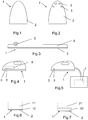
- Irons comprise a sole 1 having a surface of slider 2 provided for ironing, as shown on the figure 1 .
- the sole 1 has orifices 3 provided for the passage of steam, as shown in FIG. figure 2 .
- the sole 1 is associated with a heating body 4 comprising electric heating means 5 as shown in FIG. figure 3 , the orifices 3 not being represented.
- the heating body 4 is advantageously made of aluminum.
- the electric heating means 5 are advantageously formed by a shielded heating element.
- the iron has an internal steam generator 6 connected to the orifices 3 provided for the passage of steam.
- the iron is associated with an external steam generator 7 connected to the orifices 3 provided for the passage of steam.
- the soleplate 1 of iron has a sole body 11, 21 metal having a sliding surface 12, 22 ceramic provided for ironing.
- the metal sole 11, 21 forms a substrate carrying a surface layer of transition metal boride or boronitride forming the sliding surface 12, 22.
- transition metal boride is not limited to stoichiometric compositions having a boron atom for a transition metal atom, but includes transition metal diborides.
- the transition metal is preferably selected from titanium, chromium, zirconium, vanadium, niobium and iron. Borides of transition metals such as titanium, chromium, zirconium, vanadium, niobium are diborides.
- the sole body 11, 21 metal is advantageously made of stainless steel or titanium.
- transition metal boronitride is not limited to stoichiometric compositions comprising a boron atom and an atom nitrogen for a transition metal atom, but includes boronings such as TiAlBN.
- the metal sole body 11, 21 forms a substrate carrying a surface layer of transition metal boride or transition metal boronitride forming the sliding surface 12, 22.
- the invention also relates to irons comprising such a sole 1.
- the surface layer is formed by a transition metal boride or boronitride coating.
- the transition metal boride or boronitride coating is deposited on a substrate formed by the metal sole body 11.
- the surface layer is formed by a transition metal boride or transition metal boronitride coating.
- Transition metal boride coatings such as TiB 2 , CrB 2 , FeB, Fe 2 B, VB 2 , NbB 2 or ZrB 2 are known for their properties of high hardness, resistance to wear and corrosion. and their thermal stability.
- transition metal borides such as TiB 2 , CrB 2 , FeB, Fe 2 B, VB 2 , NbB 2 or ZrB 2 .
- the coating may in particular be made by physical vapor deposition on the outer face of the sole body, or by chemical vapor deposition assisted plasma on the outer face of the sole body.
- PVD physical vapor deposition
- pulsed or non-pulsed DC magnetron cathode sputtering seems to be the most appropriate method for obtaining such coatings because it allows for low-temperature (lower) deposits. at 200 ° C) on parts that may have relatively complex geometries without using toxic gas.
- the deposits obtained are dense and adherent to the substrate. In addition, the surface topography of the substrate is retained.
- Deposits of transition metal borides are obtained from a target having the same composition as that of the target coating, the target can be developed by sintering powder. After obtaining a high vacuum in the chamber, the film is produced by sputtering in a non-reactive condition under argon atmosphere of the target.
- the deposition rates obtained by this technique are of the order of a few ⁇ m / h.
- the thickness of the coating obtained is advantageously between 0.1 and 5 ⁇ m.
- transition metal boride coatings such as radiofrequency cathodic sputtering, reactive medium sputtering with diborane use, or ion beam sputtering.
- radiofrequency cathodic sputtering reactive medium sputtering with diborane use
- ion beam sputtering ion beam sputtering
- the coating could also be made by cathodic arc evaporation on the outer face of the sole body 11.
- Plasma-assisted chemical vapor deposition can also make it possible to obtain relatively low temperature transition metal boride coatings (of the order of 400 ° C.).
- the gases used are BCl 3 , TiCl 4 or Ti (BH 4 ) 4 . This process can thus make it possible to obtain stoichiometric deposits having properties close to those obtained by PVD.
- the tested deposits were developed by PVD technique, using pulsed DC magnetron sputtering of a CrB 2 target under an argon atmosphere.
- the targeted coating thickness is between 0.1 and 5 ⁇ m.
- the coating CrB 2 obtained is adherent, a color almost identical to that of stainless steel.
- the thickness of the deposited coating is 2 ⁇ m.
- the deposits may be obtained by copulverization of a metal target X and a target B 4 C.
- X designating a transition metal or a metal alloy of transition metals such as TiAl, TiCr, ZrNb. .
- the surface layer then contains traces of carbon.
- the sliding coefficients were measured dry on cotton and polyester, according to the IEC 60130 standard, by measuring the horizontal force required to pull the iron resting on a stretched fabric, the sliding coefficient corresponding to the traction force. divided by the weight of the whole moving (iron + support).
- a value of 0.12 was obtained for the temperature of 200 ° C., this value being better than that of a sliding surface made of stainless steel (0.22 to 0.24), and close to that of an enamel sliding surface (0.10).
- a value of 0.20 was obtained, this value being much better than that of an enamel gliding surface (0.30 to 0.40).
- the substrate To obtain a gliding surface 12 having good impact properties and resistance to micro-scratching and / or abrasion, the substrate must have a minimum hardness.
- the transition metal boride coatings have a high hardness (> 2000 HV), the thickness of these coatings can be very small, advantageously between 0.1 and 5 microns.
- a substrate with a minimum hardness of 150 HV must be used to ensure a better resistance to microrayure and / or abrasion of the coating, a too soft substrate such as aluminum not making it possible to exploit the hardness properties and impact resistance provided by a transition metal boride coating.
- a ferritic stainless steel ( ⁇ 160 HV), austenitic stainless steel ( ⁇ 210 HV) or titanium (> 160 HV) substrate can be used in the context of this invention.
- an aluminum substrate 50 to 90 HV does not have sufficient hardness to obtain the desired properties.
- the metal sole body 11 has a hardness greater than or equal to 150 HV.
- the metal sole plate 11 is advantageously made of stainless steel or titanium.
- Transition metal borides have low thermal expansion coefficients ( ⁇ 10 ⁇ 10 -6 K -1 ).
- the substrate must have a coefficient of thermal expansion close to the expansion coefficients of the transition metal borides, in order to eliminate any risk of cracking during the heating of the soleplate, which would degrade the gliding properties of the coating described in FIG. 'invention.
- a metal substrate with a low coefficient of thermal expansion such as ferritic stainless steel ( ⁇ 11. 10 -6 K -1 ), austenitic stainless steel ( ⁇ 16. 10 -6 K -1 ), or titanium ( ⁇ 10. 10 -6 K -1 ) thus makes it possible to avoid this problem of cracking of the coating during the heating of the soleplate.
- the metal soleplate 11 has a coefficient of thermal expansion of less than 20 ⁇ 10 -6. K -1 .
- the thickness of the metal sole body is advantageously of the order of 0.4 mm.
- An iron soleplate having a coating according to the invention has gliding properties significantly greater than that of a stainless steel, and moreover an improved abrasion resistance compared to a stainless steel soleplate.
- XBN-type transition metal boronitride deposits for example TiBN or TiAlBN
- Boronitrides make it possible to obtain a different color from stainless steel, for example dark gray or anthracite for TiBN.
- the surface layer is formed by a conversion layer of iron boride or titanium.
- the conversion layer is produced by boron thermochemical diffusion treatment on a metal substrate formed by the sole body 21.
- Thermochemical diffusion treatments make it possible to enrich the surface of a boron part. These treatments are usually carried out between 800 and 1000 ° C. Homogeneous layers of strongly adherent borides are thus formed on the surface. Different methods can be used to perform such treatments.
- the source gases of boron are boron halides or boranes.
- liquid medium in the presence of molten salts with or without electrolysis, or in aqueous solution of borax.
- a solid medium by case-type cementation method, in which the pieces are placed in a cementum constituted by powder and granules based on boron carbide which is mixed with a fluoroborate acting as an activator.
- the temperature (of the order of 900 ° C.) and the treatment time depend on the thickness of the desired borured zone. Typically, the borured layer thicknesses vary between 10 and 300 ⁇ m. The hardnesses reached depend on the material used. One of the most common applications is for ferrous alloys (especially stainless steels) with a hardness of 1600 to 2000 HV. It is also possible to perform such a boron thermochemical treatment on metals such as titanium (titanium boride layer formation up to 4000 HV) or nickel base alloys (up to 2800 HV).
- the metal sole 21 has a hardness greater than or equal to 150 HV.
- the metal sole body 21 is advantageously made of stainless steel or titanium.
- the method consists in producing a transition metal boride or boronitride coating on the outer face of the sole body 11.
- the method consists in producing a transition metal boride or transition metal boronitride coating on the outer face of the sole body 11.
- the method consists in producing an iron or titanium boride conversion layer by boronization thermochemical diffusion treatment on the outer face of the sole body 11; 21.
- the sliding surface 12, 22 formed by a surface layer of boride or boronitride transition metal is carried by a substrate sufficiently rigid to allow impact resistance as well as resistance to micro scratching and / or satisfactory abrasion.
Landscapes
- Chemical & Material Sciences (AREA)
- Engineering & Computer Science (AREA)
- Metallurgy (AREA)
- Chemical Kinetics & Catalysis (AREA)
- Materials Engineering (AREA)
- Mechanical Engineering (AREA)
- Organic Chemistry (AREA)
- General Chemical & Material Sciences (AREA)
- Inorganic Chemistry (AREA)
- Plasma & Fusion (AREA)
- Physics & Mathematics (AREA)
- Textile Engineering (AREA)
- Physical Vapour Deposition (AREA)
- Irons (AREA)
Claims (19)
- Bügeleisensohle (1) mit einem Metall-Sohlenkörper (11; 21), der eine für das Bügeln vorgesehene Keramik-Gleitfläche (12; 22) aufweist, dadurch gekennzeichnet dass der Sohlenkörper (11;21) eine Härte von mindestens 150 HV hat und ein Substrat bildet, das eine Oberflächenschicht aus dem Borid eines Übergangsmetalls oder dem Bornitrid eines Übergangsmetalls trägt, die die Gleitfläche (12; 22) bildet.
- Bügeleisensohle (1) nach Anspruch 1, dadurch gekennzeichnet, dass der Sohlenkörper (11; 21) einen Wärmeausdehnungskoeffizienten von unter 20·10-6 K-1 aufweist.
- Bügeleisensohle (1) nach einem der Ansprüche 1 oder 2, dadurch gekennzeichnet, dass der Sohlenkörper (11; 21) aus Edelstahl oder Titan hergestellt wird.
- Bügeleisensohle (1) nach einem der Ansprüche 1 bis 3, dadurch gekennzeichnet, dass die Oberflächenschicht durch eine Beschichtung mit dem Borid eines Übergangsmetalls oder dem Bornitrid eines Übergangsmetalls gebildet wird.
- Bügeleisensohle (1) nach Anspruch 4, dadurch gekennzeichnet, dass das Übergangsmetall aus Titan, Chrom, Zirkonium, Vanadium, Niobium und Eisen ausgewählt wird.
- Bügeleisensohle (1) nach einem der Ansprüche 1 oder 2, dadurch gekennzeichnet, dass die Oberflächenschicht durch eine Konversionsschicht aus Eisen- und/oder Titanborid gebildet wird.
- Bügeleisen mit einer Sohle (1), die zu einem Heizelement (4) gehört, das elektrische Heizmittel (5) umfasst, dadurch gekennzeichnet, dass die Sohle (1) einem der Ansprüche 1 bis 6 entspricht.
- Bügeleisen nach Anspruch 7, dadurch gekennzeichnet, dass die Sohle (1) Öffnungen (3) für den Durchtritt von Dampf aufweist.
- Bügeleisen nach Anspruch 8, dadurch gekennzeichnet, dass es einen internen Dampfgenerator (6) aufweist, der mit den Öffnungen (3) für den Durchtritt des Dampfes verbunden ist.
- Bügeleisen nach Anspruch 8, dadurch gekennzeichnet, dass es zu einem externen Dampfgenerator (7) gehört, der mit den Öffnungen (3) für den Durchtritt des Dampfes verbunden ist.
- Verfahren zur Herstellung einer Bügeleisensohle (1), das die folgenden Schritte umfasst:- Bereitstellung oder Herstellung eines Metall-Sohlenkörpers (11; 21) mit einer Härte von mindestens 150 HV,- Aufbringen einer Oberflächenschicht aus dem Borid eines Übergangsmetalls oder dem Bornitrid eines Übergangsmetalls auf der Außenseite des Sohlenkörpers (11; 21), um eine Gleitfläche (12; 22) zu bilden.
- Verfahren zur Herstellung einer Bügeleisensohle (1) nach Anspruch 11, dadurch gekennzeichnet, dass der Sohlenkörper (11; 21) einen Wärmeausdehnungskoeffizienten von unter 20·10-6 K-1 aufweist.
- Verfahren zur Herstellung einer Bügeleisensohle (1) nach einem der Ansprüche 11 oder 12, dadurch gekennzeichnet, dass der Sohlenkörper (11; 21) aus Edelstahl oder Titan hergestellt wird.
- Verfahren zur Herstellung einer Bügeleisensohle (1) nach einem der Ansprüche 11 bis 13, dadurch gekennzeichnet, dass es darin besteht, auf der Außenseite des Sohlenkörpers (11) eine Beschichtung aus dem Borid eines Übergangsmetalls oder dem Bornitrid eines Übergangsmetalls aufzubringen.
- Verfahren zur Herstellung einer Bügeleisensohle (1) nach Anspruch 14, dadurch gekennzeichnet, dass das Übergangsmetall aus Titan, Chrom, Zirkonium, Vanadium, Niobium und Eisen ausgewählt wird.
- Verfahren zur Herstellung einer Bügeleisensohle (1) nach einem der Ansprüche 14 oder 15, dadurch gekennzeichnet, dass die Beschichtung durch physikalische Gasphasenabscheidung auf der Außenseite des Sohlenkörpers (11) erfolgt.
- Verfahren zur Herstellung einer Bügeleisensohle (1) nach Anspruch 16, dadurch gekennzeichnet, dass die Abscheidung durch Magnetron-Kathodenzerstäubung mit Gleichstrom, vorzugsweise pulsierendem Gleichstrom, erfolgt.
- Verfahren zur Herstellung einer Bügeleisensohle (1) nach einem der Ansprüche 14 oder 15, dadurch gekennzeichnet, dass die Beschichtung durch plasmaunterstützte chemische Gasphasenabscheidung auf der Außenseite des Sohlenkörpers (11) erfolgt.
- Verfahren zur Herstellung einer Bügeleisensohle (1) nach einem der Ansprüche 11 bis 13, dadurch gekennzeichnet, dass es darin besteht, durch eine thermochemische Diffusionsbehandlung des Borierens auf der Außenseite des Sohlenkörpers (21) eine Konversionsschicht aus Eisen- oder Titanborid aufzubringen.
Applications Claiming Priority (2)
| Application Number | Priority Date | Filing Date | Title |
|---|---|---|---|
| FR1261227A FR2998587B1 (fr) | 2012-11-26 | 2012-11-26 | Semelle de fer a repasser presentant des proprietes de glisse et de resistance a l'abrasion ameliorees |
| PCT/EP2013/074506 WO2014079982A1 (fr) | 2012-11-26 | 2013-11-22 | Semelle de fer a repasser presentant des proprietes de glisse et de resistance a l'abrasion ameliorees |
Publications (2)
| Publication Number | Publication Date |
|---|---|
| EP2929079A1 EP2929079A1 (de) | 2015-10-14 |
| EP2929079B1 true EP2929079B1 (de) | 2017-01-18 |
Family
ID=47833192
Family Applications (1)
| Application Number | Title | Priority Date | Filing Date |
|---|---|---|---|
| EP13795235.4A Active EP2929079B1 (de) | 2012-11-26 | 2013-11-22 | Bügeleisensohle mit verbesserten gleit- und reibwiderstandseigenschaften |
Country Status (4)
| Country | Link |
|---|---|
| EP (1) | EP2929079B1 (de) |
| CN (1) | CN104937161B (de) |
| FR (1) | FR2998587B1 (de) |
| WO (1) | WO2014079982A1 (de) |
Families Citing this family (2)
| Publication number | Priority date | Publication date | Assignee | Title |
|---|---|---|---|---|
| EP3222770A1 (de) * | 2016-03-21 | 2017-09-27 | Koninklijke Philips N.V. | Behandlungsplatte für eine kleidungsbehandlungsanwendung |
| US11891752B2 (en) | 2021-01-05 | 2024-02-06 | Pierre Romain | Microwavable material smoothing apparatus |
Family Cites Families (14)
| Publication number | Priority date | Publication date | Assignee | Title |
|---|---|---|---|---|
| JPS564345A (en) * | 1979-06-25 | 1981-01-17 | Kawasaki Heavy Ind Ltd | Production of metal mold for shell mold |
| US4665637A (en) * | 1985-07-26 | 1987-05-19 | Braun Aktiengesellschaft | Sole plate coating for a fabric pressing device |
| DE4411790A1 (de) * | 1994-04-06 | 1995-10-12 | Braun Ag | Elektrisches Bügeleisen |
| BE1008961A3 (nl) * | 1994-11-14 | 1996-10-01 | Philips Electronics Nv | Strijkijzer met glijlaag. |
| CN1083036C (zh) * | 1996-09-24 | 2002-04-17 | 皇家菲利浦电子有限公司 | 熨斗和熨斗用底板 |
| DE19909887A1 (de) * | 1998-04-03 | 1999-10-07 | Wella Ag | Verfahren zum Herstellen von Gleitflächen und/oder Scherkanten aus Hartwerkstoff auf einem Grundwerkstoff sowie eine nach diesem Verfahren hergestellte Gleitfläche und/oder Scherkante |
| SG91330A1 (en) * | 2001-02-17 | 2002-09-17 | Gintic Inst Of Mfg Technology | Iron and sole plate for an iron |
| US7268190B2 (en) * | 2001-08-03 | 2007-09-11 | Toray Industries, Inc. | Resin composition comprising polylactic acid and polyacetal and a molded article, film, and fiber each comprising the same |
| FR2837220B1 (fr) * | 2002-03-13 | 2004-08-06 | Rowenta Werke Gmbh | Semelle de fer a surface durcie et revetue |
| US20070036900A1 (en) * | 2005-08-12 | 2007-02-15 | Yuqing Liu | Process for improving the corrosion resistance of a non-stick coating on a substrate |
| US7695807B2 (en) * | 2006-04-04 | 2010-04-13 | E.I. Du Pont De Nemours And Company | Non-stick finish |
| CN201272921Y (zh) * | 2008-09-09 | 2009-07-15 | 张建杰 | 一种电熨斗底板 |
| GB2479803B8 (en) * | 2010-11-17 | 2013-10-23 | Richards Morphy N I Ltd | Iron sole plate |
| CN202047287U (zh) * | 2011-03-28 | 2011-11-23 | 上海宜瓷龙新材料科技有限公司 | 一种涂有耐温耐磨高硬度低摩擦系数涂料的电熨斗底板 |
-
2012
- 2012-11-26 FR FR1261227A patent/FR2998587B1/fr active Active
-
2013
- 2013-11-22 WO PCT/EP2013/074506 patent/WO2014079982A1/fr not_active Ceased
- 2013-11-22 CN CN201380061020.3A patent/CN104937161B/zh active Active
- 2013-11-22 EP EP13795235.4A patent/EP2929079B1/de active Active
Non-Patent Citations (1)
| Title |
|---|
| None * |
Also Published As
| Publication number | Publication date |
|---|---|
| EP2929079A1 (de) | 2015-10-14 |
| WO2014079982A1 (fr) | 2014-05-30 |
| CN104937161B (zh) | 2016-12-14 |
| WO2014079982A4 (fr) | 2014-08-21 |
| FR2998587A1 (fr) | 2014-05-30 |
| CN104937161A (zh) | 2015-09-23 |
| FR2998587B1 (fr) | 2015-05-22 |
Similar Documents
| Publication | Publication Date | Title |
|---|---|---|
| Zou et al. | Effects of Cr concentrations on the microstructure, hardness, and temperature-dependent tribological properties of Cr-DLC coatings | |
| JP4085699B2 (ja) | 摺動部材及びその製造方法 | |
| Zhang et al. | A new method to improve the tribological performance of metal nitride coating: A case study for CrN coating | |
| Yang et al. | Catalytic growth of diamond-like carbon on Fe3C-containing carburized layer through a single-step plasma-assisted carburizing process | |
| FR2576608A1 (fr) | Procede pour revetir des elements de machines ou outils d'une matiere dure et elements de machines et outils fabriques par application de ce procede | |
| Zhang et al. | Effect of plasma nitriding ion current density on tribological properties of composite CrAlN coatings | |
| Zou et al. | The microstructure, mechanical and friction properties of protective diamond like carbon films on magnesium alloy | |
| Meškinis et al. | Bias effects on structure and piezoresistive properties of DLC: Ag thin films | |
| EP0010484B1 (de) | Verbesserung der Inchromierung von Stahl in der Gasphase | |
| Libório et al. | Enhanced surface properties of M2 steel by plasma nitriding pre-treatment and magnetron sputtered TiN coating | |
| TW201339331A (zh) | 鍍膜件及其製備方法 | |
| Lin et al. | RECENT DEVELOPMENTS IN IMPROVING TRIBOLOGICAL PERFORMANCE OF TC4 TITANIUM ALLOY VIA DOUBLE GLOW PLASMA SURFACE ALLOYING IN CHINA: A LITERATURE REVIEW. | |
| Ghasemi et al. | A comparative study of duty cycle and argon/methane flow ratio effect on the tribological behavior of DLC coatings over nitrided Astaloy Mo-based steel | |
| EP2929079A1 (de) | Sohle eines bügeleisens mit verbesserten gleit- und abriebfestigkeitseigenschaften | |
| FR2722800A1 (fr) | Produits composites en acier revetus en double couche et leur procede de fabrication | |
| JP5720996B2 (ja) | 皮膜密着性に優れた被覆部材およびその製造方法 | |
| Baggio-Scheid et al. | Duplex surface treatment of chromium pack diffusion and plasma nitriding of mild steel | |
| JP5129009B2 (ja) | 金型用被膜 | |
| Prakash et al. | Ti–B and Ti–B–C coatings deposited by plasma immersion ion implantation and their fretting behavior | |
| CA2892446C (fr) | Dispositif de cuisson comportant une surface de cuisson facile a nettoyer et resistant a la rayure | |
| Shaik et al. | Influence of Si–C bond density on the properties of a-Si1− xCx thin films | |
| Pérez-Alvarez et al. | Effect of a-CNx top layer on the electrochemical properties of Ta2N/Ta multilayers obtained by HIPIMS | |
| EP2867385B1 (de) | Verfahren zur abscheidung einer dekorativen und schützenden beschichtung | |
| Konstantinov et al. | Effect of argon and nitrogen environments on the structure and properties of protective cermet coatings based on titanium borides obtained by electric arc surfacing | |
| Colomer et al. | Vertically aligned carbon nanotubes: Synthesis and atomic oxygen functionalization |
Legal Events
| Date | Code | Title | Description |
|---|---|---|---|
| PUAI | Public reference made under article 153(3) epc to a published international application that has entered the european phase |
Free format text: ORIGINAL CODE: 0009012 |
|
| 17P | Request for examination filed |
Effective date: 20150625 |
|
| AK | Designated contracting states |
Kind code of ref document: A1 Designated state(s): AL AT BE BG CH CY CZ DE DK EE ES FI FR GB GR HR HU IE IS IT LI LT LU LV MC MK MT NL NO PL PT RO RS SE SI SK SM TR |
|
| AX | Request for extension of the european patent |
Extension state: BA ME |
|
| DAX | Request for extension of the european patent (deleted) | ||
| GRAP | Despatch of communication of intention to grant a patent |
Free format text: ORIGINAL CODE: EPIDOSNIGR1 |
|
| INTG | Intention to grant announced |
Effective date: 20160810 |
|
| RAP1 | Party data changed (applicant data changed or rights of an application transferred) |
Owner name: SEB S.A. Owner name: CNRS - CENTRE NATIONAL DE LA RECHERCHE SCIENTIFIQU Owner name: UNIVERSITE DE LORRAINE |
|
| RIN1 | Information on inventor provided before grant (corrected) |
Inventor name: PIERSON, JEAN-FRANCOIS Inventor name: ALLEMAND, SIMON Inventor name: PACCAUD, DENIS Inventor name: TUFFE, STEPHANE |
|
| RAP1 | Party data changed (applicant data changed or rights of an application transferred) |
Owner name: SEB S.A. Owner name: UNIVERSITE DE LORRAINE Owner name: CNRS - CENTRE NATIONAL DE LA RECHERCHE SCIENTIFIQU |
|
| GRAS | Grant fee paid |
Free format text: ORIGINAL CODE: EPIDOSNIGR3 |
|
| GRAA | (expected) grant |
Free format text: ORIGINAL CODE: 0009210 |
|
| AK | Designated contracting states |
Kind code of ref document: B1 Designated state(s): AL AT BE BG CH CY CZ DE DK EE ES FI FR GB GR HR HU IE IS IT LI LT LU LV MC MK MT NL NO PL PT RO RS SE SI SK SM TR |
|
| REG | Reference to a national code |
Ref country code: GB Ref legal event code: FG4D Free format text: NOT ENGLISH |
|
| REG | Reference to a national code |
Ref country code: CH Ref legal event code: EP |
|
| REG | Reference to a national code |
Ref country code: AT Ref legal event code: REF Ref document number: 862990 Country of ref document: AT Kind code of ref document: T Effective date: 20170215 |
|
| REG | Reference to a national code |
Ref country code: IE Ref legal event code: FG4D Free format text: LANGUAGE OF EP DOCUMENT: FRENCH |
|
| REG | Reference to a national code |
Ref country code: DE Ref legal event code: R096 Ref document number: 602013016799 Country of ref document: DE |
|
| REG | Reference to a national code |
Ref country code: NL Ref legal event code: MP Effective date: 20170118 |
|
| REG | Reference to a national code |
Ref country code: LT Ref legal event code: MG4D |
|
| REG | Reference to a national code |
Ref country code: AT Ref legal event code: MK05 Ref document number: 862990 Country of ref document: AT Kind code of ref document: T Effective date: 20170118 |
|
| PG25 | Lapsed in a contracting state [announced via postgrant information from national office to epo] |
Ref country code: NL Free format text: LAPSE BECAUSE OF FAILURE TO SUBMIT A TRANSLATION OF THE DESCRIPTION OR TO PAY THE FEE WITHIN THE PRESCRIBED TIME-LIMIT Effective date: 20170118 |
|
| PG25 | Lapsed in a contracting state [announced via postgrant information from national office to epo] |
Ref country code: FI Free format text: LAPSE BECAUSE OF FAILURE TO SUBMIT A TRANSLATION OF THE DESCRIPTION OR TO PAY THE FEE WITHIN THE PRESCRIBED TIME-LIMIT Effective date: 20170118 Ref country code: LT Free format text: LAPSE BECAUSE OF FAILURE TO SUBMIT A TRANSLATION OF THE DESCRIPTION OR TO PAY THE FEE WITHIN THE PRESCRIBED TIME-LIMIT Effective date: 20170118 Ref country code: GR Free format text: LAPSE BECAUSE OF FAILURE TO SUBMIT A TRANSLATION OF THE DESCRIPTION OR TO PAY THE FEE WITHIN THE PRESCRIBED TIME-LIMIT Effective date: 20170419 Ref country code: HR Free format text: LAPSE BECAUSE OF FAILURE TO SUBMIT A TRANSLATION OF THE DESCRIPTION OR TO PAY THE FEE WITHIN THE PRESCRIBED TIME-LIMIT Effective date: 20170118 Ref country code: NO Free format text: LAPSE BECAUSE OF FAILURE TO SUBMIT A TRANSLATION OF THE DESCRIPTION OR TO PAY THE FEE WITHIN THE PRESCRIBED TIME-LIMIT Effective date: 20170418 Ref country code: IS Free format text: LAPSE BECAUSE OF FAILURE TO SUBMIT A TRANSLATION OF THE DESCRIPTION OR TO PAY THE FEE WITHIN THE PRESCRIBED TIME-LIMIT Effective date: 20170518 |
|
| PG25 | Lapsed in a contracting state [announced via postgrant information from national office to epo] |
Ref country code: LV Free format text: LAPSE BECAUSE OF FAILURE TO SUBMIT A TRANSLATION OF THE DESCRIPTION OR TO PAY THE FEE WITHIN THE PRESCRIBED TIME-LIMIT Effective date: 20170118 Ref country code: AT Free format text: LAPSE BECAUSE OF FAILURE TO SUBMIT A TRANSLATION OF THE DESCRIPTION OR TO PAY THE FEE WITHIN THE PRESCRIBED TIME-LIMIT Effective date: 20170118 Ref country code: RS Free format text: LAPSE BECAUSE OF FAILURE TO SUBMIT A TRANSLATION OF THE DESCRIPTION OR TO PAY THE FEE WITHIN THE PRESCRIBED TIME-LIMIT Effective date: 20170118 Ref country code: PL Free format text: LAPSE BECAUSE OF FAILURE TO SUBMIT A TRANSLATION OF THE DESCRIPTION OR TO PAY THE FEE WITHIN THE PRESCRIBED TIME-LIMIT Effective date: 20170118 Ref country code: PT Free format text: LAPSE BECAUSE OF FAILURE TO SUBMIT A TRANSLATION OF THE DESCRIPTION OR TO PAY THE FEE WITHIN THE PRESCRIBED TIME-LIMIT Effective date: 20170518 Ref country code: SE Free format text: LAPSE BECAUSE OF FAILURE TO SUBMIT A TRANSLATION OF THE DESCRIPTION OR TO PAY THE FEE WITHIN THE PRESCRIBED TIME-LIMIT Effective date: 20170118 Ref country code: ES Free format text: LAPSE BECAUSE OF FAILURE TO SUBMIT A TRANSLATION OF THE DESCRIPTION OR TO PAY THE FEE WITHIN THE PRESCRIBED TIME-LIMIT Effective date: 20170118 Ref country code: BG Free format text: LAPSE BECAUSE OF FAILURE TO SUBMIT A TRANSLATION OF THE DESCRIPTION OR TO PAY THE FEE WITHIN THE PRESCRIBED TIME-LIMIT Effective date: 20170418 |
|
| REG | Reference to a national code |
Ref country code: DE Ref legal event code: R097 Ref document number: 602013016799 Country of ref document: DE |
|
| PG25 | Lapsed in a contracting state [announced via postgrant information from national office to epo] |
Ref country code: CZ Free format text: LAPSE BECAUSE OF FAILURE TO SUBMIT A TRANSLATION OF THE DESCRIPTION OR TO PAY THE FEE WITHIN THE PRESCRIBED TIME-LIMIT Effective date: 20170118 Ref country code: RO Free format text: LAPSE BECAUSE OF FAILURE TO SUBMIT A TRANSLATION OF THE DESCRIPTION OR TO PAY THE FEE WITHIN THE PRESCRIBED TIME-LIMIT Effective date: 20170118 Ref country code: SK Free format text: LAPSE BECAUSE OF FAILURE TO SUBMIT A TRANSLATION OF THE DESCRIPTION OR TO PAY THE FEE WITHIN THE PRESCRIBED TIME-LIMIT Effective date: 20170118 Ref country code: EE Free format text: LAPSE BECAUSE OF FAILURE TO SUBMIT A TRANSLATION OF THE DESCRIPTION OR TO PAY THE FEE WITHIN THE PRESCRIBED TIME-LIMIT Effective date: 20170118 Ref country code: IT Free format text: LAPSE BECAUSE OF FAILURE TO SUBMIT A TRANSLATION OF THE DESCRIPTION OR TO PAY THE FEE WITHIN THE PRESCRIBED TIME-LIMIT Effective date: 20170118 |
|
| PLBE | No opposition filed within time limit |
Free format text: ORIGINAL CODE: 0009261 |
|
| STAA | Information on the status of an ep patent application or granted ep patent |
Free format text: STATUS: NO OPPOSITION FILED WITHIN TIME LIMIT |
|
| PG25 | Lapsed in a contracting state [announced via postgrant information from national office to epo] |
Ref country code: SM Free format text: LAPSE BECAUSE OF FAILURE TO SUBMIT A TRANSLATION OF THE DESCRIPTION OR TO PAY THE FEE WITHIN THE PRESCRIBED TIME-LIMIT Effective date: 20170118 Ref country code: DK Free format text: LAPSE BECAUSE OF FAILURE TO SUBMIT A TRANSLATION OF THE DESCRIPTION OR TO PAY THE FEE WITHIN THE PRESCRIBED TIME-LIMIT Effective date: 20170118 |
|
| REG | Reference to a national code |
Ref country code: FR Ref legal event code: PLFP Year of fee payment: 5 |
|
| 26N | No opposition filed |
Effective date: 20171019 |
|
| PG25 | Lapsed in a contracting state [announced via postgrant information from national office to epo] |
Ref country code: SI Free format text: LAPSE BECAUSE OF FAILURE TO SUBMIT A TRANSLATION OF THE DESCRIPTION OR TO PAY THE FEE WITHIN THE PRESCRIBED TIME-LIMIT Effective date: 20170118 |
|
| PG25 | Lapsed in a contracting state [announced via postgrant information from national office to epo] |
Ref country code: MC Free format text: LAPSE BECAUSE OF FAILURE TO SUBMIT A TRANSLATION OF THE DESCRIPTION OR TO PAY THE FEE WITHIN THE PRESCRIBED TIME-LIMIT Effective date: 20170118 |
|
| PG25 | Lapsed in a contracting state [announced via postgrant information from national office to epo] |
Ref country code: LI Free format text: LAPSE BECAUSE OF NON-PAYMENT OF DUE FEES Effective date: 20171130 Ref country code: CH Free format text: LAPSE BECAUSE OF NON-PAYMENT OF DUE FEES Effective date: 20171130 |
|
| PG25 | Lapsed in a contracting state [announced via postgrant information from national office to epo] |
Ref country code: LU Free format text: LAPSE BECAUSE OF NON-PAYMENT OF DUE FEES Effective date: 20171122 |
|
| REG | Reference to a national code |
Ref country code: BE Ref legal event code: MM Effective date: 20171130 |
|
| REG | Reference to a national code |
Ref country code: IE Ref legal event code: MM4A |
|
| PG25 | Lapsed in a contracting state [announced via postgrant information from national office to epo] |
Ref country code: MT Free format text: LAPSE BECAUSE OF FAILURE TO SUBMIT A TRANSLATION OF THE DESCRIPTION OR TO PAY THE FEE WITHIN THE PRESCRIBED TIME-LIMIT Effective date: 20170118 |
|
| PG25 | Lapsed in a contracting state [announced via postgrant information from national office to epo] |
Ref country code: IE Free format text: LAPSE BECAUSE OF NON-PAYMENT OF DUE FEES Effective date: 20171122 |
|
| PG25 | Lapsed in a contracting state [announced via postgrant information from national office to epo] |
Ref country code: BE Free format text: LAPSE BECAUSE OF NON-PAYMENT OF DUE FEES Effective date: 20171130 |
|
| PG25 | Lapsed in a contracting state [announced via postgrant information from national office to epo] |
Ref country code: HU Free format text: LAPSE BECAUSE OF FAILURE TO SUBMIT A TRANSLATION OF THE DESCRIPTION OR TO PAY THE FEE WITHIN THE PRESCRIBED TIME-LIMIT; INVALID AB INITIO Effective date: 20131122 |
|
| PG25 | Lapsed in a contracting state [announced via postgrant information from national office to epo] |
Ref country code: CY Free format text: LAPSE BECAUSE OF FAILURE TO SUBMIT A TRANSLATION OF THE DESCRIPTION OR TO PAY THE FEE WITHIN THE PRESCRIBED TIME-LIMIT Effective date: 20170118 |
|
| PG25 | Lapsed in a contracting state [announced via postgrant information from national office to epo] |
Ref country code: MK Free format text: LAPSE BECAUSE OF FAILURE TO SUBMIT A TRANSLATION OF THE DESCRIPTION OR TO PAY THE FEE WITHIN THE PRESCRIBED TIME-LIMIT Effective date: 20170118 |
|
| PG25 | Lapsed in a contracting state [announced via postgrant information from national office to epo] |
Ref country code: TR Free format text: LAPSE BECAUSE OF FAILURE TO SUBMIT A TRANSLATION OF THE DESCRIPTION OR TO PAY THE FEE WITHIN THE PRESCRIBED TIME-LIMIT Effective date: 20170118 |
|
| PG25 | Lapsed in a contracting state [announced via postgrant information from national office to epo] |
Ref country code: AL Free format text: LAPSE BECAUSE OF FAILURE TO SUBMIT A TRANSLATION OF THE DESCRIPTION OR TO PAY THE FEE WITHIN THE PRESCRIBED TIME-LIMIT Effective date: 20170118 |
|
| PGFP | Annual fee paid to national office [announced via postgrant information from national office to epo] |
Ref country code: DE Payment date: 20241108 Year of fee payment: 12 |
|
| PGFP | Annual fee paid to national office [announced via postgrant information from national office to epo] |
Ref country code: GB Payment date: 20241122 Year of fee payment: 12 |
|
| PGFP | Annual fee paid to national office [announced via postgrant information from national office to epo] |
Ref country code: FR Payment date: 20241120 Year of fee payment: 12 |