EP2928710B1 - Method for operating a refrigerant circuit as a heat pump - Google Patents
Method for operating a refrigerant circuit as a heat pump Download PDFInfo
- Publication number
- EP2928710B1 EP2928710B1 EP13786499.7A EP13786499A EP2928710B1 EP 2928710 B1 EP2928710 B1 EP 2928710B1 EP 13786499 A EP13786499 A EP 13786499A EP 2928710 B1 EP2928710 B1 EP 2928710B1
- Authority
- EP
- European Patent Office
- Prior art keywords
- refrigerant
- heat
- exchanger device
- expansion member
- compressor
- Prior art date
- Legal status (The legal status is an assumption and is not a legal conclusion. Google has not performed a legal analysis and makes no representation as to the accuracy of the status listed.)
- Active
Links
- 239000003507 refrigerant Substances 0.000 title claims description 215
- 238000000034 method Methods 0.000 title claims description 20
- 238000010438 heat treatment Methods 0.000 claims description 47
- 239000007788 liquid Substances 0.000 claims description 27
- XLYOFNOQVPJJNP-UHFFFAOYSA-N water Substances O XLYOFNOQVPJJNP-UHFFFAOYSA-N 0.000 claims description 6
- 230000001105 regulatory effect Effects 0.000 claims description 5
- 230000001276 controlling effect Effects 0.000 claims description 4
- 239000003570 air Substances 0.000 description 17
- 239000012530 fluid Substances 0.000 description 5
- 238000011161 development Methods 0.000 description 4
- 230000018109 developmental process Effects 0.000 description 4
- 238000004891 communication Methods 0.000 description 3
- 238000001816 cooling Methods 0.000 description 3
- 238000010586 diagram Methods 0.000 description 3
- CURLTUGMZLYLDI-UHFFFAOYSA-N Carbon dioxide Chemical compound O=C=O CURLTUGMZLYLDI-UHFFFAOYSA-N 0.000 description 2
- FNYLWPVRPXGIIP-UHFFFAOYSA-N Triamterene Chemical compound NC1=NC2=NC(N)=NC(N)=C2N=C1C1=CC=CC=C1 FNYLWPVRPXGIIP-UHFFFAOYSA-N 0.000 description 2
- 239000012080 ambient air Substances 0.000 description 2
- 230000005494 condensation Effects 0.000 description 2
- 238000009833 condensation Methods 0.000 description 2
- 238000011217 control strategy Methods 0.000 description 2
- 239000002826 coolant Substances 0.000 description 2
- 238000013021 overheating Methods 0.000 description 2
- 238000004378 air conditioning Methods 0.000 description 1
- 239000003990 capacitor Substances 0.000 description 1
- 229910002092 carbon dioxide Inorganic materials 0.000 description 1
- 239000001569 carbon dioxide Substances 0.000 description 1
- 230000001419 dependent effect Effects 0.000 description 1
- 238000013461 design Methods 0.000 description 1
- 210000000056 organ Anatomy 0.000 description 1
- 238000012546 transfer Methods 0.000 description 1
Images


Classifications
-
- F—MECHANICAL ENGINEERING; LIGHTING; HEATING; WEAPONS; BLASTING
- F25—REFRIGERATION OR COOLING; COMBINED HEATING AND REFRIGERATION SYSTEMS; HEAT PUMP SYSTEMS; MANUFACTURE OR STORAGE OF ICE; LIQUEFACTION SOLIDIFICATION OF GASES
- F25B—REFRIGERATION MACHINES, PLANTS OR SYSTEMS; COMBINED HEATING AND REFRIGERATION SYSTEMS; HEAT PUMP SYSTEMS
- F25B30/00—Heat pumps
- F25B30/02—Heat pumps of the compression type
-
- B—PERFORMING OPERATIONS; TRANSPORTING
- B60—VEHICLES IN GENERAL
- B60H—ARRANGEMENTS OF HEATING, COOLING, VENTILATING OR OTHER AIR-TREATING DEVICES SPECIALLY ADAPTED FOR PASSENGER OR GOODS SPACES OF VEHICLES
- B60H1/00—Heating, cooling or ventilating [HVAC] devices
- B60H1/00642—Control systems or circuits; Control members or indication devices for heating, cooling or ventilating devices
- B60H1/00814—Control systems or circuits characterised by their output, for controlling particular components of the heating, cooling or ventilating installation
- B60H1/00878—Control systems or circuits characterised by their output, for controlling particular components of the heating, cooling or ventilating installation the components being temperature regulating devices
- B60H1/00899—Controlling the flow of liquid in a heat pump system
- B60H1/00914—Controlling the flow of liquid in a heat pump system where the flow direction of the refrigerant does not change and there is a bypass of the condenser
-
- B—PERFORMING OPERATIONS; TRANSPORTING
- B60—VEHICLES IN GENERAL
- B60H—ARRANGEMENTS OF HEATING, COOLING, VENTILATING OR OTHER AIR-TREATING DEVICES SPECIALLY ADAPTED FOR PASSENGER OR GOODS SPACES OF VEHICLES
- B60H1/00—Heating, cooling or ventilating [HVAC] devices
- B60H1/00642—Control systems or circuits; Control members or indication devices for heating, cooling or ventilating devices
- B60H1/00814—Control systems or circuits characterised by their output, for controlling particular components of the heating, cooling or ventilating installation
- B60H1/00878—Control systems or circuits characterised by their output, for controlling particular components of the heating, cooling or ventilating installation the components being temperature regulating devices
- B60H2001/00928—Control systems or circuits characterised by their output, for controlling particular components of the heating, cooling or ventilating installation the components being temperature regulating devices comprising a secondary circuit
Definitions
- the present invention relates to a method for operating a refrigerant circuit as a heat pump according to the preamble of claim 1 and a refrigerant circuit operable as a heat pump according to the preamble of claim 17.
- a method according to the preamble of claim 1 is known from JP H 10297270 A known.
- the technical background of the invention include the FR 2 969 042 A1 as well as the JP 2004 182204 A ,
- the object of the invention is to provide a method for operating a refrigerant circuit, which allows a sufficiently high heat output even at low outdoor temperatures, and to provide a correspondingly suitable refrigerant circuit.
- the starting point of the invention is the idea to ensure by the design of the refrigerant circuit and by a suitable operating strategy that (in particular at low outside temperatures) the refrigerant mass flow drawn in and compressed by the refrigerant compressor or the density of the refrigerant conveyed by the refrigerant compressor is as high as possible.
- the refrigerant mass flow depends not only on the refrigerant volume flow of the compressor, but also on the density of the refrigerant at the inlet of the refrigerant compressor.
- the refrigerant flow can not be increased arbitrarily, otherwise the temperature at the evaporator or at the evaporators of the refrigerant circuit would decrease too much.
- the present invention solves both problems.
- a refrigerant circuit includes a refrigerant compressor that draws refrigerant, compresses, and pumps through a "refrigerant / heating heat exchange device” or additional a condenser / gas cooler in the air conditioner.
- the "refrigerant / heating heat exchange device” may be a "refrigerant / liquid heat exchange device”. be transmitted via the heat from the refrigerant to a liquid circulated in a heating circuit, or a "refrigerant / air heat exchange means", transfer the heat from the refrigerant (without an intermediate fluid flowed through the heating circuit) to the air flowing into a passenger compartment becomes.
- Refrigerant coming from the refrigerant / heater core is depressurized in at least one first expansion device.
- the expanded refrigerant flows through at least one evaporator of the refrigerant circuit and flows from there back toward a suction inlet of the compressor.
- the at least one evaporator can be, for example, an ambient heat exchanger that absorbs heat from the ambient air.
- a plurality of evaporators may also be provided, e.g. an evaporator comprising a vehicle component, e.g. a high-voltage storage or similar, cools.
- the gist of the invention is that refrigerant is branched off at a branch point of the refrigerant heat exchanger heat exchanger device located between a refrigerant inlet and a refrigerant outlet of the refrigerant / heating heat exchanger device and conducted via a second expansion device in the direction of the suction inlet.
- the refrigerant / Walkerungsutzleyer may be a refrigerant / liquid heat exchanger means which cools the refrigerant and possibly also condenses, wherein the heat transferred to heat the interior via a heating circuit is used with a heating heat exchanger in the air conditioner.
- the refrigerant / heating heat exchanger device may be a refrigerant - air heat exchanger device which cools the refrigerant and possibly also condenses, this heat for heating the interior directly used in the air conditioner.
- the refrigerant takes place in the refrigerant / Walkerungskorleyer adopted only a cooling of the refrigerant or in addition a condensation.
- the refrigerant mass flow coming from the at least one evaporator can thus be admixed with a refrigerant mass flow which is branched off from the branch point of the refrigerant / heating heat exchanger device.
- the density of the refrigerant drawn in by the refrigerant compressor or the refrigerant mass flow can be adjusted or regulated in such a way that the highest possible heating power results even at low outside temperatures.
- a second expansion element is provided in the section of the refrigerant circuit which is located between the branch point of the refrigerant / heating heat exchanger device and the suction inlet of the refrigerant compressor.
- the refrigerant / heating heat exchanger device may be conceptually divided into a "first section" extending from the refrigerant inlet to the branch point.
- first section the refrigerant compressed and heated by the refrigerant compressor is cooled, and it may be provided that it is gaseous, i.e., gaseous, over the entire first section. overheated, remains.
- the first portion of the refrigerant / heater core may be referred to as a "desuperheater" through which gaseous refrigerant is cooled.
- a "second portion" of the refrigerant / heating heat exchange device is formed by the portion located between the branch point and the refrigerant outlet.
- the refrigerant continues to give off heat and condense depending on the refrigerant or is supercritically cooled further.
- the second section could be called “capacitor or Gas cooler "are designated by the coming of the first section, gaseous refrigerant is completely or partially condensed or cooled supercritically.
- the refrigerant circuit is thermally coupled via the refrigerant / heating heat exchanger device (in this context refrigerant / liquid heat exchanger device) with a heating circuit through which liquid flows.
- the refrigerant / liquid heat exchanger device may be a heat exchanger device through which refrigerant and liquid flow in countercurrent (countercurrent heat exchanger).
- the above-mentioned desuperheater section and the condenser or gas cooler section may be formed by two sections of a single countercurrent heat exchanger. Alternatively, the desuperheater and the condenser or gas cooler may also be formed by two separate, countercurrent heat exchangers connected in series.
- the heating circuit has a coolant or water pump, the two sections (desuperheater section and condenser or gas cooler section) of the refrigerant / liquid heat exchanger device and a heating heat exchanger.
- the heater core normally located in the air conditioner, is a liquid / air heat exchanger through which heat from the liquid or water to the air flowing into a passenger compartment of a vehicle can be released.
- the refrigerant / Walkerungskorleyer worn is designed as a refrigerant / air heat exchange device.
- the refrigerant circuit is here, the heating heat through the refrigerant / air heat exchanger device, which is normally located in the air conditioner, directly to the in a passenger compartment of a vehicle incoming air from.
- the two parts of the refrigerant / air heat exchanger means may be connected in series on the air side, wherein preferably the first part is flowed through on the air side of the second part.
- a further branch point is provided between the refrigerant / heating heat exchanger device and the at least one first expansion element, which is in fluid communication with the suction inlet of the refrigerant compressor via a third expansion element.
- the second and / or the third expansion element may preferably be controllable expansion elements.
- it can also be simple expansion organs with a fixed flow cross-section, which can be opened or closed respectively.
- FIG. 1 shows a refrigerant circuit 10 having a refrigerant compressor 11.
- the refrigerant compressor 11 sucks refrigerant via a suction inlet 12, compresses it and pumps the compressed refrigerant via a pressure outlet 13 to a refrigerant / liquid heat exchanger device 14.
- the refrigerant / liquid heat exchanger device 14 is formed by two series-connected countercurrent heat exchangers 15, 16. Via the refrigerant / liquid heat exchanger device 14, the refrigerant circuit 10 is thermally coupled to a heating circuit 17.
- the heating circuit 17 has a water pump 18 which pumps heating fluid or water counter to the flow direction of the refrigerant first through the heat exchanger 16 and then through the heat exchanger 15 and finally through a heating heat exchanger 19. Heat can be released from the refrigerant compressed by the refrigerant compressor 11 to the liquid circulated in the heating circuit 17 via the coolant-liquid heat exchanger device 14. Heat from the liquid circulated in the heating circuit 17 can be released via the heating heat exchanger 19 to an air 20 which is to be injected into a passenger compartment of a vehicle and which flows through and / or around the heating heat exchanger 19.
- the heat exchanger 15 acts as a desuperheater
- the series-connected heat exchanger 16 acts as a condenser or in a refrigerant in supercritical operation as a gas cooler.
- Refrigerant which has been compressed and heated by the refrigerant compressor 11, first gives off heat via the heat exchanger 15.
- the refrigerant remains in the gaseous state, but cools down.
- the refrigerant cooled further and depending on the refrigerant while partially or completely condensed or cooled supercritical.
- the coolant / liquid heat exchanger device 14 has a refrigerant inlet 21, a refrigerant outlet 22 and a branching point 23.
- the branch point 23 is, viewed in the flow direction of the refrigerant, between the refrigerant inlet 21 and the refrigerant outlet 22.
- the branch point 23 is located between the two heat exchangers 15, 16.
- the "desuperheater section 15" and the “condenser section 16" can also be combined in a single heat exchanger.
- the branch point 23 would be in the heat exchanger.
- first expansion element 23 ' which is designed here as an electrically or electronically controllable or controllable expansion element.
- the refrigerant is released, whereby it cools.
- the expanded refrigerant then flows through an evaporator or ambient heat exchanger 24.
- a plurality of evaporators may be provided and e.g. be connected in parallel.
- the refrigerant absorbs heat, e.g. from the ambient air or from a vehicle component to be cooled.
- the refrigerant flows via a collector 25 back to the suction inlet 12 of the compressor 11th
- FIG. 1 how out FIG. 1 it can be seen, the branch point 23 of the refrigerant / liquid heat exchanger device 14 via a controllable or adjustable expansion element 26, which hereinafter is second Expansion member is referred to, in fluid communication with an input 27 of the collector 25th
- a branching point 28 provided between the outlet 22 and the first expansion element 23 ' is in fluid communication with the inlet 27 of the collector 25 via a third expansion element 29, which is likewise designed here as a controllable or adjustable expansion element.
- a temperature sensor and / or a pressure sensor may be provided at the collector inlet 27, a temperature sensor and / or a pressure sensor (not shown) may be provided.
- An electronics, not shown here controls the controllable expansion elements 26, 29 so that no or only a slight overheating of the refrigerant occurs at the input 27 of the collector 25, whereby it is achieved that the density of the funded by the refrigerant compressor 11 refrigerant comparatively high and, accordingly, also the funded by the refrigerant compressor 11 refrigerant mass flow is high.
- a sufficiently high sufficient to heat a vehicle heat output can be generated. In particular, thereby a higher speed of the compressor is possible.
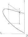
- FIG. 2 shows a diagram in which the enthalpy of a refrigerant is plotted on the abscissa and the ordinate logarithmically the pressure of this refrigerant, which occurs at the heat release condensation occurs.
- the numbers 1, 2, 3, 4a, 4b and 4c denote different states of the refrigerant (see. Fig. 1 ).
- the reference numeral 1 represents the state of the compressed, heated refrigerant, that is, the state of the refrigerant at the inlet 21 of the refrigerant / heating heat exchanger device 14.
- the refrigerant In the desuperheater 15, the refrigerant is isobarically cooled, which is the state 2 at the branching point 23 equivalent.
- the condenser 16 the refrigerant 15 is condensed and cooled further isobar.
- State 3 thus corresponds to the state of the refrigerant at the refrigerant outlet 22 of the refrigerant / heating heat exchanger device 14.
- Condition 2 refrigerant is depressurized via the second expansion element 26 to a state 4a.
- Refrigerant of state 3 is expanded via the third expansion element 29 to a state 4b.
- Refrigerant of the two states 4a, 4b mixes at the junction 30 to refrigerant of the state 4c.
- Refrigerant of the state 4c mixes with the coming of the evaporator 24 refrigerant to a state 4e in which it enters the collector 25.
- FIG. 3 shows the state points in the event that the refrigerant requires a supercritical cooling, as can be for example in the refrigerant carbon dioxide.
- the refrigerant in the first part of the refrigerant / heating heat exchanger means is cooled down to point 2 so far that when it expands to the point 4a either sufficient overheating is present or the point 4a lies at least to the right of the point 4c.
- the further cooling to point 3 takes place in the second part of the refrigerant / heating heat exchanger device on a supercritical isobar.
- the expansion elements 26, 29 are controlled in such a way that even at low ambient temperatures a sufficiently high heat output results with the highest possible overall efficiency.
- a first control strategy allows so much refrigerant through that the refrigerant compressor can condense with the highest possible rotational speed and thus also high power.
- FIG. 4 shows an embodiment in which instead of adjustable expansion elements 26, 29 non-controllable throttles or each orifice valve are provided.
- a shut-off valve 31 is arranged here between the junction 30 and the inlet 27 of the collector 25. Incidentally, the arrangement corresponds to the FIG. 3 the the FIG. 1 ,
- FIG. 5 shows an embodiment in which, unlike FIG. 1 the refrigerant path between the branch point 28 and the junction 30 is omitted. It is therefore not a third expansion element provided, but only the second expansion element 26.
- the state 4a of the refrigerant after the second expansion element 26 can be controlled here by controlling the heating circuit 17 by flowing liquid volume flow, ie by controlling the speed of the water pump 18.
- the expansion member 26 By controlling the expansion member 26, the mass flow of the additional refrigerant for the refrigerant compressor and thus the maximum possible speed of the compressor is controlled.
Landscapes
- Engineering & Computer Science (AREA)
- Physics & Mathematics (AREA)
- Thermal Sciences (AREA)
- Mechanical Engineering (AREA)
- General Engineering & Computer Science (AREA)
- Air-Conditioning For Vehicles (AREA)
- Compression-Type Refrigeration Machines With Reversible Cycles (AREA)
Description
Die vorliegende Erfindung betrifft ein Verfahren zum Betreiben eines Kältemittelkreislaufs als Wärmepumpe gemäß dem Oberbegriff des Patentanspruches 1 sowie einen als Wärmepumpe betreibbaren Kältemittelkreislauf gemäß dem Oberbegriff des Patentanspruches 17.The present invention relates to a method for operating a refrigerant circuit as a heat pump according to the preamble of claim 1 and a refrigerant circuit operable as a heat pump according to the preamble of
Ein Verfahren gemäß dem Oberbegriff des Patentanspruches 1 ist aus der
Bei Elektro- und Hybrid-Fahrzeugen werden zunehmend als Wärmepumpe betreibbare Kältemittelkreisläufe zur Temperierung des Fahrgastraumes und/oder einzelner Fahrzeugkomponenten in Betracht gezogen. Bei niedrigen Außentemperaturen (z.B. bei Temperaturen unter 0°C) erbringen Wärmepumpenkreisläufe mit den bei bisherigen Klimaanlagen üblichen Komponentengrößen, d.h. den üblichen Verdampfer- bzw. Kondensatorgrößen, nur eine vergleichsweise geringe Heizleistung, die unter dem Bedarf heutiger Fahrzeuge liegt. Bislang bekannte Wärmepumpenkonzepte für Fahrzeuge weisen daher in der Regel zusätzliche elektrische Heizeinrichtungen auf, die bei niedrigen Außentemperaturen eine elektrische "Zuheizung" ermöglichen.In electric and hybrid vehicles operable refrigerant circuits for temperature control of the passenger compartment and / or individual vehicle components are increasingly considered as a heat pump into consideration. At low outdoor temperatures (eg at temperatures below 0 ° C) provide heat pump cycles with the usual in previous air conditioning components sizes, ie the usual evaporator or condenser sizes, only a comparatively low heating power, which is below the needs of today's vehicles. As a rule, hitherto known heat pump concepts for vehicles therefore have additional electrical heating devices which enable electrical "additional heating" at low outside temperatures.
Aufgabe der Erfindung ist es, ein Verfahren zum Betreiben eines Kältemittelkreislaufs anzugeben, das auch bei niedrigen Außentemperaturen eine hinreichend hohe Heizleistung ermöglicht, sowie einen entsprechend geeigneten Kältemittelkreislauf zu schaffen.The object of the invention is to provide a method for operating a refrigerant circuit, which allows a sufficiently high heat output even at low outdoor temperatures, and to provide a correspondingly suitable refrigerant circuit.
Diese Aufgabe wird durch die Merkmale der Patentansprüche 1 bzw. 17 gelöst. Vorteilhafte Ausgestaltungen und Weiterbildungen der Erfindung sind den Unteransprüchen zu entnehmen.This object is solved by the features of
Ausgangspunkt der Erfindung ist die Idee, durch die Konzeption des Kältemittelkreislaufs und durch eine geeignete Betriebsstrategie sicherzustellen, dass (insbesondere bei niedrigen Außentemperaturen) der vom Kältemittelverdichter angesaugte und verdichtete Kältemittelmassenstrom bzw. die Dichte des vom Kältemittelverdichter geförderten Kältemittels möglichst hoch ist.The starting point of the invention is the idea to ensure by the design of the refrigerant circuit and by a suitable operating strategy that (in particular at low outside temperatures) the refrigerant mass flow drawn in and compressed by the refrigerant compressor or the density of the refrigerant conveyed by the refrigerant compressor is as high as possible.
Prinzipiell könnte in Betracht gezogen werden, den Kältemittelvolumenstrom über eine Drehzahlanpassung des Kältemittelverdichters zu regeln. Der Kältemittelmassenstrom hängt allerdings nicht nur vom Kältemittelvolumenstrom des Verdichters, sondern auch von der Dichte des Kältemittels am Eintritt des Kältemittelverdichters ab. Im Übrigen kann der Kältemittelstrom nicht beliebig gesteigert werden, da ansonsten die Temperatur am Verdampfer bzw. an den Verdampfern des Kältemittelkreislaufs zu stark absinken würde.In principle, it could be considered to regulate the refrigerant volume flow via a speed adjustment of the refrigerant compressor. However, the refrigerant mass flow depends not only on the refrigerant volume flow of the compressor, but also on the density of the refrigerant at the inlet of the refrigerant compressor. Incidentally, the refrigerant flow can not be increased arbitrarily, otherwise the temperature at the evaporator or at the evaporators of the refrigerant circuit would decrease too much.
Durch die vorliegende Erfindung lassen sich beide Probleme lösen.The present invention solves both problems.
Ein Kältemittelkreislauf gemäß der Erfindung weist einen Kältemittelverdichter auf, der Kältemittel ansaugt, verdichtet und durch eine "Kältemittel-/Heizungswärmetauschereinrichtung" oder zusätzlichen einen Kondensator/Gaskühler im Klimagerät pumpt. Die "Kältemittel-/Heizungswärmetauschereinrichtung" kann z.B. eine "Kältemittel-/Flüssigkeitswärmetauschereinrichtung" sein, über die Wärme von dem Kältemittel an eine in einem Heizkreis umgepumpte Flüssigkeit übertragen wird, oder eine "Kältemittel-/Luftwärmetauschereinrichtung", über die Wärme von dem Kältemittel (ohne einen zwischengeschalteten von Flüssigkeit durchströmten Heizkreislauf) an die in einen Fahrgastraum einströmende Luft übertragen wird.A refrigerant circuit according to the invention includes a refrigerant compressor that draws refrigerant, compresses, and pumps through a "refrigerant / heating heat exchange device" or additional a condenser / gas cooler in the air conditioner. For example, the "refrigerant / heating heat exchange device" may be a "refrigerant / liquid heat exchange device". be transmitted via the heat from the refrigerant to a liquid circulated in a heating circuit, or a "refrigerant / air heat exchange means", transfer the heat from the refrigerant (without an intermediate fluid flowed through the heating circuit) to the air flowing into a passenger compartment becomes.
Von der Kältemittel-/Heizungswärmetauschereinrichtung kommendes Kältemittel wird in mindestens einem ersten Expansionsorgan entspannt. Das entspannte Kältemittel durchströmt mindestens einen Verdampfer des Kältemittelkreislaufs und strömt von dort zurück in Richtung zu einem Saugeingang des Verdichters.Refrigerant coming from the refrigerant / heater core is depressurized in at least one first expansion device. The expanded refrigerant flows through at least one evaporator of the refrigerant circuit and flows from there back toward a suction inlet of the compressor.
Bei dem mindestens einen Verdampfer kann es sich beispielsweise um einen Umgebungswärmetauscher handeln, der Wärme aus der Umgebungsluft aufnimmt. Insbesondere können auch mehrere Verdampfer vorgesehen sein, z.B. ein Verdampfer, der eine Fahrzeugkomponente, wie z.B. einen Hochvoltspeicher o.ä., kühlt.The at least one evaporator can be, for example, an ambient heat exchanger that absorbs heat from the ambient air. In particular, a plurality of evaporators may also be provided, e.g. an evaporator comprising a vehicle component, e.g. a high-voltage storage or similar, cools.
Der Kern der Erfindung besteht darin, dass an einer zwischen einem Kältemitteleingang und einem Kältemittelausgang der Kältemittel-/Heizungswärmetauschereinrichtung befindlichen Abzweigstelle der Kältemittel-Heizungsswärmetauschereinrichtung Kältemittel abgezweigt und über ein zweites Expansionsorgan in Richtung zu dem Saugeingang geleitet wird. Die Kältemittel-/Heizungswärmetauschereinrichtung kann eine Kältemittel-/Flüssigkeitswärmetauschereinrichtung sein, die das Kältemittel abkühlt und eventuell auch kondensiert, wobei die übertragene Wärme zur Beheizung des Innenraums über einen Heizkreislauf mit einem Heizungswärmeübertrager im Klimagerät genutzt wird. Alternativ dazu kann die Kältemittel-/Heizungswärmetauschereinrichtung eine Kältemittel - Luftwärmetauschereinrichtung sein, die das Kältemittel abkühlt und eventuell auch kondensiert, wobei diese Wärme zur Beheizung des Innenraums direkt im Klimagerät genutzt wird. Je nach Kältemittel erfolgt in der Kältemittel-/Heizungswärmetauschereinrichtung nur eine Abkühlung des Kältemittels oder auch zusätzlich eine Kondensation.The gist of the invention is that refrigerant is branched off at a branch point of the refrigerant heat exchanger heat exchanger device located between a refrigerant inlet and a refrigerant outlet of the refrigerant / heating heat exchanger device and conducted via a second expansion device in the direction of the suction inlet. The refrigerant / Heizungswärmetauschereinrichtung may be a refrigerant / liquid heat exchanger means which cools the refrigerant and possibly also condenses, wherein the heat transferred to heat the interior via a heating circuit is used with a heating heat exchanger in the air conditioner. Alternatively, the refrigerant / heating heat exchanger device may be a refrigerant - air heat exchanger device which cools the refrigerant and possibly also condenses, this heat for heating the interior directly used in the air conditioner. Depending on the refrigerant takes place in the refrigerant / Heizungswärmetauschereinrichtung only a cooling of the refrigerant or in addition a condensation.
Dem von dem mindestens einen Verdampfer kommenden Kältemittelmassenstrom kann somit ein Kältemittelmassenstrom beigemischt werden, der von der Abzweigstelle der Kältemittel-/Heizungswärmetauschereinrichtung abgezweigt wird. Dadurch kann die Dichte des vom Kältemittelverdichter angesaugten Kältemittels bzw. der Kältemittelmassenstrom so eingestellt bzw. geregelt werden, dass sich auch bei niedrigen Außentemperaturen eine möglichst hohe Heizleistung ergibt.The refrigerant mass flow coming from the at least one evaporator can thus be admixed with a refrigerant mass flow which is branched off from the branch point of the refrigerant / heating heat exchanger device. As a result, the density of the refrigerant drawn in by the refrigerant compressor or the refrigerant mass flow can be adjusted or regulated in such a way that the highest possible heating power results even at low outside temperatures.
Nach einer Weiterbildung der Erfindung ist in dem Abschnitt des Kältemittelkreislaufs, der sich zwischen der Abzweigstelle der Kältemittel-/Heizungswärmetauschereinrichtung und dem Saugeingang des Kältemittelverdichters befindet, ein zweites Expansionsorgan vorgesehen.According to a development of the invention, a second expansion element is provided in the section of the refrigerant circuit which is located between the branch point of the refrigerant / heating heat exchanger device and the suction inlet of the refrigerant compressor.
Die Kältemittel-/Heizungswärmetauschereinrichtung kann gedanklich in einen "ersten Abschnitt" untergliedert werden, der sich vom Kältemitteleingang bis zur Abzweigstelle erstreckt. In diesem ersten Abschnitt wird das durch den Kältemittelverdichter verdichtete und erhitzte Kältemittel abgekühlt, wobei vorgesehen sein kann, dass es auf dem gesamten ersten Abschnitt gasförmig, d.h. überhitzt, bleibt. Dementsprechend könnte der erste Abschnitt der Kältemittel-/Heizungswärmetauschereinrichtung als "Enthitzer" bezeichnet werden, über den gasförmiges Kältemittel abgekühlt wird.The refrigerant / heating heat exchanger device may be conceptually divided into a "first section" extending from the refrigerant inlet to the branch point. In this first section, the refrigerant compressed and heated by the refrigerant compressor is cooled, and it may be provided that it is gaseous, i.e., gaseous, over the entire first section. overheated, remains. Accordingly, the first portion of the refrigerant / heater core may be referred to as a "desuperheater" through which gaseous refrigerant is cooled.
Ein "zweiter Abschnitt" der Kältemittel-/Heizungswärmetauschereinrichtung ist durch den zwischen der Abzweigstelle und dem Kältemittelausgang befindlichen Abschnitt gebildet. Auf diesem Abschnitt gibt das Kältemittel weiter Wärme ab und kondensiert je nach Kältemittel bzw. wird überkritisch weiter abgekühlt. Der zweite Abschnitt könnte als "Kondensator oder Gaskühler" bezeichnet werden, indem das vom ersten Abschnitt kommende, gasförmige Kältemittel ganz oder teilweise kondensiert bzw. überkritisch abgekühlt wird.A "second portion" of the refrigerant / heating heat exchange device is formed by the portion located between the branch point and the refrigerant outlet. In this section, the refrigerant continues to give off heat and condense depending on the refrigerant or is supercritically cooled further. The second section could be called "capacitor or Gas cooler "are designated by the coming of the first section, gaseous refrigerant is completely or partially condensed or cooled supercritically.
Nach einer Weiterbildung der Erfindung ist der Kältemittelkreislauf über die Kältemittel-/Heizungswärmetauschereinrichtung (in diesem Zusammenhang Kältemittel-/Flüssigkeitswärmetauschereinrichtung) thermisch mit einem von Flüssigkeit durchströmten Heizkreislauf gekoppelt. Bei der Kältemittel-/Flüssigkeitswärmetauschereinrichtung kann es sich um eine Wärmetauscher-Einrichtung handeln, die von Kältemittel und Flüssigkeit im Gegenstrom durchströmt ist (Gegenstromwärmetauscher). Der oben erwähnte Enthitzer-Abschnitt und der Kondensator- oder Gaskühler-Abschnitt können durch zwei Abschnitte eines einzigen Gegenstrom-Wärmetauschers gebildet sein. Alternativ dazu können der Enthitzer und der Kondensator bzw. Gaskühler auch durch zwei separate, in Reihe geschaltete Gegenstromwärmetauscher gebildet sein.According to a development of the invention, the refrigerant circuit is thermally coupled via the refrigerant / heating heat exchanger device (in this context refrigerant / liquid heat exchanger device) with a heating circuit through which liquid flows. The refrigerant / liquid heat exchanger device may be a heat exchanger device through which refrigerant and liquid flow in countercurrent (countercurrent heat exchanger). The above-mentioned desuperheater section and the condenser or gas cooler section may be formed by two sections of a single countercurrent heat exchanger. Alternatively, the desuperheater and the condenser or gas cooler may also be formed by two separate, countercurrent heat exchangers connected in series.
Der Heizkreislauf weist eine Kühlmittel- bzw. Wasserpumpe, die beiden Abschnitte (Enthitzer-Abschnitt und Kondensator- bzw. Gaskühler-Abschnitt) der Kältemittel-/Flüssigkeitswärmetauschereinrichtung und einen Heizungswärmetauscher auf. Bei dem Heizungswärmetauscher, der sich normalerweise im Klimagerät befindet, handelt es sich um einen Flüssigkeits-/Luftwärmetauscher, über den Wärme von der Flüssigkeit bzw. dem Wasser an die in einen Fahrgastraum eines Fahrzeugs einströmende Luft abgegeben werden kann.The heating circuit has a coolant or water pump, the two sections (desuperheater section and condenser or gas cooler section) of the refrigerant / liquid heat exchanger device and a heating heat exchanger. The heater core, normally located in the air conditioner, is a liquid / air heat exchanger through which heat from the liquid or water to the air flowing into a passenger compartment of a vehicle can be released.
Nach einer anderen Weiterbildung der Erfindung ist die Kältemittel-/Heizungswärmetauschereinrichtung als eine Kältemittel-/Luftwärmetauschereinrichtung ausgebildet. Der Kältemittelkreislauf gibt hier die Heizwärme über die Kältemittel-/Luftwärmetauschereinrichtung, die sich normalerweise im Klimagerät befindet, direkt an die in einen Fahrgastraum eines Fahrzeugs einströmende Luft ab. Hierbei können die beiden Teile der Kältemittel-/Luftwärmetauschereinrichtung luftseitig in Serie geschaltet sein, wobei vorzugsweise der erste Teil nach dem zweiten Teil luftseitig durchströmt wird.According to another embodiment of the invention, the refrigerant / Heizungswärmetauschereinrichtung is designed as a refrigerant / air heat exchange device. The refrigerant circuit is here, the heating heat through the refrigerant / air heat exchanger device, which is normally located in the air conditioner, directly to the in a passenger compartment of a vehicle incoming air from. Here, the two parts of the refrigerant / air heat exchanger means may be connected in series on the air side, wherein preferably the first part is flowed through on the air side of the second part.
Nach einer Weiterbildung der Erfindung ist nach dem Kältemittelausgang des Kältemittel-/Heizungswärmetauschereinrichtung, d.h. zwischen der Kältemittel-/Heizungswärmetauschereinrichtung und dem mindestens einen ersten Expansionsorgan eine weitere Abzweigstelle vorgesehen, welche über ein drittes Expansionsorgan mit dem Saugeingang des Kältemittelverdichters in Fluidverbindung steht.According to a development of the invention, after the refrigerant outlet of the refrigerant / heating heat exchanger device, i. a further branch point is provided between the refrigerant / heating heat exchanger device and the at least one first expansion element, which is in fluid communication with the suction inlet of the refrigerant compressor via a third expansion element.
Bei dem zweiten und/oder dem dritten Expansionsorgan kann es sich vorzugsweise um regelbare Expansionsorgane handeln. Alternativ dazu kann es sich auch um einfache Expansionsorgane mit festem Strömungsquerschnitt handeln, die jeweils geöffnet - oder geschlossen werden können.The second and / or the third expansion element may preferably be controllable expansion elements. Alternatively, it can also be simple expansion organs with a fixed flow cross-section, which can be opened or closed respectively.
Im Folgenden wird die Erfindung im Zusammenhang mit der Zeichnung näher erläutert. Es zeigen:
- Figur 1
- Ein erstes Ausführungsbeispiel eines Kältemittelkreislaufs gemäß der Erfindung;
Figur 2- ein vereinfachtes log(p)-h-Diagramm zur Erläuterung einzelner Zustandspunkte eines Kältemittels;
Figur 3- ein vereinfachtes log(p)-h-Diagramm zur Erläuterung einzelner Zustandspunkte eines Kältemittels mit überkritischer Betriebsweise;
- Figuren 4, 5
- weitere Ausführungsbeispiele eines Kältemittelkreislaufs gemäß der Erfindung.
- FIG. 1
- A first embodiment of a refrigerant circuit according to the invention;
- FIG. 2
- a simplified log (p) -h diagram for explaining individual state points of a refrigerant;
- FIG. 3
- a simplified log (p) -h diagram for explaining individual state points of a refrigerant with supercritical operation;
- FIGS. 4, 5
- Further embodiments of a refrigerant circuit according to the invention.
Bei dem hier gezeigten Ausführungsbeispiel ist die Kältemittel-/Flüssigkeitswärmetauschereinrichtung 14 durch zwei in Serie geschaltete Gegenstromwärmetauscher 15, 16 gebildet. Über die Kältemittel-/Flüssigkeitswärmetauschereinrichtung 14 ist der Kältemittelkreislauf 10 thermisch mit einem Heizkreislauf 17 gekoppelt. Der Heizkreislauf 17 weist eine Wasserpumpe 18 auf, welche Heizflüssigkeit bzw. Wasser entgegen der Strömungsrichtung des Kältemittels zunächst durch den Wärmetauscher 16 und dann durch den Wärmetauscher 15 und schließlich durch einen Heizwärmetauscher 19 pumpt. Über die Kühlmittel-Flüssigkeitswärmetauscher-Einrichtung 14 kann Wärme von dem durch den Kältemittelmittelverdichter 11 komprimierten Kältemittel an die im Heizkreislauf 17 umgepumpte Flüssigkeit abgegeben werden. Über den Heizwärmetauscher 19 kann Wärme aus der im Heizkreislauf 17 umgepumpten Flüssigkeit an eine in einen Fahrgastraum eines Fahrzeugs einzublasende Luft 20, welche den Heizwärmetauscher 19 durch- und/oder umströmt, abgegeben werden.In the embodiment shown here, the refrigerant / liquid
Der Wärmetauscher 15 fungiert als Enthitzer, der in Serie dazu geschaltete Wärmetauscher 16 fungiert als Kondensator bzw. bei einem Kältemittel in überkritischer Betriebsweise als Gaskühler. Kältemittel, welches durch den Kältemittelverdichter 11 verdichtet und erhitzt wurde, gibt zunächst über den Wärmetauscher 15 Wärme ab. Das Kältemittel verbleibt dabei im gasförmigen Zustand, kühlt sich jedoch ab. Im Wärmetauscher 16 wird das Kältemittel weiter abgekühlt und je nach Kältemittel dabei teilweise oder vollständig kondensiert bzw. überkritisch abgekühlt.The
Die Kühlmittel-Flüssigkeitswärmetauscher-Einrichtung 14 weist einen Kältemitteleingang 21, einen Kältemittelausgäng 22 und eine Abzweigstelle 23 auf. Die Abzweigstelle 23 befindet sich, in Strömungsrichtung des Kältemittels betrachtet, zwischen dem Kältemitteleingang 21 und dem Kältemittelausgang 22. Bei dem hier gezeigten Ausführungsbeispiel, bei dem die Kältemittel-/Flüssigkeitswärmetauschereinrichtung 14 durch zwei separate Wärmetauscher 15, 16 gebildet ist, befindet sich die Abzweigstelle 23 zwischen den beiden Wärmetauschern 15, 16.The coolant / liquid
Alternativ zu dem hier gezeigten Ausführungsbeispiel können der "Enthitzer-Abschnitt 15" und der "Kondensator-Abschnitt 16" auch in einem einzigen Wärmetauscher zusammengefasst sein. In diesem Fall befände sich die Abzweigstelle 23 in dem Wärmetauscher.As an alternative to the exemplary embodiment shown here, the "
Vom Kältemittelausgang 22 kommendes Kältemittel strömt zu einem ersten Expansionsorgan 23', das hier als elektrisch bzw. elektronisch steuerbares bzw. regelbares Expansionsorgan ausgebildet wird. Im Expansionsorgan 23' wird das Kältemittel entspannt, wodurch es sich abkühlt. Das entspannte Kältemittel durchströmt anschließend einen Verdampfer bzw. Umgebungswärmetauscher 24. Anstatt eines einzigen Verdampfers können auch mehrere Verdampfer vorgesehen und z.B. parallel geschaltet sein. Im Verdampfer 24 nimmt das Kältemittel Wärme auf, z.B. aus der Umgebungsluft oder aus einer zu kühlenden Fahrzeugkomponente. Nach Durchströmen des Verdampfers 24 strömt das Kältemittel über einen Sammler 25 zurück zum Saugeingang 12 des Verdichters 11.Coming from the
Wie aus
Eine zwischen dem Ausgang 22 und dem ersten Expansionsorgan 23' vorgesehene Abzweigstelle 28 steht über ein drittes Expansionsorgan 29, das hier ebenfalls als steuerbares bzw. regelbares Expansionsorgan ausgebildet ist, in Strömungsverbindung mit dem Eingang 27 des Sammlers 25.A branching
Am Sammlereingang 27 kann ein Temperatursensor und/oder ein Drucksensor (nicht dargestellt) vorgesehen sein. Eine hier nicht näher dargestellte Elektronik regelt die steuerbaren Expansionsorgane 26, 29 so, dass am Eingang 27 des Sammlers 25 keine oder nur eine geringe Überhitzung des Kältemittels auftritt, wodurch erreicht wird, dass die Dichte des vom Kältemittelverdichter 11 geförderten Kältemittels vergleichsweise hoch und dementsprechend auch der vom Kältemittelverdichter 11 geförderte Kältemittelmassenstrom hoch ist. Dadurch kann auch bei niedrigen Außentemperaturen, d.h. bei Außentemperaturen, bei denen über einen Umgebungswärmetauscher bzw. Verdampfer 24 nur vergleichsweise geringe Wärmeleistung aufgenommen wird, eine hinreichend hohe, zur Beheizung eines Fahrzeugs ausreichende Wärmeleistung erzeugt werden. Insbesondere ist dadurch auch eine höhere Drehzahl des Verdichters möglich.At the
Kältemittel des Zustands 2 wird über das zweite Expansionsorgan 26 auf einen Zustand 4a entspannt. Kältemittel des Zustands 3 wird über das dritte Expansionsorgan 29 auf einen Zustand 4b entspannt. Kältemittel der beiden Zustände 4a, 4b vermischt sich an der Vereinigungsstelle 30 zu Kältemittel des Zustands 4c. Kältemittel des Zustands 4c vermischt sich mit dem vom Verdampfer 24 kommenden Kältemittel zu einem Zustand 4e, in dem es in den Sammler 25 eintritt.
Wie bereits erwähnt, werden die Expansionsorgane 26, 29 so gesteuert, dass sich auch bei niedrigen Umgebungstemperaturen eine ausreichend hohe Heizleistung bei einem möglichst hohen Gesamtwirkungsgrad ergibt.As already mentioned, the
Eine erste Regelstrategie lässt durch Öffnen des Ventils 26 so viel Kältemittel durch, dass der Kältemittelverdichter mit einer möglichst hohen Drehzahl und damit auch hoher Leistung verdichten kann.By opening the
Bei einer zweiten Regelstrategie wird durch Öffnen des Ventils 29 so viel Kältemittel des Zustands 4b zugemischt, dass das vom Kältemittelverdichter angesaugte Kältemittel einen Zustand 4e mit möglichst hoher Dichte aufweist. Somit wird durch beide Strategien ein Maximum an Heizleistung bei eine festgelegten maximalen Leistung der einzelnen Verdampfer generiert.In a second control strategy, opening the
Claims (23)
- A method for operating a refrigerant circuit (10) as a heat pump, whereinð refrigerant is compressed and is pumped through a heat-exchanger device (14) by means of a compressor,ð refrigerant coming from the heat-exchanger device (14) is expanded in at least one first expansion member (23'),ð refrigerant which has been expanded by means of the first expansion member (23') flows through at least one evaporator (24) to a suction input (12) of the compressor (11),wherein refrigerant is branched off at a branch-off point (23) of the heat-exchanger device (14) located between a refrigerant input (21) and a refrigerant output (22) of the heat-exchanger device (14) and is conducted via a second expansion member(26), and bypassing- a portion (16) of the heat-exchanger device (14) which is located downstream from the refrigerant branch-off (23), and- the at least one first expansion member (23'), and- the at least one evaporator (24),in the direction of the suction input (12),
characterised in thatð the heat-exchanger device (14) is a refrigerant/heating heat-exchanger device,ð with heat emitted from the refrigerant via the refrigerant/heating heat-exchanger device (14) being utilised to heat a passenger compartment of a vehicle. - A method according to Claim 1,
characterised in that the refrigerant is cooled between the refrigerant input (21) and the branch-off point (23). - A method according to Claim 2,
characterised in that the refrigerant is cooled further between the branch-off point (23) and the refrigerant output (22), so that it condenses. - A method according to one of Claims 1 to 3,
characterised in that the refrigerant is cooled further supercritically between the branch-off point (23) and the refrigerant output (22). - A method according to one of Claims 1 to 4,
characterised in that the refrigerant circuit (10) is thermally coupled by means of the refrigerant/heating heat-exchanger device (14) with a heating circuit (17) through which liquid flows, the refrigerant/heating heat-exchanger device (14) being a refrigerant/liquid heat-exchanger device (14). - A method according to Claim 5,
characterised in that the heating circuit (17) has a liquid pump (18), the delivery rate of which is adjustable. - A method according to one of Claims 1 to 4,
characterised in that the refrigerant/heating heat-exchanger device (14) is a refrigerant/air heat-exchanger device which emits the heat directly to an air flow which is to be heated. - A method according to Claim 7, characterised in that the two parts of the refrigerant/air heat-exchanger device are connected in series on the air side, with preferably the flow passing through the first part after the second part on the air side.
- A method according to one of Claims 1 to 8,
characterised in that refrigerant is branched off after the refrigerant output (22) of the refrigerant/heating heat-excha nger device (14) and is conducted via a third expansion member (29) in the direction of the suction input (11). - A method according to one of Claims 1 to 9,
characterised in that refrigerant coming from the at least one evaporator (24) is conducted to the suction input (12) via a collector (25). - A method according to Claim 10,
characterised in that refrigerant coming from the second expansion member (26) flows via the collector (25) to the suction input (12). - A method according to one of the preceding claims,
characterised in that refrigerant coming from the third expansion member (29) flows via the collector (25) to the suction input (12). - A method according to one of the preceding claims,
characterised in that the density of the refrigerant at the suction input (12) of the compressor (11) and/orthe refrigerant mass flow at the suction input (12) is regulated by controlling- the second expansion member (26) and/or- the third expansion member (29) and/or- the speed of the compressor (11). - A method according to one of Claims 7 to 13,
characterised in that at or before a refrigerant input(27) of the collector(25)- the pressure of the refrigerant is measured by means of a pressure sensor, and/or- the temperature of the refrigerant is measured by means of a temperature sensor and the density of the refrigerant is ascertained therefrom. - A method according to Claim 14,
characterised in that the second and/or the third expansion member (26, 29) is controlled or regulated as a function of the pressure and/or the temperature of the refrigerant. - A method according to one of the preceding claims,
characterised in that the density of the refrigerant at the entrance to the expansion member (26) is regulated by the speed of the water pump (18). - A refrigerant circuit which can be operated as a heat pump, having- a compressor (11),- a heat-exchanger device (14) arranged in the direction of flow of the refrigerant after the compressor,- which device has a refrigerant input (21) which is in fluidic connection with the pressure side (13) of the compressor (11) and- a refrigerant output (22);- at least a first expansion member (23') which is in a flow connection with the refrigerant output (22),- at least one evaporator (24) arranged in the direction of flow of the refrigerant after the first expansion member, from which evaporator refrigerant flows to a suction input (12) of the compressor (11),- wherein the heat-exchanger device (14) at a point located between the refrigerant input (21) and the refrigerant output (22) has a refrigerant branch-off (23) via which refrigerant flows via a second expansion member(26), and bypassing- a portion (16) of the heat-exchanger device (14) located downstream from the refrigerant branch-off (23), and- the at least one first expansion member (23'), and- the at least one evaporator (24) to the suction side (12) of the compressor,characterised in thatð the heat-exchanger device (14) is a refrigerant/liquid heat-exchanger device (14), withð the refrigerant circuit being thermally coupled via the refrigerant/liquid heat-exchanger device (14) to a heating circuit (17) through which liquid flows.
- A refrigerant circuit according to Claim 17,
characterised in that a collector(25) is provided which is arranged between the at least one evaporator (24) and the suction input (12) or between the refrigerant branch-off (23) and the suction input (12). - A refrigerant circuit according to Claim 18,
characterised in that a second expansion member (26) is arranged between the refrigerant branch-off (23) and the collector (25). - A refrigerant circuit according to one of Claims 18 or 19,
characterised in that the refrigerant output (22) of the refrigerant/liquid heat-exchanger device (14) is connected to the collector (25) via a third expansion member (29). - A refrigerant circuit according to Claim 20,
characterised in that the second and/or the third expansion member (26, 29) is a expansion memberwhich can be regulated. - A refrigerant circuit according to Claim 20,
characterised in that the second and/or the third expansion member (26, 29) is a throttle with a fixed flow cross-section. - A refrigerant circuit according to one of Claims 17 to 22,
characterised in that the heating circuit (17) has a pump (18), the delivery rate of which is adjustable.
Applications Claiming Priority (2)
| Application Number | Priority Date | Filing Date | Title |
|---|---|---|---|
| DE102012222594.3A DE102012222594B4 (en) | 2012-12-10 | 2012-12-10 | Method for operating a refrigerant circuit as a heat pump and as a heat pump operable refrigerant circuit |
| PCT/EP2013/073201 WO2014090484A1 (en) | 2012-12-10 | 2013-11-07 | Method for operating a refrigerant circuit as a heat pump and heat pump operable as a refrigerant circuit |
Publications (2)
| Publication Number | Publication Date |
|---|---|
| EP2928710A1 EP2928710A1 (en) | 2015-10-14 |
| EP2928710B1 true EP2928710B1 (en) | 2018-08-08 |
Family
ID=49546418
Family Applications (1)
| Application Number | Title | Priority Date | Filing Date |
|---|---|---|---|
| EP13786499.7A Active EP2928710B1 (en) | 2012-12-10 | 2013-11-07 | Method for operating a refrigerant circuit as a heat pump |
Country Status (5)
| Country | Link |
|---|---|
| US (1) | US9625188B2 (en) |
| EP (1) | EP2928710B1 (en) |
| CN (1) | CN104661841B (en) |
| DE (1) | DE102012222594B4 (en) |
| WO (1) | WO2014090484A1 (en) |
Families Citing this family (10)
| Publication number | Priority date | Publication date | Assignee | Title |
|---|---|---|---|---|
| US10272744B2 (en) * | 2015-09-03 | 2019-04-30 | Ford Global Technologies, Llc | Vehicle HVAC system with auxiliary coolant loop for heating and cooling vehicle interior |
| CN106322828B (en) * | 2016-04-17 | 2020-05-01 | 李华玉 | Second-class thermally-driven compression heat pump |
| DE102016213619A1 (en) | 2016-07-25 | 2018-01-25 | Bayerische Motoren Werke Aktiengesellschaft | METHOD FOR OPERATING A CLIMATE SYSTEM AND CLIMATE SYSTEM |
| FR3055249B1 (en) * | 2016-08-30 | 2018-09-14 | Valeo Systemes Thermiques | INDIRECT INDIRECT AIR CONDITIONING CIRCUIT FOR A MOTOR VEHICLE AND METHOD OF OPERATING THE SAME |
| EP3617616B1 (en) * | 2017-04-27 | 2023-11-15 | Mitsubishi Electric Corporation | Refrigeration cycle device |
| KR20190120936A (en) * | 2018-04-17 | 2019-10-25 | 한온시스템 주식회사 | Heat management system of vehicle |
| DE102018214211A1 (en) * | 2018-08-22 | 2020-02-27 | Volkswagen Aktiengesellschaft | Device and method for tempering an electrical energy store for a motor vehicle |
| DE102019120229A1 (en) | 2019-07-26 | 2021-01-28 | Bayerische Motoren Werke Aktiengesellschaft | Thermal management system for a motor vehicle, method for thermal management of a motor vehicle and motor vehicle with a thermal management system |
| DE102020117701A1 (en) | 2020-07-06 | 2022-01-13 | Audi Aktiengesellschaft | Refrigeration system with a heat pump function based on an expandable base system and motor vehicle with such a refrigeration system |
| DE102020128840B4 (en) | 2020-11-03 | 2023-08-31 | Bayerische Motoren Werke Aktiengesellschaft | Air conditioning system, method for controlling such and motor vehicle |
Family Cites Families (14)
| Publication number | Priority date | Publication date | Assignee | Title |
|---|---|---|---|---|
| US4163369A (en) * | 1978-05-11 | 1979-08-07 | Charles Owen | Air-to-air heat pump |
| US4474018A (en) * | 1982-05-06 | 1984-10-02 | Arthur D. Little, Inc. | Heat pump system for production of domestic hot water |
| JP3794121B2 (en) * | 1997-02-28 | 2006-07-05 | 株式会社デンソー | Air conditioner for vehicles |
| EP1148307B1 (en) * | 2000-04-19 | 2004-03-17 | Denso Corporation | Heat-pump water heater |
| US6293108B1 (en) * | 2000-06-30 | 2001-09-25 | Vortex Aircon | Regenerative refrigeration system with mixed refrigerants |
| US6536221B2 (en) * | 2001-01-16 | 2003-03-25 | Norbert L. James | Air conditioning heat recovery arrangement |
| DE10207128A1 (en) * | 2002-02-20 | 2003-08-21 | Zexel Valeo Compressor Europe | Vehicle air conditioning system, especially carbon dioxide unit, has additional heat exchanger and pressure reducing throttle valve |
| JP2004182204A (en) * | 2002-12-06 | 2004-07-02 | Mitsubishi Heavy Ind Ltd | Air conditioner for vehicle and air conditioning method for vehicle |
| BRPI0508190B1 (en) * | 2004-02-26 | 2019-12-24 | Ventech Llc | heating appliance and heating system |
| DE102007034821A1 (en) | 2007-07-26 | 2009-01-29 | Ford Global Technologies, LLC, Dearborn | Air conditioning system for a motor vehicle and method for its operation |
| CN100535550C (en) * | 2008-07-29 | 2009-09-02 | 广州精益汽车空调有限公司 | Automobile heat pump air conditioner system |
| WO2011052031A1 (en) * | 2009-10-27 | 2011-05-05 | 三菱電機株式会社 | Heat pump |
| JP5423528B2 (en) * | 2010-03-29 | 2014-02-19 | 株式会社日本自動車部品総合研究所 | Heat pump cycle |
| JP2012132586A (en) * | 2010-12-20 | 2012-07-12 | Calsonic Kansei Corp | Refrigeration cycle device |
-
2012
- 2012-12-10 DE DE102012222594.3A patent/DE102012222594B4/en not_active Expired - Fee Related
-
2013
- 2013-11-07 CN CN201380050178.0A patent/CN104661841B/en active Active
- 2013-11-07 EP EP13786499.7A patent/EP2928710B1/en active Active
- 2013-11-07 WO PCT/EP2013/073201 patent/WO2014090484A1/en active Application Filing
-
2015
- 2015-06-09 US US14/734,535 patent/US9625188B2/en active Active
Non-Patent Citations (1)
| Title |
|---|
| None * |
Also Published As
| Publication number | Publication date |
|---|---|
| WO2014090484A1 (en) | 2014-06-19 |
| US20150276281A1 (en) | 2015-10-01 |
| EP2928710A1 (en) | 2015-10-14 |
| DE102012222594B4 (en) | 2018-05-17 |
| US9625188B2 (en) | 2017-04-18 |
| DE102012222594A1 (en) | 2014-06-12 |
| CN104661841A (en) | 2015-05-27 |
| CN104661841B (en) | 2017-08-04 |
Similar Documents
| Publication | Publication Date | Title |
|---|---|---|
| EP2928710B1 (en) | Method for operating a refrigerant circuit as a heat pump | |
| EP3444542B1 (en) | Circulation system for a vehicle and method for same | |
| EP3697635B1 (en) | Method for operating a coolant circuit and vehicle air-conditioning system | |
| EP1264715B2 (en) | Vehicle cooling system for a temperature increasing device as well as method for the cooling of the temperature increasing device | |
| DE102012111672B4 (en) | Refrigerant circuit of an air conditioning system with heat pump and reheat functionality | |
| EP1526974B1 (en) | Air conditioner for a motor vehicle | |
| DE102015122721B4 (en) | Air conditioning system of a motor vehicle and method for operating the air conditioning system | |
| DE102014115530B4 (en) | Method for regulating the coolant temperature of a HVAC heat pump system field | |
| DE102010051976B4 (en) | Air conditioning for a motor vehicle | |
| DE102020111505B4 (en) | Heat pump arrangement for battery-operated vehicles and method for operating a heat pump arrangement | |
| DE112013003304T5 (en) | Vehicle air conditioning unit | |
| DE102014112343A1 (en) | Vehicle air conditioning system with a switching heat exchanger | |
| DE102012108731A1 (en) | Air conditioning for a motor vehicle | |
| DE102013206626A1 (en) | Heat pump system and method for air conditioning a vehicle | |
| DE102020117471B4 (en) | Heat pump arrangement with indirect battery heating for battery-operated motor vehicles and method for operating a heat pump arrangement | |
| WO2014166596A1 (en) | Vehicle climate control device | |
| WO2012159814A1 (en) | Heat pump circuit for vehicles | |
| WO2019214927A1 (en) | Cooling system for a vehicle having a refrigerant circuit comprising a heat pump function | |
| EP1462281B1 (en) | Air conditiong device with multiple evaporators for a motor vehicle | |
| DE112015000750T5 (en) | Refrigerant fluid circuit for thermal treatment of a motor vehicle | |
| DE102013219146A1 (en) | Vehicle heat pump system and control method | |
| WO2014154326A1 (en) | Vehicle air-conditioning device | |
| DE102017124811A1 (en) | An air conditioning system for conditioning the air of a passenger compartment of a motor vehicle and method for operating the air conditioning system | |
| DE102017213973A1 (en) | Method for operating a refrigeration system of a vehicle having a refrigerant circuit having a cooling and heating function | |
| WO2023280507A1 (en) | Refrigeration circuit, and heat management system and motor vehicle having a refrigeration circuit of this type |
Legal Events
| Date | Code | Title | Description |
|---|---|---|---|
| PUAI | Public reference made under article 153(3) epc to a published international application that has entered the european phase |
Free format text: ORIGINAL CODE: 0009012 |
|
| 17P | Request for examination filed |
Effective date: 20150429 |
|
| AK | Designated contracting states |
Kind code of ref document: A1 Designated state(s): AL AT BE BG CH CY CZ DE DK EE ES FI FR GB GR HR HU IE IS IT LI LT LU LV MC MK MT NL NO PL PT RO RS SE SI SK SM TR |
|
| AX | Request for extension of the european patent |
Extension state: BA ME |
|
| DAX | Request for extension of the european patent (deleted) | ||
| 17Q | First examination report despatched |
Effective date: 20171220 |
|
| GRAP | Despatch of communication of intention to grant a patent |
Free format text: ORIGINAL CODE: EPIDOSNIGR1 |
|
| RIC1 | Information provided on ipc code assigned before grant |
Ipc: F25B 30/02 20060101ALI20180305BHEP Ipc: B60H 1/00 20060101AFI20180305BHEP |
|
| INTG | Intention to grant announced |
Effective date: 20180321 |
|
| GRAS | Grant fee paid |
Free format text: ORIGINAL CODE: EPIDOSNIGR3 |
|
| GRAA | (expected) grant |
Free format text: ORIGINAL CODE: 0009210 |
|
| AK | Designated contracting states |
Kind code of ref document: B1 Designated state(s): AL AT BE BG CH CY CZ DE DK EE ES FI FR GB GR HR HU IE IS IT LI LT LU LV MC MK MT NL NO PL PT RO RS SE SI SK SM TR |
|
| REG | Reference to a national code |
Ref country code: GB Ref legal event code: FG4D Free format text: NOT ENGLISH |
|
| REG | Reference to a national code |
Ref country code: CH Ref legal event code: EP Ref country code: AT Ref legal event code: REF Ref document number: 1026576 Country of ref document: AT Kind code of ref document: T Effective date: 20180815 |
|
| REG | Reference to a national code |
Ref country code: IE Ref legal event code: FG4D Free format text: LANGUAGE OF EP DOCUMENT: GERMAN |
|
| REG | Reference to a national code |
Ref country code: DE Ref legal event code: R096 Ref document number: 502013010816 Country of ref document: DE |
|
| REG | Reference to a national code |
Ref country code: NL Ref legal event code: MP Effective date: 20180808 |
|
| REG | Reference to a national code |
Ref country code: LT Ref legal event code: MG4D |
|
| PG25 | Lapsed in a contracting state [announced via postgrant information from national office to epo] |
Ref country code: RS Free format text: LAPSE BECAUSE OF FAILURE TO SUBMIT A TRANSLATION OF THE DESCRIPTION OR TO PAY THE FEE WITHIN THE PRESCRIBED TIME-LIMIT Effective date: 20180808 Ref country code: IS Free format text: LAPSE BECAUSE OF FAILURE TO SUBMIT A TRANSLATION OF THE DESCRIPTION OR TO PAY THE FEE WITHIN THE PRESCRIBED TIME-LIMIT Effective date: 20181208 Ref country code: LT Free format text: LAPSE BECAUSE OF FAILURE TO SUBMIT A TRANSLATION OF THE DESCRIPTION OR TO PAY THE FEE WITHIN THE PRESCRIBED TIME-LIMIT Effective date: 20180808 Ref country code: PL Free format text: LAPSE BECAUSE OF FAILURE TO SUBMIT A TRANSLATION OF THE DESCRIPTION OR TO PAY THE FEE WITHIN THE PRESCRIBED TIME-LIMIT Effective date: 20180808 Ref country code: NL Free format text: LAPSE BECAUSE OF FAILURE TO SUBMIT A TRANSLATION OF THE DESCRIPTION OR TO PAY THE FEE WITHIN THE PRESCRIBED TIME-LIMIT Effective date: 20180808 Ref country code: GR Free format text: LAPSE BECAUSE OF FAILURE TO SUBMIT A TRANSLATION OF THE DESCRIPTION OR TO PAY THE FEE WITHIN THE PRESCRIBED TIME-LIMIT Effective date: 20181109 Ref country code: NO Free format text: LAPSE BECAUSE OF FAILURE TO SUBMIT A TRANSLATION OF THE DESCRIPTION OR TO PAY THE FEE WITHIN THE PRESCRIBED TIME-LIMIT Effective date: 20181108 Ref country code: BG Free format text: LAPSE BECAUSE OF FAILURE TO SUBMIT A TRANSLATION OF THE DESCRIPTION OR TO PAY THE FEE WITHIN THE PRESCRIBED TIME-LIMIT Effective date: 20181108 Ref country code: FI Free format text: LAPSE BECAUSE OF FAILURE TO SUBMIT A TRANSLATION OF THE DESCRIPTION OR TO PAY THE FEE WITHIN THE PRESCRIBED TIME-LIMIT Effective date: 20180808 Ref country code: SE Free format text: LAPSE BECAUSE OF FAILURE TO SUBMIT A TRANSLATION OF THE DESCRIPTION OR TO PAY THE FEE WITHIN THE PRESCRIBED TIME-LIMIT Effective date: 20180808 |
|
| PG25 | Lapsed in a contracting state [announced via postgrant information from national office to epo] |
Ref country code: LV Free format text: LAPSE BECAUSE OF FAILURE TO SUBMIT A TRANSLATION OF THE DESCRIPTION OR TO PAY THE FEE WITHIN THE PRESCRIBED TIME-LIMIT Effective date: 20180808 Ref country code: AL Free format text: LAPSE BECAUSE OF FAILURE TO SUBMIT A TRANSLATION OF THE DESCRIPTION OR TO PAY THE FEE WITHIN THE PRESCRIBED TIME-LIMIT Effective date: 20180808 Ref country code: HR Free format text: LAPSE BECAUSE OF FAILURE TO SUBMIT A TRANSLATION OF THE DESCRIPTION OR TO PAY THE FEE WITHIN THE PRESCRIBED TIME-LIMIT Effective date: 20180808 |
|
| PG25 | Lapsed in a contracting state [announced via postgrant information from national office to epo] |
Ref country code: EE Free format text: LAPSE BECAUSE OF FAILURE TO SUBMIT A TRANSLATION OF THE DESCRIPTION OR TO PAY THE FEE WITHIN THE PRESCRIBED TIME-LIMIT Effective date: 20180808 Ref country code: ES Free format text: LAPSE BECAUSE OF FAILURE TO SUBMIT A TRANSLATION OF THE DESCRIPTION OR TO PAY THE FEE WITHIN THE PRESCRIBED TIME-LIMIT Effective date: 20180808 Ref country code: CZ Free format text: LAPSE BECAUSE OF FAILURE TO SUBMIT A TRANSLATION OF THE DESCRIPTION OR TO PAY THE FEE WITHIN THE PRESCRIBED TIME-LIMIT Effective date: 20180808 Ref country code: RO Free format text: LAPSE BECAUSE OF FAILURE TO SUBMIT A TRANSLATION OF THE DESCRIPTION OR TO PAY THE FEE WITHIN THE PRESCRIBED TIME-LIMIT Effective date: 20180808 |
|
| REG | Reference to a national code |
Ref country code: DE Ref legal event code: R097 Ref document number: 502013010816 Country of ref document: DE |
|
| PG25 | Lapsed in a contracting state [announced via postgrant information from national office to epo] |
Ref country code: SM Free format text: LAPSE BECAUSE OF FAILURE TO SUBMIT A TRANSLATION OF THE DESCRIPTION OR TO PAY THE FEE WITHIN THE PRESCRIBED TIME-LIMIT Effective date: 20180808 Ref country code: DK Free format text: LAPSE BECAUSE OF FAILURE TO SUBMIT A TRANSLATION OF THE DESCRIPTION OR TO PAY THE FEE WITHIN THE PRESCRIBED TIME-LIMIT Effective date: 20180808 Ref country code: SK Free format text: LAPSE BECAUSE OF FAILURE TO SUBMIT A TRANSLATION OF THE DESCRIPTION OR TO PAY THE FEE WITHIN THE PRESCRIBED TIME-LIMIT Effective date: 20180808 |
|
| PLBE | No opposition filed within time limit |
Free format text: ORIGINAL CODE: 0009261 |
|
| STAA | Information on the status of an ep patent application or granted ep patent |
Free format text: STATUS: NO OPPOSITION FILED WITHIN TIME LIMIT |
|
| REG | Reference to a national code |
Ref country code: CH Ref legal event code: PL |
|
| 26N | No opposition filed |
Effective date: 20190509 |
|
| PG25 | Lapsed in a contracting state [announced via postgrant information from national office to epo] |
Ref country code: LU Free format text: LAPSE BECAUSE OF NON-PAYMENT OF DUE FEES Effective date: 20181107 Ref country code: MC Free format text: LAPSE BECAUSE OF FAILURE TO SUBMIT A TRANSLATION OF THE DESCRIPTION OR TO PAY THE FEE WITHIN THE PRESCRIBED TIME-LIMIT Effective date: 20180808 |
|
| REG | Reference to a national code |
Ref country code: BE Ref legal event code: MM Effective date: 20181130 |
|
| REG | Reference to a national code |
Ref country code: IE Ref legal event code: MM4A |
|
| PG25 | Lapsed in a contracting state [announced via postgrant information from national office to epo] |
Ref country code: LI Free format text: LAPSE BECAUSE OF NON-PAYMENT OF DUE FEES Effective date: 20181130 Ref country code: SI Free format text: LAPSE BECAUSE OF FAILURE TO SUBMIT A TRANSLATION OF THE DESCRIPTION OR TO PAY THE FEE WITHIN THE PRESCRIBED TIME-LIMIT Effective date: 20180808 Ref country code: CH Free format text: LAPSE BECAUSE OF NON-PAYMENT OF DUE FEES Effective date: 20181130 |
|
| PG25 | Lapsed in a contracting state [announced via postgrant information from national office to epo] |
Ref country code: IE Free format text: LAPSE BECAUSE OF NON-PAYMENT OF DUE FEES Effective date: 20181107 |
|
| PG25 | Lapsed in a contracting state [announced via postgrant information from national office to epo] |
Ref country code: BE Free format text: LAPSE BECAUSE OF NON-PAYMENT OF DUE FEES Effective date: 20181130 |
|
| REG | Reference to a national code |
Ref country code: AT Ref legal event code: MM01 Ref document number: 1026576 Country of ref document: AT Kind code of ref document: T Effective date: 20181107 |
|
| PG25 | Lapsed in a contracting state [announced via postgrant information from national office to epo] |
Ref country code: AT Free format text: LAPSE BECAUSE OF NON-PAYMENT OF DUE FEES Effective date: 20181107 Ref country code: MT Free format text: LAPSE BECAUSE OF FAILURE TO SUBMIT A TRANSLATION OF THE DESCRIPTION OR TO PAY THE FEE WITHIN THE PRESCRIBED TIME-LIMIT Effective date: 20180808 |
|
| PG25 | Lapsed in a contracting state [announced via postgrant information from national office to epo] |
Ref country code: TR Free format text: LAPSE BECAUSE OF FAILURE TO SUBMIT A TRANSLATION OF THE DESCRIPTION OR TO PAY THE FEE WITHIN THE PRESCRIBED TIME-LIMIT Effective date: 20180808 |
|
| PG25 | Lapsed in a contracting state [announced via postgrant information from national office to epo] |
Ref country code: PT Free format text: LAPSE BECAUSE OF FAILURE TO SUBMIT A TRANSLATION OF THE DESCRIPTION OR TO PAY THE FEE WITHIN THE PRESCRIBED TIME-LIMIT Effective date: 20180808 |
|
| PG25 | Lapsed in a contracting state [announced via postgrant information from national office to epo] |
Ref country code: CY Free format text: LAPSE BECAUSE OF FAILURE TO SUBMIT A TRANSLATION OF THE DESCRIPTION OR TO PAY THE FEE WITHIN THE PRESCRIBED TIME-LIMIT Effective date: 20180808 Ref country code: MK Free format text: LAPSE BECAUSE OF NON-PAYMENT OF DUE FEES Effective date: 20180808 Ref country code: HU Free format text: LAPSE BECAUSE OF FAILURE TO SUBMIT A TRANSLATION OF THE DESCRIPTION OR TO PAY THE FEE WITHIN THE PRESCRIBED TIME-LIMIT; INVALID AB INITIO Effective date: 20131107 |
|
| P01 | Opt-out of the competence of the unified patent court (upc) registered |
Effective date: 20230502 |
|
| PGFP | Annual fee paid to national office [announced via postgrant information from national office to epo] |
Ref country code: GB Payment date: 20231123 Year of fee payment: 11 |
|
| PGFP | Annual fee paid to national office [announced via postgrant information from national office to epo] |
Ref country code: IT Payment date: 20231130 Year of fee payment: 11 Ref country code: FR Payment date: 20231122 Year of fee payment: 11 Ref country code: DE Payment date: 20231113 Year of fee payment: 11 |