WO2011052031A1 - Heat pump - Google Patents
Heat pump Download PDFInfo
- Publication number
- WO2011052031A1 WO2011052031A1 PCT/JP2009/068358 JP2009068358W WO2011052031A1 WO 2011052031 A1 WO2011052031 A1 WO 2011052031A1 JP 2009068358 W JP2009068358 W JP 2009068358W WO 2011052031 A1 WO2011052031 A1 WO 2011052031A1
- Authority
- WO
- WIPO (PCT)
- Prior art keywords
- refrigerant
- heat
- radiator
- heat pump
- heat exchanger
- Prior art date
Links
Images


Classifications
-
- F—MECHANICAL ENGINEERING; LIGHTING; HEATING; WEAPONS; BLASTING
- F25—REFRIGERATION OR COOLING; COMBINED HEATING AND REFRIGERATION SYSTEMS; HEAT PUMP SYSTEMS; MANUFACTURE OR STORAGE OF ICE; LIQUEFACTION SOLIDIFICATION OF GASES
- F25B—REFRIGERATION MACHINES, PLANTS OR SYSTEMS; COMBINED HEATING AND REFRIGERATION SYSTEMS; HEAT PUMP SYSTEMS
- F25B30/00—Heat pumps
- F25B30/02—Heat pumps of the compression type
-
- F—MECHANICAL ENGINEERING; LIGHTING; HEATING; WEAPONS; BLASTING
- F25—REFRIGERATION OR COOLING; COMBINED HEATING AND REFRIGERATION SYSTEMS; HEAT PUMP SYSTEMS; MANUFACTURE OR STORAGE OF ICE; LIQUEFACTION SOLIDIFICATION OF GASES
- F25B—REFRIGERATION MACHINES, PLANTS OR SYSTEMS; COMBINED HEATING AND REFRIGERATION SYSTEMS; HEAT PUMP SYSTEMS
- F25B13/00—Compression machines, plants or systems, with reversible cycle
-
- F—MECHANICAL ENGINEERING; LIGHTING; HEATING; WEAPONS; BLASTING
- F25—REFRIGERATION OR COOLING; COMBINED HEATING AND REFRIGERATION SYSTEMS; HEAT PUMP SYSTEMS; MANUFACTURE OR STORAGE OF ICE; LIQUEFACTION SOLIDIFICATION OF GASES
- F25B—REFRIGERATION MACHINES, PLANTS OR SYSTEMS; COMBINED HEATING AND REFRIGERATION SYSTEMS; HEAT PUMP SYSTEMS
- F25B6/00—Compression machines, plants or systems, with several condenser circuits
- F25B6/04—Compression machines, plants or systems, with several condenser circuits arranged in series
-
- F—MECHANICAL ENGINEERING; LIGHTING; HEATING; WEAPONS; BLASTING
- F25—REFRIGERATION OR COOLING; COMBINED HEATING AND REFRIGERATION SYSTEMS; HEAT PUMP SYSTEMS; MANUFACTURE OR STORAGE OF ICE; LIQUEFACTION SOLIDIFICATION OF GASES
- F25B—REFRIGERATION MACHINES, PLANTS OR SYSTEMS; COMBINED HEATING AND REFRIGERATION SYSTEMS; HEAT PUMP SYSTEMS
- F25B2313/00—Compression machines, plants or systems with reversible cycle not otherwise provided for
- F25B2313/023—Compression machines, plants or systems with reversible cycle not otherwise provided for using multiple indoor units
- F25B2313/0233—Compression machines, plants or systems with reversible cycle not otherwise provided for using multiple indoor units in parallel arrangements
-
- F—MECHANICAL ENGINEERING; LIGHTING; HEATING; WEAPONS; BLASTING
- F25—REFRIGERATION OR COOLING; COMBINED HEATING AND REFRIGERATION SYSTEMS; HEAT PUMP SYSTEMS; MANUFACTURE OR STORAGE OF ICE; LIQUEFACTION SOLIDIFICATION OF GASES
- F25B—REFRIGERATION MACHINES, PLANTS OR SYSTEMS; COMBINED HEATING AND REFRIGERATION SYSTEMS; HEAT PUMP SYSTEMS
- F25B2339/00—Details of evaporators; Details of condensers
- F25B2339/04—Details of condensers
- F25B2339/047—Water-cooled condensers
-
- F—MECHANICAL ENGINEERING; LIGHTING; HEATING; WEAPONS; BLASTING
- F25—REFRIGERATION OR COOLING; COMBINED HEATING AND REFRIGERATION SYSTEMS; HEAT PUMP SYSTEMS; MANUFACTURE OR STORAGE OF ICE; LIQUEFACTION SOLIDIFICATION OF GASES
- F25B—REFRIGERATION MACHINES, PLANTS OR SYSTEMS; COMBINED HEATING AND REFRIGERATION SYSTEMS; HEAT PUMP SYSTEMS
- F25B2400/00—General features or devices for refrigeration machines, plants or systems, combined heating and refrigeration systems or heat-pump systems, i.e. not limited to a particular subgroup of F25B
- F25B2400/05—Compression system with heat exchange between particular parts of the system
-
- F—MECHANICAL ENGINEERING; LIGHTING; HEATING; WEAPONS; BLASTING
- F25—REFRIGERATION OR COOLING; COMBINED HEATING AND REFRIGERATION SYSTEMS; HEAT PUMP SYSTEMS; MANUFACTURE OR STORAGE OF ICE; LIQUEFACTION SOLIDIFICATION OF GASES
- F25B—REFRIGERATION MACHINES, PLANTS OR SYSTEMS; COMBINED HEATING AND REFRIGERATION SYSTEMS; HEAT PUMP SYSTEMS
- F25B25/00—Machines, plants or systems, using a combination of modes of operation covered by two or more of the groups F25B1/00 - F25B23/00
- F25B25/005—Machines, plants or systems, using a combination of modes of operation covered by two or more of the groups F25B1/00 - F25B23/00 using primary and secondary systems
-
- F—MECHANICAL ENGINEERING; LIGHTING; HEATING; WEAPONS; BLASTING
- F25—REFRIGERATION OR COOLING; COMBINED HEATING AND REFRIGERATION SYSTEMS; HEAT PUMP SYSTEMS; MANUFACTURE OR STORAGE OF ICE; LIQUEFACTION SOLIDIFICATION OF GASES
- F25B—REFRIGERATION MACHINES, PLANTS OR SYSTEMS; COMBINED HEATING AND REFRIGERATION SYSTEMS; HEAT PUMP SYSTEMS
- F25B7/00—Compression machines, plants or systems, with cascade operation, i.e. with two or more circuits, the heat from the condenser of one circuit being absorbed by the evaporator of the next circuit
Definitions
- the present invention relates to a heat pump including a compressor, a plurality of radiators, an expansion valve, and an evaporator.
- Patent Document 1 discloses a primary refrigerant circuit in which a compressor, a plurality of gas coolers, an expansion valve, and an evaporator are connected by refrigerant piping, and a secondary refrigerant circuit in which the gas cooler and a circulation pump are connected by piping.
- a heat pump provided with the above has been proposed.
- water flowing through the secondary refrigerant circuit is heated by a gas cooler, and this heated water is used for hot water supply, air conditioning, floor heating, and the like.
- the connection method (series connection or parallel connection) of the gas cooler according to the inflow temperature of the water which flows in into a gas cooler is proposed.
- the COP is improved by arranging the gas cooler by a connection method according to the inflow temperature of the water flowing into the gas cooler, and using the heat energy of the refrigerant flowing through the gas cooler in cascade.
- Patent Document 2 proposes a heat pump that performs refrigeration and freezing by connecting a high-source side refrigeration system that assists heat dissipation of the low-source side refrigeration system to the radiator outlet of the low-source side refrigeration system.
- this heat pump cools the refrigerant at the outlet of the outdoor heat exchanger using a high-side refrigeration system to improve the refrigerating capacity.
- JP 2004-003801 A pages 16 to 20, FIGS. 4 to 8
- JP 2008-002759 A (7th to 9th pages, FIG. 1)
- the present invention has been made to solve the above-described problems, and operates with a high COP even when the inflow temperature of a heated medium used for heating, hot water supply or the like flowing into the radiator increases. It aims to provide a heat pump that can be used.
- a first compressor, a plurality of radiators, a first pressure reducing device, and an evaporator are connected by a refrigerant pipe to form a first refrigeration cycle circuit.
- the plurality of radiators are connected in series, and when viewed along the flow direction of the first refrigerant, at least one of the second and subsequent radiators includes a radiator.
- the first heat exchange part for heating the first refrigerant is provided in the refrigerant pipe on the refrigerant inlet side, and the heat dissipated in the most upstream part among the radiators provided with the first heat exchange part.
- the radiator or the radiator on the downstream side of the radiator is provided with a second heat exchange part for cooling the first refrigerant in the refrigerant pipe on the refrigerant outlet side.
- At least one of the second and subsequent radiators is provided with a first heat exchange unit that heats the first refrigerant in the refrigerant pipe on the refrigerant inlet side of the radiator. .
- a first heat exchange unit that heats the first refrigerant in the refrigerant pipe on the refrigerant inlet side of the radiator.
- coolant which flows through an evaporator can be enlarged. Therefore, the heat collecting ability in the evaporator is improved, and the efficiency (heating ability) of the heat pump is improved. Therefore, it is possible to obtain a heat pump that can be operated with a high COP even when the temperature of a medium to be heated used for heating, hot water supply or the like flowing into the radiator increases.
- FIG. 3 is a refrigerant circuit diagram illustrating an example of a heat pump according to Embodiment 1.
- FIG. 3 is a refrigerant circuit diagram illustrating another example of the heat pump according to Embodiment 1.
- FIG. 6 is a refrigerant circuit diagram illustrating still another example of the heat pump according to Embodiment 1.
- FIG. 6 is a refrigerant circuit diagram illustrating an example of a heat pump according to Embodiment 2.
- FIG. FIG. 6 is a Ph diagram of a primary refrigerant when a secondary refrigeration cycle circuit is not operated in the heat pump according to the second embodiment.
- FIG. 10 is a Ph diagram of the primary refrigerant when the secondary refrigeration cycle is operated in the heat pump according to the second embodiment.
- FIG. 6 is a refrigerant circuit diagram illustrating an example of a heat pump according to Embodiment 3.
- FIG. 6 is a refrigerant circuit diagram illustrating the flow of refrigerant and water during cooling operation in the heat pump according to Embodiment 3.
- 10 is a Ph diagram during cooling operation in the heat pump according to Embodiment 3.
- FIG. 9 is a refrigerant circuit diagram illustrating the flow of refrigerant and water during heating operation in the heat pump according to Embodiment 3.
- FIG. 10 is a Ph diagram during heating operation in the heat pump according to the third embodiment.
- FIG. 6 is a refrigerant circuit diagram illustrating the flow of refrigerant and water during cooling main operation in the heat pump according to Embodiment 3.
- FIG. 10 is a Ph diagram during cooling main operation in the heat pump according to the third embodiment.
- FIG. 6 is a refrigerant circuit diagram illustrating the flow of refrigerant and water during heating-main operation in the heat pump according to Embodiment 3.
- FIG. 10 is a Ph diagram during heating-main operation in the heat pump according to the third embodiment. It is a figure which shows the flow of the refrigerant
- FIG. FIG. 10 is a Ph diagram when the secondary cycle is operated in the heating operation mode of the heat pump according to the third embodiment.
- FIG. 6 is a refrigerant circuit diagram illustrating another example of a heat pump according to Embodiment 3.
- FIG. 6 is a refrigerant circuit diagram illustrating still another example of a heat pump according to Embodiment 3.
- FIG. 6 is a refrigerant circuit diagram illustrating still another example of a heat pump according to Embodiment 3.
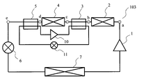
- FIG. 1 is a refrigerant circuit diagram illustrating an example of a heat pump according to Embodiment 1.
- the heat pump refers to a refrigeration apparatus that performs hot water supply and air conditioning.
- a first compressor 1, a first radiator 2, a second radiator 4, an expansion valve 6 and an evaporator 7 are connected by a refrigerant pipe to form a primary refrigeration cycle circuit.
- the heat pump 100 is used for heating, for example, and the air (first radiator 2 and second radiator 4) supplied by a fan or the like (not shown) is used as the first radiator 2. And it heats with the primary side refrigerant
- a refrigerant for example, carbon dioxide
- the expansion valve 6 corresponds to the first decompression device of the present invention
- the primary side refrigeration cycle circuit corresponds to the first refrigeration cycle circuit of the present invention
- the primary refrigerant corresponds to the first refrigerant of the present invention.
- the first pressure reducing device is not limited to the expansion valve 6, and various devices can be used. For example, a capillary or the like may be used as the first decompression device.
- the first heat exchange unit 3 is provided in the upstream pipe of the second radiator 4. This 1st heat exchange part 3 heats the primary side refrigerant
- FIG. 1 illustrates an example using two radiators (first radiator 2 and second radiator 4), a plurality (two or more) radiators may be connected in series. If it is.
- the 1st heat exchange part 3 should just be provided in the at least 1 upstream piping (refrigerant inlet side piping) of the 2nd or more radiators along the flow direction of the primary side refrigerant.
- the second radiator 4 is a radiator disposed in the most upstream portion of the radiators provided with the first heat exchanging section 3 or a downstream pipe of a radiator downstream of the radiator. What is necessary is just to provide in (refrigerant exit side piping).
- the second heat exchanging unit 5 is provided in the downstream pipe of the radiator disposed in the most downstream part, but for example, when the interval between the radiators is separated, the second heat exchange unit 5 has flowed out of the intermediate radiator. This is because the primary refrigerant may need to be cooled by the second heat exchange unit 5.
- the plurality of radiators are not limited to air heat exchangers that exchange heat with air, but are water, brine, etc. (hereinafter simply referred to as water when there is no need to distinguish between water, brine, etc.) and heat. You may use the water heat exchanger to replace
- both the air heat exchanger and the water heat exchanger may be provided in the primary side refrigeration cycle circuit.
- FIG. 2 is a refrigerant circuit diagram illustrating another example of the heat pump according to the first embodiment.
- Water is supplied in series to the first radiator 2 and the second radiator 4 via the pump 8.
- coolant and the flow direction of water are counterflow.
- the water heated by the first radiator 2 and the second radiator 4 is used for hot water supply, for example. Further, for example, water heated by the first radiator 2 and the second radiator 4 flows into indoor units, panel heaters, radiators, and the like connected to the water circuit, and is used for heating and floor heating.
- first radiator 2 and the second radiator 4 water heat exchanger
- a plate type water heat exchanger As the first radiator 2 and the second radiator 4 (water heat exchanger), a plate type water heat exchanger, a double pipe type water heat exchanger, and a water heat exchanger such as a microchannel type are used. Should be used.
- FIG. 3 is a refrigerant circuit diagram illustrating still another example of the heat pump according to the first embodiment.
- the first radiator 2 and the second radiator 4 are separately supplied with water used for water supply and heating. More specifically, water is supplied to the first radiator 2 via the pump 9. Water is supplied to the second radiator 4 via a pump 8. Thus, water may be supplied to the first radiator 2 and the second radiator 4 in series.
- the first compressor 1 sucks the refrigerant evaporated by the evaporator 7 through an accumulator (not shown). During normal operation, the first compressor 1 compresses the primary refrigerant to a critical pressure or higher. An accumulator may not be provided.
- the primary refrigerant compressed by the first compressor 1 flows into the first radiator 2 and is supplied (inflowed) by air or water supplied by a fan (not shown) or a pump (pumps 8 and 9). It is cooled by exchanging heat with it.
- the primary side refrigerant cooled by the first radiator 2 flows into the first heat exchange unit 3 and is heated by exchanging heat with a fluid having a temperature higher than that of the primary side refrigerant.
- the primary-side refrigerant heated in the first heat exchange unit 3 flows into the second radiator 4 and is cooled by exchanging heat with air or water supplied by a fan or a pump (pump 8).
- the primary side refrigerant cooled by the first radiator 2 flows into the first heat exchange unit 3 and is heated by exchanging heat with a fluid having a temperature higher than that of the primary side refrigerant.
- the primary side refrigerant heated in the first heat exchange unit 3 flows into the second heat exchange unit 5 and is cooled by exchanging heat with a fluid having a temperature lower than that of the primary side refrigerant.
- the refrigerant that has flowed out of the second heat exchange unit 5 is decompressed by the expansion valve 6 and becomes a low-temperature and low-pressure gas-liquid two-phase refrigerant.
- coolant flows in into the evaporator 7, and heat-exchanges with the air and water which flow into an evaporator (it absorbs heat from air and water).
- the primary refrigerant flowing out of the evaporator 7 is sucked into the compressor through an accumulator (not shown).
- the primary refrigerant cooled by the first radiator 2 is heated by the first heat exchange unit 3 and flows into the second radiator 4. .
- the temperature difference between the heated medium flowing into the second radiator 4 and the primary refrigerant. Can be increased.
- the heat exchange efficiency in the 2nd heat radiator 4 improves.
- the temperature of the primary-side refrigerant before flowing into the expansion valve 6 is lowered (for example, the second radiator).
- a refrigerant for example, carbon dioxide
- a refrigerant that operates in a supercritical state in the heat release process is used as the primary refrigerant.
- a refrigerant that operates at a critical pressure or lower in the heat dissipation process is used for a heat pump in which a radiator is connected in series
- the refrigerant flowing into the radiator may be in a gas-liquid two-phase state.
- it is necessary to consider the ratio of the gas-phase refrigerant to the liquid-phase refrigerant for example, it is necessary to provide a distributor or the like). is there).
- the refrigerant for example, carbon dioxide
- a refrigerant for example, carbon dioxide
- the refrigerant to each path (flow path) of the radiator. There is no need to consider distribution. For this reason, the flow rate of the refrigerant flowing through the radiator can be increased, and heat exchange can be performed efficiently.
- the heat exchanger used for a thermal radiation process may be called a condenser.
- the heat exchanger used in the heat dissipation process is referred to as a “heat radiator”.
- FIG. 2 the heat pump according to the present invention may be configured as follows.
- items that are not particularly described are the same as those in the first embodiment, and the same functions and configurations are described using the same reference numerals.
- FIG. 4 is a refrigerant circuit diagram illustrating an example of a heat pump according to the second embodiment.
- the primary side refrigeration cycle circuit of the heat pump 103 according to the second embodiment has the same configuration as the primary side refrigeration cycle circuit of the heat pump 100 shown in FIG. 1 of the first embodiment. However, it differs from the heat pump 100 shown in FIG. 1 of Embodiment 1 in that a secondary refrigeration cycle circuit including the first heat exchange unit 3 and the second heat exchange unit 5 as constituent elements is provided. .
- the heat pump 103 is a secondary-side refrigeration cycle circuit in which the second compressor 10, the first heat exchange unit 3, the second expansion valve 11, and the second heat exchange unit 5 are connected by a refrigerant circuit. It has.
- the secondary side refrigerant circulates in the secondary side refrigeration cycle circuit. That is, the same refrigerant flows through the first heat exchange unit 3 and the second heat exchange unit 5.
- the 1st heat exchange part 3 functions as a heat radiator
- the 2nd heat exchange part 5 functions as an evaporator.
- coolant in order to improve the heat exchange efficiency of a primary side refrigerant
- coolant in order to improve the heat exchange efficiency of a primary side refrigerant
- coolant in order to improve the heat exchange efficiency of a primary side refrigerant
- coolant in order to improve the heat exchange efficiency of a primary side refrigerant
- coolant in order to improve the heat exchange efficiency of a primary side refrigerant
- coolant in order to improve the heat exchange efficiency of a primary side refrigerant
- coolant in order to improve the heat exchange efficiency of a primary side refrigerant
- coolant in order to improve the heat exchange efficiency
- carbon dioxide refrigerant is used as the primary side refrigerant.
- propane refrigerant, HFO-1234yf refrigerant, ammonia refrigerant, or the like is used as the secondary refrigerant.
- These refrigerants have a higher theoretical COP at a vaporization temperature of 10 ° C. to 30 ° C. and a pseudocritical temperature or a condensation temperature of 30 ° C. to 50 ° C. than a carbon dioxide refrigerant.
- the primary side refrigerant and the secondary side refrigerant used in the heat pump 103 are refrigerants having a low GWP as compared to a refrigerant (GWP is about 2000) such as the R410A refrigerant normally used in the conventional heat pump.
- GWP global warming potential
- IPCC Intergovernmental Panel on Climate Change
- the second expansion valve 11 corresponds to the second decompression device of the present invention
- the secondary side refrigeration cycle circuit corresponds to the second refrigeration cycle circuit of the present invention
- the secondary refrigerant corresponds to the second refrigerant of the present invention.
- the second decompression device is not limited to the second expansion valve 11, and various devices can be used. For example, a capillary or the like may be used as the second decompression device.
- the 1st heat exchange part 3 should just be provided in the at least 1 upstream piping (refrigerant inlet side piping) of the 2nd or more radiators along the flow direction of the primary side refrigerant.
- the 2nd heat exchange part 5 is just to provide the 2nd heat exchange part 5 in the downstream piping (refrigerant outlet side piping) of the heat radiator arrange
- the plurality of radiators are not limited to air heat exchangers that exchange heat with air, and water heat exchangers may be used.
- air heat exchanger and water heat exchanger may be provided in the primary side refrigeration cycle circuit.
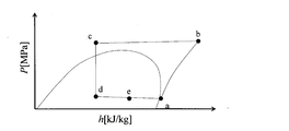
- FIG. 5 is a Ph diagram of the primary refrigerant when the secondary refrigeration cycle circuit is not operated in the heat pump according to the second embodiment.
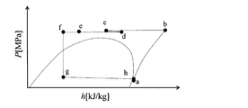
- FIG. 6 is a Ph diagram of the primary refrigerant when the secondary refrigeration cycle is operated in the heat pump according to the second embodiment. Note that a to e shown in FIGS. 5 and 6 are refrigerant states at the positions a to e shown in FIG. 5 and 6 show a case where the temperature T of the heated medium flowing into the second radiator 4 is T1 [° C.].
- the primary refrigerant flowing out of the first radiator 2 flows into the second radiator 4 without being heated (b ⁇ c). For this reason, when the temperature of the heated medium flowing into the second radiator 4 becomes high, the temperature difference between the heated medium flowing into the second radiator 4 and the primary refrigerant becomes small. Moreover, in order to heat a to-be-heated medium with the 2nd heat radiator 4, it is necessary to make the temperature of the primary side refrigerant
- the secondary side refrigeration cycle circuit when the secondary side refrigeration cycle circuit is operated as shown in FIG. 6, the primary side refrigerant flowing out of the first radiator 2 is heated by the first heat exchanger and then the second radiator. 4 (b ⁇ c). For this reason, even when the temperature of the heated medium flowing into the second radiator 4 increases, the temperature difference between the heated medium flowing into the second radiator 4 and the primary refrigerant can be increased. .
- the primary refrigerant that has flowed out of the second radiator 4 is cooled by the second heat exchange unit 5 and then flows into the expansion valve 6 (d ⁇ e). For this reason, the temperature of the primary side refrigerant
- the second heat exchange unit 5 collects the primary refrigerant from the primary refrigerant.
- the heat that has been used can be used to heat the primary refrigerant in the first heat exchange section 3. For this reason, the heating efficiency of the heat pump 103 is further improved.
- the temperature of the heated medium flowing into the radiator is 35 ° C.
- the primary refrigerant is carbon dioxide
- the secondary refrigerant is propane refrigerant
- the outlet of the second heat exchange unit 5 The heat pump 103 is operated so as to lower the temperature of the primary refrigerant at about 15 ° C. to 25 ° C.
- the heat exchanger is designed so that the logarithmic average temperature difference at the time of heat exchange between the carbon dioxide refrigerant and the propane refrigerant in each heat exchanger of the first heat exchange unit 3 and the second heat exchange unit 5 is about 5 ° C.
- the COP of the secondary side refrigerant that heats the carbon dioxide refrigerant is about 10 (including a loss due to the efficiency of the propane compressor), and a large heating capacity can be obtained with a small amount of electric input.
- the heating capacity (system COP) with respect to the sum of the electric inputs of the primary side refrigeration cycle circuit and the secondary side refrigeration cycle circuit is increased by 10 to 20% compared to the case where the secondary side cycle circuit is not operated.
- the heat pump 103 configured as described above, by operating the secondary side refrigeration cycle circuit when the temperature of the heated medium flowing into the radiator (particularly the second radiator 4) becomes high, In addition to the effects of the first embodiment, the heat collected from the primary refrigerant in the second heat exchange unit 5 can be used for heating the primary refrigerant in the first heat exchange unit 3. For this reason, the heating efficiency of the heat pump 103 is further improved.
- the secondary cycle circuit has a small number of parts and a small capacity, so the secondary side
- the amount of refrigerant necessary as the refrigerant is overwhelmingly smaller than the amount of refrigerant necessary for the primary side refrigerant.
- a reduction in the use of CFC-based refrigerant and high-efficiency operation leads to a reduction in greenhouse gas emissions.
- a refrigerant having a low GWP for both the primary side refrigerant and the secondary side refrigerant it is possible to further reduce greenhouse gas emissions due to refrigerant leakage and the like.
- Embodiment 3 For example, you may use the heat pump which concerns on this invention for the following air conditioning apparatuses.
- items that are not particularly described are the same as those in Embodiment 1 or Embodiment 2, and the same functions and configurations are described using the same reference numerals.
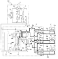
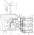
- FIG. 7 is a refrigerant circuit diagram illustrating an example of a heat pump according to the third embodiment.
- the heat pump 104 according to the third embodiment is installed away from each other by connecting the heat source unit A (outdoor unit), the relay unit B, and the plurality of indoor units (indoor units C, D, E) by piping.
- It is a multi-chamber air conditioner that can
- the heat source unit A can be installed on the roof of the building
- the relay unit B can be installed on the ceiling behind each floor of the building
- the indoor units C, D, and E can be installed in each room.
- the heat pump 104 is an air conditioner that can set cooling or heating for each indoor unit.
- the heat pump 104 performs heat transport from the heat source machine A to the relay machine B and heat transport from the relay machine B to the indoor units C, D, E using different refrigerant circuits.
- the heat transport to B is performed by a refrigerant such as carbon dioxide in which the pressure discharged from the compressor 21 is higher than the critical pressure.
- Heat transport from the relay unit B to the indoor units C, D, E is performed by water.
- brine such as antifreeze, a mixture of antifreeze and water, or a mixture of water and an additive having a high anticorrosion effect may be used.
- Embodiment 3 demonstrates the case where 1 relay machine and 3 indoor units are connected with respect to 1 heat source machine, 2 or more heat source machines, 2 or more relay machines, 2 or more The same applies when the indoor unit is connected.
- the heat source machine A includes a compressor 21, a four-way switching valve 22 for switching the flow direction of the refrigerant discharged from the compressor 21, a heat source side heat exchanger 23 (outdoor heat exchanger), an accumulator 24, and check valves 35 to 38, a flow path switching valve and the like are provided.
- a heat source side heat exchanger 23 outdoor heat exchanger
- accumulator 24 check valves 35 to 38, a flow path switching valve and the like
- a flow path switching valve and the like are provided.
- an air-cooled heat source side heat exchanger will be described as an example of the heat source side heat exchanger 23.
- other methods such as a water cooling type may be used as long as the refrigerant exchanges heat with other fluids. .
- the compressor 21 has a four-way switching valve 22 connected to the discharge side and an accumulator 24 connected to the suction side.
- the four-way switching valve 22 is connected to the compressor 21, the heat source side heat exchanger 23, the accumulator 24, and the flow path switching valve.
- the four-way switching valve 22 causes the refrigerant discharged from the compressor 21 to flow into the heat source side heat exchanger 23 (that is, the flow path from which the refrigerant flowing out of the flow switching valve flows into the accumulator 24), and compression.
- the flow path in which the refrigerant discharged from the machine 21 flows into the flow path switching valve (the flow path in which the refrigerant flown out from the heat source side heat exchanger 23 flows into the accumulator 24) is switched.
- the flow path switching valve includes four check valves (check valves 35 to 38).
- the check valve 35 is provided between the heat source side heat exchanger 23 and the second connection pipe 27 and allows the refrigerant to flow only from the heat source side heat exchanger 23 to the second connection pipe 27.
- the check valve 36 is provided between the four-way switching valve 22 of the heat source device A and the first connection pipe 26, and allows the refrigerant to flow only from the first connection pipe 26 to the four-way switching valve 22.
- the check valve 37 is provided between the four-way switching valve 22 of the heat source apparatus A and the second connection pipe 27, and allows the refrigerant to flow only from the four-way switching valve 22 to the second connection pipe 27.
- the check valve 38 is provided between the heat source side heat exchanger 23 and the first connection pipe 26, and allows the refrigerant to flow only from the first connection pipe 26 to the heat source side heat exchanger 23.
- the other end of the second connection pipe 27 is connected to a bypass pipe 39a of the repeater B described later.
- the other end of the first connection pipe 26 is connected to a first branch 30 of the repeater B described later.
- the refrigerant discharged from the compressor 21 always flows into the relay machine B through the second connection pipe 27, and the refrigerant flowing out of the relay machine B always has the first connection pipe 26. Will pass.
- the pipe diameter of the second connection pipe 27 can be made smaller than the pipe diameter of the first connection pipe 26.
- the indoor unit C includes an indoor heat exchanger 25c.
- One end of the indoor heat exchanger 25c is connected to flow path switching valves 42i and 42l of the relay machine B described later via a first connection pipe 26c.
- the other end of the indoor heat exchanger 25c is connected to flow path switching valves 42c and 42f of the relay machine B described later via a second connection pipe 27c.
- a flow rate control device 43c is provided in the second connection pipe 27c between the indoor heat exchanger 25c and the flow path switching valves 42c and 42f.
- the flow control device 43c may be provided in the first connection pipe 26c between the indoor heat exchanger 25c and the flow path switching valves 42i and 42l.
- the indoor unit D includes an indoor heat exchanger 25d.
- One end of the indoor heat exchanger 25d is connected to flow path switching valves 42j and 42m of the relay machine B described later via a first connection pipe 26d.
- the other end of the indoor heat exchanger 25d is connected to flow path switching valves 42d and 42g of the relay unit B described later via a second connection pipe 27d.
- a flow rate control device 43c is provided in the second connection pipe 27d between the indoor heat exchanger 25c and the flow path switching valves 42d and 42g.
- the flow control device 43c may be provided in the first connection pipe 26d between the indoor heat exchanger 25d and the flow path switching valves 42j and 42m.
- the indoor unit E includes an indoor heat exchanger 25e.
- One end of the indoor heat exchanger 25e is connected to flow path switching valves 42k and 42n of the relay machine B described later via a first connection pipe 26e.
- the other end of the indoor heat exchanger 25e is connected to flow path switching valves 42e and 42h of the relay machine B described later via a second connection pipe 27e.
- a flow rate control device 43c is provided in the second connection pipe 27e between the indoor heat exchanger 25e and the flow path switching valves 42e and 42h.
- the flow control device 43c may be provided in the first connection pipe 26e between the indoor heat exchanger 25e and the flow path switching valves 42k and 42n.
- the first connection pipes 26 c, 26 d, and 26 e are indoor unit side pipes corresponding to the first connection pipe 26. Further, the second connection pipes 27 c, 27 d, and 27 e are indoor unit side pipes corresponding to the second connection pipe 27.
- the first connection pipes 26c, 26d, and 26e and the second connection pipes 27c, 27d, and 27e are pipes through which water flows. Since the density of water flowing through the first connection pipes 26c, 26d, and 26e and the density of water flowing through the second connection pipes 27c, 27d, and 27e are substantially the same, the pipe diameters of these pipes may be the same.
- the relay B includes an intermediate heat exchanger 40 (intermediate heat exchangers 40a and 40b), first flow control devices 29a and 29b, a first branch unit 30, a second branch unit 31, and a second flow control device. 32, the 3rd flow control device 33 grade, etc. have the primary side refrigeration cycle circuit connected by piping.
- the relay machine B includes a secondary refrigeration cycle circuit in which the second compressor 50, the first heat exchange unit 51, the expansion valve 52, and the second heat exchange unit 53 are connected by piping.
- the first branch portion 30 includes electromagnetic valves 28a, 28b, 28c, and 28d.
- One end of each of the solenoid valves 28a and 28c is connected to the intermediate heat exchanger 40a.
- the other end of the electromagnetic valve 28 a is connected to the second connection pipe 27.
- the other end of the electromagnetic valve 28 c is connected to the first connection pipe 26.
- One end of each of the electromagnetic valves 28b and 28d is connected to the intermediate heat exchanger 40b.
- the 1st heat exchange part 51 is provided in piping which connects the solenoid valve 28b and the intermediate
- the other end of the electromagnetic valve 28 b is connected to the second connection pipe 27.
- the other end of the electromagnetic valve 28 d is connected to the first connection pipe 26.
- the second branch part 31 is connected to the intermediate heat exchangers 40a and 40b.
- a first flow rate control device 29a is provided between the second branch portion 31 and the intermediate heat exchanger 40a.
- the 1st flow control apparatus 29b and the 2nd heat exchange part 53 are provided from the 2nd branch part 31 side.
- the opening degree of the first flow control device 29a is adjusted by the degree of superheat on the outlet side of the intermediate heat exchanger 40a during cooling, and the degree of supercooling of the intermediate heat exchanger 40a during heating.
- the opening degree of the first flow control device 29b is adjusted by the degree of superheat on the outlet side of the intermediate heat exchanger 40b during cooling, and the degree of supercooling of the intermediate heat exchanger 40b during heating. Further, an electromagnetic valve 28e is provided so that the intermediate heat exchanger 40b is connected downstream of the intermediate heat exchanger a during the heating operation.
- the second branch portion 31 is connected to the second connection pipe 27 via the first bypass pipe 39a, and is connected to the first connection pipe 26 via the second bypass pipe 39b.
- the first bypass pipe 39a is provided with a second flow rate control device 32 that can be opened and closed
- the second bypass pipe 39b is provided with a third flow rate control device 33 that is adjustable in opening.
- the first bypass pipe 39a and the second bypass pipe 39b include an internal heat exchanger 34 that exchanges heat between the refrigerant flowing through the first bypass pipe 39a and the refrigerant flowing through the second bypass pipe 39b. Is provided.
- the internal heat exchanger 34 may not be provided.
- the second compressor 50, the first heat exchange unit 51, the expansion valve 52, and the second heat exchange unit 53 are connected by piping to form a secondary refrigeration cycle circuit.
- the intermediate heat exchangers 40a and 40b exchange heat between the primary refrigerant and water that transports heat to the indoor units C, D, and E.
- the intermediate heat exchangers 40a and 40b may be a plate type water heat exchanger, a double pipe type water heat exchanger, a water heat exchanger such as a microchannel type, or the like.
- the intermediate heat exchanger 40a is provided in the middle of a circuit for water in which water that performs heat transport to the indoor units C, D, and E circulates.
- One end of the water circuit is connected to the flow path switching valves 42c, 42d, and 42e.
- the other end of the water circuit is connected to the flow path switching valves 42i, 42j, and 42k.
- the water circuit is provided with a pump 41a for circulating water in the water circuit.
- the intermediate heat exchanger 40b is provided in the middle of a water circuit through which water for heat transfer to the indoor units C, D, E circulates.
- One end of the water circuit is connected to the flow path switching valves 42f, 42g, and 42h.
- the other end of the water circuit is connected to the flow path switching valves 42l, 42m, and 42n.
- This water circuit is provided with a pump 41b for circulating water in the water circuit.
- the operation operation of the heat pump 104 has four modes of cooling operation, heating operation, cooling main operation, and heating main operation according to the settings of the cooling operation and heating operation of the indoor unit.
- the cooling main operation mode is an operation mode in which air conditioning can be selected for each indoor unit.
- the cooling load is larger than the heating load (the sum of the cooling load and the compressor input is larger than the heating load), and the heat source side heat exchanger 23 is connected to the discharge side of the compressor 21 and acts as a radiator. It is a driving mode.
- the heating main operation mode is an operation mode in which air conditioning can be selected for each indoor unit.
- the heating load is larger than the cooling load (the heating load is larger than the sum of the cooling load and the compressor input), and the heat source side heat exchanger 23 is connected to the suction side of the compressor 21 and functions as an evaporator. It is a driving mode.
- FIG. 8 is a refrigerant circuit diagram illustrating the flow of refrigerant and water during cooling operation in the heat pump according to the third embodiment.
- FIG. 9 is a Ph diagram during cooling operation of the heat pump according to the third embodiment. Note that the refrigerant states a to f shown in FIG. 9 are refrigerant states at the locations shown in FIG. Here, a case will be described in which all of the indoor units C, D, and E are about to perform a cooling operation.
- the four-way switching valve 22 is switched so that the refrigerant discharged from the compressor 21 flows into the heat source side heat exchanger 23.
- the electromagnetic valves 28c and 28d are opened, the electromagnetic valves 28a and 28b are closed, and the electromagnetic valve 28e is closed.
- tube represented by the continuous line shows the piping through which a refrigerant
- the piping represented by a thick line shows the piping through which water circulates.
- the low-temperature and low-pressure gas refrigerant is compressed by the compressor 21 and discharged as a high-temperature and high-pressure gas refrigerant.
- the refrigerant compression process of the compressor 21 is compressed so as to be heated rather than being adiabatically compressed by an isentropic line by the amount of the adiabatic efficiency of the compressor, and is represented by a line shown from a point a to a point b in FIG.
- the high-temperature and high-pressure gas refrigerant discharged from the compressor 21 flows into the heat source side heat exchanger 23 via the four-way switching valve 22.
- the refrigerant change in the heat source side heat exchanger 23 is represented by a slightly inclined straight line that is slightly inclined from the point b to the point c in FIG. 9 in consideration of the pressure loss of the heat source side heat exchanger 23.
- the medium-temperature and high-pressure liquid refrigerant flowing out from the heat source side heat exchanger 23 passes through the second connection pipe 27 and is further cooled by the internal heat exchanger 34 by exchanging heat with the refrigerant passing through the second bypass pipe 39b. It becomes point d of 9.
- the refrigerant that has flowed out of the internal heat exchanger 34 flows into the second branch portion 31 and is branched, and then flows into the first flow control devices 29a and 29b.
- the high-pressure liquid refrigerant is squeezed and decompressed by the first flow control devices 29a and 29b to be in a low-temperature and low-pressure gas-liquid two-phase state.
- the change of the refrigerant in the first flow control devices 29a and 29b is performed under a constant enthalpy.
- the refrigerant change at this time is represented by a vertical line from point d to point e in FIG.
- the low-temperature and low-pressure gas-liquid two-phase refrigerant that has exited the first flow control devices 29a and 29b flows into the intermediate heat exchangers 40a and 40b.
- This refrigerant is heated while cooling water, and becomes a low-temperature and low-pressure gas refrigerant.
- the change of the refrigerant in the intermediate heat exchangers 40a and 40b is represented by a slightly inclined horizontal line shown from point e to point f in FIG.
- the low-temperature and low-pressure gas refrigerant that has exited the intermediate heat exchangers 40a and 40b passes through the electromagnetic valves 28c and 28d, respectively, and flows into the first branch section 30.
- the low-temperature and low-pressure gas refrigerant merged at the first branch portion 30 passes through the first connection pipe 26 and the four-way switching valve 22 to become point a in FIG. 9 and flows into the compressor 21.
- the low-temperature and low-pressure gas refrigerant flowing into the compressor 21 is compressed again by the compressor 21.
- the flow paths of the indoor heat exchangers 25c, 25d, and 25e may be connected to any intermediate heat exchanger. That is, the flow path switching valves 42c to 42n may be opened and closed so that the flow paths of the indoor heat exchangers 25c, 25d, and 25e are connected to one of the intermediate heat exchangers.
- the water cooled by either of the intermediate heat exchangers 40a and 40b flows into the indoor heat exchangers 25c, 25d, and 25e by the pumps 41a and 41b, and the air conditioning target in which the indoor heat exchangers 25c, 25d, and 25e are installed. Cool the space.
- the flow rate of water flowing into the indoor heat exchangers 25c, 25d, and 25e is controlled by controlling the opening degree of the flow rate control device 43c according to the cooling load in each room.
- FIG. 10 is a refrigerant circuit diagram illustrating the flow of refrigerant and water during heating operation in the heat pump according to the third embodiment.
- FIG. 11 is a Ph diagram during heating operation in the heat pump according to the third embodiment. Note that the refrigerant states a to g shown in FIG. 11 are refrigerant states at the locations shown in FIG. Here, a case where all of the indoor units C, D, and E are going to perform a heating operation will be described.
- the four-way switching valve 22 is switched so that the refrigerant discharged from the compressor 21 flows into the first branch part 30. Further, the electromagnetic valve 28a is opened, and the electromagnetic valves 28b, 28c, 28d are closed.
- the electromagnetic valve 28e is in an open state, and the intermediate heat exchanger 40a and the intermediate heat exchanger 40b are connected in series.
- tube represented by the continuous line shows the piping through which a refrigerant
- the piping represented by a thick line shows the piping through which water circulates.
- the medium-temperature and high-pressure liquid refrigerant that has flowed out of the intermediate heat exchanger 40a flows into the intermediate heat exchanger 40b through the electromagnetic valve 28e and the first heat exchange unit 51 (point c ⁇ point d), while heating water. Cooled and becomes a medium-temperature and high-pressure liquid refrigerant.
- the change of the refrigerant at this time is represented by a slightly inclined straight line shown from point d to point e in FIG.
- the medium-temperature and high-pressure liquid refrigerant that has flowed out of the intermediate heat exchanger 40b passes through the first heat flow control device 29b and the third flow control device 33 through the second heat exchange section 53 (point e ⁇ point f). To do.
- the medium-temperature and high-pressure liquid refrigerant is squeezed and decompressed by the first flow control device 29b and the third flow control device 33 to be in a low-temperature and low-pressure gas-liquid two-phase state.
- the refrigerant change at this time is represented by a vertical line shown from point f to point g in FIG. Since the refrigerant is a single-phase flow in a supercritical state, there is no problem of refrigerant distribution at the inlet of the intermediate heat exchanger 40b even if the intermediate heat exchangers 40a and 40b are connected in series. For this reason, the flow rate of the refrigerant flowing through the intermediate heat exchangers 40a and 40b can be increased, and heat can be exchanged efficiently.
- the first flow control devices 29a and 29b may be connected in parallel to perform flow control.
- the low-temperature and low-pressure gas-liquid two-phase refrigerant exiting the third flow control device 33 flows into the heat source side heat exchanger 23 via the first connection pipe 26 and is heated while cooling the outdoor air. It becomes a low-temperature and low-pressure gas refrigerant.
- the change in the refrigerant in the heat source side heat exchanger 23 is represented by a slightly inclined straight line shown from point g to point a in FIG.
- the low-temperature and low-pressure gas refrigerant exiting the heat source side heat exchanger 23 passes through the four-way switching valve 22 and flows into the compressor 21.
- the low-temperature and low-pressure gas refrigerant flowing into the compressor 21 is compressed again by the compressor 21.
- the flow paths of the indoor heat exchangers 25c, 25d, and 25e may be connected to any intermediate heat exchanger. That is, the flow path switching valves 42c to 42n may be opened and closed so that the flow paths of the indoor heat exchangers 25c, 25d, and 25e are connected to one of the intermediate heat exchangers.
- the water heated in either of the intermediate heat exchangers 40a and 40b flows into the indoor heat exchangers 25c, 25d, and 25e by the pumps 41a and 41b, and the air conditioning target in which the indoor heat exchangers 25c, 25d, and 25e are installed. Heat the space.
- the flow rate of water flowing into the indoor heat exchangers 25c, 25d, and 25e is controlled by controlling the opening degree of the flow rate control device 43c according to the cooling load in each room.
- FIG. 12 is a refrigerant circuit diagram illustrating the flow of refrigerant and water during the cooling main operation in the heat pump according to the third embodiment.
- FIG. 13 is a Ph diagram during cooling main operation in the heat pump according to the third embodiment. Note that the refrigerant states a to h shown in FIG. 13 are refrigerant states at the locations shown in FIG. Here, the case where the indoor units C and D are cooling and the indoor unit E is heating will be described.
- the four-way switching valve 22 is switched so that the refrigerant discharged from the compressor 21 flows into the heat source side heat exchanger 23.
- the electromagnetic valves 28b and 28c are opened, the electromagnetic valves 28a and 28d are closed, and the electromagnetic valve 28e is closed.
- the intermediate heat exchanger 40a produces cold water
- the intermediate heat exchanger 40b produces hot water.
- the heat source side heat exchanger 23 and the intermediate heat exchanger 40b for producing hot water are connected in series as a radiator.
- tube represented by the continuous line shows the piping through which a refrigerant
- the piping represented by a thick line shows the piping through which water circulates.
- the low-temperature and low-pressure gas refrigerant is compressed by the compressor 21 and discharged as a high-temperature and high-pressure gas refrigerant.
- the refrigerant compression process of this compressor is represented by a line shown from point a to point b in FIG.
- the high-temperature and high-pressure gas refrigerant discharged from the compressor 21 flows into the heat source side heat exchanger 23 via the four-way switching valve 22.
- the refrigerant that has flowed into the heat source side heat exchanger 23 is cooled while heating the outdoor air to a state where the amount of heat necessary for heating is left, and becomes a medium-temperature and high-pressure refrigerant.
- the refrigerant change in the heat source side heat exchanger 23 is represented by a slightly inclined horizontal line shown from point b to point c in FIG.
- the medium-temperature and high-pressure refrigerant that has flowed out of the heat source side heat exchanger 23 passes through the second connection pipe 27 and the first heat exchange unit 51, and flows into the intermediate heat exchanger 40b that produces hot water. At this time, the refrigerant hardly changes and becomes a point d in FIG.
- the medium-temperature and high-pressure refrigerant flowing into the intermediate heat exchanger 40b is cooled while heating warm water in the intermediate heat exchanger 40b, and becomes a medium-temperature and high-pressure liquid refrigerant.
- the change of the refrigerant in the intermediate heat exchanger 40b is represented by a slightly inclined horizontal line shown from point d to point e in FIG.
- the refrigerant that has flowed out of the intermediate heat exchanger 40b that produces hot water passes through the second heat exchange section 53 (point e ⁇ point f) and passes through the first flow control devices 29b and 29a.
- the medium-temperature and high-pressure refrigerant is squeezed and decompressed by the first flow control devices 29b and 29a to be in a low-temperature and low-pressure gas-liquid two-phase state.
- the change of the refrigerant in the first flow control devices 29b and 29a is performed under a constant enthalpy.
- the refrigerant change at this time is represented by the vertical line shown from the point f to the point g in FIG.
- the low-temperature low-pressure gas-liquid two-phase refrigerant that has exited the first flow control devices 29a and 29b flows into the intermediate heat exchanger 40a that produces cold water.
- the low-temperature and low-pressure gas-liquid two-phase refrigerant that has flowed into the intermediate heat exchanger 40a that produces cold water is heated while cooling water, and becomes a low-temperature and low-pressure gas refrigerant.
- the change of the refrigerant in the intermediate heat exchanger 40a is represented by a slightly inclined straight line shown from point g to point h in FIG.
- the low-temperature and low-pressure gas refrigerant exiting the intermediate heat exchanger 40a flows into the first branch part 30 (more specifically, the electromagnetic valve 28c).
- the low-temperature and low-pressure gas refrigerant that has passed through the first branch portion 30 passes through the first connection pipe 26 and the four-way switching valve 22, becomes a point a in FIG. 13, and flows into the compressor 21.
- the low-temperature and low-pressure gas refrigerant flowing into the compressor 21 is compressed again by the compressor 21.
- the flow path switching valves 42c to 42n are opened and closed so as to form a path. That is, the hot water flowing into the indoor heat exchanger 25e by the pump 41b heats the air-conditioning target space where the indoor unit E is installed. At this time, the flow rate of water flowing into the indoor heat exchanger 25e is controlled by controlling the opening degree of the flow rate control device 43c according to the heating load of the room where the indoor unit E is installed.
- the cold water which flowed into the indoor heat exchangers 25c and 25d by the pump 41a cools the air-conditioning target space where the indoor units C and D are installed.
- the flow rate of water flowing into the indoor heat exchangers 25c and 25d is controlled by controlling the opening degree of the flow rate control device 43c according to the cooling load in the room where the indoor units C and D are installed.
- FIG. 14 is a refrigerant circuit diagram illustrating the flow of refrigerant and water during heating main operation in the heat pump according to the third embodiment.
- FIG. 15 is a Ph diagram during heating main operation in the heat pump according to the third embodiment. Note that the refrigerant states a to e shown in FIG. 15 are refrigerant states at the locations shown in FIG. Here, the case where the indoor unit C is cooling and the indoor units D and E are heating will be described.
- the four-way switching valve 22 is switched so that the refrigerant discharged from the compressor 21 flows into the first branch portion 30.
- the electromagnetic valves 28b and 28c are opened, the electromagnetic valves 28a and 28d are closed, and the electromagnetic valve 28e is closed.
- the intermediate heat exchanger 40a produces cold water
- the intermediate heat exchanger 40b produces hot water.
- tube represented by the continuous line shows the piping through which a refrigerant
- the piping represented by a thick line shows the piping through which water circulates.
- the low-temperature and low-pressure gas refrigerant is compressed by the compressor 21 and discharged as a high-temperature and high-pressure gas refrigerant.
- the refrigerant compression process of this compressor is represented by a line shown from point a to point b in FIG.
- the high-temperature and high-pressure gas refrigerant discharged from the compressor 21 flows into the intermediate heat exchanger 40b that produces hot water via the four-way switching valve 22 and the second connection pipe 27.
- the high-temperature and high-pressure gas refrigerant flowing into the intermediate heat exchanger 40b is cooled while heating water, and becomes a medium-temperature and high-pressure liquid refrigerant.
- the change of the refrigerant in the intermediate heat exchanger 40b is represented by a slightly inclined horizontal line shown from point b to point c in FIG.
- the medium-temperature and high-pressure liquid refrigerant flowing out from the intermediate heat exchanger 40b passes through the first flow control devices 29b and 29a.
- the medium-temperature and high-pressure liquid refrigerant is squeezed and decompressed by the first flow control devices 29b and 29a to be in a low-temperature and low-pressure gas-liquid two-phase state.
- the refrigerant change at this time is represented by the vertical line shown from the point c to the point d in FIG.
- the low-temperature low-pressure gas-liquid two-phase refrigerant that has exited the first flow control device 29a flows into the intermediate heat exchanger 40a that produces cold water.
- the low-temperature low-pressure gas-liquid two-phase refrigerant that has flowed into the intermediate heat exchanger 40a is heated while cooling cold water, and becomes a low-temperature low-pressure gas-liquid two-phase refrigerant.
- the refrigerant change at this time is represented by a slightly inclined horizontal line shown from point d to point e in FIG.
- the low-temperature low-pressure gas-liquid two-phase refrigerant that has exited the intermediate heat exchanger 40 a flows into the heat source side heat exchanger 23 through the first connection pipe 26.
- the low-temperature low-pressure gas-liquid two-phase refrigerant flowing into the heat source side heat exchanger 23 absorbs heat from the outdoor air and becomes a low-temperature low-pressure gas refrigerant.
- the refrigerant change at this time is represented by a slightly inclined horizontal line shown from point e to point a in FIG.
- the low-temperature and low-pressure gas refrigerant that has exited the heat source side heat exchanger 23 flows into the compressor 21 through the four-way switching valve 22.
- the low-temperature and low-pressure gas refrigerant flowing into the compressor 21 is compressed again by the compressor 21.
- the flow path switching valves 42c to 42n are opened and closed so as to form a path. That is, the hot water flowing into the indoor heat exchangers 25d and 25e by the pump 41b heats the air-conditioning target space where the indoor units D and E are installed. At this time, the flow rate of the water flowing into the indoor heat exchangers 25d and 25e is controlled by controlling the opening degree of the flow rate control device 43c in accordance with the heating load in the room where the indoor units D and E are installed. .
- the cold water which flowed into the indoor heat exchanger 25c by the pump 41a cools the air-conditioning target space where the indoor unit C is installed.
- the flow rate of water flowing into the indoor heat exchanger 25c is controlled by controlling the opening degree of the flow rate control device 43c according to the cooling load in the room where the indoor unit C is installed.
- the secondary refrigeration cycle circuit (second compressor 50, first heat exchange unit 51, expansion valve 52, and second heat exchange unit 53) is operated. The case where it was made to explain is demonstrated.
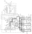
- FIG. 16 is a diagram illustrating the flow of refrigerant and water when the secondary cycle circuit is operated in the heating operation mode of the heat pump according to the third embodiment.
- FIG. 17 is a Ph diagram when the secondary cycle is operated in the heating operation mode of the heat pump according to the third embodiment.
- the refrigerant states a to g shown in FIG. 17 are refrigerant states at the locations shown in FIG.
- the piping represented by the solid line indicates the piping through which the refrigerant circulates
- the piping represented by the thick line illustrates the piping through which the water circulates.
- the flow of the primary side refrigerant and water shown in FIG. 10 and the flow of the primary side refrigerant and water shown in FIG. 16 are the same except that the secondary side refrigerant circulates in the secondary side refrigeration cycle circuit.
- the primary side refrigerant (point c) exiting the intermediate heat exchanger 40a is heated to the secondary side refrigerant in the first heat exchange section 51 (point d). For this reason, the temperature of the primary side refrigerant
- FIG. 18 is a diagram illustrating the flow of refrigerant and water when the secondary cycle is operated in the cooling main operation mode of the heat pump according to the third embodiment.
- FIG. 19 is a Ph diagram when the secondary cycle is operated in the cooling main operation mode of the heat pump according to the third embodiment.
- the refrigerant states a to h shown in FIG. 19 are refrigerant states at the locations shown in FIG.
- a pipe represented by a solid line indicates a pipe through which the refrigerant circulates
- a pipe represented by a thick line illustrates a pipe through which water circulates.
- the flow of the primary side refrigerant and water shown in FIG. 18 and the flow of the primary side refrigerant and water shown in FIG. 12 are the same except that the secondary side refrigerant circulates in the secondary side refrigeration cycle circuit.
- the primary side refrigerant (point c) exiting the intermediate heat exchanger 40a is heated to the secondary side refrigerant in the first heat exchange section 51 (point d). For this reason, the temperature of the primary side refrigerant
- FIG. 20 is a refrigerant circuit diagram illustrating another example of the heat pump according to the third embodiment.
- the heat pump 105 according to the third embodiment is different from the heat pump 104 in that check valves 35 to 38 as flow path switching valves are not provided.
- the direction of the refrigerant flowing through the first connection pipe 26 and the direction of the refrigerant flowing through the second connection pipe 27 are reversed from those of the heat pump 104.
- the opening and closing of the electromagnetic valves 28a to 28d is reversed from that of the heat pump 104.
- COP can be greatly improved by operating the above-mentioned secondary side refrigeration cycle circuit in the heating operation mode and the cooling main operation mode.
- FIG. 21 is a refrigerant circuit diagram illustrating still another example of the heat pump according to the third embodiment.
- the heat pump 106 according to the third embodiment is provided with a water pipe 44 that connects a water pipe downstream of the pump 41b and a water pipe upstream of the intermediate heat exchanger 40a.
- the water pipe 44 is provided with a flow path switching valve 44c.
- a flow path switching valve 44b is provided on the downstream side of the connection with the water pipe 44 in the water pipe downstream of the pump 41b.
- the water pipe upstream of the intermediate heat exchanger 40 a is provided with a flow path switching valve 44 a on the upstream side of the connection with the water pipe 44.
- Other configurations are the same as those of the heat pump 104.
- the intermediate heat exchangers 40a and 40b can be connected in series to the water side circuit by closing the flow path switching valves 44a and 44b and opening the flow path switching valve 44c. Moreover, the intermediate heat exchangers 40a and 40b can be connected in parallel by opening the flow path switching valves 44a and 44b and closing the flow path switching valve 44c.
- the intermediate heat exchangers 40a and 40b are connected in series, and in the other operation modes, the intermediate heat exchangers 40a and 40b are connected in parallel.
- the intermediate heat exchangers 40a and 40b can be connected in series during the heating operation to increase the flow rate of water, and heat can be exchanged efficiently.
- the COP can be greatly improved by operating the above-described secondary side refrigeration cycle circuit in the heating operation mode and the cooling main operation mode.
- FIG. 22 is a refrigerant circuit diagram illustrating still another example of the heat pump according to the third embodiment.
- the heat pump 107 according to the third embodiment connects the discharge pipe of the compressor 1 and the electromagnetic valves 28a and 28b so that the refrigerant discharged from the compressor 1 flows directly into the intermediate heat exchangers 40a and 40b.
- the third connection pipe 45 is different from the heat pump 105 in that the third connection pipe 45 is provided.
- the second flow rate control device 32 may be provided in the heat source device A or the relay device B as long as it is provided in the second connection pipe 27.
- the intermediate heat exchanger that performs heating in the cooling main operation mode and the heat source side heat exchanger 23 were connected in series. Further, the intermediate heat exchanger that performs cooling in the heating main operation mode and the heat source side heat exchanger 23 are connected in series.
- the intermediate heat exchanger that performs heating in the cooling main operation mode and the heat source side heat exchanger 23 are connected in parallel. Further, the intermediate heat exchanger that performs cooling in the heating main operation mode and the heat source side heat exchanger 23 are connected in parallel. Also in this circuit, the COP can be greatly improved by operating the above-described secondary refrigeration cycle circuit in the heating operation mode.
- heat pumps 105 to 107 may be circuits without the internal heat exchanger 34 or the second bypass pipe 39b.
- heat pump 107 it is good also as a circuit which connects a water side circuit so that intermediate heat exchangers 40a and 40b may be in series.
- the four-way switching valve 22 of the heat pumps 104 to 107 is not limited to this, and a plurality of on-off valves (electromagnetic valves) and three-way valves may be installed to substitute the circuit switching function.
- the COP can be greatly improved.
- heat is transferred to the indoor units C, D, and E by water. For this reason, even if a primary side refrigerant
- a flow control device is usually installed in the vicinity of the indoor units C, D, E.
- the temperature of the water flowing through the water pipe does not change due to pressure loss. It becomes possible to install. That is, the air conditioning target space can be air-conditioned by controlling the temperature difference of the water going back and forth by the opening degree control of the flow rate adjusting device 43c installed in the relay unit B. Since the flow rate adjusting device 43c is away from the air-conditioning target space, noise to the air-conditioning target space, such as driving of the control valve and the flow sound of the refrigerant when passing through the valve, can be reduced.
- the flow rate adjusting device 43c when the flow rate adjusting device 43c is installed in the relay machine B, the flow rate adjusting device 43c connected to the indoor heat exchangers 25c, 25d, 25e can be collectively controlled by the relay machine B.
- the control in the indoor units C, D, and E need only control the fan based on information such as the setting status of the indoor unit remote control, the thermo-off, and whether the heat source unit A is defrosting.
- the pumps 41a and 41b used for driving the water can be reduced in size, and further, the water transport power can be reduced to save energy. be able to.
Abstract
Description
特許文献1では、ガスクーラーに流入する水の流入温度に応じたガスクーラーの接続方法(直列接続や並列接続)が提案されている。そして、ガスクーラーに流入する水の流入温度に応じた接続方法でガスクーラーを配置し、ガスクーラーを流れる冷媒の熱エネルギーをカスケード利用することにより、COPの向上を図っている。 For example,
In
例えば、特許文献1に記載のヒートポンプは、ガスクーラーに流入する水の温度をあらかじめ仮定し、その温度に基づいてガスクーラーが配置されるものである。このため、ガスクーラーに流入する水の温度が仮定値よりも高くなった場合、COPが低下してしまう。
また、特許文献2に記載のヒートポンプは、冷凍能力の向上を図ったものである。 However, in the conventional heat pump, when the temperature of a medium to be heated (air, water, brain, etc.) flowing into the radiator during hot water supply or heating operation becomes high, the heating / hot water supply capacity decreases. was there.
For example, in the heat pump described in
Moreover, the heat pump described in
したがって、放熱器に流入する暖房や給湯等に用いる被加熱媒体の温度が上昇した場合でも、COPが高い状態で運転することが可能なヒートポンプを得ることができる。 In the present invention, at least one of the second and subsequent radiators is provided with a first heat exchange unit that heats the first refrigerant in the refrigerant pipe on the refrigerant inlet side of the radiator. . For this reason, even when the inflow temperature of the heated medium used for heating or hot water flowing into the radiator increases, the temperature difference between the heated medium and the first refrigerant can be secured in the second and subsequent radiators. Further, among the radiators provided with the first heat exchange unit, the radiator disposed at the most upstream part or the radiator downstream of the radiator is connected to the refrigerant pipe on the refrigerant outlet side. A second heat exchanging unit that cools one refrigerant is provided. For this reason, the enthalpy difference of the 1st refrigerant | coolant which flows through an evaporator can be enlarged. Therefore, the heat collecting ability in the evaporator is improved, and the efficiency (heating ability) of the heat pump is improved.
Therefore, it is possible to obtain a heat pump that can be operated with a high COP even when the temperature of a medium to be heated used for heating, hot water supply or the like flowing into the radiator increases.
図1は、実施の形態1に係るヒートポンプの一例を示す冷媒回路図である。なお、ヒートポンプとは、給湯や空気調和を行う冷凍装置を指す。
ヒートポンプ100は、第1の圧縮機1、第1の放熱器2、第2の放熱器4、膨張弁6及び蒸発器7が冷媒配管で接続され、一次側冷凍サイクル回路が形成されている。このヒートポンプ100は、例えば暖房用に用いられるものであり、ファン等(図示せず)によって供給された空気(第1の放熱器2及び第2の放熱器4)を、第1の放熱器2及び第2の放熱器4を流れる一次側冷媒で加熱する。本実施の形態1では、一次側冷媒として、放熱過程において超臨界状態で動作する冷媒(例えば二酸化炭素)を用いている。
ここで、膨張弁6が本発明の第1の減圧装置に相当し、一次側冷凍サイクル回路が本発明の第1の冷凍サイクル回路に相当する。また、一次側冷媒が、本発明の第1の冷媒に相当する。なお、第1の減圧装置は膨張弁6に限らず、種々のものを用いることができる。例えば、第1の減圧装置としてキャピラリー等を用いてもよい。
1 is a refrigerant circuit diagram illustrating an example of a heat pump according to
In the
Here, the
また、この一次側冷凍サイクル回路には、第2の放熱器4の下流側配管に第2の熱交換部5が設けられている。この第2の熱交換部5は、一次側冷凍サイクル回路を流れる一次側冷媒を冷却するものである。 In the primary side refrigeration cycle circuit, the first
Further, in the primary side refrigeration cycle circuit, a second
図2は、実施の形態1に係るヒートポンプの別の一例を示す冷媒回路図である。ポンプ8を介して、水が第1の放熱器2及び第2の放熱器4に直列に供給される。また、第1の放熱器2及び第2の放熱器4において、一次側冷媒の流れ方向と水の流れ方向とは対向流となっている。一次側冷媒の流れ方向と水の流れ方向とを対向流とすることにより、一次側冷媒と水との温度差を確保しやすくなり、熱交換効率が向上する。 For example, when a water heat exchanger is used as the
FIG. 2 is a refrigerant circuit diagram illustrating another example of the heat pump according to the first embodiment. Water is supplied in series to the
続いて、ヒートポンプ100~102の動作について説明する。
第1の圧縮機1は、蒸発器7で蒸発された冷媒を、アキュムレーター(図示せず)を介して吸引する。そして、通常運転時、第1の圧縮機1は、一次側冷媒を臨界圧力以上まで圧縮する。なお、アキュムレーターは設けなくてもよい。 (Description of operation)
Next, the operation of the
The
したがって、第1の放熱器2や第2の放熱器4に流入する被加熱媒体の温度が上昇した場合でも、COPが高い状態で運転することが可能なヒートポンプを得ることができる。 As described above, in the
Therefore, even when the temperature of the heated medium flowing into the
本発明に係るヒートポンプを、例えば以下のように構成してもよい。なお、本実施の形態2において、特に記述しない項目については実施の形態1と同様とし、同一の機能や構成については同一の符号を用いて述べることとする。
For example, the heat pump according to the present invention may be configured as follows. In the second embodiment, items that are not particularly described are the same as those in the first embodiment, and the same functions and configurations are described using the same reference numerals.
本実施の形態2に係るヒートポンプ103の一次側冷凍サイクル回路は、実施の形態1の図1で示したヒートポンプ100の一次側冷凍サイクル回路と同様の構成となっている。しかしながら、第1の熱交換部3及び第2の熱交換部5を構成要素に含む二次側冷凍サイクル回路が設けられている点において、実施の形態1の図1で示したヒートポンプ100と異なる。 FIG. 4 is a refrigerant circuit diagram illustrating an example of a heat pump according to the second embodiment.
The primary side refrigeration cycle circuit of the
このように構成されたヒートポンプ103を動作させた場合、一次側冷媒のP-h線図は、以下のようになる。
図5は、実施の形態2に係るヒートポンプにおいて、二次側冷凍サイクル回路を動作させなかった場合における一次側冷媒のP-h線図である。また、図6は、実施の形態2に係るヒートポンプにおいて、二次側冷凍サイクルを動作させた場合における一次側冷媒のP-h線図である。
なお、図5及び図6に示すa~eは、図4に示すa~eの位置での冷媒状態である。また、図5及び図6は、第2の放熱器4に流入する被加熱媒体の温度TがT1[℃]の場合を示している。 (Description of operation)
When the
FIG. 5 is a Ph diagram of the primary refrigerant when the secondary refrigeration cycle circuit is not operated in the heat pump according to the second embodiment. FIG. 6 is a Ph diagram of the primary refrigerant when the secondary refrigeration cycle is operated in the heat pump according to the second embodiment.
Note that a to e shown in FIGS. 5 and 6 are refrigerant states at the positions a to e shown in FIG. 5 and 6 show a case where the temperature T of the heated medium flowing into the
また、第2の放熱器4で被加熱媒体を加熱するためには、第2の放熱器4出口における一次側冷媒の温度をT1[℃]よりも大きくする必要がある(d)。そして、第2の放熱器4を流出した一次側冷媒は冷却されることなく膨張弁6へ流入する(e)。このため、第2の放熱器4に流入する被加熱媒体の温度が高くなった場合、蒸発器7を流れる一次側冷媒のエンタルピー差が小さくなってしまい、ヒートポンプ103の暖房能力が低下する。 As shown in FIG. 5, when the secondary refrigeration cycle circuit is not operated, the primary refrigerant flowing out of the
Moreover, in order to heat a to-be-heated medium with the
また、第2の放熱器4を流出した一次側冷媒は、第2の熱交換部5で冷却された後に膨張弁6へ流入する(d→e)。このため、膨張弁6に流入する一次側冷媒の温度をT1[℃]よりも小さくすることができる。したがって、第2の放熱器4に流入する被加熱媒体の温度が高くなった場合でも、蒸発器7を流れる一次側冷媒のエンタルピー差を大きくすることができ、ヒートポンプ103の暖房能力を向上させることができる。 On the other hand, when the secondary side refrigeration cycle circuit is operated as shown in FIG. 6, the primary side refrigerant flowing out of the
The primary refrigerant that has flowed out of the
例えば、以下のような空気調和装置に、本発明に係るヒートポンプを用いてもよい。なお、本実施の形態3において、特に記述しない項目については実施の形態1又は実施の形態2と同様とし、同一の機能や構成については同一の符号を用いて述べることとする。
For example, you may use the heat pump which concerns on this invention for the following air conditioning apparatuses. In
本実施の形態3に係るヒートポンプ104は、熱源機A(室外機)、中継機B、及び複数の室内機(室内機C,D,E)を配管接続することにより、互いに離して設置することができる多室型空気調和装置である。例えばビルの屋上に熱源機Aを、ビルの各階の天井裏に中継機Bを、各部屋に室内機C,D,Eを設置することができる。また、ヒートポンプ104は、各室内機毎に冷房又は暖房の設定をすることが可能な空気調和装置である。 FIG. 7 is a refrigerant circuit diagram illustrating an example of a heat pump according to the third embodiment.
The
熱源機Aから中継機Bまでの熱輸送は、二酸化炭素等、圧縮機21から吐出される圧力が臨界圧力よりも高い状態となる冷媒により行われる。中継機Bから室内機C,D,Eまでの熱輸送は、水によって行われる。中継機Bから室内機C,D,Eまでの熱輸送は、不凍液、不凍液と水の混合液、水と防食効果が高い添加剤の混合液等のブラインを用いてもよい。 The
熱源機Aは、圧縮機21、圧縮機21から吐出された冷媒の流通方向を切り替える四方切替弁22、熱源側熱交換器23(室外熱交換器)、アキュムレーター24、及び逆止弁35~38で構成される流路切替弁等を備えている。なお、以後は熱源側熱交換器23の一例として、空冷式の熱源側熱交換器を用いて説明するが、冷媒が他の流体と熱交換する形態であれば水冷式等他の方式でもよい。 (Heat source machine A)
The heat source machine A includes a
逆止弁35は、熱源側熱交換器23と第2の接続配管27との間に設けられており、熱源側熱交換器23から第2の接続配管27へのみ冷媒流通を許容する。逆止弁36は、熱源機Aの四方切替弁22と第1の接続配管26との間に設けられており、第1の接続配管26から四方切替弁22へのみ冷媒流通を許容する。逆止弁37は、熱源機Aの四方切替弁22と第2の接続配管27との間に設けられており、四方切替弁22から第2の接続配管27へのみ冷媒流通を許容する。逆止弁38は、熱源側熱交換器23と第1の接続配管26との間に設けられており、第1の接続配管26から熱源側熱交換器23へのみ冷媒流通を許容する。
なお、第2の接続配管27の他方の端部は、後述する中継機Bのバイパス配管39aと接続されている。また、第1の接続配管26の他方の端部は、後述する中継機Bの第1の分岐部30と接続されている。 The flow path switching valve includes four check valves (
The
The other end of the
室内機C,D,Eのそれぞれは、同様の構成となっている。
より詳しくは、室内機Cは室内熱交換器25cを備えている。室内熱交換器25cの一方の端部は、第1の接続配管26cを介して、後述する中継機Bの流路切替弁42i,42lと接続されている。室内熱交換器25cの他方の端部は、第2の接続配管27cを介して、後述する中継機Bの流路切替弁42c,42fと接続されている。また、室内熱交換器25cと流路切替弁42c,42fとの間の第2の接続配管27cには、流量制御装置43cが設けられている。流量制御装置43cは、室内熱交換器25cと流路切替弁42i,42lとの間の第1の接続配管26cに設けられていてもよい。 (Indoor unit)
Each of the indoor units C, D, and E has the same configuration.
More specifically, the indoor unit C includes an
第2の接続配管27c,27d,27eは、水が流れる配管である。第1の接続配管26c,26d,26eを流れる水の密度と第2の接続配管27c,27d,27eを流れる水の密度はほぼ同じであるため、これら配管の管径は同じにしてもよい。 The
中継機Bは、中間熱交換器40(中間熱交換器40a,40b)、第1の流量制御装置29a,29b、第1の分岐部30、第2の分岐部31、第2の流量制御装置32、及び第3の流量制御装置33等が配管接続された一次側冷凍サイクル回路を有している。また、中継機Bは、第2の圧縮機50、第1の熱交換部51、膨張弁52、及び第2の熱交換部53が配管接続された2次側冷凍サイクル回路を備えている。 (Repeater B)
The relay B includes an intermediate heat exchanger 40 (
電磁弁28a,28cのそれぞれの一方の端部は、中間熱交換器40aと接続されている。また、電磁弁28aの他方の端部は、第2の接続配管27と接続されている。電磁弁28cの他方の端部は、第1の接続配管26と接続されている。
電磁弁28b,28dのそれぞれの一方の端部は、中間熱交換器40bと接続されている。そして、電磁弁28bと中間熱交換器40bとを接続する配管には、第1の熱交換部51が設けられている。また、電磁弁28bの他方の端部は、第2の接続配管27と接続されている。電磁弁28dの他方の端部は、第1の接続配管26と接続されている。 The
One end of each of the
One end of each of the
続いて、このヒートポンプ104が実行する各種運転時の運転動作について説明する。ヒートポンプ104の運転動作には、室内機の冷房運転、暖房運転の設定に応じて、冷房運転、暖房運転、冷房主体運転及び暖房主体運転の4つのモードがある。 <Description of operation>
Then, the operation | movement operation | movement at the time of the various driving | running which this
図8は、実施の形態3に係るヒートポンプにおける冷房運転時の冷媒、水の流れを示す冷媒回路図である。また、図9は、実施の形態3に係るヒートポンプにおける冷房運転時のP-h線図である。なお、図9に示すa~fの冷媒状態は、それぞれ図8に示す箇所での冷媒状態である。
ここでは、室内機C,D,Eの全てが冷房運転しようとしている場合について説明する。冷房運転モードでは、四方切替弁22を、圧縮機21から吐出された冷媒が熱源側熱交換器23へ流入するように切り替える。また、電磁弁28c,28dは開いた状態、電磁弁28a,28bは閉じた状態、電磁弁28eは閉じた状態となる。なお、実線で表された配管が冷媒の循環する配管を、太線で表された配管が水の循環する配管を示す。 [Cooling operation mode]
FIG. 8 is a refrigerant circuit diagram illustrating the flow of refrigerant and water during cooling operation in the heat pump according to the third embodiment. FIG. 9 is a Ph diagram during cooling operation of the heat pump according to the third embodiment. Note that the refrigerant states a to f shown in FIG. 9 are refrigerant states at the locations shown in FIG.
Here, a case will be described in which all of the indoor units C, D, and E are about to perform a cooling operation. In the cooling operation mode, the four-
図10は、実施の形態3に係るヒートポンプにおける暖房運転時の冷媒、水の流れを示す冷媒回路図である。また、図11は、実施の形態3に係るヒートポンプにおける暖房運転時のP-h線図である。なお、図11に示すa~gの冷媒状態は、それぞれ図10に示す箇所での冷媒状態である。
ここでは、室内機C,D,Eの全てが暖房運転しようとしている場合について説明する。暖房運転モードでは、四方切替弁22を、圧縮機21から吐出された冷媒が第1の分岐部30へ流入するように切り替える。また、電磁弁28aは開いた状態、電磁弁28b,28c,28dは閉じた状態となる。また、電磁弁28eは開いた状態となっており、中間熱交換器40aと中間熱交換器40bは直列接続された状態となる。なお、実線で表された配管が冷媒の循環する配管を、太線で表された配管が水の循環する配管を示す。 [Heating operation mode]
FIG. 10 is a refrigerant circuit diagram illustrating the flow of refrigerant and water during heating operation in the heat pump according to the third embodiment. FIG. 11 is a Ph diagram during heating operation in the heat pump according to the third embodiment. Note that the refrigerant states a to g shown in FIG. 11 are refrigerant states at the locations shown in FIG.
Here, a case where all of the indoor units C, D, and E are going to perform a heating operation will be described. In the heating operation mode, the four-
図12は、実施の形態3に係るヒートポンプにおける冷房主体運転時の冷媒、水の流れを示す冷媒回路図である。また、図13は、実施の形態3に係るヒートポンプにおける冷房主体運転時のP-h線図である。なお、図13に示すa~hの冷媒状態は、それぞれ図12に示す箇所での冷媒状態である。
ここでは、室内機C,Dが冷房を、室内機Eが暖房をしている場合について説明する。冷房主体運転モードでは、四方切替弁22を、圧縮機21から吐出された冷媒が熱源側熱交換器23へ流入するように切り替える。また、電磁弁28b,28cは開いた状態、電磁弁28a,28dは閉じた状態、電磁弁28eは閉じた状態となる。冷房主体運転モードでは、中間熱交換器40aが冷水を作り、中間熱交換器40bが温水を作る。また、熱源側熱交換器23と温水を作る中間熱交換器40bが放熱器として直列に接続されている。なお、実線で表された配管が冷媒の循環する配管を、太線で表された配管が水の循環する配管を示す。 [Cooling operation mode]
FIG. 12 is a refrigerant circuit diagram illustrating the flow of refrigerant and water during the cooling main operation in the heat pump according to the third embodiment. FIG. 13 is a Ph diagram during cooling main operation in the heat pump according to the third embodiment. Note that the refrigerant states a to h shown in FIG. 13 are refrigerant states at the locations shown in FIG.
Here, the case where the indoor units C and D are cooling and the indoor unit E is heating will be described. In the cooling main operation mode, the four-
つまり、ポンプ41bによって室内熱交換器25eに流入した温水が、室内機Eの設置された空調対象空間を暖房する。このとき、室内機Eの設置された室内の暖房負荷等に応じて流量制御装置43cの開度を制御することにより、室内熱交換器25eへ流入する水の流量が制御される。また、ポンプ41aによって室内熱交換器25c,25dに流入した冷水が、室内機C,Dの設置された空調対象空間を冷房する。このとき、室内機C,Dの設置された室内の冷房負荷等に応じて流量制御装置43cの開度を制御することにより、室内熱交換器25c,25dへ流入する水の流量が制御される。 In the cooling main operation mode, a flow path in which the
That is, the hot water flowing into the
図14は、実施の形態3に係るヒートポンプにおける暖房主体運転時の冷媒、水の流れを示す冷媒回路図である。また、図15は、実施の形態3に係るヒートポンプにおける暖房主体運転時のP-h線図である。なお、図15に示すa~eの冷媒状態は、それぞれ図14に示す箇所での冷媒状態である。
ここでは、室内機Cが冷房を、室内機D,Eが暖房をしている場合について説明する。暖房主体運転モードでは、四方切替弁22を、圧縮機21から吐出された冷媒が第1の分岐部30へ流入するように切り替える。また、電磁弁28b,28cは開いた状態、電磁弁28a,28dは閉じた状態、電磁弁28eは閉じた状態となる。暖房主体運転モードでは、中間熱交換器40aが冷水を作り、中間熱交換器40bが温水を作る。なお、実線で表された配管が冷媒の循環する配管を、太線で表された配管が水の循環する配管を示す。 [Heating main operation mode]
FIG. 14 is a refrigerant circuit diagram illustrating the flow of refrigerant and water during heating main operation in the heat pump according to the third embodiment. FIG. 15 is a Ph diagram during heating main operation in the heat pump according to the third embodiment. Note that the refrigerant states a to e shown in FIG. 15 are refrigerant states at the locations shown in FIG.
Here, the case where the indoor unit C is cooling and the indoor units D and E are heating will be described. In the heating main operation mode, the four-
つまり、ポンプ41bによって室内熱交換器25d,25eに流入した温水が、室内機D,Eの設置された空調対象空間を暖房する。このとき、室内機D,Eの設置された室内の暖房負荷等に応じて流量制御装置43cの開度を制御することにより、室内熱交換器25d,25eへ流入する水の流量が制御される。また、ポンプ41aによって室内熱交換器25cに流入した冷水が、室内機Cの設置された空調対象空間を冷房する。このとき、室内機Cの設置された室内の冷房負荷等に応じて流量制御装置43cの開度を制御することにより、室内熱交換器25cへ流入する水の流量が制御される。 In the cooling main operation mode, a flow path in which the
That is, the hot water flowing into the
図16は、実施の形態3に係るヒートポンプの暖房運転モードにおいて二次側サイクル回路を動作させた場合の冷媒、水の流れを示す図である。また、図17は、実施の形態3に係るヒートポンプの暖房運転モードにおいて二次側サイクルを動作させた場合のP-h線図である。なお、図17に示すa~gの冷媒状態は、それぞれ図16に示す箇所での冷媒状態である。また、図16では、実線で表された配管が冷媒の循環する配管を、太線で表された配管が水の循環する配管を示す。
二次側冷凍サイクル回路に二次側冷媒が循環している以外、図10に示す一次側冷媒及び水の流れと図16に示す一次側冷媒及び水の流れは同様である。 [Heating operation mode]
FIG. 16 is a diagram illustrating the flow of refrigerant and water when the secondary cycle circuit is operated in the heating operation mode of the heat pump according to the third embodiment. FIG. 17 is a Ph diagram when the secondary cycle is operated in the heating operation mode of the heat pump according to the third embodiment. Note that the refrigerant states a to g shown in FIG. 17 are refrigerant states at the locations shown in FIG. Moreover, in FIG. 16, the piping represented by the solid line indicates the piping through which the refrigerant circulates, and the piping represented by the thick line illustrates the piping through which the water circulates.
The flow of the primary side refrigerant and water shown in FIG. 10 and the flow of the primary side refrigerant and water shown in FIG. 16 are the same except that the secondary side refrigerant circulates in the secondary side refrigeration cycle circuit.
図18は、実施の形態3に係るヒートポンプの冷房主体運転モードにおいて二次側サイクルを動作させた場合の冷媒、水の流れを示す図である。また、図19は、実施の形態3に係るヒートポンプの冷房主体運転モードにおいて二次側サイクルを動作させた場合のP-h線図である。なお、図19に示すa~hの冷媒状態は、それぞれ図18に示す箇所での冷媒状態である。また、図18では、実線で表された配管が冷媒の循環する配管を、太線で表された配管が水の循環する配管を示す。
二次側冷凍サイクル回路に二次側冷媒が循環している以外、図18に示す一次側冷媒及び水の流れと図12に示す一次側冷媒及び水の流れは同様である。 [Cooling operation mode]
FIG. 18 is a diagram illustrating the flow of refrigerant and water when the secondary cycle is operated in the cooling main operation mode of the heat pump according to the third embodiment. FIG. 19 is a Ph diagram when the secondary cycle is operated in the cooling main operation mode of the heat pump according to the third embodiment. Note that the refrigerant states a to h shown in FIG. 19 are refrigerant states at the locations shown in FIG. Further, in FIG. 18, a pipe represented by a solid line indicates a pipe through which the refrigerant circulates, and a pipe represented by a thick line illustrates a pipe through which water circulates.
The flow of the primary side refrigerant and water shown in FIG. 18 and the flow of the primary side refrigerant and water shown in FIG. 12 are the same except that the secondary side refrigerant circulates in the secondary side refrigeration cycle circuit.
本実施の形態3に係るヒートポンプ105は、流路切替弁としての逆止弁35~38を設けていない点がヒートポンプ104と異なる。この回路においては、暖房運転モード及び暖房主体運転モードにおいて、第1の接続配管26を流れる冷媒の向きと第2の接続配管27を流れる冷媒の向きがヒートポンプ104とは逆転する。また、暖房運転モード及び暖房主体運転モードにおいて、電磁弁28a~28dの開閉が、ヒートポンプ104とは逆転する。この冷媒回路においても、暖房運転モードと冷房主体運転モードにおいて前述の二次側冷凍サイクル回路を動作させることにより、COPを大幅に向上させることができる。 FIG. 20 is a refrigerant circuit diagram illustrating another example of the heat pump according to the third embodiment.
The
本実施の形態3に係るヒートポンプ106は、ポンプ41bの下流の水配管と中間熱交換器40aの上流の水配管とを接続する水配管44が設けられている。この水配管44には、流路切替弁44cが設けられている。また、ポンプ41bの下流の水配管には、水配管44との接続部より下流側に、流路切替弁44bが設けられている。また、中間熱交換器40aの上流の水配管には、水配管44との接続部より上流側に、流路切替弁44aが設けられている。その他の構成は、ヒートポンプ104と同様である。 FIG. 21 is a refrigerant circuit diagram illustrating still another example of the heat pump according to the third embodiment.
The
本実施の形態3に係るヒートポンプ107は、圧縮機1から吐出された冷媒が直接中間熱交換器40a,40bに流入するように、圧縮機1の吐出配管と電磁弁28a,28bとを接続する第3の接続配管45を設けた点がヒートポンプ105と異なる。なお、第2の流量制御装置32は、第2の接続配管27に設けられれば、熱源機Aにあってもよいし中継機Bにあってもよい。 FIG. 22 is a refrigerant circuit diagram illustrating still another example of the heat pump according to the third embodiment.
The
また、熱源機Aから中継機Bまでの熱輸送を一次側冷媒で行なうことにより、水の駆動に使用するポンプ41a,41bを小型化でき、さらに水の搬送動力を低減させて省エネルギー化を図ることができる。 In addition, when the flow
Further, by performing heat transport from the heat source unit A to the relay unit B with the primary side refrigerant, the
Claims (8)
- 第1の圧縮機、複数の放熱器、第1の減圧装置及び蒸発器が冷媒配管により接続されて第1の冷凍サイクル回路が形成され、該第1の冷凍サイクル回路に第1の冷媒が循環するヒートポンプにおいて、
複数の前記放熱器は直列接続され、
前記第1の冷媒の流れ方向に沿って見た場合、
2番目以降の前記放熱器のうちの少なくとも1つには、該放熱器の冷媒入口側となる冷媒配管に、前記第1の冷媒を加熱する第1の熱交換部が設けられ、
前記第1の熱交換部が設けられた前記放熱器のうちで最上流部に配置された前記放熱器又は当該放熱器よりも下流側の前記放熱器には、冷媒出口側となる冷媒配管に、前記第1の冷媒を冷却する第2の熱交換部が設けられていることを特徴とするヒートポンプ。 A first compressor, a plurality of radiators, a first pressure reducing device, and an evaporator are connected by a refrigerant pipe to form a first refrigeration cycle circuit, and the first refrigerant circulates in the first refrigeration cycle circuit. In the heat pump that
The plurality of radiators are connected in series,
When viewed along the flow direction of the first refrigerant,
At least one of the second and subsequent radiators is provided with a first heat exchange unit that heats the first refrigerant in a refrigerant pipe on the refrigerant inlet side of the radiator,
Among the radiators provided with the first heat exchange section, the radiator disposed in the most upstream part or the radiator on the downstream side of the radiator is provided with a refrigerant pipe on the refrigerant outlet side. A heat pump characterized in that a second heat exchanging part for cooling the first refrigerant is provided. - 第2の圧縮機及び第2の減圧装置を備え、
前記第2の圧縮機、前記第1の熱交換部のうちの少なくとも1つ、前記第2の減圧装置及び前記第2の熱交換部が冷媒配管により接続されて第2の冷凍サイクル回路が形成され、
該第2の冷凍サイクル回路に第2の冷媒が循環することを特徴とする請求項1に記載のヒートポンプ。 A second compressor and a second decompressor;
At least one of the second compressor, the first heat exchange unit, the second decompression device, and the second heat exchange unit are connected by a refrigerant pipe to form a second refrigeration cycle circuit. And
The heat pump according to claim 1, wherein the second refrigerant circulates in the second refrigeration cycle circuit. - 前記第1の冷媒は、前記第1の圧縮機から吐出される際の圧力が臨界圧力よりも高い状態で動作する冷媒であることを特徴とする請求項1又は請求項2に記載のヒートポンプ。 The heat pump according to claim 1 or 2, wherein the first refrigerant is a refrigerant that operates in a state in which a pressure when discharged from the first compressor is higher than a critical pressure.
- 前記第1の減圧装置に流入する前記第1の冷媒の温度は、
複数の前記放熱器に流入する被加熱媒体の温度よりも低くなるように制御されることを特徴とする請求項1~請求項3のいずれか一項に記載のヒートポンプ。 The temperature of the first refrigerant flowing into the first pressure reducing device is:
The heat pump according to any one of claims 1 to 3, wherein the heat pump is controlled to be lower than a temperature of a medium to be heated that flows into the plurality of radiators. - 前記第1の熱交換部及び前記第2の熱交換部において、
前記第1の冷媒の流れ方向と前記第2の冷媒の流れ方向とが対向流となることを特徴とする請求項2に記載のヒートポンプ。 In the first heat exchange unit and the second heat exchange unit,
The heat pump according to claim 2, wherein the flow direction of the first refrigerant and the flow direction of the second refrigerant are opposed to each other. - 前記第2の冷媒は、
蒸発温度が10℃~30℃、擬臨界温度又は凝縮温度が30℃~50℃における理論COPが、蒸発温度が10℃~30℃、擬臨界温度又は凝縮温度が30℃~50℃における前記第1の冷媒の理論COPよりも高い冷媒であることを特徴とする請求項2又は請求項5に記載のヒートポンプ。 The second refrigerant is
The theoretical COP when the evaporation temperature is 10 ° C. to 30 ° C. and the pseudocritical temperature or the condensation temperature is 30 ° C. to 50 ° C. is the same as the theoretical COP when the evaporation temperature is 10 ° C. to 30 ° C. The heat pump according to claim 2 or 5, wherein the heat pump is higher than a theoretical COP of one refrigerant. - 前記第1の冷媒は、R410A冷媒よりも地球温暖化係数が小さい冷媒であることを特徴とする請求項1~請求項6のいずれか一項に記載のヒートポンプ。 The heat pump according to any one of claims 1 to 6, wherein the first refrigerant is a refrigerant having a global warming potential smaller than that of the R410A refrigerant.
- 前記第2の冷媒は、R410A冷媒よりも地球温暖化係数が小さい冷媒であることを特徴とする請求項2,5,6のいずれか一項に記載のヒートポンプ。 The heat pump according to any one of claims 2, 5, and 6, wherein the second refrigerant is a refrigerant having a global warming potential smaller than that of the R410A refrigerant.
Priority Applications (5)
| Application Number | Priority Date | Filing Date | Title |
|---|---|---|---|
| PCT/JP2009/068358 WO2011052031A1 (en) | 2009-10-27 | 2009-10-27 | Heat pump |
| CN200980162230.5A CN102597658B (en) | 2009-10-27 | 2009-10-27 | Heat pump |
| EP09850811.2A EP2495510B1 (en) | 2009-10-27 | 2009-10-27 | Heat pump |
| JP2011538132A JP5496217B2 (en) | 2009-10-27 | 2009-10-27 | heat pump |
| US13/503,483 US9593872B2 (en) | 2009-10-27 | 2009-10-27 | Heat pump |
Applications Claiming Priority (1)
| Application Number | Priority Date | Filing Date | Title |
|---|---|---|---|
| PCT/JP2009/068358 WO2011052031A1 (en) | 2009-10-27 | 2009-10-27 | Heat pump |
Publications (1)
| Publication Number | Publication Date |
|---|---|
| WO2011052031A1 true WO2011052031A1 (en) | 2011-05-05 |
Family
ID=43921475
Family Applications (1)
| Application Number | Title | Priority Date | Filing Date |
|---|---|---|---|
| PCT/JP2009/068358 WO2011052031A1 (en) | 2009-10-27 | 2009-10-27 | Heat pump |
Country Status (5)
| Country | Link |
|---|---|
| US (1) | US9593872B2 (en) |
| EP (1) | EP2495510B1 (en) |
| JP (1) | JP5496217B2 (en) |
| CN (1) | CN102597658B (en) |
| WO (1) | WO2011052031A1 (en) |
Cited By (4)
| Publication number | Priority date | Publication date | Assignee | Title |
|---|---|---|---|---|
| JP2012243982A (en) * | 2011-05-20 | 2012-12-10 | Nippon Soken Inc | Cooling apparatus |
| EP2808625A4 (en) * | 2012-01-24 | 2016-04-06 | Mitsubishi Electric Corp | Coolant replenishment method for air-conditioning unit, and air-conditioning unit |
| JP2016151372A (en) * | 2015-02-17 | 2016-08-22 | 株式会社富士通ゼネラル | Air conditioner |
| JP2017133730A (en) * | 2016-01-26 | 2017-08-03 | 伸和コントロールズ株式会社 | Temperature control system |
Families Citing this family (27)
| Publication number | Priority date | Publication date | Assignee | Title |
|---|---|---|---|---|
| CN103797317B (en) * | 2011-09-13 | 2016-08-17 | 三菱电机株式会社 | Heat pump assembly and the control method of heat pump assembly |
| DE102012215971A1 (en) * | 2012-09-10 | 2014-05-28 | Bayerische Motoren Werke Aktiengesellschaft | Method for thermally conditioning an internal combustion engine and / or a passenger compartment of a vehicle and vehicle |
| DE102012222594B4 (en) * | 2012-12-10 | 2018-05-17 | Bayerische Motoren Werke Aktiengesellschaft | Method for operating a refrigerant circuit as a heat pump and as a heat pump operable refrigerant circuit |
| US9995509B2 (en) * | 2013-03-15 | 2018-06-12 | Trane International Inc. | Cascading heat recovery using a cooling unit as a source |
| US10060654B2 (en) * | 2014-10-16 | 2018-08-28 | Sanden Holdings Corporation | Heat pump type heating apparatus |
| CN104930578B (en) * | 2015-05-21 | 2018-05-01 | 广东美的暖通设备有限公司 | A kind of heat pump directly-heated type heating system with indoor unit |
| US10634394B2 (en) | 2015-12-18 | 2020-04-28 | Samsung Electronics Co., Ltd. | Air conditioner outdoor unit including heat exchange apparatus |
| JP2017116122A (en) * | 2015-12-18 | 2017-06-29 | 三星電子株式会社Samsung Electronics Co.,Ltd. | Heat exchange device |
| US10605494B2 (en) | 2017-01-03 | 2020-03-31 | Heatcraft Refrigeration Product LLC | System and method for reusing waste heat of a transcritical refrigeration system |
| US20180187927A1 (en) * | 2017-01-03 | 2018-07-05 | Heatcraft Refrigeration Products Llc | System and method for reusing waste heat of a transcritical refrigeration system |
| CN107024017A (en) * | 2017-03-23 | 2017-08-08 | 北京国科天创建筑设计院有限责任公司 | A kind of multiple stacked carbon dioxide heat pump system of high inflow temperature |
| CN107804142B (en) * | 2017-10-19 | 2023-08-08 | 珠海格力电器股份有限公司 | Heat pump system, electric automobile and heat pump control method of electric automobile |
| CN108106036B (en) * | 2017-12-05 | 2023-10-27 | 广东申菱环境系统股份有限公司 | Heat pump utilizing waste heat of cascade refrigeration system |
| US10648701B2 (en) * | 2018-02-06 | 2020-05-12 | Thermo Fisher Scientific (Asheville) Llc | Refrigeration systems and methods using water-cooled condenser and additional water cooling |
| KR20190120936A (en) * | 2018-04-17 | 2019-10-25 | 한온시스템 주식회사 | Heat management system of vehicle |
| IL260159B (en) * | 2018-06-19 | 2022-02-01 | N A M Tech Ltd | Multi cascade cooling system |
| JP6652219B1 (en) * | 2018-11-29 | 2020-02-19 | ダイキン工業株式会社 | Refrigerant leak determination system and refrigeration cycle device |
| CN109579191B (en) * | 2018-12-25 | 2021-07-13 | 荏原冷热系统(中国)有限公司 | Double-compressor air conditioning system and control method and control device for refrigerant circulation amount thereof |
| KR102533382B1 (en) * | 2019-01-09 | 2023-05-19 | 한온시스템 주식회사 | Thermal management system |
| CN111520932B8 (en) * | 2019-02-02 | 2023-07-04 | 开利公司 | Heat recovery enhanced refrigeration system |
| CN111520928B (en) | 2019-02-02 | 2023-10-24 | 开利公司 | Enhanced thermally driven injector cycling |
| CN110068219A (en) * | 2019-03-15 | 2019-07-30 | 南京航空航天大学 | Analysis of Heat Pump Drying System and its working method with heat-storing device |
| KR20200114123A (en) * | 2019-03-27 | 2020-10-07 | 엘지전자 주식회사 | An air conditioning apparatus |
| KR20210017119A (en) * | 2019-08-07 | 2021-02-17 | 현대자동차주식회사 | Air conditioning system for vehicle |
| WO2021181513A1 (en) * | 2020-03-10 | 2021-09-16 | Atsジャパン株式会社 | Refrigerant control system and refrigeration system |
| JP6978704B2 (en) * | 2020-03-31 | 2021-12-08 | ダイキン工業株式会社 | Water heating system |
| CN111550944B (en) * | 2020-04-26 | 2024-03-29 | 珠海格力电器股份有限公司 | Triple throttling enthalpy-increasing double-condensation refrigerating system, air conditioner and control method |
Citations (6)
| Publication number | Priority date | Publication date | Assignee | Title |
|---|---|---|---|---|
| JPH02290475A (en) * | 1989-04-28 | 1990-11-30 | Nippondenso Co Ltd | Heat pump type air conditioner |
| JP2004003801A (en) | 2002-04-26 | 2004-01-08 | Matsushita Electric Ind Co Ltd | Refrigeration equipment using carbon dioxide as refrigerant |
| JP2005090825A (en) * | 2003-09-16 | 2005-04-07 | Toshiba Kyaria Kk | Complex air-conditioner |
| WO2005052467A1 (en) * | 2003-11-28 | 2005-06-09 | Mitsubishi Denki Kabushiki Kaisha | Freezer and air contitioner |
| JP2007003169A (en) * | 2005-06-22 | 2007-01-11 | Noriyuki Yamauchi | Refrigeration, hot water supply, and heating system using carbon dioxide as refrigerant, and condensing system used therein |
| JP2008002759A (en) | 2006-06-23 | 2008-01-10 | Matsushita Electric Ind Co Ltd | Binary refrigerating system and cold storage |
Family Cites Families (8)
| Publication number | Priority date | Publication date | Assignee | Title |
|---|---|---|---|---|
| US3852974A (en) * | 1971-12-03 | 1974-12-10 | T Brown | Refrigeration system with subcooler |
| JP3985394B2 (en) | 1999-07-30 | 2007-10-03 | 株式会社デンソー | Refrigeration cycle equipment |
| JP4488712B2 (en) * | 2003-10-08 | 2010-06-23 | 三菱電機株式会社 | Air conditioner |
| KR100565257B1 (en) * | 2004-10-05 | 2006-03-30 | 엘지전자 주식회사 | Secondary refrigerant cycle using compressor and air conditioner having the same |
| JP3982545B2 (en) * | 2005-09-22 | 2007-09-26 | ダイキン工業株式会社 | Air conditioner |
| KR100803144B1 (en) * | 2007-03-28 | 2008-02-14 | 엘지전자 주식회사 | Air conditioner |
| JP2008267731A (en) * | 2007-04-23 | 2008-11-06 | Mitsubishi Electric Corp | Air-conditioning device |
| JP2008292122A (en) * | 2007-05-28 | 2008-12-04 | Kansai Electric Power Co Inc:The | Heat storage system and heat storage type air conditioner using same |
-
2009
- 2009-10-27 EP EP09850811.2A patent/EP2495510B1/en active Active
- 2009-10-27 WO PCT/JP2009/068358 patent/WO2011052031A1/en active Application Filing
- 2009-10-27 US US13/503,483 patent/US9593872B2/en active Active
- 2009-10-27 JP JP2011538132A patent/JP5496217B2/en active Active
- 2009-10-27 CN CN200980162230.5A patent/CN102597658B/en active Active
Patent Citations (6)
| Publication number | Priority date | Publication date | Assignee | Title |
|---|---|---|---|---|
| JPH02290475A (en) * | 1989-04-28 | 1990-11-30 | Nippondenso Co Ltd | Heat pump type air conditioner |
| JP2004003801A (en) | 2002-04-26 | 2004-01-08 | Matsushita Electric Ind Co Ltd | Refrigeration equipment using carbon dioxide as refrigerant |
| JP2005090825A (en) * | 2003-09-16 | 2005-04-07 | Toshiba Kyaria Kk | Complex air-conditioner |
| WO2005052467A1 (en) * | 2003-11-28 | 2005-06-09 | Mitsubishi Denki Kabushiki Kaisha | Freezer and air contitioner |
| JP2007003169A (en) * | 2005-06-22 | 2007-01-11 | Noriyuki Yamauchi | Refrigeration, hot water supply, and heating system using carbon dioxide as refrigerant, and condensing system used therein |
| JP2008002759A (en) | 2006-06-23 | 2008-01-10 | Matsushita Electric Ind Co Ltd | Binary refrigerating system and cold storage |
Cited By (4)
| Publication number | Priority date | Publication date | Assignee | Title |
|---|---|---|---|---|
| JP2012243982A (en) * | 2011-05-20 | 2012-12-10 | Nippon Soken Inc | Cooling apparatus |
| EP2808625A4 (en) * | 2012-01-24 | 2016-04-06 | Mitsubishi Electric Corp | Coolant replenishment method for air-conditioning unit, and air-conditioning unit |
| JP2016151372A (en) * | 2015-02-17 | 2016-08-22 | 株式会社富士通ゼネラル | Air conditioner |
| JP2017133730A (en) * | 2016-01-26 | 2017-08-03 | 伸和コントロールズ株式会社 | Temperature control system |
Also Published As
| Publication number | Publication date |
|---|---|
| US9593872B2 (en) | 2017-03-14 |
| US20120204596A1 (en) | 2012-08-16 |
| CN102597658A (en) | 2012-07-18 |
| EP2495510A4 (en) | 2016-10-12 |
| JPWO2011052031A1 (en) | 2013-03-14 |
| JP5496217B2 (en) | 2014-05-21 |
| EP2495510B1 (en) | 2017-08-16 |
| EP2495510A1 (en) | 2012-09-05 |
| CN102597658B (en) | 2014-10-22 |
Similar Documents
| Publication | Publication Date | Title |
|---|---|---|
| JP5496217B2 (en) | heat pump | |
| JP6685409B2 (en) | Air conditioner | |
| CN102597657B (en) | Air conditioning device | |
| WO2013111177A1 (en) | Air-conditioning unit | |
| WO2011048695A1 (en) | Air conditioning device | |
| CN102483250B (en) | Air conditioning device | |
| JP5774216B2 (en) | Multi-room air conditioner | |
| US20140007607A1 (en) | Air-conditioning apparatus | |
| US9625217B2 (en) | Heat exchanger and air conditioner including same | |
| WO2010137078A1 (en) | Refrigeration cycle device and air-conditioning device | |
| WO2015140951A1 (en) | Air conditioner | |
| JP5875710B2 (en) | Air conditioner | |
| WO2013146415A1 (en) | Heat pump-type heating device | |
| CN113339909B (en) | Heat pump air conditioning system | |
| EP2896911A1 (en) | Air conditioning apparatus | |
| CN107499089A (en) | A kind of electric automobile heat-pump air-conditioning system and its method of work | |
| US20130219944A1 (en) | Heat exchanger | |
| CN215930176U (en) | Refrigerating system | |
| KR20110074073A (en) | Refrigerating and freezing combine air conditioning system | |
| KR101146783B1 (en) | Refrigerant system | |
| KR20200114123A (en) | An air conditioning apparatus | |
| TW201945671A (en) | Air conditioner characterized in reducing heat loss of a four-way valve and improving COP by heating a gas-liquid two-phase refrigerant flowing out of an evaporator to a gas single phase before reaching the four-way valve | |
| JP6071540B2 (en) | Heat pump cold / hot water system | |
| KR101685846B1 (en) | An air conditioner | |
| JP4852408B2 (en) | Heat pump refrigeration system |
Legal Events
| Date | Code | Title | Description |
|---|---|---|---|
| WWE | Wipo information: entry into national phase |
Ref document number: 200980162230.5 Country of ref document: CN |
|
| 121 | Ep: the epo has been informed by wipo that ep was designated in this application |
Ref document number: 09850811 Country of ref document: EP Kind code of ref document: A1 |
|
| WWE | Wipo information: entry into national phase |
Ref document number: 2011538132 Country of ref document: JP |
|
| WWE | Wipo information: entry into national phase |
Ref document number: 13503483 Country of ref document: US |
|
| REEP | Request for entry into the european phase |
Ref document number: 2009850811 Country of ref document: EP |
|
| WWE | Wipo information: entry into national phase |
Ref document number: 2009850811 Country of ref document: EP |
|
| NENP | Non-entry into the national phase |
Ref country code: DE |