EP2928710B1 - Procédé servant à faire fonctionner un circuit de fluide de refroidissement comme une pompe à chaleur - Google Patents
Procédé servant à faire fonctionner un circuit de fluide de refroidissement comme une pompe à chaleur Download PDFInfo
- Publication number
- EP2928710B1 EP2928710B1 EP13786499.7A EP13786499A EP2928710B1 EP 2928710 B1 EP2928710 B1 EP 2928710B1 EP 13786499 A EP13786499 A EP 13786499A EP 2928710 B1 EP2928710 B1 EP 2928710B1
- Authority
- EP
- European Patent Office
- Prior art keywords
- refrigerant
- heat
- exchanger device
- expansion member
- compressor
- Prior art date
- Legal status (The legal status is an assumption and is not a legal conclusion. Google has not performed a legal analysis and makes no representation as to the accuracy of the status listed.)
- Active
Links
- 239000003507 refrigerant Substances 0.000 title claims description 215
- 238000000034 method Methods 0.000 title claims description 20
- 238000010438 heat treatment Methods 0.000 claims description 47
- 239000007788 liquid Substances 0.000 claims description 27
- XLYOFNOQVPJJNP-UHFFFAOYSA-N water Substances O XLYOFNOQVPJJNP-UHFFFAOYSA-N 0.000 claims description 6
- 230000001105 regulatory effect Effects 0.000 claims description 5
- 230000001276 controlling effect Effects 0.000 claims description 4
- 239000003570 air Substances 0.000 description 17
- 239000012530 fluid Substances 0.000 description 5
- 238000011161 development Methods 0.000 description 4
- 230000018109 developmental process Effects 0.000 description 4
- 238000004891 communication Methods 0.000 description 3
- 238000001816 cooling Methods 0.000 description 3
- 238000010586 diagram Methods 0.000 description 3
- CURLTUGMZLYLDI-UHFFFAOYSA-N Carbon dioxide Chemical compound O=C=O CURLTUGMZLYLDI-UHFFFAOYSA-N 0.000 description 2
- FNYLWPVRPXGIIP-UHFFFAOYSA-N Triamterene Chemical compound NC1=NC2=NC(N)=NC(N)=C2N=C1C1=CC=CC=C1 FNYLWPVRPXGIIP-UHFFFAOYSA-N 0.000 description 2
- 239000012080 ambient air Substances 0.000 description 2
- 230000005494 condensation Effects 0.000 description 2
- 238000009833 condensation Methods 0.000 description 2
- 238000011217 control strategy Methods 0.000 description 2
- 239000002826 coolant Substances 0.000 description 2
- 238000013021 overheating Methods 0.000 description 2
- 238000004378 air conditioning Methods 0.000 description 1
- 239000003990 capacitor Substances 0.000 description 1
- 229910002092 carbon dioxide Inorganic materials 0.000 description 1
- 239000001569 carbon dioxide Substances 0.000 description 1
- 230000001419 dependent effect Effects 0.000 description 1
- 238000013461 design Methods 0.000 description 1
- 210000000056 organ Anatomy 0.000 description 1
- 238000012546 transfer Methods 0.000 description 1
Images


Classifications
-
- F—MECHANICAL ENGINEERING; LIGHTING; HEATING; WEAPONS; BLASTING
- F25—REFRIGERATION OR COOLING; COMBINED HEATING AND REFRIGERATION SYSTEMS; HEAT PUMP SYSTEMS; MANUFACTURE OR STORAGE OF ICE; LIQUEFACTION SOLIDIFICATION OF GASES
- F25B—REFRIGERATION MACHINES, PLANTS OR SYSTEMS; COMBINED HEATING AND REFRIGERATION SYSTEMS; HEAT PUMP SYSTEMS
- F25B30/00—Heat pumps
- F25B30/02—Heat pumps of the compression type
-
- B—PERFORMING OPERATIONS; TRANSPORTING
- B60—VEHICLES IN GENERAL
- B60H—ARRANGEMENTS OF HEATING, COOLING, VENTILATING OR OTHER AIR-TREATING DEVICES SPECIALLY ADAPTED FOR PASSENGER OR GOODS SPACES OF VEHICLES
- B60H1/00—Heating, cooling or ventilating [HVAC] devices
- B60H1/00642—Control systems or circuits; Control members or indication devices for heating, cooling or ventilating devices
- B60H1/00814—Control systems or circuits characterised by their output, for controlling particular components of the heating, cooling or ventilating installation
- B60H1/00878—Control systems or circuits characterised by their output, for controlling particular components of the heating, cooling or ventilating installation the components being temperature regulating devices
- B60H1/00899—Controlling the flow of liquid in a heat pump system
- B60H1/00914—Controlling the flow of liquid in a heat pump system where the flow direction of the refrigerant does not change and there is a bypass of the condenser
-
- B—PERFORMING OPERATIONS; TRANSPORTING
- B60—VEHICLES IN GENERAL
- B60H—ARRANGEMENTS OF HEATING, COOLING, VENTILATING OR OTHER AIR-TREATING DEVICES SPECIALLY ADAPTED FOR PASSENGER OR GOODS SPACES OF VEHICLES
- B60H1/00—Heating, cooling or ventilating [HVAC] devices
- B60H1/00642—Control systems or circuits; Control members or indication devices for heating, cooling or ventilating devices
- B60H1/00814—Control systems or circuits characterised by their output, for controlling particular components of the heating, cooling or ventilating installation
- B60H1/00878—Control systems or circuits characterised by their output, for controlling particular components of the heating, cooling or ventilating installation the components being temperature regulating devices
- B60H2001/00928—Control systems or circuits characterised by their output, for controlling particular components of the heating, cooling or ventilating installation the components being temperature regulating devices comprising a secondary circuit
Definitions
- the present invention relates to a method for operating a refrigerant circuit as a heat pump according to the preamble of claim 1 and a refrigerant circuit operable as a heat pump according to the preamble of claim 17.
- a method according to the preamble of claim 1 is known from JP H 10297270 A known.
- the technical background of the invention include the FR 2 969 042 A1 as well as the JP 2004 182204 A ,
- the object of the invention is to provide a method for operating a refrigerant circuit, which allows a sufficiently high heat output even at low outdoor temperatures, and to provide a correspondingly suitable refrigerant circuit.
- the starting point of the invention is the idea to ensure by the design of the refrigerant circuit and by a suitable operating strategy that (in particular at low outside temperatures) the refrigerant mass flow drawn in and compressed by the refrigerant compressor or the density of the refrigerant conveyed by the refrigerant compressor is as high as possible.
- the refrigerant mass flow depends not only on the refrigerant volume flow of the compressor, but also on the density of the refrigerant at the inlet of the refrigerant compressor.
- the refrigerant flow can not be increased arbitrarily, otherwise the temperature at the evaporator or at the evaporators of the refrigerant circuit would decrease too much.
- the present invention solves both problems.
- a refrigerant circuit includes a refrigerant compressor that draws refrigerant, compresses, and pumps through a "refrigerant / heating heat exchange device” or additional a condenser / gas cooler in the air conditioner.
- the "refrigerant / heating heat exchange device” may be a "refrigerant / liquid heat exchange device”. be transmitted via the heat from the refrigerant to a liquid circulated in a heating circuit, or a "refrigerant / air heat exchange means", transfer the heat from the refrigerant (without an intermediate fluid flowed through the heating circuit) to the air flowing into a passenger compartment becomes.
- Refrigerant coming from the refrigerant / heater core is depressurized in at least one first expansion device.
- the expanded refrigerant flows through at least one evaporator of the refrigerant circuit and flows from there back toward a suction inlet of the compressor.
- the at least one evaporator can be, for example, an ambient heat exchanger that absorbs heat from the ambient air.
- a plurality of evaporators may also be provided, e.g. an evaporator comprising a vehicle component, e.g. a high-voltage storage or similar, cools.
- the gist of the invention is that refrigerant is branched off at a branch point of the refrigerant heat exchanger heat exchanger device located between a refrigerant inlet and a refrigerant outlet of the refrigerant / heating heat exchanger device and conducted via a second expansion device in the direction of the suction inlet.
- the refrigerant / Walkerungsutzleyer may be a refrigerant / liquid heat exchanger means which cools the refrigerant and possibly also condenses, wherein the heat transferred to heat the interior via a heating circuit is used with a heating heat exchanger in the air conditioner.
- the refrigerant / heating heat exchanger device may be a refrigerant - air heat exchanger device which cools the refrigerant and possibly also condenses, this heat for heating the interior directly used in the air conditioner.
- the refrigerant takes place in the refrigerant / Walkerungskorleyer adopted only a cooling of the refrigerant or in addition a condensation.
- the refrigerant mass flow coming from the at least one evaporator can thus be admixed with a refrigerant mass flow which is branched off from the branch point of the refrigerant / heating heat exchanger device.
- the density of the refrigerant drawn in by the refrigerant compressor or the refrigerant mass flow can be adjusted or regulated in such a way that the highest possible heating power results even at low outside temperatures.
- a second expansion element is provided in the section of the refrigerant circuit which is located between the branch point of the refrigerant / heating heat exchanger device and the suction inlet of the refrigerant compressor.
- the refrigerant / heating heat exchanger device may be conceptually divided into a "first section" extending from the refrigerant inlet to the branch point.
- first section the refrigerant compressed and heated by the refrigerant compressor is cooled, and it may be provided that it is gaseous, i.e., gaseous, over the entire first section. overheated, remains.
- the first portion of the refrigerant / heater core may be referred to as a "desuperheater" through which gaseous refrigerant is cooled.
- a "second portion" of the refrigerant / heating heat exchange device is formed by the portion located between the branch point and the refrigerant outlet.
- the refrigerant continues to give off heat and condense depending on the refrigerant or is supercritically cooled further.
- the second section could be called “capacitor or Gas cooler "are designated by the coming of the first section, gaseous refrigerant is completely or partially condensed or cooled supercritically.
- the refrigerant circuit is thermally coupled via the refrigerant / heating heat exchanger device (in this context refrigerant / liquid heat exchanger device) with a heating circuit through which liquid flows.
- the refrigerant / liquid heat exchanger device may be a heat exchanger device through which refrigerant and liquid flow in countercurrent (countercurrent heat exchanger).
- the above-mentioned desuperheater section and the condenser or gas cooler section may be formed by two sections of a single countercurrent heat exchanger. Alternatively, the desuperheater and the condenser or gas cooler may also be formed by two separate, countercurrent heat exchangers connected in series.
- the heating circuit has a coolant or water pump, the two sections (desuperheater section and condenser or gas cooler section) of the refrigerant / liquid heat exchanger device and a heating heat exchanger.
- the heater core normally located in the air conditioner, is a liquid / air heat exchanger through which heat from the liquid or water to the air flowing into a passenger compartment of a vehicle can be released.
- the refrigerant / Walkerungskorleyer worn is designed as a refrigerant / air heat exchange device.
- the refrigerant circuit is here, the heating heat through the refrigerant / air heat exchanger device, which is normally located in the air conditioner, directly to the in a passenger compartment of a vehicle incoming air from.
- the two parts of the refrigerant / air heat exchanger means may be connected in series on the air side, wherein preferably the first part is flowed through on the air side of the second part.
- a further branch point is provided between the refrigerant / heating heat exchanger device and the at least one first expansion element, which is in fluid communication with the suction inlet of the refrigerant compressor via a third expansion element.
- the second and / or the third expansion element may preferably be controllable expansion elements.
- it can also be simple expansion organs with a fixed flow cross-section, which can be opened or closed respectively.
- FIG. 1 shows a refrigerant circuit 10 having a refrigerant compressor 11.
- the refrigerant compressor 11 sucks refrigerant via a suction inlet 12, compresses it and pumps the compressed refrigerant via a pressure outlet 13 to a refrigerant / liquid heat exchanger device 14.
- the refrigerant / liquid heat exchanger device 14 is formed by two series-connected countercurrent heat exchangers 15, 16. Via the refrigerant / liquid heat exchanger device 14, the refrigerant circuit 10 is thermally coupled to a heating circuit 17.
- the heating circuit 17 has a water pump 18 which pumps heating fluid or water counter to the flow direction of the refrigerant first through the heat exchanger 16 and then through the heat exchanger 15 and finally through a heating heat exchanger 19. Heat can be released from the refrigerant compressed by the refrigerant compressor 11 to the liquid circulated in the heating circuit 17 via the coolant-liquid heat exchanger device 14. Heat from the liquid circulated in the heating circuit 17 can be released via the heating heat exchanger 19 to an air 20 which is to be injected into a passenger compartment of a vehicle and which flows through and / or around the heating heat exchanger 19.
- the heat exchanger 15 acts as a desuperheater
- the series-connected heat exchanger 16 acts as a condenser or in a refrigerant in supercritical operation as a gas cooler.
- Refrigerant which has been compressed and heated by the refrigerant compressor 11, first gives off heat via the heat exchanger 15.
- the refrigerant remains in the gaseous state, but cools down.
- the refrigerant cooled further and depending on the refrigerant while partially or completely condensed or cooled supercritical.
- the coolant / liquid heat exchanger device 14 has a refrigerant inlet 21, a refrigerant outlet 22 and a branching point 23.
- the branch point 23 is, viewed in the flow direction of the refrigerant, between the refrigerant inlet 21 and the refrigerant outlet 22.
- the branch point 23 is located between the two heat exchangers 15, 16.
- the "desuperheater section 15" and the “condenser section 16" can also be combined in a single heat exchanger.
- the branch point 23 would be in the heat exchanger.
- first expansion element 23 ' which is designed here as an electrically or electronically controllable or controllable expansion element.
- the refrigerant is released, whereby it cools.
- the expanded refrigerant then flows through an evaporator or ambient heat exchanger 24.
- a plurality of evaporators may be provided and e.g. be connected in parallel.
- the refrigerant absorbs heat, e.g. from the ambient air or from a vehicle component to be cooled.
- the refrigerant flows via a collector 25 back to the suction inlet 12 of the compressor 11th
- FIG. 1 how out FIG. 1 it can be seen, the branch point 23 of the refrigerant / liquid heat exchanger device 14 via a controllable or adjustable expansion element 26, which hereinafter is second Expansion member is referred to, in fluid communication with an input 27 of the collector 25th
- a branching point 28 provided between the outlet 22 and the first expansion element 23 ' is in fluid communication with the inlet 27 of the collector 25 via a third expansion element 29, which is likewise designed here as a controllable or adjustable expansion element.
- a temperature sensor and / or a pressure sensor may be provided at the collector inlet 27, a temperature sensor and / or a pressure sensor (not shown) may be provided.
- An electronics, not shown here controls the controllable expansion elements 26, 29 so that no or only a slight overheating of the refrigerant occurs at the input 27 of the collector 25, whereby it is achieved that the density of the funded by the refrigerant compressor 11 refrigerant comparatively high and, accordingly, also the funded by the refrigerant compressor 11 refrigerant mass flow is high.
- a sufficiently high sufficient to heat a vehicle heat output can be generated. In particular, thereby a higher speed of the compressor is possible.
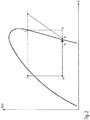
- FIG. 2 shows a diagram in which the enthalpy of a refrigerant is plotted on the abscissa and the ordinate logarithmically the pressure of this refrigerant, which occurs at the heat release condensation occurs.
- the numbers 1, 2, 3, 4a, 4b and 4c denote different states of the refrigerant (see. Fig. 1 ).
- the reference numeral 1 represents the state of the compressed, heated refrigerant, that is, the state of the refrigerant at the inlet 21 of the refrigerant / heating heat exchanger device 14.
- the refrigerant In the desuperheater 15, the refrigerant is isobarically cooled, which is the state 2 at the branching point 23 equivalent.
- the condenser 16 the refrigerant 15 is condensed and cooled further isobar.
- State 3 thus corresponds to the state of the refrigerant at the refrigerant outlet 22 of the refrigerant / heating heat exchanger device 14.
- Condition 2 refrigerant is depressurized via the second expansion element 26 to a state 4a.
- Refrigerant of state 3 is expanded via the third expansion element 29 to a state 4b.
- Refrigerant of the two states 4a, 4b mixes at the junction 30 to refrigerant of the state 4c.
- Refrigerant of the state 4c mixes with the coming of the evaporator 24 refrigerant to a state 4e in which it enters the collector 25.
- FIG. 3 shows the state points in the event that the refrigerant requires a supercritical cooling, as can be for example in the refrigerant carbon dioxide.
- the refrigerant in the first part of the refrigerant / heating heat exchanger means is cooled down to point 2 so far that when it expands to the point 4a either sufficient overheating is present or the point 4a lies at least to the right of the point 4c.
- the further cooling to point 3 takes place in the second part of the refrigerant / heating heat exchanger device on a supercritical isobar.
- the expansion elements 26, 29 are controlled in such a way that even at low ambient temperatures a sufficiently high heat output results with the highest possible overall efficiency.
- a first control strategy allows so much refrigerant through that the refrigerant compressor can condense with the highest possible rotational speed and thus also high power.
- FIG. 4 shows an embodiment in which instead of adjustable expansion elements 26, 29 non-controllable throttles or each orifice valve are provided.
- a shut-off valve 31 is arranged here between the junction 30 and the inlet 27 of the collector 25. Incidentally, the arrangement corresponds to the FIG. 3 the the FIG. 1 ,
- FIG. 5 shows an embodiment in which, unlike FIG. 1 the refrigerant path between the branch point 28 and the junction 30 is omitted. It is therefore not a third expansion element provided, but only the second expansion element 26.
- the state 4a of the refrigerant after the second expansion element 26 can be controlled here by controlling the heating circuit 17 by flowing liquid volume flow, ie by controlling the speed of the water pump 18.
- the expansion member 26 By controlling the expansion member 26, the mass flow of the additional refrigerant for the refrigerant compressor and thus the maximum possible speed of the compressor is controlled.
Landscapes
- Engineering & Computer Science (AREA)
- Physics & Mathematics (AREA)
- Thermal Sciences (AREA)
- Mechanical Engineering (AREA)
- General Engineering & Computer Science (AREA)
- Air-Conditioning For Vehicles (AREA)
- Compression-Type Refrigeration Machines With Reversible Cycles (AREA)
Claims (23)
- Procédé permettant de faire fonctionner un circuit de fluide de refroidissement (10) en tant que pompe à chaleur, selon lequel :• un fluide de refroidissement est comprimé au moyen d'un compresseur et est pompé au travers d'un dispositif échangeur de chaleur (14),• le fluide de refroidissement provenant du dispositif échangeur de chaleur (14) et détendu dans au moins un premier organe de détente (23'),• le fluide de refroidissement détendu par le premier organe de détente (23') passe au travers d'au moins un évaporateur (24) pour être transféré vers une entrée d'aspiration (12) du compresseur (11),
au niveau d'un point de dérivation (23) du dispositif échangeur de chaleur (14) situé entre l'entrée (21) du fluide de refroidissement et la sortie (22) du fluide de refroidissement dans ce dispositif échangeur de chaleur (14), du fluide de refroidissement est dérivé et transféré en direction de l'entrée d'aspiration (12) en passant dans un second organe de détente (26), ce en contournant :- un segment (16) du dispositif échangeur de chaleur (14) situé en aval de la dérivation (23) du fluide de refroidissement,- le premier organe de détente (23'), et- le compresseur (24),caractérisé en ce que• le dispositif échangeur de chaleur (14) est un dispositif échangeur de chaleur fluide de refroidissement/chauffage,• la chaleur dissipée par le fluide de refroidissement dans le dispositif échangeur de chaleur (14) fluide de refroidissement/chauffage étant utilisé pour chauffer l'habitacle d'un véhicule. - Procédé conforme à la revendication 1,
caractérisé en ce que
le fluide de refroidissement est refroidi entre son entrée (21) et le point de dérivation (23). - Procédé conforme à la revendication 2,
caractérisé en ce que
le fluide de refroidissement est encore refroidi entre le point de dérivation (23) et sa sortie (22) de sorte qu'il se condense. - Procédé conforme à l'une des revendications 1 à 3,
caractérisé en ce que
le fluide de refroidissement est encore refroidi dans un état surcritique entre le point de dérivation (23) et sa sortie (22). - Procédé conforme à l'une des revendications 1 à 4,
caractérisé en ce que
le circuit de fluide de refroidissement (10) est couplé thermiquement par l'intermédiaire du dispositif échangeur de chaleur (14) fluide de refroidissement/chauffage avec un circuit de chauffage (17) parcouru par un liquide, le dispositif échangeur de chaleur fluide de refroidissement/chauffage étant un dispositif échangeur de chaleur fluide de refroidissement/liquide (14). - Procédé conforme à la revendication 5,
caractérisé en ce que
le circuit de chauffage (17) comporte une pompe à liquide (18) dont la puissance de refoulement peut être réglée. - Procédé conforme à l'une des revendications 1 à 4,
caractérisé en ce que
le dispositif échangeur de chaleur fluide (14) de refroidissement/chauffage est un dispositif échangeur de chaleur fluide de refroidissement/air qui délivre directement la chaleur à un flux d'air à chauffer. - Procédé conforme à la revendication 7,
caractérisé en ce que
les deux parties du dispositif échangeur de chaleur fluide de refroidissement/air sont montées en série côté air, et de préférence la première partie est parcourue par l'air après la seconde partie. - Procédé conforme à l'une des revendications 1 à 8,
caractérisé en ce qu'
après la sortie du fluide de refroidissement (22) du dispositif échangeur de chaleur fluide de refroidissement/chauffage (14), du fluide de refroidissement est dérivé et transféré vers l'entrée d'aspiration (11) par l'intermédiaire d'un troisième organe de détente (29). - Procédé conforme à l'une quelconque des revendications 1 à 9,
caractérisé en ce que
le fluide de refroidissement provenant du compresseur (24) est transféré vers l'entrée d'aspiration (12) en passant dans un collecteur (25). - Procédé conforme à la revendication 10,
caractérisé en ce que
le fluide de refroidissement provenant du second organe de détente (26) circule vers l'entrée d'aspiration (12) en passant dans le collecteur (25). - Procédé conforme à l'une des revendications précédentes,
caractérisé en ce que
le fluide de refroidissement provenant du troisième organe de détente (29) circule vers l'entrée d'aspiration en passant dans le collecteur (25). - Procédé conforme à l'une des revendications précédentes,
caractérisé en ce que
la densité du fluide de refroidissement à l'entrée d'aspiration (12) du compresseur (11) et/ou le débit massique du fluide de refroidissement à l'entrée d'aspiration (12) est(sont) réglé(es) par commande :- du second organe de détente (26) et/ou- du troisième organe de détente (29) et/ou- de la vitesse de rotation du compresseur (11). - Procédé conforme à l'une des revendications 7 à 13,
caractérisé en ce qu'
au niveau ou à l'avant de l'entrée (27) du fluide de refroidissement dans le collecteur (25),- la pression du fluide de refroidissement est mesurée au moyen d'un capteur de pression, et/ou- la température du fluide de refroidissement est mesurée au moyen d'un capteur de température et par suite, la densité du fluide de refroidissement est déterminée. - Procédé conforme à la revendication 14,
caractérisé en ce que
le second organe de détente et/ou le troisième organe de détente (26, 29) est(sont) commandé(s) ou régulé(s) en fonction de la pression et/ou de la température du fluide de refroidissement. - Procédé conforme à l'une des revendications précédentes,
caractérisé en ce que
la densité du fluide de refroidissement à l'entrée de l'organe de détente (26) est régulée par la vitesse de rotation de la pompe à eau (18). - Circuit de fluide de refroidissement pouvant fonctionner en tant que pompe à chaleur comprenant :- un compresseur (11),- un dispositif échangeur de chaleur (14) monté en aval du compresseur dans la direction de circulation du fluide de refroidissement, qui comporte une entrée du fluide du refroidissement (21) en liaison fluidique avec le côté pression (13) du compresseur (11) et une sortie du fluide de refroidissement (22),- au moins un premier organe de détente (23') en liaison fluidique avec la sortie (22) du fluide de refroidissement,- au moins un évaporateur (24) monté en aval du premier organe de détente dans la direction de circulation du fluide de refroidissement, et à partir duquel le fluide de refroidissement circule vers l'entrée d'aspiration (12) du compresseur (11),- le dispositif échangeur de chaleur (14) comprenant, au niveau d'un point situé entre l'entrée du fluide de refroidissement (21) et la sortie du fluide de refroidissement (22), une dérivation de ce fluide de refroidissement (23) par laquelle le fluide de refroidissement circule vers le côté d'aspiration (12) du compresseur en passant par un second organe de détente (26) et en contournant :- un segment (16) du dispositif échangeur de chaleur (14) situé en aval de la dérivation (23) du fluide de refroidissement,- le premier organe de détente (23'), et- l'évaporateur (24),caractérisé en ce que
le dispositif échangeur de chaleur (14) est un dispositif échangeur de chaleur fluide de refroidissement/liquide (14), et
le circuit de fluide de refroidissement est couplé thermiquement par l'intermédiaire du dispositif échangeur de chaleur fluide de refroidissement/liquide (14) avec un circuit de chauffage (17) traversé par un liquide. - Circuit de fluide de refroidissement conforme à la revendication 17,
caractérisé en ce qu'
il est prévu un collecteur (25) qui est monté entre l'évaporateur (24) et l'entrée d'aspiration (12) ou entre la dérivation du fluide de refroidissement (23) et l'entrée d'aspiration (12). - Circuit de fluide de refroidissement conforme à la revendication 18,
caractérisé en ce qu'
un second organe de détente (26) est monté entre la dérivation du fluide de refroidissement (23) et le collecteur (25). - Circuit de fluide de refroidissement conforme à l'une des revendications 18 et 19,
caractérisé en ce que
la sortie du fluide de refroidissement (22) du dispositif échangeur de chaleur fluide de refroidissement/liquide (14) est reliée au collecteur (25) par l'intermédiaire d'un troisième organe de détente (29). - Circuit de fluide de refroidissement conforme à la revendication 20,
caractérisé en ce que
le second organe de détente et/ou le troisième organe de détente est(sont) constitué(s) par un(des) organe(s) de détente (26, 29) réglable(s). - Circuit de fluide de refroidissement conforme à la revendication 20,
caractérisé en ce que
le second organe de détente et/ou le troisième organe de détente (26, 29) est(sont) constitué(s) par un étranglement ayant une section d'écoulement fixe. - Circuit de fluide de refroidissement conforme à l'une des revendications 17 à 22,
caractérisé en ce que
le circuit de chauffage (17) comporte une pompe (18) dont la puissance de refoulement est réglable.
Applications Claiming Priority (2)
| Application Number | Priority Date | Filing Date | Title |
|---|---|---|---|
| DE102012222594.3A DE102012222594B4 (de) | 2012-12-10 | 2012-12-10 | Verfahren zum Betreiben eines Kältemittelkreislaufs als Wärmepumpe sowie als Wärmepumpe betreibbarer Kältemittelkreislauf |
| PCT/EP2013/073201 WO2014090484A1 (fr) | 2012-12-10 | 2013-11-07 | Procédé servant à faire fonctionner un circuit de fluide de refroidissement comme une pompe à chaleur, et circuit de fluide de refroidissement pouvant fonctionner comme une pompe à chaleur |
Publications (2)
| Publication Number | Publication Date |
|---|---|
| EP2928710A1 EP2928710A1 (fr) | 2015-10-14 |
| EP2928710B1 true EP2928710B1 (fr) | 2018-08-08 |
Family
ID=49546418
Family Applications (1)
| Application Number | Title | Priority Date | Filing Date |
|---|---|---|---|
| EP13786499.7A Active EP2928710B1 (fr) | 2012-12-10 | 2013-11-07 | Procédé servant à faire fonctionner un circuit de fluide de refroidissement comme une pompe à chaleur |
Country Status (5)
| Country | Link |
|---|---|
| US (1) | US9625188B2 (fr) |
| EP (1) | EP2928710B1 (fr) |
| CN (1) | CN104661841B (fr) |
| DE (1) | DE102012222594B4 (fr) |
| WO (1) | WO2014090484A1 (fr) |
Families Citing this family (10)
| Publication number | Priority date | Publication date | Assignee | Title |
|---|---|---|---|---|
| US10272744B2 (en) * | 2015-09-03 | 2019-04-30 | Ford Global Technologies, Llc | Vehicle HVAC system with auxiliary coolant loop for heating and cooling vehicle interior |
| CN106322828B (zh) * | 2016-04-17 | 2020-05-01 | 李华玉 | 第二类热驱动压缩式热泵 |
| DE102016213619A1 (de) | 2016-07-25 | 2018-01-25 | Bayerische Motoren Werke Aktiengesellschaft | Verfahren zum betrieb eines klimasystems sowie klimasystem |
| FR3055249B1 (fr) * | 2016-08-30 | 2018-09-14 | Valeo Systemes Thermiques | Circuit de climatisation inversible indirect de vehicule automobile et procede de fonctionnement correspondant |
| US11175082B2 (en) * | 2017-04-27 | 2021-11-16 | Mitsubishi Electric Corporation | Refrigeration cycle apparatus with heat storage for use during defrost |
| KR20190120936A (ko) * | 2018-04-17 | 2019-10-25 | 한온시스템 주식회사 | 차량의 열관리 시스템 |
| DE102018214211A1 (de) * | 2018-08-22 | 2020-02-27 | Volkswagen Aktiengesellschaft | Einrichtung und Verfahren zum Temperieren eines elektrischen Energiespeichers für ein Kraftfahrzeug |
| DE102019120229A1 (de) | 2019-07-26 | 2021-01-28 | Bayerische Motoren Werke Aktiengesellschaft | Wärmemanagementsystem für ein Kraftfahrzeug, Verfahren zum Wärmemanagement eines Kraftfahrzeugs und Kraftfahrzeug mit einem Wärmemanagementsystem |
| DE102020117701A1 (de) | 2020-07-06 | 2022-01-13 | Audi Aktiengesellschaft | Kälteanlage mit Wärmepumpenfunktion basierend auf einem erweiterbaren Basissystem und Kraftfahrzeug mit einer solchen Kälteanlage |
| DE102020128840B4 (de) | 2020-11-03 | 2023-08-31 | Bayerische Motoren Werke Aktiengesellschaft | Klimasystem, Verfahren zum Steuern eines solchen und Kraftfahrzeug |
Family Cites Families (14)
| Publication number | Priority date | Publication date | Assignee | Title |
|---|---|---|---|---|
| US4163369A (en) * | 1978-05-11 | 1979-08-07 | Charles Owen | Air-to-air heat pump |
| US4474018A (en) * | 1982-05-06 | 1984-10-02 | Arthur D. Little, Inc. | Heat pump system for production of domestic hot water |
| JP3794121B2 (ja) * | 1997-02-28 | 2006-07-05 | 株式会社デンソー | 車両用空調装置 |
| EP1148307B1 (fr) * | 2000-04-19 | 2004-03-17 | Denso Corporation | Chauffe-eau avec pompe à chaleur |
| US6293108B1 (en) | 2000-06-30 | 2001-09-25 | Vortex Aircon | Regenerative refrigeration system with mixed refrigerants |
| US6536221B2 (en) * | 2001-01-16 | 2003-03-25 | Norbert L. James | Air conditioning heat recovery arrangement |
| DE10207128A1 (de) | 2002-02-20 | 2003-08-21 | Zexel Valeo Compressor Europe | Fahrzeugklimaanlage, insbesondere CO2-Klimaanlage |
| JP2004182204A (ja) * | 2002-12-06 | 2004-07-02 | Mitsubishi Heavy Ind Ltd | 車両用空調装置及び車両用空調方法 |
| BRPI0508190B1 (pt) | 2004-02-26 | 2019-12-24 | Ventech Llc | aparelho de aquecimento e sistema de aquecimento |
| DE102007034821A1 (de) | 2007-07-26 | 2009-01-29 | Ford Global Technologies, LLC, Dearborn | Klimaanlage für ein Kraftfahrzeug sowie Verfahren zu deren Betrieb |
| CN100535550C (zh) * | 2008-07-29 | 2009-09-02 | 广州精益汽车空调有限公司 | 一种汽车热泵空调系统 |
| US9593872B2 (en) * | 2009-10-27 | 2017-03-14 | Mitsubishi Electric Corporation | Heat pump |
| JP5423528B2 (ja) * | 2010-03-29 | 2014-02-19 | 株式会社日本自動車部品総合研究所 | ヒートポンプサイクル |
| JP2012132586A (ja) * | 2010-12-20 | 2012-07-12 | Calsonic Kansei Corp | 冷凍サイクル装置 |
-
2012
- 2012-12-10 DE DE102012222594.3A patent/DE102012222594B4/de not_active Expired - Fee Related
-
2013
- 2013-11-07 EP EP13786499.7A patent/EP2928710B1/fr active Active
- 2013-11-07 WO PCT/EP2013/073201 patent/WO2014090484A1/fr active Application Filing
- 2013-11-07 CN CN201380050178.0A patent/CN104661841B/zh active Active
-
2015
- 2015-06-09 US US14/734,535 patent/US9625188B2/en active Active
Non-Patent Citations (1)
| Title |
|---|
| None * |
Also Published As
| Publication number | Publication date |
|---|---|
| CN104661841A (zh) | 2015-05-27 |
| US20150276281A1 (en) | 2015-10-01 |
| EP2928710A1 (fr) | 2015-10-14 |
| DE102012222594A1 (de) | 2014-06-12 |
| CN104661841B (zh) | 2017-08-04 |
| WO2014090484A1 (fr) | 2014-06-19 |
| US9625188B2 (en) | 2017-04-18 |
| DE102012222594B4 (de) | 2018-05-17 |
Similar Documents
| Publication | Publication Date | Title |
|---|---|---|
| EP2928710B1 (fr) | Procédé servant à faire fonctionner un circuit de fluide de refroidissement comme une pompe à chaleur | |
| EP3444542B1 (fr) | Système de circulation pour un véhicule et procédé associé | |
| EP3697635B1 (fr) | Procédé servant à faire fonctionner un circuit frigorifique ainsi qu'une installation de réfrigération de véhicule | |
| EP1264715B2 (fr) | Système de refroidissement d'un véhicule pour un dispositif d'augmentation de la température et méthode pour le refroidissement du dispositif d'augmentation de la température | |
| DE102012111672B4 (de) | Kältemittelkreislauf einer Klimaanlage mit Wärmepumpen- und Nachheizfunktionalität | |
| EP1526974B1 (fr) | Installation de climatisation pour vehicule automobile | |
| DE102015122721B4 (de) | Klimatisierungssystem eines Kraftfahrzeugs und Verfahren zum Betreiben des Klimatisierungssystems | |
| DE102014115530B4 (de) | Verfahren zum Regulieren der Kühlmitteltemperatur eines HVAC-Wärmepumpen-Systemfelds | |
| DE102010051976B4 (de) | Klimaanlage für ein Kraftfahrzeug | |
| DE102018126933A1 (de) | Dampfeinspritzungswärmepumpe und Steuerverfahren | |
| DE102020111505B4 (de) | Wärmepumpenanordnung für batteriebetriebene Fahrzeuge und Verfahren zum Betreiben einer Wärmepumpenanordnung | |
| DE102014112343A1 (de) | Fahrzeugklimaanlagensystem mit einem schaltenden Wärmetauscher | |
| DE112013003304T5 (de) | Fahrzeugklimaanlageneinheit | |
| DE102013206626A1 (de) | Wärmepumpenanlage sowie Verfahren zur Klimatisierung eines Fahrzeuges | |
| DE102020117471B4 (de) | Wärmepumpenanordnung mit indirekter Batterieerwärmung für batteriebetriebene Kraftfahrzeuge und Verfahren zum Betreiben einer Wärmepumpenanordnung | |
| WO2014166596A1 (fr) | Systeme de climatisation pour véhicule | |
| WO2012159814A1 (fr) | Circuit de pompe à chaleur pour véhicules | |
| WO2019214927A1 (fr) | Système de refroidissement d'un véhicule, muni d'un circuit de fluide réfrigérant présentant une fonction de pompe à chaleur | |
| EP1462281B1 (fr) | Appareil de climatisation avec plusieurs évaporateurs pour véhicule à moteur | |
| DE112015000750T5 (de) | Kältefluidkreislauf zur thermischen Behandlung eines Kraftfahrzeugs | |
| DE102013219146A1 (de) | Fahrzeug-wärmepumpensystem und -steuerverfahren | |
| WO2014154326A1 (fr) | Système de climatisation pour véhicule | |
| DE102017213973A1 (de) | Verfahren zum Betreiben einer Kälteanlage eines Fahrzeugs mit einem eine Kühl- und Heizfunktion aufweisenden Kältemittelkreislauf | |
| WO2023280507A1 (fr) | Circuit de réfrigération ainsi que système de gestion thermique et véhicule motorisé comportant un circuit de réfrigération de ce type | |
| DE112021004952T5 (de) | Fahrzeugklimaanlage |
Legal Events
| Date | Code | Title | Description |
|---|---|---|---|
| PUAI | Public reference made under article 153(3) epc to a published international application that has entered the european phase |
Free format text: ORIGINAL CODE: 0009012 |
|
| 17P | Request for examination filed |
Effective date: 20150429 |
|
| AK | Designated contracting states |
Kind code of ref document: A1 Designated state(s): AL AT BE BG CH CY CZ DE DK EE ES FI FR GB GR HR HU IE IS IT LI LT LU LV MC MK MT NL NO PL PT RO RS SE SI SK SM TR |
|
| AX | Request for extension of the european patent |
Extension state: BA ME |
|
| DAX | Request for extension of the european patent (deleted) | ||
| 17Q | First examination report despatched |
Effective date: 20171220 |
|
| GRAP | Despatch of communication of intention to grant a patent |
Free format text: ORIGINAL CODE: EPIDOSNIGR1 |
|
| RIC1 | Information provided on ipc code assigned before grant |
Ipc: F25B 30/02 20060101ALI20180305BHEP Ipc: B60H 1/00 20060101AFI20180305BHEP |
|
| INTG | Intention to grant announced |
Effective date: 20180321 |
|
| GRAS | Grant fee paid |
Free format text: ORIGINAL CODE: EPIDOSNIGR3 |
|
| GRAA | (expected) grant |
Free format text: ORIGINAL CODE: 0009210 |
|
| AK | Designated contracting states |
Kind code of ref document: B1 Designated state(s): AL AT BE BG CH CY CZ DE DK EE ES FI FR GB GR HR HU IE IS IT LI LT LU LV MC MK MT NL NO PL PT RO RS SE SI SK SM TR |
|
| REG | Reference to a national code |
Ref country code: GB Ref legal event code: FG4D Free format text: NOT ENGLISH |
|
| REG | Reference to a national code |
Ref country code: CH Ref legal event code: EP Ref country code: AT Ref legal event code: REF Ref document number: 1026576 Country of ref document: AT Kind code of ref document: T Effective date: 20180815 |
|
| REG | Reference to a national code |
Ref country code: IE Ref legal event code: FG4D Free format text: LANGUAGE OF EP DOCUMENT: GERMAN |
|
| REG | Reference to a national code |
Ref country code: DE Ref legal event code: R096 Ref document number: 502013010816 Country of ref document: DE |
|
| REG | Reference to a national code |
Ref country code: NL Ref legal event code: MP Effective date: 20180808 |
|
| REG | Reference to a national code |
Ref country code: LT Ref legal event code: MG4D |
|
| PG25 | Lapsed in a contracting state [announced via postgrant information from national office to epo] |
Ref country code: RS Free format text: LAPSE BECAUSE OF FAILURE TO SUBMIT A TRANSLATION OF THE DESCRIPTION OR TO PAY THE FEE WITHIN THE PRESCRIBED TIME-LIMIT Effective date: 20180808 Ref country code: IS Free format text: LAPSE BECAUSE OF FAILURE TO SUBMIT A TRANSLATION OF THE DESCRIPTION OR TO PAY THE FEE WITHIN THE PRESCRIBED TIME-LIMIT Effective date: 20181208 Ref country code: LT Free format text: LAPSE BECAUSE OF FAILURE TO SUBMIT A TRANSLATION OF THE DESCRIPTION OR TO PAY THE FEE WITHIN THE PRESCRIBED TIME-LIMIT Effective date: 20180808 Ref country code: PL Free format text: LAPSE BECAUSE OF FAILURE TO SUBMIT A TRANSLATION OF THE DESCRIPTION OR TO PAY THE FEE WITHIN THE PRESCRIBED TIME-LIMIT Effective date: 20180808 Ref country code: NL Free format text: LAPSE BECAUSE OF FAILURE TO SUBMIT A TRANSLATION OF THE DESCRIPTION OR TO PAY THE FEE WITHIN THE PRESCRIBED TIME-LIMIT Effective date: 20180808 Ref country code: GR Free format text: LAPSE BECAUSE OF FAILURE TO SUBMIT A TRANSLATION OF THE DESCRIPTION OR TO PAY THE FEE WITHIN THE PRESCRIBED TIME-LIMIT Effective date: 20181109 Ref country code: NO Free format text: LAPSE BECAUSE OF FAILURE TO SUBMIT A TRANSLATION OF THE DESCRIPTION OR TO PAY THE FEE WITHIN THE PRESCRIBED TIME-LIMIT Effective date: 20181108 Ref country code: BG Free format text: LAPSE BECAUSE OF FAILURE TO SUBMIT A TRANSLATION OF THE DESCRIPTION OR TO PAY THE FEE WITHIN THE PRESCRIBED TIME-LIMIT Effective date: 20181108 Ref country code: FI Free format text: LAPSE BECAUSE OF FAILURE TO SUBMIT A TRANSLATION OF THE DESCRIPTION OR TO PAY THE FEE WITHIN THE PRESCRIBED TIME-LIMIT Effective date: 20180808 Ref country code: SE Free format text: LAPSE BECAUSE OF FAILURE TO SUBMIT A TRANSLATION OF THE DESCRIPTION OR TO PAY THE FEE WITHIN THE PRESCRIBED TIME-LIMIT Effective date: 20180808 |
|
| PG25 | Lapsed in a contracting state [announced via postgrant information from national office to epo] |
Ref country code: LV Free format text: LAPSE BECAUSE OF FAILURE TO SUBMIT A TRANSLATION OF THE DESCRIPTION OR TO PAY THE FEE WITHIN THE PRESCRIBED TIME-LIMIT Effective date: 20180808 Ref country code: AL Free format text: LAPSE BECAUSE OF FAILURE TO SUBMIT A TRANSLATION OF THE DESCRIPTION OR TO PAY THE FEE WITHIN THE PRESCRIBED TIME-LIMIT Effective date: 20180808 Ref country code: HR Free format text: LAPSE BECAUSE OF FAILURE TO SUBMIT A TRANSLATION OF THE DESCRIPTION OR TO PAY THE FEE WITHIN THE PRESCRIBED TIME-LIMIT Effective date: 20180808 |
|
| PG25 | Lapsed in a contracting state [announced via postgrant information from national office to epo] |
Ref country code: EE Free format text: LAPSE BECAUSE OF FAILURE TO SUBMIT A TRANSLATION OF THE DESCRIPTION OR TO PAY THE FEE WITHIN THE PRESCRIBED TIME-LIMIT Effective date: 20180808 Ref country code: ES Free format text: LAPSE BECAUSE OF FAILURE TO SUBMIT A TRANSLATION OF THE DESCRIPTION OR TO PAY THE FEE WITHIN THE PRESCRIBED TIME-LIMIT Effective date: 20180808 Ref country code: CZ Free format text: LAPSE BECAUSE OF FAILURE TO SUBMIT A TRANSLATION OF THE DESCRIPTION OR TO PAY THE FEE WITHIN THE PRESCRIBED TIME-LIMIT Effective date: 20180808 Ref country code: RO Free format text: LAPSE BECAUSE OF FAILURE TO SUBMIT A TRANSLATION OF THE DESCRIPTION OR TO PAY THE FEE WITHIN THE PRESCRIBED TIME-LIMIT Effective date: 20180808 |
|
| REG | Reference to a national code |
Ref country code: DE Ref legal event code: R097 Ref document number: 502013010816 Country of ref document: DE |
|
| PG25 | Lapsed in a contracting state [announced via postgrant information from national office to epo] |
Ref country code: SM Free format text: LAPSE BECAUSE OF FAILURE TO SUBMIT A TRANSLATION OF THE DESCRIPTION OR TO PAY THE FEE WITHIN THE PRESCRIBED TIME-LIMIT Effective date: 20180808 Ref country code: DK Free format text: LAPSE BECAUSE OF FAILURE TO SUBMIT A TRANSLATION OF THE DESCRIPTION OR TO PAY THE FEE WITHIN THE PRESCRIBED TIME-LIMIT Effective date: 20180808 Ref country code: SK Free format text: LAPSE BECAUSE OF FAILURE TO SUBMIT A TRANSLATION OF THE DESCRIPTION OR TO PAY THE FEE WITHIN THE PRESCRIBED TIME-LIMIT Effective date: 20180808 |
|
| PLBE | No opposition filed within time limit |
Free format text: ORIGINAL CODE: 0009261 |
|
| STAA | Information on the status of an ep patent application or granted ep patent |
Free format text: STATUS: NO OPPOSITION FILED WITHIN TIME LIMIT |
|
| REG | Reference to a national code |
Ref country code: CH Ref legal event code: PL |
|
| 26N | No opposition filed |
Effective date: 20190509 |
|
| PG25 | Lapsed in a contracting state [announced via postgrant information from national office to epo] |
Ref country code: LU Free format text: LAPSE BECAUSE OF NON-PAYMENT OF DUE FEES Effective date: 20181107 Ref country code: MC Free format text: LAPSE BECAUSE OF FAILURE TO SUBMIT A TRANSLATION OF THE DESCRIPTION OR TO PAY THE FEE WITHIN THE PRESCRIBED TIME-LIMIT Effective date: 20180808 |
|
| REG | Reference to a national code |
Ref country code: BE Ref legal event code: MM Effective date: 20181130 |
|
| REG | Reference to a national code |
Ref country code: IE Ref legal event code: MM4A |
|
| PG25 | Lapsed in a contracting state [announced via postgrant information from national office to epo] |
Ref country code: LI Free format text: LAPSE BECAUSE OF NON-PAYMENT OF DUE FEES Effective date: 20181130 Ref country code: SI Free format text: LAPSE BECAUSE OF FAILURE TO SUBMIT A TRANSLATION OF THE DESCRIPTION OR TO PAY THE FEE WITHIN THE PRESCRIBED TIME-LIMIT Effective date: 20180808 Ref country code: CH Free format text: LAPSE BECAUSE OF NON-PAYMENT OF DUE FEES Effective date: 20181130 |
|
| PG25 | Lapsed in a contracting state [announced via postgrant information from national office to epo] |
Ref country code: IE Free format text: LAPSE BECAUSE OF NON-PAYMENT OF DUE FEES Effective date: 20181107 |
|
| PG25 | Lapsed in a contracting state [announced via postgrant information from national office to epo] |
Ref country code: BE Free format text: LAPSE BECAUSE OF NON-PAYMENT OF DUE FEES Effective date: 20181130 |
|
| REG | Reference to a national code |
Ref country code: AT Ref legal event code: MM01 Ref document number: 1026576 Country of ref document: AT Kind code of ref document: T Effective date: 20181107 |
|
| PG25 | Lapsed in a contracting state [announced via postgrant information from national office to epo] |
Ref country code: AT Free format text: LAPSE BECAUSE OF NON-PAYMENT OF DUE FEES Effective date: 20181107 Ref country code: MT Free format text: LAPSE BECAUSE OF FAILURE TO SUBMIT A TRANSLATION OF THE DESCRIPTION OR TO PAY THE FEE WITHIN THE PRESCRIBED TIME-LIMIT Effective date: 20180808 |
|
| PG25 | Lapsed in a contracting state [announced via postgrant information from national office to epo] |
Ref country code: TR Free format text: LAPSE BECAUSE OF FAILURE TO SUBMIT A TRANSLATION OF THE DESCRIPTION OR TO PAY THE FEE WITHIN THE PRESCRIBED TIME-LIMIT Effective date: 20180808 |
|
| PG25 | Lapsed in a contracting state [announced via postgrant information from national office to epo] |
Ref country code: PT Free format text: LAPSE BECAUSE OF FAILURE TO SUBMIT A TRANSLATION OF THE DESCRIPTION OR TO PAY THE FEE WITHIN THE PRESCRIBED TIME-LIMIT Effective date: 20180808 |
|
| PG25 | Lapsed in a contracting state [announced via postgrant information from national office to epo] |
Ref country code: CY Free format text: LAPSE BECAUSE OF FAILURE TO SUBMIT A TRANSLATION OF THE DESCRIPTION OR TO PAY THE FEE WITHIN THE PRESCRIBED TIME-LIMIT Effective date: 20180808 Ref country code: MK Free format text: LAPSE BECAUSE OF NON-PAYMENT OF DUE FEES Effective date: 20180808 Ref country code: HU Free format text: LAPSE BECAUSE OF FAILURE TO SUBMIT A TRANSLATION OF THE DESCRIPTION OR TO PAY THE FEE WITHIN THE PRESCRIBED TIME-LIMIT; INVALID AB INITIO Effective date: 20131107 |
|
| P01 | Opt-out of the competence of the unified patent court (upc) registered |
Effective date: 20230502 |
|
| PGFP | Annual fee paid to national office [announced via postgrant information from national office to epo] |
Ref country code: GB Payment date: 20231123 Year of fee payment: 11 |
|
| PGFP | Annual fee paid to national office [announced via postgrant information from national office to epo] |
Ref country code: IT Payment date: 20231130 Year of fee payment: 11 Ref country code: FR Payment date: 20231122 Year of fee payment: 11 Ref country code: DE Payment date: 20231113 Year of fee payment: 11 |