EP2928019B1 - Multi-frequency array antenna - Google Patents
Multi-frequency array antenna Download PDFInfo
- Publication number
- EP2928019B1 EP2928019B1 EP13858188.9A EP13858188A EP2928019B1 EP 2928019 B1 EP2928019 B1 EP 2928019B1 EP 13858188 A EP13858188 A EP 13858188A EP 2928019 B1 EP2928019 B1 EP 2928019B1
- Authority
- EP
- European Patent Office
- Prior art keywords
- frequency
- low
- frequency radiation
- units
- radiation units
- Prior art date
- Legal status (The legal status is an assumption and is not a legal conclusion. Google has not performed a legal analysis and makes no representation as to the accuracy of the status listed.)
- Active
Links
Images

Classifications
-
- H—ELECTRICITY
- H01—ELECTRIC ELEMENTS
- H01Q—ANTENNAS, i.e. RADIO AERIALS
- H01Q5/00—Arrangements for simultaneous operation of antennas on two or more different wavebands, e.g. dual-band or multi-band arrangements
- H01Q5/20—Arrangements for simultaneous operation of antennas on two or more different wavebands, e.g. dual-band or multi-band arrangements characterised by the operating wavebands
-
- H—ELECTRICITY
- H01—ELECTRIC ELEMENTS
- H01Q—ANTENNAS, i.e. RADIO AERIALS
- H01Q1/00—Details of, or arrangements associated with, antennas
- H01Q1/12—Supports; Mounting means
- H01Q1/22—Supports; Mounting means by structural association with other equipment or articles
- H01Q1/24—Supports; Mounting means by structural association with other equipment or articles with receiving set
- H01Q1/241—Supports; Mounting means by structural association with other equipment or articles with receiving set used in mobile communications, e.g. GSM
- H01Q1/246—Supports; Mounting means by structural association with other equipment or articles with receiving set used in mobile communications, e.g. GSM specially adapted for base stations
-
- H—ELECTRICITY
- H01—ELECTRIC ELEMENTS
- H01Q—ANTENNAS, i.e. RADIO AERIALS
- H01Q19/00—Combinations of primary active antenna elements and units with secondary devices, e.g. with quasi-optical devices, for giving the antenna a desired directional characteristic
- H01Q19/10—Combinations of primary active antenna elements and units with secondary devices, e.g. with quasi-optical devices, for giving the antenna a desired directional characteristic using reflecting surfaces
-
- H—ELECTRICITY
- H01—ELECTRIC ELEMENTS
- H01Q—ANTENNAS, i.e. RADIO AERIALS
- H01Q19/00—Combinations of primary active antenna elements and units with secondary devices, e.g. with quasi-optical devices, for giving the antenna a desired directional characteristic
- H01Q19/10—Combinations of primary active antenna elements and units with secondary devices, e.g. with quasi-optical devices, for giving the antenna a desired directional characteristic using reflecting surfaces
- H01Q19/106—Combinations of primary active antenna elements and units with secondary devices, e.g. with quasi-optical devices, for giving the antenna a desired directional characteristic using reflecting surfaces using two or more intersecting plane surfaces, e.g. corner reflector antennas
-
- H—ELECTRICITY
- H01—ELECTRIC ELEMENTS
- H01Q—ANTENNAS, i.e. RADIO AERIALS
- H01Q21/00—Antenna arrays or systems
- H01Q21/24—Combinations of antenna units polarised in different directions for transmitting or receiving circularly and elliptically polarised waves or waves linearly polarised in any direction
- H01Q21/26—Turnstile or like antennas comprising arrangements of three or more elongated elements disposed radially and symmetrically in a horizontal plane about a common centre
-
- H—ELECTRICITY
- H01—ELECTRIC ELEMENTS
- H01Q—ANTENNAS, i.e. RADIO AERIALS
- H01Q5/00—Arrangements for simultaneous operation of antennas on two or more different wavebands, e.g. dual-band or multi-band arrangements
- H01Q5/40—Imbricated or interleaved structures; Combined or electromagnetically coupled arrangements, e.g. comprising two or more non-connected fed radiating elements
-
- H—ELECTRICITY
- H01—ELECTRIC ELEMENTS
- H01Q—ANTENNAS, i.e. RADIO AERIALS
- H01Q5/00—Arrangements for simultaneous operation of antennas on two or more different wavebands, e.g. dual-band or multi-band arrangements
- H01Q5/40—Imbricated or interleaved structures; Combined or electromagnetically coupled arrangements, e.g. comprising two or more non-connected fed radiating elements
- H01Q5/42—Imbricated or interleaved structures; Combined or electromagnetically coupled arrangements, e.g. comprising two or more non-connected fed radiating elements using two or more imbricated arrays
-
- H—ELECTRICITY
- H01—ELECTRIC ELEMENTS
- H01Q—ANTENNAS, i.e. RADIO AERIALS
- H01Q9/00—Electrically-short antennas having dimensions not more than twice the operating wavelength and consisting of conductive active radiating elements
- H01Q9/04—Resonant antennas
- H01Q9/16—Resonant antennas with feed intermediate between the extremities of the antenna, e.g. centre-fed dipole
- H01Q9/26—Resonant antennas with feed intermediate between the extremities of the antenna, e.g. centre-fed dipole with folded element or elements, the folded parts being spaced apart a small fraction of operating wavelength
Definitions
- the present invention relates to the field of mobile communication, and in particular to a multi-frequency array antenna applicable for frequency bands of 2G, 3G and 4G.
- the wavelength at the center frequency of the low-frequency band is 337 mm, while the wavelength at the center frequency of the high-frequency band is only 154.6 mm.
- the ratio of the two is 2.17 times. According to the prior art, therefore, the optimal setup is usually that the distance between low-frequency radiation units is 2 times of the distance between high-frequency radiation units.
- the above published patents easily realize a broadband, narrow cross-sectional multi-frequency common base station antenna with 2G/3G coaxial arrangement.
- the principle of implementation is based on the relationship that the center frequency of the working band of low-frequency radiation unit is close to 2 times of the center frequency of the working band of high-frequency radiation unit, the configuration that the low-frequency radiation units are nested with one high-frequency radiation unit is usually employed by simultaneously arranging a high-frequency radiation unit between two low-frequency radiation units. In the end, the distance between two neighboring low-frequency radiation units is 2 times of the distance between two neighboring high-frequency radiators.
- the ratio of wavelengths corresponding to the center frequencies of the low-frequency band and the high-frequency band has reached a relationship greater than 2 times of frequency.
- the working bands of 2G/3G/4G mobile communication systems are: the low-frequency band is 790 - 960 MHz and the high-frequency band is 1700 - 2700 MHz, the wavelength at the center frequency of the low-frequency band is 342 mm, while the wavelength at the center frequency of the high-frequency band is only 136.36 mm.
- the ratio of the two has reached 2.5 times.
- the highest frequency of 2700 MHz is more than 3.4 times of the low-frequency end of 790 MHz. Therefore, the relationship that the distance between low-frequency radiation units is 2 times of the distance between high-frequency units is no longer able to achieve the optimal radiation performance of the high/low frequency array antenna.
- Claim 1 is "a dual-band and dual-polarized antenna, comprising: a reflector, and a high-frequency radiator array and a low-frequency radiator array arranged on the same side of the reflector and comprised of two or more high-frequency radiators and low-frequency radiators, respectively, the high-frequency radiators and low-frequency radiators are coaxially arranged along the axis of the reflector, characterized in that two high-frequency radiators are arranged between neighboring low-frequency radiators, and each low-frequency radiator encases a high-frequency radiator"; in addition, Claim 5 is that "every two neighboring high-frequency radiators are spaced at 106 mm, and every two neighboring low-frequency radiators are spaced at 318 mm.” It can be seen from Claim 1, together with Fig.
- the distance between low-frequency radiators is 3 times of the distance between high-frequency radiators.
- the wavelength at the center frequency of the high-frequency band is 2.5 times of that of the low-frequency band in the existing mobile communication bands.
- such an arraying configuration is merely an improvement, which cannot fundamentally solve the arraying problem of existing dual-broad frequency antennas.
- the distance between high-frequency radiators is set to 106 mm, the distance between low-frequency radiators is 318 mm, the distance between low-frequency units is 1.02 times of the wavelength at the frequency of 960 MHz that is 312.5 mm.
- a distance between low-frequency radiation units that exceeds one times of the wavelength apparently has serious impact on the performance of low-frequency arrays.
- the gating lobe of high level will unavoidably occur in the electrical down-tilting process of the vertical face at the frequency of 960 MHz, leading to deteriorated radiation performance indices thereof.
- Prior art EP2521218A2 discloses (see fig. 4 ) alternating 1:2 and 1:3 ratios between low-frequency and high-frequency units.
- the object of embodiment of the present invention is to overcome the above drawbacks by providing a multi-frequency array antenna, looking for the layout relationship between the neighboring distance of low-frequency radiation units and the neighboring distance of high-frequency radiation units so as to realize the coaxial arraying of low-frequency radiation units and high-frequency radiation units so as to be compatible with signals of current 2G, 3G and 4G mobile communication networks.
- the multi-frequency array antenna as defined in independent claim 1 and according to the embodiment of the present invention comprises a metal reflector, a low-frequency radiation column element that is arranged on the metal reflector and operates in a first frequency band range, and a high-frequency radiation column element operating in a second frequency band range.
- the low-frequency radiation column element comprises several low-frequency radiation units arranged at an equal first distance in the axial direction of a first reference axis
- the high-frequency radiation column element comprises several high-frequency radiation units arranged at an equal second distance in the axial direction of the first reference axis, wherein the first distance is 2.5 times of the second distance, a first one of the low-frequency radiation units is nested with one high-frequency radiation unit locationally corresponding thereto, and separately, a second one of the low-frequency radiation units is axially located between two neighboring high-frequency radiation units adjacent to the second low-frequency radiation unit and is not nested with one of the high-frequency radiation units.
- an optimal setting is obtained by limiting the first distance to be 2.5 times of the second distance, which substantially arranges the low-frequency radiation column element and the high-frequency radiation column element on the same first reference axis, such that the electrical performance of signals in all band ranges is optimized, consequently it can be simultaneously compatible with mobile communication systems in the range of three operating bands of 2G, 3G and 4G.
- signal receiving and transmission can be performed for all of the current mobile communication systems, such as GSM, CDMA and LTE, with one set of multi-frequency array antenna, which solves the difficulty that has not been addressed and has obsesses those skilled in the art for many years.
- the low-frequency radiation column element employs two types of low-frequency radiation units with different structures, it can effectively avoid the phenomenon that their radiation arms are overlapped when projected orthographically to the orthographical projection plane of the metal reflector, thereby minimizing the signal interference between the low-frequency radiation column element and the high-frequency radiation column element and ensuring that the multiple relationship between the above two distances is more reliable.
- the first distance and the second distance are 0.6 - 1.0 times of their frequency band ranges, preferably 0.8 times, it further optimizes the entire arraying effect such that the electrical performance of the multi-frequency array antenna according to the present invention is optimized.
- radiation column elements comprising low-frequency radiation column element and high-frequency radiation column element
- communicating signals which are typically formed by arranging a plurality of radiation units in a single-column matrix on a metal reflector.
- the high-frequency radiation column element is formed by arranging a plurality of high-frequency radiation units at an equal distance in the axial direction of the same reference axis, and for the ease of subsequent description, the distance is defined as the second distance.
- the low-frequency radiation column element is formed by arranging a plurality of low-frequency radiation units at an equal distance in the axial direction of the same reference axis, and similarly, the distance is defined as the second distance, wherein the part of the radiation units for performing signal transmission and receiving is the radiation arm thereof, the radiation arm is usually located at the periphery of a radiation unit and has a variety of known structures. However, they all employ the central symmetric relationship, i.e. they typically consist of two pairs of symmetric radiators in the orthogonal form, each pair of symmetric radiators comprises two of the radiation arms, and radiation arms of common radiation units mostly form a ring shape, including rectangular and circular.
- the radiation arm may also be designed to have a shape of horizontal elongation, and the same pair of symmetric radiators is substantially elongated longitudinally, such that the radiation units after orthogonal configuration appear to be a "cross".
- Radiation units may be printed in 2 dimensions, or may have a 3-D structure.
- the low-frequency radiation column element and high-frequency radiation column element thereof all operate in different frequency band ranges, and the "low-frequency" of the low-frequency radiation column element herein indicates that it is lower than the frequency of the "high-frequency" of the high-frequency radiation column element.
- the low-frequency radiation column element operates in the frequency band range of 790 - 960 MHz, which covers current 2G and 3G mobile communication frequency bands globally, while the high-frequency radiation column element operates in the frequency band range of 1700 - 2700 MHz, which covers current 4G mobile communication frequency bands globally, such as the LTE standard.
- the multi-frequency array antenna according to Example 1 of the present invention arranges a low-frequency radiation column element and a high-frequency radiation column element coaxially along an imaginary first reference axis a on the metal reflector 1, thereby forming a set of dual frequency common antenna.
- the high-frequency radiation column element is formed by 12 high-frequency radiation units (4, 5, 6) arranged sequentially at an equal second distance in the axial direction of the first reference axis a, all of the high-frequency radiation units are arranged on the first reference axis a, and arranged in the position sequence from left to right.
- the second distance between the locationally neighboring high-frequency radiation units 4, 6, 5 is defined as d.
- the low-frequency radiation column element is formed by 5 low-frequency radiation units (2, 3) arranged sequentially at an equal first distance in the axial direction of the first reference axis a, all of the low-frequency radiation units are arranged on the first reference axis a, and arranged in the position sequence from left to right, wherein given the above second distance d, the first distance between two axially neighboring low-frequency radiation units 2, 3 is limited to be 2.5d.
- the low-frequency radiation unit 2 with the position being an odd number is nested with a high-frequency radiation unit 4 that appears to be locationally corresponding due to the multiple relationship.
- the axial 1 st , 3 rd and 5 th low-frequency radiation units are nested with the axial 1 st , 6 th and 11 th high-frequency radiation units, respectively. If physical error is not considered, the realization of such a nesting relationship means that, on the orthographical projection plane, the symmetry center of the radiation arm of the low-frequency radiation unit 2 is overlapped with the symmetry center of the radiation arm of the high-frequency radiation unit 4.
- the low-frequency radiation unit 3 with the position being an even number is located axially between two neighboring high-frequency radiation units 5 due to the multiple relationship, and if physical error is not considered, it is theoretically located at the exact middle between two neighboring high-frequency radiation units 5.
- the axial 2 nd and 4 th low-frequency radiation units are exactly located at the exact middle between the axial 3 rd and 4 th , and 8 th and 9 th high-frequency radiation units 5, respectively.
- the distance from the low-frequency radiation unit 3 with the position being an even number to any radiation unit 5 that is axially neighboring to the position of the low-frequency radiation unit 3 is 0.5d.
- the first low-frequency radiation units 2 and the second low-frequency radiation units 3 have different structural forms, which are specifically reflected by different forms of their radiation arms.
- the radial size of the radiation arm of the high-frequency radiation unit 4 is usually smaller than the radial size of the radiation arm of the low-frequency radiation unit 2 on the orthographical projection plane.
- the radiation arm of the first low-frequency radiation unit 2 may use a ring-shaped structure.
- the radiation arm of the high-frequency radiation unit 4 and the radiation arm of the first low-frequency radiation unit 2 do not have an overlapping relationship on the orthographical projection plane, which avoids or reduces mutual interference of the signals.
- a second low-frequency radiation unit 3 with the position thereof being an even number, on the other hand, if the same structure of radiation arm as that of the first low-frequency radiation unit 2 is still employed, then the ring-shaped radiation arm will easily cross above the two high-frequency radiation units 5 adjacent to the first low-frequency radiation unit 2, thereby leading to mutual interference of the two's signals.
- the radiation arm of the second low-frequency radiation unit 3 preferably has a crossing shape, i.e. the above "cross" form of radiation arm structure.
- the phenomenon of overlapping with the high-frequency radiation units 5 on the orthographical projection plane can be avoided.
- it can ensure that signals of the low-frequency radiation column element and high-frequency radiation column element do not interfere with each other, or at least the degree of interference is minimized.
- the low-frequency radiation column element and high-frequency radiation column element are adapted to be within the above specified ranges of operating bands, the value of the first distance between neighboring low-frequency radiation units is limited to be in the range of 262.5 - 287.5 mm, and the value of the second distance between neighboring high-frequency radiation units is limited to be in the range of 105 - 115 mm.
- the first distance and the second distance may be determined in the following manner: the first distance of the low-frequency radiation column element is 0.6 - 1.0 times of the wavelength corresponding to the center frequency of the frequency band range in which the column element operates, preferably 0.8 times; similarly, the second distance of the high-frequency radiation column element is 0.6 - 1.0 times of the wavelength corresponding to the center frequency of the frequency band range in which the column element operates, preferably 0.8 times.
- the multi-frequency array antenna according to Example 2 of the present invention is similarly a set of dual frequency common antenna, which, similarly to Example 1, comprises a low-frequency radiation column element and a high-frequency radiation column element, but the difference is that a part of the low-frequency radiation column element and a corresponding part of the high-frequency radiation column element are arranged to deviate from the imaginary first reference axis a.
- the second low-frequency radiation unit 3 and two high-frequency radiation units 5 adjacent axially thereto are no longer located on the first reference axis a, as other radiation units do, but are arranged to deviate from the first reference axis a, respectively: the adjacent two high-frequency radiation units 5 are fixedly arranged on an imaginary second reference axis (not shown) at one side of the first reference axis a, the second low-frequency radiation unit 3 is fixedly arranged on an imaginary third reference axis (not shown) at the other side of the first reference axis a, and both the second reference axis and the third reference axis are symmetric with respect to the first reference axis a and parallel to the first reference axis a.
- the improvement to this structure is favorable for flexible selection of the form of the radiation arm structure of the second low-frequency radiation unit, without causing concerns of signal interference with the adjacent two radiation units.
- this type of signal interference may theoretically be further reduced regardless of the selected form of the radiation arm structure.
- Example 3 Please refer to the multi-frequency array antenna in Example 3 disclosed by Fig. 7 , which makes improvements to Example 2.
- the improvements thereof are: wherein one of the second low-frequency radiation units 3 is arranged on an imaginary third reference axis (not shown), and two high-frequency radiation units adjacent axially thereto are similarly still located on the imaginary second reference axis (not shown). However, the other second low-frequency radiation unit 3 is arranged on the imaginary second reference axis (not shown). To adapt to this change, the two high-frequency radiation units 5 adjacent axially to the second low-frequency radiation unit 3 are moved to the third reference axis.
- This example is substantially equivalent to Example 2, which are mutually interchangeable solutions.
- Fig. 8 further discloses the arraying solution of the multi-frequency array antenna according to Example 4 of the present invention, which performs transformation based on Example 1, and the only transformation is that all of the low-frequency radiation units employed by the low-frequency radiation column element thereof are the above second low-frequency radiation units, i.e. the form of the radiation arm structure is a "cross" shape.
- the unified structure form of the low-frequency radiation units is favorable for the standard execution in the production process, making the assembly more convenient and thereby improving the production efficiency.
- Fig. 9, Fig. 10 and Fig. 11 disclose the multi-frequency array antenna according to Example 5, Example 6 and Example 7, respectively, and disclose the implementation form to apply the multi-frequency array antenna in 3, 4 and 5 frequency bands, respectively.
- the 3-frequency band common antenna shown in Fig. 9 is implemented based on the arraying solution in Example 1 and by providing another imaginary reference axis a2 parallel to the first reference axis a1 on the metal reflector, and arranging another high-frequency radiation column element on the reference axis a2 for processing signals in a third frequency band range; the 4-frequency band common antenna shown in Fig.
- the metal reflector 10 is implemented by providing two imaginary reference axes a1 and a2 on the metal reflector, and arranging a dual-frequency common antenna structure similar to Example 1 and operating in different frequency bands on the two reference axes a1 and a2, respectively;
- the 5-frequency band common antenna shown in Fig. 11 is implemented by providing three imaginary reference axes a1, a2 and a3 on the metal reflector, wherein the reference axis a1 is arranged with only one high-frequency radiation column element, while an arraying structure that is completely the same as Example 4 is employed on the other two reference axes a2 and a3 that are arranged symmetrically with respect to a1. It can be seen from the examples in Fig. 9 through Fig.
- the multi-frequency array antenna according to the present invention may achieve an antenna with two or more common frequency bands by flexibly adding a plurality of low-frequency radiation column elements and/or high-frequency radiation column elements and assigning identical or different ranges of operating frequency bands thereto.
- the second distance arranged in the axial direction of the first reference axis a for the distance between high-frequency radiation units in the above examples may also be fine-tuned according to specific implementation situations and arranged to be close to an equal distance.
- the first distance 2.5d arranged in the axial direction of the first reference axis a for the distance between low-frequency radiation units may also be fine-tuned according to specific implementation situations and arranged to be close to an equal distance. All of those skilled in the art are aware of such variations.
- the axial distance between low-frequency radiation units is not strictly 2.5 times, but changes to an equivalent relative position close to 2.5 times. Namely, the physical center of the low-frequency radiation unit that is not nested with high-frequency is located between two high-frequency radiation units locationally corresponding thereto.
- the present invention optimally meets the current arraying need by super wide frequency common antennas, greatly improves the electrical performance of the antennas, and at the same time, realizes overall miniaturization of the antennas.
Landscapes
- Physics & Mathematics (AREA)
- Electromagnetism (AREA)
- Engineering & Computer Science (AREA)
- Computer Networks & Wireless Communication (AREA)
- Aerials With Secondary Devices (AREA)
- Variable-Direction Aerials And Aerial Arrays (AREA)
Description
- The present invention relates to the field of mobile communication, and in particular to a multi-frequency array antenna applicable for frequency bands of 2G, 3G and 4G.
- Mobile communication is currently developing rapidly. In particular, 4G LTE mobile communication systems have been growing vigorously over recent years. At the same time, mobile communication operators have also intensified the effort to optimize 2G and 3G networks as much as possible to meet the demand for capacities and speed of communication systems. It is safe to say that 2G, 3G and 4G mobile communication systems will co-exist for a long time. As people have been paying increasingly high attention to electromagnetic radiation, the site selection and construction of new stations by operators often attract attention from and are resisted by residents living in the neighborhood. On the other hand, there is an urgent need for the expansion and reconstruction of stations by domestic and foreign operators, who, therefore, have more urgent needs for broadband antennas that can be compatible with 2G, 3G and 4G network frequency bands. For the conventional 2G/3G dual-frequency common antenna with the low-frequency band being 820 - 960 MHz and the high-frequency band being 1710 - 2170 MHz, the wavelength at the center frequency of the low-frequency band is 337 mm, while the wavelength at the center frequency of the high-frequency band is only 154.6 mm. The ratio of the two is 2.17 times. According to the prior art, therefore, the optimal setup is usually that the distance between low-frequency radiation units is 2 times of the distance between high-frequency radiation units.
- Prior Art I: the US Patent Publication No.
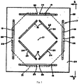
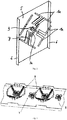
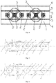
US4434425 published in 1984 with the applicant being GTE Products Corporation provides a radiation unit and proposes a solution that nests a high-frequency radiation unit within a low-frequency radiation unit, as shown inFig. 1 . Furthermore, theUS Patent No. US6333720B1 filed by the German kathrein company in 2001 provides a multiband common base station antenna for mobile communication as shown inFig. 2 in the patent publication. The Chinese Patent Publication No.CN101425626A with the applicant being Comba Telecom Systems (China) Co., Ltd. in 2007 also provides an array antenna formed by co-axially nested high and low frequencies as shown inFig. 3 . The above published patents easily realize a broadband, narrow cross-sectional multi-frequency common base station antenna with 2G/3G coaxial arrangement. The principle of implementation is based on the relationship that the center frequency of the working band of low-frequency radiation unit is close to 2 times of the center frequency of the working band of high-frequency radiation unit, the configuration that the low-frequency radiation units are nested with one high-frequency radiation unit is usually employed by simultaneously arranging a high-frequency radiation unit between two low-frequency radiation units. In the end, the distance between two neighboring low-frequency radiation units is 2 times of the distance between two neighboring high-frequency radiators. - Since what is needed by existing mobile communication systems is broadband, dual-frequency dual-polarized array antenna, the ratio of wavelengths corresponding to the center frequencies of the low-frequency band and the high-frequency band has reached a relationship greater than 2 times of frequency. For example: the working bands of 2G/3G/4G mobile communication systems are: the low-frequency band is 790 - 960 MHz and the high-frequency band is 1700 - 2700 MHz, the wavelength at the center frequency of the low-frequency band is 342 mm, while the wavelength at the center frequency of the high-frequency band is only 136.36 mm. The ratio of the two has reached 2.5 times. Along with the drastic increase of the bandwidth of high-frequency end (the bandwidth being about 45%), in particular, the highest frequency of 2700 MHz is more than 3.4 times of the low-frequency end of 790 MHz. Therefore, the relationship that the distance between low-frequency radiation units is 2 times of the distance between high-frequency units is no longer able to achieve the optimal radiation performance of the high/low frequency array antenna.
- Prior Art II: to solve the above arraying problem of dual-broad frequency antenna, please refer to
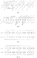
Fig. 4 . In the Patent Application with the Publication No.CN102299398A ,Claim 1 is "a dual-band and dual-polarized antenna, comprising: a reflector, and a high-frequency radiator array and a low-frequency radiator array arranged on the same side of the reflector and comprised of two or more high-frequency radiators and low-frequency radiators, respectively, the high-frequency radiators and low-frequency radiators are coaxially arranged along the axis of the reflector, characterized in that two high-frequency radiators are arranged between neighboring low-frequency radiators, and each low-frequency radiator encases a high-frequency radiator"; in addition,Claim 5 is that "every two neighboring high-frequency radiators are spaced at 106 mm, and every two neighboring low-frequency radiators are spaced at 318 mm." It can be seen fromClaim 1, together withFig. 1 andFig. 2 , that the distance between low-frequency radiators is 3 times of the distance between high-frequency radiators. According to the above analysis, the wavelength at the center frequency of the high-frequency band is 2.5 times of that of the low-frequency band in the existing mobile communication bands. Apparently, such an arraying configuration is merely an improvement, which cannot fundamentally solve the arraying problem of existing dual-broad frequency antennas. Furthermore, it can be seen with reference toClaim 5 that when the distance between high-frequency radiators is set to 106 mm, the distance between low-frequency radiators is 318 mm, the distance between low-frequency units is 1.02 times of the wavelength at the frequency of 960 MHz that is 312.5 mm. According to the array antenna theory, a distance between low-frequency radiation units that exceeds one times of the wavelength apparently has serious impact on the performance of low-frequency arrays. In particular, the gating lobe of high level will unavoidably occur in the electrical down-tilting process of the vertical face at the frequency of 960 MHz, leading to deteriorated radiation performance indices thereof. - Prior art
EP2521218A2 discloses (seefig. 4 ) alternating 1:2 and 1:3 ratios between low-frequency and high-frequency units. - The object of embodiment of the present invention is to overcome the above drawbacks by providing a multi-frequency array antenna, looking for the layout relationship between the neighboring distance of low-frequency radiation units and the neighboring distance of high-frequency radiation units so as to realize the coaxial arraying of low-frequency radiation units and high-frequency radiation units so as to be compatible with signals of current 2G, 3G and 4G mobile communication networks.
- The embodiment of the present invention is implemented with the following technical solution:
- The multi-frequency array antenna as defined in
independent claim 1 and according to the embodiment of the present invention comprises a metal reflector, a low-frequency radiation column element that is arranged on the metal reflector and operates in a first frequency band range, and a high-frequency radiation column element operating in a second frequency band range. The low-frequency radiation column element comprises several low-frequency radiation units arranged at an equal first distance in the axial direction of a first reference axis, the high-frequency radiation column element comprises several high-frequency radiation units arranged at an equal second distance in the axial direction of the first reference axis, wherein the first distance is 2.5 times of the second distance, a first one of the low-frequency radiation units is nested with one high-frequency radiation unit locationally corresponding thereto, and separately, a second one of the low-frequency radiation units is axially located between two neighboring high-frequency radiation units adjacent to the second low-frequency radiation unit and is not nested with one of the high-frequency radiation units. - Preferable embodiments are defined in the dependent claims.
- Compared with the prior art, the technical effect of the present invention is not anticipatable:
- First, in the present invention, with respect to the first distance between the low-frequency radiation units and the second distance between the high-frequency radiation units, an optimal setting is obtained by limiting the first distance to be 2.5 times of the second distance, which substantially arranges the low-frequency radiation column element and the high-frequency radiation column element on the same first reference axis, such that the electrical performance of signals in all band ranges is optimized, consequently it can be simultaneously compatible with mobile communication systems in the range of three operating bands of 2G, 3G and 4G. As a result, signal receiving and transmission can be performed for all of the current mobile communication systems, such as GSM, CDMA and LTE, with one set of multi-frequency array antenna, which solves the difficulty that has not been addressed and has obsesses those skilled in the art for many years.
- Second, by defining that the low-frequency radiation column element employs two types of low-frequency radiation units with different structures, it can effectively avoid the phenomenon that their radiation arms are overlapped when projected orthographically to the orthographical projection plane of the metal reflector, thereby minimizing the signal interference between the low-frequency radiation column element and the high-frequency radiation column element and ensuring that the multiple relationship between the above two distances is more reliable.
- Furthermore, by limiting that the first distance and the second distance are 0.6 - 1.0 times of their frequency band ranges, preferably 0.8 times, it further optimizes the entire arraying effect such that the electrical performance of the multi-frequency array antenna according to the present invention is optimized.
-
-
Fig. 1 illustrates the structure of a radiation unit according to theUS Patent Publication No. US4434425 ; -
Fig. 2 illustrates the structure of a radiation unit according to theUS Patent Publication No. US6333720B1 ; -
Fig. 3 illustrates a dual-frequency dual-polarized array antenna according to the Chinese Patent Publication No.N101425626A -
Fig. 4 illustrates a dual-frequency dual-polarized array antenna according to the Chinese Patent Publication No.CN102299398A ; -
Fig. 5 is an arraying schematic diagram of the multi-frequency array antenna according to Example 1 of the present invention with both low-frequency radiation units and high-frequency radiation units arranged on the same reference axis; -
Fig. 6 andFig. 7 are arraying schematic diagrams of the multi-frequency array antenna according to Example 2 and Example 3 of the present invention, respectively, with their low-frequency radiation units and high-frequency radiation units arranged on a plurality of reference axis, whereinFig. 7 is an alternative based onFig. 6 ; -
Fig. 8 is an arraying schematic diagram of the multi-frequency array antenna according to Example 3 of the present invention, which employs low-frequency radiation units of a unified shape; -
Fig. 9 is an arraying schematic diagram of the multi-frequency array antenna according to Example 4 of the present invention, which expands the high-frequency radiation column element based on the example disclosed inFig. 5 such that the antenna operates in three frequency band ranges; -
Fig. 10 is an arraying schematic diagram of the multi-frequency array antenna according to Example 5 of the present invention, which expands the high-frequency radiation column element and the low-frequency radiation column element based on the example disclosed inFig. 5 such that the antenna operates in four frequency band ranges; -
Fig. 11 is an arraying schematic diagram of the multi-frequency array antenna according to Example 6 of the present invention, which enables the antenna to operate in five frequency band ranges through more flexible expansion of the high-frequency radiation column element and the low-frequency radiation column element. - Examples of the present invention will be described in detail below with reference to the accompanying drawings.
- In a mobile communication antenna, radiation column elements (comprising low-frequency radiation column element and high-frequency radiation column element) are used for radiating communicating signals, which are typically formed by arranging a plurality of radiation units in a single-column matrix on a metal reflector. For high-frequency signals, the high-frequency radiation column element is formed by arranging a plurality of high-frequency radiation units at an equal distance in the axial direction of the same reference axis, and for the ease of subsequent description, the distance is defined as the second distance. Correspondingly, the low-frequency radiation column element is formed by arranging a plurality of low-frequency radiation units at an equal distance in the axial direction of the same reference axis, and similarly, the distance is defined as the second distance, wherein the part of the radiation units for performing signal transmission and receiving is the radiation arm thereof, the radiation arm is usually located at the periphery of a radiation unit and has a variety of known structures. However, they all employ the central symmetric relationship, i.e. they typically consist of two pairs of symmetric radiators in the orthogonal form, each pair of symmetric radiators comprises two of the radiation arms, and radiation arms of common radiation units mostly form a ring shape, including rectangular and circular. Of course, they may also comprise other polygonal rings; alternatively, the radiation arm may also be designed to have a shape of horizontal elongation, and the same pair of symmetric radiators is substantially elongated longitudinally, such that the radiation units after orthogonal configuration appear to be a "cross". Generally speaking, radiation arms of different symmetric radiators do not have physical contact. Radiation units may be printed in 2 dimensions, or may have a 3-D structure. These fundamental concepts will be followed in the description of all examples of the present invention. When a radiation column element is installed on a metal reflector, it is projected orthographically to the direction of the reflector to form an orthographical projection plane.
Fig. 5 to Fig. 11 of the present invention all use this orthographical projection plane for illustration so as to clearly disclose the layout relationship among different radiation column elements. - In all examples disclosed by the present invention, the low-frequency radiation column element and high-frequency radiation column element thereof all operate in different frequency band ranges, and the "low-frequency" of the low-frequency radiation column element herein indicates that it is lower than the frequency of the "high-frequency" of the high-frequency radiation column element. Preferably, the low-frequency radiation column element operates in the frequency band range of 790 - 960 MHz, which covers current 2G and 3G mobile communication frequency bands globally, while the high-frequency radiation column element operates in the frequency band range of 1700 - 2700 MHz, which covers current 4G mobile communication frequency bands globally, such as the LTE standard.
- Please refer to
Fig. 5 . The multi-frequency array antenna according to Example 1 of the present invention arranges a low-frequency radiation column element and a high-frequency radiation column element coaxially along an imaginary first reference axis a on themetal reflector 1, thereby forming a set of dual frequency common antenna. - The high-frequency radiation column element is formed by 12 high-frequency radiation units (4, 5, 6) arranged sequentially at an equal second distance in the axial direction of the first reference axis a, all of the high-frequency radiation units are arranged on the first reference axis a, and arranged in the position sequence from left to right. For the ease of description, the second distance between the locationally neighboring high-
frequency radiation units - The low-frequency radiation column element is formed by 5 low-frequency radiation units (2, 3) arranged sequentially at an equal first distance in the axial direction of the first reference axis a, all of the low-frequency radiation units are arranged on the first reference axis a, and arranged in the position sequence from left to right, wherein given the above second distance d, the first distance between two axially neighboring low-
frequency radiation units - To realize the above multiple relationship between the first distance and the second distance, according to the sequence from left to right, the low-
frequency radiation unit 2 with the position being an odd number is nested with a high-frequency radiation unit 4 that appears to be locationally corresponding due to the multiple relationship. For example, the axial 1st, 3rd and 5th low-frequency radiation units are nested with the axial 1st, 6th and 11th high-frequency radiation units, respectively. If physical error is not considered, the realization of such a nesting relationship means that, on the orthographical projection plane, the symmetry center of the radiation arm of the low-frequency radiation unit 2 is overlapped with the symmetry center of the radiation arm of the high-frequency radiation unit 4. On the other hand, the low-frequency radiation unit 3 with the position being an even number is located axially between two neighboring high-frequency radiation units 5 due to the multiple relationship, and if physical error is not considered, it is theoretically located at the exact middle between two neighboring high-frequency radiation units 5. For example, the axial 2nd and 4th low-frequency radiation units are exactly located at the exact middle between the axial 3rd and 4th, and 8th and 9th high-frequency radiation units 5, respectively. In such a way, if calculated according to the multiple relationship, the distance from the low-frequency radiation unit 3 with the position being an even number to anyradiation unit 5 that is axially neighboring to the position of the low-frequency radiation unit 3 is 0.5d. - To avoid mutual interference to signals between the low-frequency radiation units and the high-frequency radiation units, it is defined that all low-frequency radiation units with the position thereof being an odd number are the first low-
frequency radiation units 2, and that all low-frequency radiation units with the position thereof being an even number are the second low-frequency radiation units 3. In this example, the first low-frequency radiation units 2 and the second low-frequency radiation units 3 have different structural forms, which are specifically reflected by different forms of their radiation arms. With respect to a first low-frequency radiation unit 2 with the position thereof being an odd number, due to the nesting with the high-frequency radiation unit 4, the radial size of the radiation arm of the high-frequency radiation unit 4 is usually smaller than the radial size of the radiation arm of the low-frequency radiation unit 2 on the orthographical projection plane. Therefore, the radiation arm of the first low-frequency radiation unit 2 may use a ring-shaped structure. In such a way, the radiation arm of the high-frequency radiation unit 4 and the radiation arm of the first low-frequency radiation unit 2 do not have an overlapping relationship on the orthographical projection plane, which avoids or reduces mutual interference of the signals. With respect to a second low-frequency radiation unit 3 with the position thereof being an even number, on the other hand, if the same structure of radiation arm as that of the first low-frequency radiation unit 2 is still employed, then the ring-shaped radiation arm will easily cross above the two high-frequency radiation units 5 adjacent to the first low-frequency radiation unit 2, thereby leading to mutual interference of the two's signals. Thus, the radiation arm of the second low-frequency radiation unit 3 preferably has a crossing shape, i.e. the above "cross" form of radiation arm structure. With its longitudinally elongated design of symmetric radiators, therefore, the phenomenon of overlapping with the high-frequency radiation units 5 on the orthographical projection plane can be avoided. With this means, it can ensure that signals of the low-frequency radiation column element and high-frequency radiation column element do not interfere with each other, or at least the degree of interference is minimized. - In all examples of the present invention, just like this example, the low-frequency radiation column element and high-frequency radiation column element are adapted to be within the above specified ranges of operating bands, the value of the first distance between neighboring low-frequency radiation units is limited to be in the range of 262.5 - 287.5 mm, and the value of the second distance between neighboring high-frequency radiation units is limited to be in the range of 105 - 115 mm. Alternatively, the first distance and the second distance may be determined in the following manner: the first distance of the low-frequency radiation column element is 0.6 - 1.0 times of the wavelength corresponding to the center frequency of the frequency band range in which the column element operates, preferably 0.8 times; similarly, the second distance of the high-frequency radiation column element is 0.6 - 1.0 times of the wavelength corresponding to the center frequency of the frequency band range in which the column element operates, preferably 0.8 times.
- Please refer to
Fig. 6 . The multi-frequency array antenna according to Example 2 of the present invention is similarly a set of dual frequency common antenna, which, similarly to Example 1, comprises a low-frequency radiation column element and a high-frequency radiation column element, but the difference is that a part of the low-frequency radiation column element and a corresponding part of the high-frequency radiation column element are arranged to deviate from the imaginary first reference axis a. Specifically, it means that the second low-frequency radiation unit 3 and two high-frequency radiation units 5 adjacent axially thereto are no longer located on the first reference axis a, as other radiation units do, but are arranged to deviate from the first reference axis a, respectively: the adjacent two high-frequency radiation units 5 are fixedly arranged on an imaginary second reference axis (not shown) at one side of the first reference axis a, the second low-frequency radiation unit 3 is fixedly arranged on an imaginary third reference axis (not shown) at the other side of the first reference axis a, and both the second reference axis and the third reference axis are symmetric with respect to the first reference axis a and parallel to the first reference axis a. The improvement to this structure is favorable for flexible selection of the form of the radiation arm structure of the second low-frequency radiation unit, without causing concerns of signal interference with the adjacent two radiation units. In addition, this type of signal interference may theoretically be further reduced regardless of the selected form of the radiation arm structure. - It should be noted that the reason why the second reference axis and the third reference axis are imaginary but not shown is only for the purpose of description, which avoids misunderstanding by additional lines that radiation units on different reference axes are mistaken as a plurality of radiation units. The same reason applies below.
- Please refer to the multi-frequency array antenna in Example 3 disclosed by
Fig. 7 , which makes improvements to Example 2. The improvements thereof are: wherein one of the second low-frequency radiation units 3 is arranged on an imaginary third reference axis (not shown), and two high-frequency radiation units adjacent axially thereto are similarly still located on the imaginary second reference axis (not shown). However, the other second low-frequency radiation unit 3 is arranged on the imaginary second reference axis (not shown). To adapt to this change, the two high-frequency radiation units 5 adjacent axially to the second low-frequency radiation unit 3 are moved to the third reference axis. This example is substantially equivalent to Example 2, which are mutually interchangeable solutions. -
Fig. 8 further discloses the arraying solution of the multi-frequency array antenna according to Example 4 of the present invention, which performs transformation based on Example 1, and the only transformation is that all of the low-frequency radiation units employed by the low-frequency radiation column element thereof are the above second low-frequency radiation units, i.e. the form of the radiation arm structure is a "cross" shape. The unified structure form of the low-frequency radiation units is favorable for the standard execution in the production process, making the assembly more convenient and thereby improving the production efficiency. - Please refer to
Fig. 9, Fig. 10 andFig. 11 , which disclose the multi-frequency array antenna according to Example 5, Example 6 and Example 7, respectively, and disclose the implementation form to apply the multi-frequency array antenna in 3, 4 and 5 frequency bands, respectively. Among them, the 3-frequency band common antenna shown inFig. 9 is implemented based on the arraying solution in Example 1 and by providing another imaginary reference axis a2 parallel to the first reference axis a1 on the metal reflector, and arranging another high-frequency radiation column element on the reference axis a2 for processing signals in a third frequency band range; the 4-frequency band common antenna shown inFig. 10 is implemented by providing two imaginary reference axes a1 and a2 on the metal reflector, and arranging a dual-frequency common antenna structure similar to Example 1 and operating in different frequency bands on the two reference axes a1 and a2, respectively; the 5-frequency band common antenna shown inFig. 11 is implemented by providing three imaginary reference axes a1, a2 and a3 on the metal reflector, wherein the reference axis a1 is arranged with only one high-frequency radiation column element, while an arraying structure that is completely the same as Example 4 is employed on the other two reference axes a2 and a3 that are arranged symmetrically with respect to a1. It can be seen from the examples inFig. 9 through Fig. 11 that the multi-frequency array antenna according to the present invention may achieve an antenna with two or more common frequency bands by flexibly adding a plurality of low-frequency radiation column elements and/or high-frequency radiation column elements and assigning identical or different ranges of operating frequency bands thereto. - The second distance arranged in the axial direction of the first reference axis a for the distance between high-frequency radiation units in the above examples may also be fine-tuned according to specific implementation situations and arranged to be close to an equal distance. Similarly, the first distance 2.5d arranged in the axial direction of the first reference axis a for the distance between low-frequency radiation units may also be fine-tuned according to specific implementation situations and arranged to be close to an equal distance. All of those skilled in the art are aware of such variations.
- It should be noted that when the distance between high-frequency radiation units is not an equal distance, the axial distance between low-frequency radiation units is not strictly 2.5 times, but changes to an equivalent relative position close to 2.5 times. Namely, the physical center of the low-frequency radiation unit that is not nested with high-frequency is located between two high-frequency radiation units locationally corresponding thereto.
- All examples of the present invention achieve unanticipated effect and can realize compatibility with 2G, 3G and 4G signals. According to the current mobile communication systems 2G/3G/LTE, the frequency band range in which the low-frequency radiation column element operates may be 790 - 960 MHz and the frequency band range in which the high-frequency radiation column element operates may be 1700 - 2700 MHz, based on which the center frequencies of the high-frequency radiation column element and the low-frequency radiation column element are calculated to be f1 = 2200 MHz and f2 = 875 MHz, respectively. It can be seen that it exactly satisfies the relationship of f1/f2 ≈ 2.5 times.
- In summary, the present invention optimally meets the current arraying need by super wide frequency common antennas, greatly improves the electrical performance of the antennas, and at the same time, realizes overall miniaturization of the antennas.
- It should be noted that the above examples are only used to describe the present invention, rather than limit the technical solution described by the present invention; although the Specification has provided a detailed description of the present invention with reference to the above examples, therefore, those skilled in the art should understand that modifications may still be made to the present invention. The invention is defined by the scope of the claims.
Claims (15)
- A multi-frequency array antenna, comprising: a metal reflector (1), a low-frequency radiation column element that is arranged on the metal reflector (1) and operates in a first frequency band range, and a high-frequency radiation column element operating in a second frequency band range, wherein:the low-frequency radiation column element comprising several low-frequency radiation units (2,3) arranged at an equal first distance in the axial direction of a first reference axis (α),the high-frequency radiation column element comprising several high-frequency radiation units (4,5,6) arranged at an equal second distance in the axial direction of the first reference axis (α), characterized in that the first distance is 2.5 times of the second distance, a first one of the low-frequency radiation units (2) is nested with one high-frequency radiation unit (4) locationally corresponding thereto, and separately, a second one of the low-frequency radiation units (3) is axially located between two neighboring high-frequency radiation units (5) adjacent to the second low-frequency radiation unit (3) and is not nested with one of the high-frequency radiation units (4,5,6).
- The multi-frequency array antenna according to Claim 1, characterized in that the first low-frequency radiation unit (2) and each of the other low-frequency radiation units (2) with the axial positions on the first reference axis (α) being an odd or even number is nested with one high-frequency radiation unit (4) locationally corresponding thereto, and the second low-frequency radiation unit (3) and each of the other low-frequency units (3) which are oppositely an even or odd number are scattered between two neighboring high-frequency radiation units (5) axially adjacent to said low-frequency radiation units (3) and are not nested with one of the high-frequency radiation units (4,5,6).
- The multi-frequency array antenna according to Claim 1, characterized in that both the low-frequency radiation units (2,3) and the high-frequency radiation units (4,5,6) comprise a radiation arm for radiating signals in their band ranges, and when projected orthographically to the orthographical projection plane of the metal reflector (1), there is no overlapping between all radiation arms of the low-frequency radiation units (2,3) and radiation arms of the high-frequency radiation units (4,5,6).
- The multi-frequency array antenna according to Claim 3, characterized in that for the mutually nested low-frequency radiation units (3) and high-frequency radiation units (4), their own radiation arms are in a relationship of central symmetry, and when projected orthographically to the orthographical projection plane of the metal reflector (1), the two's symmetry centers are overlapped.
- The multi-frequency array antenna according to Claim 1, characterized in that the low frequency radiation column element comprises two types of low frequency radiation units having different radiation arm structures, wherein the low-frequency radiation units of the first type (2) and the low-frequency radiation units of the second type (3) are located at the odd numbered and even numbered positions in said axial direction, respectively.
- The multi-frequency array antenna according to Claim 5, characterized in that when projected orthographically to the orthographical projection plane of the metal reflector (1), the radiation arm of the low-frequency radiation units of the first type (2) are of any ring shape, including rectangular and circular.
- The multi-frequency array antenna according to Claim 6, characterized in that when projected orthographically to the orthographical projection plane of the metal reflector (1), the radiation arm of the low-frequency radiation units of the second type (3) are of a crossing shape with an orthogonal relationship.
- The multi-frequency array antenna according to Claim 5, characterized in that the low-frequency radiation units (2, 3) are arranged at positions on the reference axis (α).
- The multi-frequency array antenna according to Claim 8, characterized in that the high-frequency radiation units (3) are arranged at positions on the reference axis (α).
- The multi-frequency array antenna according to Claim 1, characterized in that the first distance of the low-frequency radiation column element is 0.6 - 1.0 times of the wavelength corresponding to the center frequency of the first frequency band range.
- The multi-frequency array antenna according to Claim 10, characterized in that the first distance of the low-frequency radiation column element is 0.8 times of the wavelength corresponding to the center frequency of the first frequency band range.
- The multi-frequency array antenna according to Claim 1, characterized in that the second distance of the high-frequency radiation column element is 0.6 - 1.0 times of the wavelength corresponding to the center frequency of the second frequency band range.
- The multi-frequency array antenna according to Claim 12, characterized in that the second distance of the high-frequency radiation column element is 0.8 times of the wavelength corresponding to the center frequency of the second frequency band range.
- The multi-frequency array antenna according to any one of Claims 1-7 and 10-13 characterized in that at least one of the low-frequency radiation units (3) axially arranged between two neighboring high-frequency radiation units (5) is fixed on a second reference axis (α2), while the two high-frequency radiation units (5) adjacent thereto are fixed on a third reference axis (α3), and the second reference axis (α2) and the third reference axis (α3) are symmetric with respect to and parallel to the first reference axis (α).
- The multi-frequency array antenna according to Claim 1, characterized in that:the first low-frequency radiation unit (2) and the high-frequency radiation unit (4) nested therein are axially disposed a distance "d" from an adjacent high-frequency radiation unit (6),the axial distance between the first and second low-frequency radiation units (2,3) is 2.5d, andthe axial distance between the second low-frequency radiation unit (3) and one of the neighboring high-frequency radiation units (5) is 0.5d.
Applications Claiming Priority (2)
| Application Number | Priority Date | Filing Date | Title |
|---|---|---|---|
| CN2012105050811A CN102969575A (en) | 2012-11-30 | 2012-11-30 | Multi-frequency array antenna |
| PCT/CN2013/085858 WO2014082510A1 (en) | 2012-11-30 | 2013-10-24 | Multi-frequency array antenna |
Publications (3)
| Publication Number | Publication Date |
|---|---|
| EP2928019A1 EP2928019A1 (en) | 2015-10-07 |
| EP2928019A4 EP2928019A4 (en) | 2015-11-18 |
| EP2928019B1 true EP2928019B1 (en) | 2019-07-24 |
Family
ID=47799550
Family Applications (1)
| Application Number | Title | Priority Date | Filing Date |
|---|---|---|---|
| EP13858188.9A Active EP2928019B1 (en) | 2012-11-30 | 2013-10-24 | Multi-frequency array antenna |
Country Status (6)
| Country | Link |
|---|---|
| US (1) | US9831553B2 (en) |
| EP (1) | EP2928019B1 (en) |
| CN (1) | CN102969575A (en) |
| BR (1) | BR112015012356A2 (en) |
| ES (1) | ES2750398T3 (en) |
| WO (1) | WO2014082510A1 (en) |
Families Citing this family (37)
| Publication number | Priority date | Publication date | Assignee | Title |
|---|---|---|---|---|
| CN102969575A (en) | 2012-11-30 | 2013-03-13 | 京信通信系统(中国)有限公司 | Multi-frequency array antenna |
| CN103560337B (en) * | 2013-10-25 | 2016-03-09 | 广东博纬通信科技有限公司 | A kind of multi-band array antenna |
| CN203813033U (en) * | 2013-12-23 | 2014-09-03 | 华为技术有限公司 | Multi-frequency array antenna |
| CN103715522B (en) * | 2014-01-20 | 2016-09-14 | 武汉虹信通信技术有限责任公司 | A kind of multi-antenna array supporting multi-standard |
| CN106207398B (en) * | 2015-04-30 | 2023-08-25 | 上海诺基亚贝尔股份有限公司 | An Antenna Platform with Dual Broadband Cross-polarization |
| WO2017091307A1 (en) * | 2015-11-25 | 2017-06-01 | Commscope Technologies Llc | Phased array antennas having decoupling units |
| CN106207490B (en) * | 2016-08-18 | 2021-06-25 | 京信通信技术(广州)有限公司 | Multisystem common antenna |
| CN109661751B (en) * | 2016-09-08 | 2021-06-11 | 瑞典爱立信有限公司 | Antenna array and device comprising an antenna array and a network node |
| HRP20221148T1 (en) * | 2016-11-09 | 2022-11-25 | Tongyu Communication Inc. | Dual-band radiation system and antenna array thereof |
| CN106654603B (en) * | 2016-12-28 | 2023-12-29 | 深圳国人无线通信有限公司 | Three-frequency ultra-wide band antenna with base station |
| CN106848603A (en) * | 2017-01-23 | 2017-06-13 | 武汉虹信通信技术有限责任公司 | A kind of multifrequency antenna array of low-and high-frequency combination |
| CN109219905B (en) * | 2017-01-24 | 2021-12-07 | 康普技术有限责任公司 | Base station antenna unit and method for installing base station antenna unit |
| CN107808045A (en) * | 2017-10-25 | 2018-03-16 | 四川莱源科技有限公司 | A kind of dual-band antenna array emulation design method |
| CN107768808B (en) * | 2017-11-13 | 2024-06-04 | 广东通宇通讯股份有限公司 | Multi-frequency base station antenna and reflecting piece applied to base station antenna |
| CN107681270B (en) * | 2017-11-23 | 2020-11-17 | 广东通宇通讯股份有限公司 | Base station antenna and beam shaping method thereof |
| CN107959126B (en) * | 2017-12-13 | 2024-02-27 | 华诺星空技术股份有限公司 | Antenna device for passive detection and positioning of anti-unmanned aerial vehicle |
| WO2019147769A2 (en) * | 2018-01-24 | 2019-08-01 | John Mezzalingua Associates, LLC | Fast rolloff antenna array face with heterogeneous antenna arrangement |
| EP3751665A4 (en) * | 2018-02-06 | 2021-04-07 | Comba Telecom Technology (Guangzhou) Limited | MULTI-STANDARD INTEGRATED ANTENNA |
| US11101562B2 (en) * | 2018-06-13 | 2021-08-24 | Mediatek Inc. | Multi-band dual-polarized antenna structure and wireless communication device using the same |
| CN110429392B (en) * | 2019-07-23 | 2024-06-14 | 广东博纬通信科技有限公司 | Hybrid array antenna |
| US11336006B2 (en) | 2019-10-21 | 2022-05-17 | Microsoft Technology Licensing, Llc | Isolating antenna array component |
| CN111029741B (en) * | 2019-12-06 | 2022-03-25 | 京信通信技术(广州)有限公司 | Antenna array structure and communication equipment |
| KR102764145B1 (en) * | 2020-09-15 | 2025-02-07 | 타이코에이엠피 주식회사 | Antenna device |
| CN112310661B (en) * | 2020-09-30 | 2023-07-28 | 中信科移动通信技术股份有限公司 | Multi-frequency antenna array and base station system |
| CN112736470B (en) * | 2020-12-01 | 2023-08-25 | 中信科移动通信技术股份有限公司 | Multi-frequency array antenna and base station |
| CN113036452B (en) * | 2021-03-04 | 2022-11-01 | 武汉虹信科技发展有限责任公司 | Multi-standard fusion antenna array |
| CN113097748B (en) * | 2021-04-02 | 2022-09-27 | 重庆邮电大学 | Multi-frequency antenna array suitable for multi-standard base station |
| CN113067143B (en) * | 2021-04-29 | 2026-01-27 | 深圳市道通智能航空技术股份有限公司 | An antenna and a remote control |
| CN115275642B (en) * | 2021-04-30 | 2026-04-14 | 华为技术有限公司 | Antenna array, antenna module and electronic equipment |
| CN113471666B (en) * | 2021-05-14 | 2022-12-06 | 上海交通大学 | Multi-frequency transmission base station antenna and communication system |
| CN114221140B (en) * | 2021-12-30 | 2024-08-27 | 京信通信技术(广州)有限公司 | Multi-frequency omnidirectional antenna |
| CN115275565B (en) * | 2022-07-26 | 2025-01-17 | 南通大学 | Structural multiplexing low-frequency oscillator and coaxial nested base station antenna |
| CN117996421B (en) * | 2022-10-31 | 2025-11-04 | 华为技术有限公司 | An antenna system and base station |
| CN116093635B (en) * | 2023-01-05 | 2026-07-03 | 中信科移动通信技术股份有限公司 | Array antenna |
| CN116073102B (en) * | 2023-03-31 | 2023-06-30 | 深圳市鑫龙通信技术有限公司 | Low frequency radiating element and antenna |
| CN121367046A (en) * | 2024-07-17 | 2026-01-20 | 户外无线网络有限公司 | Base station antenna |
| CN121261098A (en) * | 2025-09-28 | 2026-01-02 | 摩比天线技术(深圳)有限公司 | Antenna structure |
Citations (1)
| Publication number | Priority date | Publication date | Assignee | Title |
|---|---|---|---|---|
| US20040252071A1 (en) * | 2002-03-26 | 2004-12-16 | Bisiules Peter John | Multiband dual polarized adjustable beamtilt base station antenna |
Family Cites Families (13)
| Publication number | Priority date | Publication date | Assignee | Title |
|---|---|---|---|---|
| US4434425A (en) | 1982-02-02 | 1984-02-28 | Gte Products Corporation | Multiple ring dipole array |
| DE19823749C2 (en) | 1998-05-27 | 2002-07-11 | Kathrein Werke Kg | Dual polarized multi-range antenna |
| FR2863111B1 (en) * | 2003-12-01 | 2006-04-14 | Jacquelot | ANTENNA IN MULTI-BAND NETWORK WITH DOUBLE POLARIZATION |
| CN101425626B (en) | 2007-10-30 | 2013-10-16 | 京信通信系统(中国)有限公司 | Wide-band annular dual polarized radiating element and linear array antenna |
| CN201910482U (en) * | 2010-11-22 | 2011-07-27 | 西安俊智电子科技有限公司 | Radiating unit of 2G/3G detachable integrated antenna for mobile communication |
| CN102157780B (en) * | 2011-01-30 | 2015-03-11 | 广东通宇通讯股份有限公司 | Multi-standard antenna |
| US8674895B2 (en) * | 2011-05-03 | 2014-03-18 | Andrew Llc | Multiband antenna |
| SE535830C2 (en) * | 2011-05-05 | 2013-01-08 | Powerwave Technologies Sweden | Antenna array and a multi-band antenna |
| CN102299398B (en) * | 2011-05-20 | 2013-12-25 | 广东通宇通讯股份有限公司 | Dual-frequency dual-polarized antenna |
| CN102509897A (en) * | 2011-11-24 | 2012-06-20 | 武汉虹信通信技术有限责任公司 | Planar double-helix array of double-frequency dual-polarization base-station antenna |
| CN202474220U (en) * | 2012-02-09 | 2012-10-03 | 武汉虹信通信技术有限责任公司 | Interlaced multifrequency shared multi-antenna array structure |
| CN203134986U (en) * | 2012-11-30 | 2013-08-14 | 京信通信系统(中国)有限公司 | Multi-frequency array antenna |
| CN102969575A (en) * | 2012-11-30 | 2013-03-13 | 京信通信系统(中国)有限公司 | Multi-frequency array antenna |
-
2012
- 2012-11-30 CN CN2012105050811A patent/CN102969575A/en active Pending
-
2013
- 2013-10-24 EP EP13858188.9A patent/EP2928019B1/en active Active
- 2013-10-24 US US14/442,975 patent/US9831553B2/en active Active
- 2013-10-24 WO PCT/CN2013/085858 patent/WO2014082510A1/en not_active Ceased
- 2013-10-24 BR BR112015012356A patent/BR112015012356A2/en not_active Application Discontinuation
- 2013-10-24 ES ES13858188T patent/ES2750398T3/en active Active
Patent Citations (1)
| Publication number | Priority date | Publication date | Assignee | Title |
|---|---|---|---|---|
| US20040252071A1 (en) * | 2002-03-26 | 2004-12-16 | Bisiules Peter John | Multiband dual polarized adjustable beamtilt base station antenna |
Also Published As
| Publication number | Publication date |
|---|---|
| US20150288065A1 (en) | 2015-10-08 |
| BR112015012356A2 (en) | 2017-07-11 |
| EP2928019A4 (en) | 2015-11-18 |
| EP2928019A1 (en) | 2015-10-07 |
| US9831553B2 (en) | 2017-11-28 |
| ES2750398T3 (en) | 2020-03-25 |
| CN102969575A (en) | 2013-03-13 |
| WO2014082510A1 (en) | 2014-06-05 |
Similar Documents
| Publication | Publication Date | Title |
|---|---|---|
| US9831553B2 (en) | Multi-frequency array antenna | |
| CN205303691U (en) | Dual -frenquency double polarization base station antenna | |
| EP3739687B1 (en) | Antenna radiation element and antenna | |
| CN203134986U (en) | Multi-frequency array antenna | |
| JP5658359B2 (en) | Double polarized radiating element of multi-band antenna | |
| US10957991B2 (en) | Planar array antenna and communications device | |
| CN206225553U (en) | Bipolar radiator, antenna assembly and base station system | |
| US10374671B2 (en) | Complex antenna | |
| CN107611611B (en) | Miniaturized ultra-wideband multisystem array antenna | |
| CN103560335B (en) | Multi-band array antenna | |
| CN105379006B (en) | Dual-polarization omnidirectional antenna | |
| US20150364832A1 (en) | An antenna arrangement and a base station | |
| CN111066203B (en) | Multi-band antenna array | |
| CN106129596A (en) | Antenna radiation unit and multiple frequency broad band antenna for base station | |
| CN106252903B (en) | Dual-frequency two-beam antenna array and dual-frequency two-beam antenna | |
| CN113097748A (en) | Multi-frequency antenna array suitable for multi-standard base station | |
| CN106602223B (en) | Low-frequency radiation unit | |
| CN106169644A (en) | A split ultra-broadband dual-polarized radiation unit and base station antenna | |
| CN110265795A (en) | Multi-frequency narrow beam antenna | |
| CN112467403B (en) | Dual-frenquency common bore phased array antenna device suitable for Sub 6G | |
| CN114335996B (en) | Multi-sector antenna | |
| CN205846249U (en) | Antenna assembly | |
| CN107768808B (en) | Multi-frequency base station antenna and reflecting piece applied to base station antenna | |
| CN205752558U (en) | Dual frequency array antenna | |
| CN206116609U (en) | A split ultra-broadband dual-polarized radiation unit and base station antenna |
Legal Events
| Date | Code | Title | Description |
|---|---|---|---|
| PUAI | Public reference made under article 153(3) epc to a published international application that has entered the european phase |
Free format text: ORIGINAL CODE: 0009012 |
|
| 17P | Request for examination filed |
Effective date: 20150619 |
|
| AK | Designated contracting states |
Kind code of ref document: A1 Designated state(s): AL AT BE BG CH CY CZ DE DK EE ES FI FR GB GR HR HU IE IS IT LI LT LU LV MC MK MT NL NO PL PT RO RS SE SI SK SM TR |
|
| AX | Request for extension of the european patent |
Extension state: BA ME |
|
| RA4 | Supplementary search report drawn up and despatched (corrected) |
Effective date: 20151019 |
|
| RIC1 | Information provided on ipc code assigned before grant |
Ipc: H01Q 19/10 20060101ALI20151013BHEP Ipc: H01Q 9/26 20060101ALI20151013BHEP Ipc: H01Q 5/42 20150101ALI20151013BHEP Ipc: H01Q 21/26 20060101ALI20151013BHEP Ipc: H01Q 1/24 20060101AFI20151013BHEP |
|
| DAX | Request for extension of the european patent (deleted) | ||
| GRAP | Despatch of communication of intention to grant a patent |
Free format text: ORIGINAL CODE: EPIDOSNIGR1 |
|
| STAA | Information on the status of an ep patent application or granted ep patent |
Free format text: STATUS: GRANT OF PATENT IS INTENDED |
|
| INTG | Intention to grant announced |
Effective date: 20190214 |
|
| GRAS | Grant fee paid |
Free format text: ORIGINAL CODE: EPIDOSNIGR3 |
|
| GRAA | (expected) grant |
Free format text: ORIGINAL CODE: 0009210 |
|
| STAA | Information on the status of an ep patent application or granted ep patent |
Free format text: STATUS: THE PATENT HAS BEEN GRANTED |
|
| AK | Designated contracting states |
Kind code of ref document: B1 Designated state(s): AL AT BE BG CH CY CZ DE DK EE ES FI FR GB GR HR HU IE IS IT LI LT LU LV MC MK MT NL NO PL PT RO RS SE SI SK SM TR |
|
| REG | Reference to a national code |
Ref country code: GB Ref legal event code: FG4D |
|
| REG | Reference to a national code |
Ref country code: CH Ref legal event code: EP |
|
| REG | Reference to a national code |
Ref country code: DE Ref legal event code: R096 Ref document number: 602013058312 Country of ref document: DE |
|
| REG | Reference to a national code |
Ref country code: AT Ref legal event code: REF Ref document number: 1159308 Country of ref document: AT Kind code of ref document: T Effective date: 20190815 |
|
| REG | Reference to a national code |
Ref country code: IE Ref legal event code: FG4D |
|
| REG | Reference to a national code |
Ref country code: NL Ref legal event code: MP Effective date: 20190724 |
|
| REG | Reference to a national code |
Ref country code: LT Ref legal event code: MG4D |
|
| REG | Reference to a national code |
Ref country code: AT Ref legal event code: MK05 Ref document number: 1159308 Country of ref document: AT Kind code of ref document: T Effective date: 20190724 |
|
| PG25 | Lapsed in a contracting state [announced via postgrant information from national office to epo] |
Ref country code: BG Free format text: LAPSE BECAUSE OF FAILURE TO SUBMIT A TRANSLATION OF THE DESCRIPTION OR TO PAY THE FEE WITHIN THE PRESCRIBED TIME-LIMIT Effective date: 20191024 Ref country code: NL Free format text: LAPSE BECAUSE OF FAILURE TO SUBMIT A TRANSLATION OF THE DESCRIPTION OR TO PAY THE FEE WITHIN THE PRESCRIBED TIME-LIMIT Effective date: 20190724 Ref country code: PT Free format text: LAPSE BECAUSE OF FAILURE TO SUBMIT A TRANSLATION OF THE DESCRIPTION OR TO PAY THE FEE WITHIN THE PRESCRIBED TIME-LIMIT Effective date: 20191125 Ref country code: HR Free format text: LAPSE BECAUSE OF FAILURE TO SUBMIT A TRANSLATION OF THE DESCRIPTION OR TO PAY THE FEE WITHIN THE PRESCRIBED TIME-LIMIT Effective date: 20190724 Ref country code: LT Free format text: LAPSE BECAUSE OF FAILURE TO SUBMIT A TRANSLATION OF THE DESCRIPTION OR TO PAY THE FEE WITHIN THE PRESCRIBED TIME-LIMIT Effective date: 20190724 Ref country code: NO Free format text: LAPSE BECAUSE OF FAILURE TO SUBMIT A TRANSLATION OF THE DESCRIPTION OR TO PAY THE FEE WITHIN THE PRESCRIBED TIME-LIMIT Effective date: 20191024 Ref country code: AT Free format text: LAPSE BECAUSE OF FAILURE TO SUBMIT A TRANSLATION OF THE DESCRIPTION OR TO PAY THE FEE WITHIN THE PRESCRIBED TIME-LIMIT Effective date: 20190724 Ref country code: FI Free format text: LAPSE BECAUSE OF FAILURE TO SUBMIT A TRANSLATION OF THE DESCRIPTION OR TO PAY THE FEE WITHIN THE PRESCRIBED TIME-LIMIT Effective date: 20190724 Ref country code: SE Free format text: LAPSE BECAUSE OF FAILURE TO SUBMIT A TRANSLATION OF THE DESCRIPTION OR TO PAY THE FEE WITHIN THE PRESCRIBED TIME-LIMIT Effective date: 20190724 |
|
| PG25 | Lapsed in a contracting state [announced via postgrant information from national office to epo] |
Ref country code: IS Free format text: LAPSE BECAUSE OF FAILURE TO SUBMIT A TRANSLATION OF THE DESCRIPTION OR TO PAY THE FEE WITHIN THE PRESCRIBED TIME-LIMIT Effective date: 20191124 Ref country code: RS Free format text: LAPSE BECAUSE OF FAILURE TO SUBMIT A TRANSLATION OF THE DESCRIPTION OR TO PAY THE FEE WITHIN THE PRESCRIBED TIME-LIMIT Effective date: 20190724 Ref country code: LV Free format text: LAPSE BECAUSE OF FAILURE TO SUBMIT A TRANSLATION OF THE DESCRIPTION OR TO PAY THE FEE WITHIN THE PRESCRIBED TIME-LIMIT Effective date: 20190724 Ref country code: GR Free format text: LAPSE BECAUSE OF FAILURE TO SUBMIT A TRANSLATION OF THE DESCRIPTION OR TO PAY THE FEE WITHIN THE PRESCRIBED TIME-LIMIT Effective date: 20191025 Ref country code: AL Free format text: LAPSE BECAUSE OF FAILURE TO SUBMIT A TRANSLATION OF THE DESCRIPTION OR TO PAY THE FEE WITHIN THE PRESCRIBED TIME-LIMIT Effective date: 20190724 |
|
| REG | Reference to a national code |
Ref country code: ES Ref legal event code: FG2A Ref document number: 2750398 Country of ref document: ES Kind code of ref document: T3 Effective date: 20200325 |
|
| PG25 | Lapsed in a contracting state [announced via postgrant information from national office to epo] |
Ref country code: TR Free format text: LAPSE BECAUSE OF FAILURE TO SUBMIT A TRANSLATION OF THE DESCRIPTION OR TO PAY THE FEE WITHIN THE PRESCRIBED TIME-LIMIT Effective date: 20190724 |
|
| PG25 | Lapsed in a contracting state [announced via postgrant information from national office to epo] |
Ref country code: RO Free format text: LAPSE BECAUSE OF FAILURE TO SUBMIT A TRANSLATION OF THE DESCRIPTION OR TO PAY THE FEE WITHIN THE PRESCRIBED TIME-LIMIT Effective date: 20190724 Ref country code: IT Free format text: LAPSE BECAUSE OF FAILURE TO SUBMIT A TRANSLATION OF THE DESCRIPTION OR TO PAY THE FEE WITHIN THE PRESCRIBED TIME-LIMIT Effective date: 20190724 Ref country code: EE Free format text: LAPSE BECAUSE OF FAILURE TO SUBMIT A TRANSLATION OF THE DESCRIPTION OR TO PAY THE FEE WITHIN THE PRESCRIBED TIME-LIMIT Effective date: 20190724 Ref country code: DK Free format text: LAPSE BECAUSE OF FAILURE TO SUBMIT A TRANSLATION OF THE DESCRIPTION OR TO PAY THE FEE WITHIN THE PRESCRIBED TIME-LIMIT Effective date: 20190724 Ref country code: PL Free format text: LAPSE BECAUSE OF FAILURE TO SUBMIT A TRANSLATION OF THE DESCRIPTION OR TO PAY THE FEE WITHIN THE PRESCRIBED TIME-LIMIT Effective date: 20190724 |
|
| REG | Reference to a national code |
Ref country code: DE Ref legal event code: R119 Ref document number: 602013058312 Country of ref document: DE |
|
| PG25 | Lapsed in a contracting state [announced via postgrant information from national office to epo] |
Ref country code: CZ Free format text: LAPSE BECAUSE OF FAILURE TO SUBMIT A TRANSLATION OF THE DESCRIPTION OR TO PAY THE FEE WITHIN THE PRESCRIBED TIME-LIMIT Effective date: 20190724 Ref country code: MC Free format text: LAPSE BECAUSE OF FAILURE TO SUBMIT A TRANSLATION OF THE DESCRIPTION OR TO PAY THE FEE WITHIN THE PRESCRIBED TIME-LIMIT Effective date: 20190724 Ref country code: SK Free format text: LAPSE BECAUSE OF FAILURE TO SUBMIT A TRANSLATION OF THE DESCRIPTION OR TO PAY THE FEE WITHIN THE PRESCRIBED TIME-LIMIT Effective date: 20190724 Ref country code: IS Free format text: LAPSE BECAUSE OF FAILURE TO SUBMIT A TRANSLATION OF THE DESCRIPTION OR TO PAY THE FEE WITHIN THE PRESCRIBED TIME-LIMIT Effective date: 20200224 Ref country code: SM Free format text: LAPSE BECAUSE OF FAILURE TO SUBMIT A TRANSLATION OF THE DESCRIPTION OR TO PAY THE FEE WITHIN THE PRESCRIBED TIME-LIMIT Effective date: 20190724 |
|
| REG | Reference to a national code |
Ref country code: CH Ref legal event code: PL |
|
| PLBE | No opposition filed within time limit |
Free format text: ORIGINAL CODE: 0009261 |
|
| STAA | Information on the status of an ep patent application or granted ep patent |
Free format text: STATUS: NO OPPOSITION FILED WITHIN TIME LIMIT |
|
| PG2D | Information on lapse in contracting state deleted |
Ref country code: IS |
|
| PG25 | Lapsed in a contracting state [announced via postgrant information from national office to epo] |
Ref country code: CH Free format text: LAPSE BECAUSE OF NON-PAYMENT OF DUE FEES Effective date: 20191031 Ref country code: LI Free format text: LAPSE BECAUSE OF NON-PAYMENT OF DUE FEES Effective date: 20191031 Ref country code: DE Free format text: LAPSE BECAUSE OF NON-PAYMENT OF DUE FEES Effective date: 20200501 Ref country code: LU Free format text: LAPSE BECAUSE OF NON-PAYMENT OF DUE FEES Effective date: 20191024 |
|
| 26N | No opposition filed |
Effective date: 20200603 |
|
| REG | Reference to a national code |
Ref country code: BE Ref legal event code: MM Effective date: 20191031 |
|
| PG25 | Lapsed in a contracting state [announced via postgrant information from national office to epo] |
Ref country code: SI Free format text: LAPSE BECAUSE OF FAILURE TO SUBMIT A TRANSLATION OF THE DESCRIPTION OR TO PAY THE FEE WITHIN THE PRESCRIBED TIME-LIMIT Effective date: 20190724 Ref country code: BE Free format text: LAPSE BECAUSE OF NON-PAYMENT OF DUE FEES Effective date: 20191031 |
|
| PG25 | Lapsed in a contracting state [announced via postgrant information from national office to epo] |
Ref country code: FR Free format text: LAPSE BECAUSE OF NON-PAYMENT OF DUE FEES Effective date: 20191031 Ref country code: IE Free format text: LAPSE BECAUSE OF NON-PAYMENT OF DUE FEES Effective date: 20191024 |
|
| REG | Reference to a national code |
Ref country code: GB Ref legal event code: 732E Free format text: REGISTERED BETWEEN 20210128 AND 20210203 |
|
| REG | Reference to a national code |
Ref country code: ES Ref legal event code: PC2A Owner name: COMBA TELECOM TECHNOLOGY (GUANGZHOU) LIMITED Effective date: 20210303 |
|
| PG25 | Lapsed in a contracting state [announced via postgrant information from national office to epo] |
Ref country code: CY Free format text: LAPSE BECAUSE OF FAILURE TO SUBMIT A TRANSLATION OF THE DESCRIPTION OR TO PAY THE FEE WITHIN THE PRESCRIBED TIME-LIMIT Effective date: 20190724 |
|
| PG25 | Lapsed in a contracting state [announced via postgrant information from national office to epo] |
Ref country code: HU Free format text: LAPSE BECAUSE OF FAILURE TO SUBMIT A TRANSLATION OF THE DESCRIPTION OR TO PAY THE FEE WITHIN THE PRESCRIBED TIME-LIMIT; INVALID AB INITIO Effective date: 20131024 Ref country code: MT Free format text: LAPSE BECAUSE OF FAILURE TO SUBMIT A TRANSLATION OF THE DESCRIPTION OR TO PAY THE FEE WITHIN THE PRESCRIBED TIME-LIMIT Effective date: 20190724 |
|
| PG25 | Lapsed in a contracting state [announced via postgrant information from national office to epo] |
Ref country code: MK Free format text: LAPSE BECAUSE OF FAILURE TO SUBMIT A TRANSLATION OF THE DESCRIPTION OR TO PAY THE FEE WITHIN THE PRESCRIBED TIME-LIMIT Effective date: 20190724 |
|
| P01 | Opt-out of the competence of the unified patent court (upc) registered |
Effective date: 20230517 |
|
| PGFP | Annual fee paid to national office [announced via postgrant information from national office to epo] |
Ref country code: GB Payment date: 20241025 Year of fee payment: 12 |
|
| PGFP | Annual fee paid to national office [announced via postgrant information from national office to epo] |
Ref country code: ES Payment date: 20241127 Year of fee payment: 12 |
|
| GBPC | Gb: european patent ceased through non-payment of renewal fee |
Effective date: 20251024 |
|
| PG25 | Lapsed in a contracting state [announced via postgrant information from national office to epo] |
Ref country code: GB Free format text: LAPSE BECAUSE OF NON-PAYMENT OF DUE FEES Effective date: 20251024 |