EP2927791A1 - Procédé et dispositif de préparation d'une interface utilisateur graphique dans un véhicule - Google Patents
Procédé et dispositif de préparation d'une interface utilisateur graphique dans un véhicule Download PDFInfo
- Publication number
- EP2927791A1 EP2927791A1 EP15158648.4A EP15158648A EP2927791A1 EP 2927791 A1 EP2927791 A1 EP 2927791A1 EP 15158648 A EP15158648 A EP 15158648A EP 2927791 A1 EP2927791 A1 EP 2927791A1
- Authority
- EP
- European Patent Office
- Prior art keywords
- display
- area
- display area
- displayed
- user device
- Prior art date
- Legal status (The legal status is an assumption and is not a legal conclusion. Google has not performed a legal analysis and makes no representation as to the accuracy of the status listed.)
- Granted
Links
Images


Classifications
-
- G—PHYSICS
- G06—COMPUTING; CALCULATING OR COUNTING
- G06F—ELECTRIC DIGITAL DATA PROCESSING
- G06F3/00—Input arrangements for transferring data to be processed into a form capable of being handled by the computer; Output arrangements for transferring data from processing unit to output unit, e.g. interface arrangements
- G06F3/01—Input arrangements or combined input and output arrangements for interaction between user and computer
- G06F3/048—Interaction techniques based on graphical user interfaces [GUI]
- G06F3/0484—Interaction techniques based on graphical user interfaces [GUI] for the control of specific functions or operations, e.g. selecting or manipulating an object, an image or a displayed text element, setting a parameter value or selecting a range
- G06F3/0486—Drag-and-drop
-
- G—PHYSICS
- G06—COMPUTING; CALCULATING OR COUNTING
- G06F—ELECTRIC DIGITAL DATA PROCESSING
- G06F3/00—Input arrangements for transferring data to be processed into a form capable of being handled by the computer; Output arrangements for transferring data from processing unit to output unit, e.g. interface arrangements
- G06F3/01—Input arrangements or combined input and output arrangements for interaction between user and computer
- G06F3/048—Interaction techniques based on graphical user interfaces [GUI]
- G06F3/0487—Interaction techniques based on graphical user interfaces [GUI] using specific features provided by the input device, e.g. functions controlled by the rotation of a mouse with dual sensing arrangements, or of the nature of the input device, e.g. tap gestures based on pressure sensed by a digitiser
- G06F3/0488—Interaction techniques based on graphical user interfaces [GUI] using specific features provided by the input device, e.g. functions controlled by the rotation of a mouse with dual sensing arrangements, or of the nature of the input device, e.g. tap gestures based on pressure sensed by a digitiser using a touch-screen or digitiser, e.g. input of commands through traced gestures
Definitions
- the present invention relates to a method and apparatus for providing a graphical user interface in a vehicle.
- Modern vehicles include, for example, a variety of driver assistance systems whose information must be displayed in the vehicle.
- vehicles often include a navigation system. By means of such a navigation system digital geographic road maps can be displayed with a route and, where appropriate, a variety of additional information.
- modern vehicles often include communication and multimedia applications, including a mobile phone interface and music and voice reproduction devices. Also for these applications, the vehicle must be able to display information.
- multi-function operating systems are used in vehicles, which comprise one or more multifunction display (s) and operating elements with which the various devices contained in the vehicle can be operated.
- the operation is supported or guided by the information displayed on the multifunction display. Furthermore, it can be selected via the operating system, which information should be displayed on the multifunction display.
- the WO 2012/110021 A2 describes a method for displaying operating conditions of vehicle equipment.
- Detected operating parameters are displayed on a display area arranged in the interior of the vehicle.
- display elements are displayed on an inner surface in an arcuate scale, wherein the inner surface is divided into a first and a second region.
- Display elements in an operable state are in the first area and display elements in a non-operable state are displayed in the second area.
- display elements can be brought from a second display area on the first display area for display.
- the DE 10 2011 077 429 A1 describes a system with two user devices. In this case, information that is displayed on a first user device can be made available to a second user device.
- At least one first graphical object is displayed in a first area on a first display area of a first user device. Furthermore, an operating action for the first graphic object is detected, with which the first graphical object is linked to a second area of the first display area. The second area is assigned to a second user device. After the operator action, the graphical object is displayed on a second display area, the second display area being associated with the second user device.
- the first user device may be, for example, an infotainment system arranged in the center console of the vehicle.
- the infotainment system is particularly well suited as the first user device, since it can be operated equally well by both the driver and the passenger and can be viewed by all vehicle occupants.
- the second User device may be, for example, the combination instrument, which usually has a display area between the speed and the speed display, in which displays are displayed for navigation or vehicle condition.
- the second area is displayed graphically when the operating action for the first graphical object has been detected. If the operating action is a wiping gesture with which the graphic object is wiped into the second area, then the user is shown where he must lead an actuating element in order to link the graphic object to the second area.
- the second area can be displayed superimposed on the first area.
- the first area can also be reduced in size when the second area is displayed.
- a second graphical object is displayed on the first display area representing the first graphic object and which is shifted to the second area by the operation while the first graphical object maintains its original position on the first display area .
- the first graphic object is displayed on the first and second display surfaces.
- the first graphical object is thus copied from the first display area to the second display area by the operating action.
- An operation of the function, which is assigned to the graphical objects, is then possible over both display surfaces.
- the first graphical object is linked to the second region by being shifted from its original position on the first display area to the second area. It is no longer displayed on the first display area after the operator action. The first graphic object is thus removed from the first display area and no longer displayed there. For example, the first graphic object is moved from its original position to the second area by a drag-and-drop gesture, thereby shifting from the first display area to the second display area.
- the first graphical object is displayed on the first display area in a first display mode and on the second display area in a second display mode. This advantageously allows the graphic objects to be adapted to the shape and size of the respective display area.
- the first graphical object is a widget object in which information about a particular vehicle function is displayed, wherein the widget object in the second display mode has less information about the vehicle function than in the first display mode.
- the second display area has a smaller size than the first display area.
- a widget object can, in particular in a small area of the display area, display information of a vehicle device which is constantly updated.
- the widget object can display route information of the navigation system, current weather messages, the road condition and the traffic status, as well as information about multimedia facilities of the vehicle.
- the widget objects are displayed in particular independently of the further display content of the display area. If the display window is a widget object, the graphical objects in the display window can also be widget objects. The user has access to other widget objects via the display window.
- the first graphical object is a display and / or control element of a main display of the first user device, which is displayed when the vehicle is started.
- the second user device may also have a main display, wherein the first graphical object is added by the operating action of the main display of the second user device.
- a main display is also called a home screen.
- the home screen is configurable at will by the user of the vehicle. In this case, the user can determine both the arrangement of the graphical objects and / or widget objects, the vehicle functions that are associated with the graphical objects and / or widget objects, as well as the number of displayed graphical objects and / or widget objects themselves.
- the home screen can be configured differently for each user device.
- each main display must meet different requirements. It is important for the indication on the display area in the combination instrument that information is displayed which is of interest to the driver while driving. On the display surface of the infotainment system in the Center console, however, information can be displayed, which are also for other passengers, such as the passenger and passengers in the back seat, of interest.
- a third user device is coupled to the first user device, wherein the third user device has a third display area, on which at least one further graphical object is displayed.
- the further graphical object is displayed on the first display surface.
- the further graphic object is linked to the second area by the operating action, and the further graphic object is displayed on the second display area after the operating action.
- the third user device may in particular be an external device which the user brings into the vehicle from the outside. For example, this may be a smartphone or a tablet computer of the user. The method allows functions of the smartphone or the tablet computer to be operated via any user device in the vehicle.
- the further graphical object is associated with a function of the third user device.
- the function is then operated via the first display area of the first user device.
- the further graphic object can then also be moved or copied onto the display area of the second user device.
- the further graphic object may be displayed on the first display area in the first display mode, on the second display area in the second display mode, and on the third display area in a third display mode, wherein the first, second, and third display modes are configured via the first display area.
- the first user device can therefore receive unrestricted access to the third user device through the coupling.
- the third display area can therefore be configured via the first display area. A connection that allows this is called a mirror link.
- the third user device must be "Mirror Link" compatible.
- the invention relates to a device for providing a graphical user interface.
- the device comprises a first user device with a first display area, on which in a first area at least a first graphical object can be displayed.
- the device comprises a second user device with a second display surface.
- the device comprises a detection unit, by means of which an operating action can be detected, with which the first graphical object can be linked to a second area of the first display area, wherein the second area is assigned to the second display area.
- the second display area can be controlled in such a way that the first graphic object can be displayed on the second display area after the operating action.
- the device according to the invention is particularly suitable for carrying out the method according to the invention and therefore has all the advantages of the method.
- the device according to the invention is in particular designed such that it can partially or completely execute the method steps described above.
- the device comprises further user devices, wherein a region can be displayed on the first display surface for each user device, wherein the first graphic object can be linked to each region by the operator action.
- the vehicle may also have additional display areas.
- the vehicle may have a head-up display, which allows an indication in the windshield of the vehicle, in particular in front of the driver.
- the vehicle may also have display surfaces in the headrests of the vehicle seats.
- a so-called "Rear Seat Entertainment” system is provided, so a system for the maintenance of the vehicle occupants in the back seat.
- the passenger can also be assigned a separate display area.
- the configuration can be made via the infotainment system.
- the first graphical object may be specially configured for each user device.
- Multiple display modes can then be defined, which can be assigned to the user devices depending on the size of the display area. This advantageously allows a convenient way to configure the display on the different user devices.
- display areas are arranged in a vehicle to which the user is difficult to access. This is for example for the Display area in the combination instrument of the case, which is generally accessible only via controls in a multifunction steering wheel.
- the device may comprise an interface, by means of which a third user device can be coupled to the device, wherein the first display surface can be provided with at least one further graphical object via the third user device.
- the detection unit comprises a touch-sensitive surface, which is arranged on the first display surface.
- the first operating device then provides in particular a so-called touch screen.
- the touch-sensitive surface then detects operator actions that a user makes via touches on the touch-sensitive surface of the display.
- the device provides a management system with which graphical objects, such as widget objects, of each component associated with the management system can be made available.
- graphical objects such as widget objects
- the execution location of the function associated with the graphical object and / or widget object does not thereby change. Rather, only the location changes where information about the function can be displayed and / or the function can be operated.
- the invention relates to a vehicle comprising a device according to the invention.
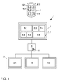
- FIGS. 1 and 2 an embodiment of the device 1 according to the invention and an arrangement of the device 1 according to the invention in a vehicle 7 will be explained.
- the device 1 comprises a first user device 2, which in particular comprises a first display device arranged in the vehicle 7.
- the first user device 2 has a first display area 2.1, on which a plurality of graphical objects 6.1 to 6.6 can be displayed.
- the graphical objects 6.1 to 6.6 are in particular widget objects.
- the widget objects 6.1 to 6.6 support the user in the control of devices of the vehicle 7. In this case, each of the widget objects 6.1 to 6.6 is assigned to a vehicle function.
- a detection unit 8 is further arranged, which is designed as a touch-sensitive surface.
- the device 1 may also comprise a proximity detection unit, via which approaches of an actuating element to the display surface 2.1 can be detected.
- the first user device 2 is arranged in the center console of the vehicle 7 and represents, for example, the infotainment system of the vehicle 7.
- the device 1 has a second user device 3, which is the combination instrument of the vehicle 7.
- the combination instrument 3 also includes a display surface 3.1.
- the display surface 3.1 is provided separately from the display surface 2.1.
- the device 1 also has other user devices 18 and 19.
- the user device 18 is a display device arranged in a headrest. This serves to provide the vehicle occupants in the back of the vehicle 7 entertainment.
- a display device can be arranged in each headrest.
- the display devices in the headrests are also referred to as "Rear Seat Entertainment" RSE.
- the user device 19 is a head-up display that can generate a display area on the driver's side of the vehicle 7 in the windshield.
- the device 1 comprises an interface 10, via which a third user device 4 can be coupled to the device 1.
- the third user device 4 is, for example, a smartphone or a tablet computer of a vehicle occupant.
- the interface 10 may be configured, for example, as a Bluetooth interface.
- the third user device 4 also has a Bluetooth interface so that it can be coupled to the first user device 2. Through the coupling, the user receives access to the third user device 4 via the first user device 2.
- the third user device 4 also has a display area 4.1 on which graphical objects 9.1 to 9.6, which can also be widget objects, are displayed.
- the first user device 2 is connected via a control unit 5 to the second user device 3 and the other user devices 18 and 19. Furthermore, the interface 10 is integrated in the control unit 5, so that the display surfaces All user devices 2, 3, 4, 18 and 19 can be controlled via the control unit 5.
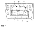
- FIG. 3 An example of a main display, which is also referred to as a home screen, is explained on the first display area 2.1, that is to say the display area 2.1 of the first user device 2, at the beginning of the method according to the invention.
- the home screen is displayed whenever it has been detected that the vehicle 7 and thus the first user device 2 have been started.
- the widget objects 6.1 to 6.6 are displayed in full screen mode on the display area 2.1 in the home screen.
- the full-screen mode represents the first area of the display area 2.1.
- the widget objects 6.1 and 6.6 display data on the weather situation.
- the widget object 6.2 displays data for climate adjustment within the vehicle 7.
- the widget object 6.3 is assigned to the media function of the vehicle 7 and displays the currently playing music track.
- the widget object 6.4 is assigned to the communication function of the vehicle 7. It displays a "Meet Me" application where the user is shown which contact from the contact list of the phone book is in which location and for how long. Furthermore, a bar 11 is displayed for each contact listed, indicating the remaining time that the contact is at the location.
- Widget 6.5 has no content associated with it. The user can assign content to widget object 6.5 at will.
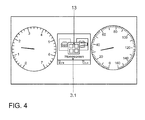
- the display surface 3.1 is located in the combination instrument 3 between a speed and speed indicator.
- the access to the display surface by the user in the combination instrument 3 is limited due to their position in the direction of travel in front of the steering wheel of the vehicle 7.
- the user can control the display on the display surface 3.1 of the combination instrument 3 via a multifunction steering wheel.
- the possibilities are limited in particular by the number of controls that are installed in the multifunction steering wheel.
- the user can configure a home screen 13 for the combination instrument 3 via the first user device 2. This is then displayed in an overview display or in a full-screen display on the display surface 3.1 of the combination instrument 3.
- FIGS. 5 and 6 further details of the embodiment of the device according to the invention and a first embodiment of the method according to the invention will be explained.
- the main display of FIG. 3 is then automatically displayed on the display area 2.1 of the first user device 2.
- the user touches the touch-sensitive surface, ie the detection unit 8, with a fingertip 12 at a point of contact at a location of the widget object 6.3.
- the touch is detected.
- a second area 14 is displayed on the display surface 2.1, with which the widget object 6.3 can be linked.
- the second region 14 is in turn divided into subregions 14.1 to 14.4.
- a graphical object is represented, which represents the combination instrument 3. This makes it clear to the user that he can add the widget object 6.3 to the home screen 13 of the combination instrument 3 by means of an operating action.
- the first area is shown reduced in size.
- the second area 14 may also overlap the full screen mode.
- the widget object 6.3 can be linked to the second area 14 by means of a drag-and-drop operator action. To do this, the user drags the widget object 6.3 e.g. into subarea 14.3.
- the widget object 6.3 is not removed from its original position on the first display area 2.1.
- the widget object 6.3 should continue to be displayed on the home screen of the first display area 2.1. Rather, the touch, which corresponds to a long press, displays a further graphical object 6.3 'on the display area 2.1, which represents the widget object 6.3 and which is drawn into the subarea 14.3.
- the graphical object 6.3 ' is located in the subarea 14.3, the user releases the graphic object 6.3'.
- the widget object 6.3 is added to the home screen 13 of the combination instrument 3. This in turn means that the user can also operate the function assigned to the widget object 6.3 via the combination instrument 3.
- the widget object 6.3 can actually be dragged from its original position into the subarea 14.3. Then the widget object 6.3 is no longer displayed on the first display area 2.1.
- the widget object 6.3 which has been added to the home screen 13 of the combination instrument 3, may have a different configuration than the display surface 2.1 due to the limited space on the display surface 3.1 for the combination instrument 3.
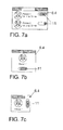
- FIGS. 7a and 7b show examples of the widget object 6.4, as it can be displayed on the first display area 2.1.
- the size of the widget object 6.4 and the abundance of information displayed therein depends on the specifications of the user. This in Figure 7a shown example of the widget object 6.4 shows more information and is therefore designed larger than that in FIG. 7b example shown.
- a widget object 6.4 with small dimensions and therefore with correspondingly little information content is advantageous since the display area 3.1 of the combination instrument 3 generally provides even small dimensions. As a rule, information is not used in favor of clarity.
- Such a widget object 6.4 is in FIG. 7c shown.
- FIG. 8 shows a display on the display area 3.1 with the widget object 6.4 integrated in the display. The information that is displayed is pleasantly visible to the user.
- FIG. 9 an example of a display is shown on the display area 2.1, by means of which the various home screens of the display surfaces of the user devices 3, 18 and 19 can be configured.
- each area 16.1 to 16.4 is displayed on the display area 2.1, each area 16.1 to 16.4 being associated with a user device 3, 18, 19 and 4.
- the areas 16.1 to 16.4 can be designed as buttons, via which the desired user device 3, 18, 19 or 4 can be selected.
- no third user device 4 is coupled to the first user device 2.
- the area 16.4 provided for the third user device 4 is then greyed out, for example, and can not be selected.
- the button 16.1 associated with the combination instrument 3 is selected. This is highlighted. Furthermore, the home screen 13 of the combination instrument 3 is displayed on the first display surface 2.1 of the first user device 2. This includes the widget objects 6.2, 6.3, 6.5, 6.7, 6.8 and 6.9.
- buttons 15.5, 15.8 and 15.9 are displayed, which are assigned to the widget objects 6.5, 6.8 and 6.9 accordingly.
- the fields 15.5, 15.8 and 15.9 display buttons 17.1 and 17.2. If the user presses the button 17.1 of, for example, the field 15.5, the widget object 6.5 is removed from the home screen 13 of the combination instrument 3. If the user presses the button 17.2 of the graphical object 15.5, another window is opened, via which the user can make settings for the widget object 6.5. In this case, for example, he can specify which information is to be displayed in the widget object 6.5 on the display surface 3.1 of the combination instrument 3.
- the widget object 6.8 or 6.9 is removed from the home screen 13 of the combination instrument 3 when the user presses the button 16.1 of the field 15.8 or 15.9.
- Settings for the widget objects 6.8 or 6.9 can be made by the user when pressing the button 17.2 of the field 15.8 or 15.9.
- the user can display additional fields associated with widget object 6.1 through 6.4, and 6.6 and 6.7.
- the widget objects 6.1 to 6.4, and 6.6 and 6.7 can be removed or edited from the homescreen in the same way as the widget objects 6.5, 6.8 and 6.9.
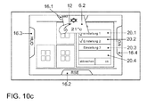
- FIGS. 10a to 10c a further embodiment of the method according to the invention will be explained.
- the areas 16.1 to 16.4, which are assigned to the user devices 3, 18, 19 and 4 are again displayed on the four sides of the display area 2.1.
- the display is on the display area 2.1 in an edit mode, ie in a mode in which the settings for the widget objects 6.1 to 6.9 can be changed.
- the settings for the widget object 6.2 are displayed and can be edited by the user. For example, in the previous example, the user has pressed a button 17.2 of a field which is assigned to the widget object 6.2.
- buttons 20.1 to 20.3 as well as a display field 20.4 are displayed. If the user presses one of the buttons 20.1 to 20.3, the settings for the widget object 6.2 or the settings for the function assigned to the widget object 6.2 are set with the actuated bottom surface 20.1 to 20.3. In the present example, the user has pressed the buttons 20.1 and 20.2. In the display field 20.4, for example, explanations are given to the selected settings 20.1 and 20.2.
- the user remains with his fingertip 12 on the widget object 6.2 and pulls it in the direction of the area 16.1.
- the widget object 6.2 is therefore to be added to the home screen 13 of the combination instrument 3.
- the widget object becomes 6.2, as in FIG. 10c shown pivoted in perspective about an axis. This gives the user the visual impression that he pushes the widget object 6.2 into the area 16.1. If the user has pushed the widget object 6.2 completely into the area 16.1, it disappears from the display of the display area 2.1.
- the widget object 6.2 can also only be copied onto the home screen 13 of the combination instrument 3 by the operating action just described. The widget object 6.2 then remains on the display area 2.1 and is only copied to the display area 3.1.
- a three-dimensional animation for displaying the insertion of the widget object 6.2 into the area 16.1 can also be used.
- the third user device 4 is coupled to the first user device 2 via the interface 10. This gives the user access to the third user device 4.
- the area 16.4 assigned to the third user device 4 is then no longer greyed out and can also be selected.
- the third user device 4 When the third user device 4 is coupled to the first user device 2, it is treated as one of the in-vehicle user devices 3, 18, and 19. All the operator actions and procedures possible for an in-vehicle user device 3, 18, or 19 are then also for the third User device 4 possible.
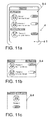
- FIG. 11 a a display is displayed on the display area 4.1 as displayed when the user has opened the "Meet Me” application.
- the "Meet Me” application before being opened, was displayed on the third user device 4 via the widget object 9.4 on the home screen of the third user device 4.
- the home screen of the third user device 4 is displayed on the display surface 2.1 of the first user device 2.
- Each of the widget objects 9.1 to 9.6 can then be accessed via the procedures as described with respect to the FIGS. 5 and 6 and 10a to 10c be integrated into any home screen of a user device 2, 3, 18 or 19.
- Widget objects 9.4 are shown as they can be displayed on the display area 2.1 of the first user device 2. These correspond to the Embodiments of the widget object 6.4 from the FIGS. 7a and 7b ,
- the display within the widget objects 9.4 can be changed by various operator actions. For example, a scrolling in the widget object 9.4 can be generated by swiping gestures. Scrolling then allows further entries, which are not displayed on the home screen of the first user device 2 due to the reduced information content of the widget object 9.4, to be displayed one after the other. In this case, a vertical or a horizontal scroll can be generated by swiping gestures.
- the home screen can be, for example, the home screen, as in FIG. 3 is shown.
- FIG. 11c shows an example of an embodiment of the widget object 9.4 for the display area 3.1 in the combination instrument 3. This corresponds to the example of the widget object 6.4 off FIG. 7c , The widget object 9.4 can then be operated via the multifunction steering wheel.
- FIG. 11d shows an example of a widget object 9.4 as it can be displayed on the display area 3.1.
- FIG. 11e is an example of an ad on the display canvas 3.1, with the widget object 9.4 off FIG. 11d is integrated into the home screen 13 of the display surface 3.1 of the combination instrument 3.
- a so-called mirror link can be produced.
- the function which is assigned to the widget object 9.4 on the smartphone 4 can be operated via the first operating device 2.
- the function itself is not integrated into the vehicle 7, but remains on the third user device 4. This allows the user to bring functions that are not present in the vehicle 7 via an external device in the vehicle 7 and this easy and quick to use there, without being distracted from the road.
- the present invention describes a management system that can configure home screens on various display surfaces within the vehicle 7 and also on display surfaces of external devices coupled to the vehicle 7. Each vehicle occupant can perform the procedure.
Applications Claiming Priority (1)
| Application Number | Priority Date | Filing Date | Title |
|---|---|---|---|
| DE102014206047.8A DE102014206047A1 (de) | 2014-03-31 | 2014-03-31 | Verfahren und Vorrichtung zum Bereitstellen einer graphischen Benutzerschnittstelle in einem Fahrzeug |
Publications (2)
| Publication Number | Publication Date |
|---|---|
| EP2927791A1 true EP2927791A1 (fr) | 2015-10-07 |
| EP2927791B1 EP2927791B1 (fr) | 2019-05-08 |
Family
ID=52692443
Family Applications (1)
| Application Number | Title | Priority Date | Filing Date |
|---|---|---|---|
| EP15158648.4A Active EP2927791B1 (fr) | 2014-03-31 | 2015-03-11 | Procédé et dispositif de préparation d'une interface utilisateur graphique dans un véhicule |
Country Status (3)
| Country | Link |
|---|---|
| EP (1) | EP2927791B1 (fr) |
| DE (1) | DE102014206047A1 (fr) |
| ES (1) | ES2733005T3 (fr) |
Cited By (9)
| Publication number | Priority date | Publication date | Assignee | Title |
|---|---|---|---|---|
| DE102016114669A1 (de) * | 2016-08-08 | 2018-02-08 | Volkswagen Aktiengesellschaft | Verfahren und Bedienvorrichtung zum Bedienen einer Einrichtung |
| EP3324280A1 (fr) | 2016-11-16 | 2018-05-23 | Seat, S.A. | Procédé pour configurer un système d'affichage graphique |
| WO2019020883A1 (fr) | 2017-07-28 | 2019-01-31 | Psa Automobiles Sa | Dispositif pour fournir une interface graphique comptant des widgets dans un véhicule |
| WO2019020884A1 (fr) | 2017-07-28 | 2019-01-31 | Psa Automobiles Sa | Dispositif pour fournir une interface graphique dans un véhicule avec au moins un widget réglementaire |
| FR3069675A1 (fr) * | 2017-07-28 | 2019-02-01 | Psa Automobiles Sa | Dispositif pour fournir une interface graphique comportant des pages de widgets dans un vehicule. |
| FR3096019A1 (fr) * | 2019-05-14 | 2020-11-20 | Psa Automobiles Sa | Procédé et système de contrôle d’affichage dans un véhicule |
| WO2021004682A1 (fr) * | 2019-07-08 | 2021-01-14 | Volkswagen Aktiengesellschaft | Procédé pour faire fonctionner un système de commande utilisateur dans un véhicule et système de commande utilisateur dans un véhicule |
| US11230189B2 (en) | 2019-03-29 | 2022-01-25 | Honda Motor Co., Ltd. | System and method for application interaction on an elongated display screen |
| CN114579003A (zh) * | 2022-03-03 | 2022-06-03 | 阿维塔科技(重庆)有限公司 | 一种车机屏的操作方法及相关组件 |
Families Citing this family (2)
| Publication number | Priority date | Publication date | Assignee | Title |
|---|---|---|---|---|
| DE102016011739A1 (de) | 2016-09-28 | 2018-03-29 | Daimler Ag | Steuerung einer funktionalen Verbindung zwischen einem Infotainmentsystem eines Fahrzeugs und einer mobilen Einheit |
| DE102019209710B4 (de) * | 2019-07-02 | 2023-10-12 | Volkswagen Aktiengesellschaft | Bediensystem umfassend ein Kraftfahrzeug mit einer Bedienvorrichtung |
Citations (6)
| Publication number | Priority date | Publication date | Assignee | Title |
|---|---|---|---|---|
| DE102008028392A1 (de) * | 2008-06-13 | 2009-12-17 | Volkswagen Ag | Anzeigesystem für ein mit einem Kombinationsinstrument ausgestattetes Kraftahrzeug |
| DE102009036371A1 (de) * | 2009-08-06 | 2011-04-07 | Volkswagen Ag | Verfahren und Vorrichtung zum Bereitstellen einer Benutzerschnittstelle |
| WO2011042355A1 (fr) | 2009-10-08 | 2011-04-14 | Bayerische Motoren Werke Aktiengesellschaft | Procédé d'intégration d'un composant dans un système d'information d'un véhicule |
| WO2012110021A2 (fr) | 2011-02-17 | 2012-08-23 | Volkswagen Aktiengesellschaft | Procédé et dispositif pour l'affichage d'états de fonctionnement de dispositifs du véhicule |
| DE102011077429A1 (de) | 2011-06-10 | 2012-12-27 | Bayerische Motoren Werke Aktiengesellschaft | Benutzervorrichtung und System |
| DE102012009021A1 (de) * | 2012-05-05 | 2013-11-07 | Volkswagen Aktiengesellschaft | Verfahren zum Übertragen von Daten von einem mobilen Endgerät zu einem Steuergerät eines Kraftfahrzeuges und Steuergerät |
Family Cites Families (4)
| Publication number | Priority date | Publication date | Assignee | Title |
|---|---|---|---|---|
| DE102008061989B4 (de) * | 2008-12-12 | 2018-06-28 | Volkswagen Ag | Verfahren und Vorrichtung zum Steuern einer optischen und/oder akustischen Ausgabe in einem Fahrzeug |
| DE102011112383B4 (de) * | 2011-09-02 | 2019-06-13 | Volkswagen Aktiengesellschaft | Kombiinstrument für ein Fahrzeug, Fahrzeug mit einem Kombiinstrument und System umfassend ein Fahrzeug und eine mobile Vorrichtung |
| DE102011112447A1 (de) * | 2011-09-03 | 2013-03-07 | Volkswagen Aktiengesellschaft | Verfahren und Anordnung zum Bereitstellen einer graphischen Nutzerschnittstelle, insbesondere in einem Fahrzeug |
| DE102011116175B4 (de) * | 2011-10-14 | 2015-03-26 | Volkswagen Aktiengesellschaft | Verfahren und Vorrichtung zum Bereitstellen einer Nutzerschnittstelle, insbesondere in einem Fahrzeug |
-
2014
- 2014-03-31 DE DE102014206047.8A patent/DE102014206047A1/de not_active Withdrawn
-
2015
- 2015-03-11 ES ES15158648T patent/ES2733005T3/es active Active
- 2015-03-11 EP EP15158648.4A patent/EP2927791B1/fr active Active
Patent Citations (6)
| Publication number | Priority date | Publication date | Assignee | Title |
|---|---|---|---|---|
| DE102008028392A1 (de) * | 2008-06-13 | 2009-12-17 | Volkswagen Ag | Anzeigesystem für ein mit einem Kombinationsinstrument ausgestattetes Kraftahrzeug |
| DE102009036371A1 (de) * | 2009-08-06 | 2011-04-07 | Volkswagen Ag | Verfahren und Vorrichtung zum Bereitstellen einer Benutzerschnittstelle |
| WO2011042355A1 (fr) | 2009-10-08 | 2011-04-14 | Bayerische Motoren Werke Aktiengesellschaft | Procédé d'intégration d'un composant dans un système d'information d'un véhicule |
| WO2012110021A2 (fr) | 2011-02-17 | 2012-08-23 | Volkswagen Aktiengesellschaft | Procédé et dispositif pour l'affichage d'états de fonctionnement de dispositifs du véhicule |
| DE102011077429A1 (de) | 2011-06-10 | 2012-12-27 | Bayerische Motoren Werke Aktiengesellschaft | Benutzervorrichtung und System |
| DE102012009021A1 (de) * | 2012-05-05 | 2013-11-07 | Volkswagen Aktiengesellschaft | Verfahren zum Übertragen von Daten von einem mobilen Endgerät zu einem Steuergerät eines Kraftfahrzeuges und Steuergerät |
Cited By (15)
| Publication number | Priority date | Publication date | Assignee | Title |
|---|---|---|---|---|
| US10649654B2 (en) | 2016-08-08 | 2020-05-12 | Volkswagen Aktiengesellschaft | Device and method for operating a device |
| US10921982B2 (en) | 2016-08-08 | 2021-02-16 | Volkswagen Aktiengesellschaft | Device and method for operating a device |
| DE102016114669A1 (de) * | 2016-08-08 | 2018-02-08 | Volkswagen Aktiengesellschaft | Verfahren und Bedienvorrichtung zum Bedienen einer Einrichtung |
| EP3324280A1 (fr) | 2016-11-16 | 2018-05-23 | Seat, S.A. | Procédé pour configurer un système d'affichage graphique |
| WO2019020884A1 (fr) | 2017-07-28 | 2019-01-31 | Psa Automobiles Sa | Dispositif pour fournir une interface graphique dans un véhicule avec au moins un widget réglementaire |
| FR3069674A1 (fr) * | 2017-07-28 | 2019-02-01 | Psa Automobiles Sa | Dispositif pour fournir une interface graphique dans un vehicule avec au moins un widget reglementaire. |
| FR3069675A1 (fr) * | 2017-07-28 | 2019-02-01 | Psa Automobiles Sa | Dispositif pour fournir une interface graphique comportant des pages de widgets dans un vehicule. |
| CN110945466A (zh) * | 2017-07-28 | 2020-03-31 | 标致雪铁龙汽车股份有限公司 | 用于在车辆中提供包括控件的图形界面的装置 |
| CN110998502A (zh) * | 2017-07-28 | 2020-04-10 | 标致雪铁龙汽车股份有限公司 | 具有至少一个规定控件的在车辆中提供图形界面的装置 |
| FR3069676A1 (fr) * | 2017-07-28 | 2019-02-01 | Psa Automobiles Sa | Dispositif pour fournir une interface graphique comptant des widgets dans un vehicule. |
| WO2019020883A1 (fr) | 2017-07-28 | 2019-01-31 | Psa Automobiles Sa | Dispositif pour fournir une interface graphique comptant des widgets dans un véhicule |
| US11230189B2 (en) | 2019-03-29 | 2022-01-25 | Honda Motor Co., Ltd. | System and method for application interaction on an elongated display screen |
| FR3096019A1 (fr) * | 2019-05-14 | 2020-11-20 | Psa Automobiles Sa | Procédé et système de contrôle d’affichage dans un véhicule |
| WO2021004682A1 (fr) * | 2019-07-08 | 2021-01-14 | Volkswagen Aktiengesellschaft | Procédé pour faire fonctionner un système de commande utilisateur dans un véhicule et système de commande utilisateur dans un véhicule |
| CN114579003A (zh) * | 2022-03-03 | 2022-06-03 | 阿维塔科技(重庆)有限公司 | 一种车机屏的操作方法及相关组件 |
Also Published As
| Publication number | Publication date |
|---|---|
| ES2733005T3 (es) | 2019-11-27 |
| DE102014206047A1 (de) | 2015-10-01 |
| EP2927791B1 (fr) | 2019-05-08 |
Similar Documents
| Publication | Publication Date | Title |
|---|---|---|
| EP2927791B1 (fr) | Procédé et dispositif de préparation d'une interface utilisateur graphique dans un véhicule | |
| WO2014075962A1 (fr) | Système de reproduction d'information et procédé de reproduction d'information | |
| DE102009058145A1 (de) | Bedienverfahren für eine Anzeigevorrichtung eines Fahrzeugs | |
| DE102009036371A1 (de) | Verfahren und Vorrichtung zum Bereitstellen einer Benutzerschnittstelle | |
| EP2930051B1 (fr) | Dispositif et procédé de préparation d'une interface utilisateur graphique dans un véhicule | |
| EP2941685B1 (fr) | Procédé de commande et système de commande pour véhicule | |
| EP2924551B1 (fr) | Procédé et dispositif de préparation d'une interface utilisateur graphique dans un véhicule | |
| EP2425321B1 (fr) | Procédé et dispositif pour afficher de l'information rangée dans des listes | |
| EP2766208B1 (fr) | Procédé d'affichage d'informations en particulier dans un véhicule et système d'affichage pour un véhicule | |
| EP2675648B1 (fr) | Procédé et dispositif pour l'affichage d'états de service de systèmes d'un véhicule et véhicule équipé avec un tel dispositif | |
| EP2987066B1 (fr) | Véhicule à moteur équipé d'un dispositif d'affichage et de commande, et procédé correspondant | |
| DE102011121108B4 (de) | Verfahren und Vorrichtungen zum Ausgeben von Informationen in einem Fahrzeug | |
| EP2930050B1 (fr) | Procédé et dispositif d'affichage d'informations dans un véhicule | |
| DE102008014627B4 (de) | Verfahren zum Betrieb einer mobilen Datenverarbeitungseinrichtung in einem Kraftfahrzeug | |
| DE102014017173A1 (de) | Verfahren zum Steuern von Funktionen einer externen Vorrichtung in einem Fahrzeug | |
| EP1655847B1 (fr) | Dispositif de commande | |
| EP2917062B1 (fr) | Procédé d'affichage d'informations dans un véhicule et dispositif de commande de l'affichage | |
| DE102016220834A1 (de) | Verfahren und Anordnung zur displayübergreifenden Anzeige und/oder Bedienung in einem Fahrzeug | |
| DE102009057082A1 (de) | Verfahren und Vorrichtung zum Anzeigen von Widget-Objekten auf einer Anzeigefläche | |
| EP3033668A1 (fr) | Procédé de fourniture d'un dispositif de commande dans un véhicule et dispositif de commande | |
| DE102014014341B4 (de) | Verfahren zum Betreiben eines Infotainmentsystems eines Kraftfahrzeugs und Infotainmentsystem für ein Kraftfahrzeug | |
| EP2818353A2 (fr) | Dispositif de commande dans un véhicule et procédé de commande de dispositifs de fonctionnement d'un véhicule | |
| EP2927043B1 (fr) | Procédé et système de commande dans un véhicule | |
| DE102014011281A1 (de) | Bediensystem für eine fahrzeugseitige Einrichtung | |
| DE102011116717A1 (de) | Verfahren und Vorrichtungen zur Darstellung von Informations- und Bedienelementen |
Legal Events
| Date | Code | Title | Description |
|---|---|---|---|
| PUAI | Public reference made under article 153(3) epc to a published international application that has entered the european phase |
Free format text: ORIGINAL CODE: 0009012 |
|
| AK | Designated contracting states |
Kind code of ref document: A1 Designated state(s): AL AT BE BG CH CY CZ DE DK EE ES FI FR GB GR HR HU IE IS IT LI LT LU LV MC MK MT NL NO PL PT RO RS SE SI SK SM TR |
|
| AX | Request for extension of the european patent |
Extension state: BA ME |
|
| 17P | Request for examination filed |
Effective date: 20151202 |
|
| RBV | Designated contracting states (corrected) |
Designated state(s): AL AT BE BG CH CY CZ DE DK EE ES FI FR GB GR HR HU IE IS IT LI LT LU LV MC MK MT NL NO PL PT RO RS SE SI SK SM TR |
|
| GRAP | Despatch of communication of intention to grant a patent |
Free format text: ORIGINAL CODE: EPIDOSNIGR1 |
|
| STAA | Information on the status of an ep patent application or granted ep patent |
Free format text: STATUS: GRANT OF PATENT IS INTENDED |
|
| INTG | Intention to grant announced |
Effective date: 20190102 |
|
| GRAS | Grant fee paid |
Free format text: ORIGINAL CODE: EPIDOSNIGR3 |
|
| GRAA | (expected) grant |
Free format text: ORIGINAL CODE: 0009210 |
|
| STAA | Information on the status of an ep patent application or granted ep patent |
Free format text: STATUS: THE PATENT HAS BEEN GRANTED |
|
| AK | Designated contracting states |
Kind code of ref document: B1 Designated state(s): AL AT BE BG CH CY CZ DE DK EE ES FI FR GB GR HR HU IE IS IT LI LT LU LV MC MK MT NL NO PL PT RO RS SE SI SK SM TR |
|
| REG | Reference to a national code |
Ref country code: GB Ref legal event code: FG4D Free format text: NOT ENGLISH |
|
| REG | Reference to a national code |
Ref country code: CH Ref legal event code: EP Ref country code: AT Ref legal event code: REF Ref document number: 1131234 Country of ref document: AT Kind code of ref document: T Effective date: 20190515 |
|
| REG | Reference to a national code |
Ref country code: DE Ref legal event code: R096 Ref document number: 502015008950 Country of ref document: DE Ref country code: IE Ref legal event code: FG4D Free format text: LANGUAGE OF EP DOCUMENT: GERMAN |
|
| REG | Reference to a national code |
Ref country code: NL Ref legal event code: MP Effective date: 20190508 |
|
| REG | Reference to a national code |
Ref country code: LT Ref legal event code: MG4D |
|
| PG25 | Lapsed in a contracting state [announced via postgrant information from national office to epo] |
Ref country code: LT Free format text: LAPSE BECAUSE OF FAILURE TO SUBMIT A TRANSLATION OF THE DESCRIPTION OR TO PAY THE FEE WITHIN THE PRESCRIBED TIME-LIMIT Effective date: 20190508 Ref country code: NL Free format text: LAPSE BECAUSE OF FAILURE TO SUBMIT A TRANSLATION OF THE DESCRIPTION OR TO PAY THE FEE WITHIN THE PRESCRIBED TIME-LIMIT Effective date: 20190508 Ref country code: FI Free format text: LAPSE BECAUSE OF FAILURE TO SUBMIT A TRANSLATION OF THE DESCRIPTION OR TO PAY THE FEE WITHIN THE PRESCRIBED TIME-LIMIT Effective date: 20190508 Ref country code: PT Free format text: LAPSE BECAUSE OF FAILURE TO SUBMIT A TRANSLATION OF THE DESCRIPTION OR TO PAY THE FEE WITHIN THE PRESCRIBED TIME-LIMIT Effective date: 20190908 Ref country code: SE Free format text: LAPSE BECAUSE OF FAILURE TO SUBMIT A TRANSLATION OF THE DESCRIPTION OR TO PAY THE FEE WITHIN THE PRESCRIBED TIME-LIMIT Effective date: 20190508 Ref country code: NO Free format text: LAPSE BECAUSE OF FAILURE TO SUBMIT A TRANSLATION OF THE DESCRIPTION OR TO PAY THE FEE WITHIN THE PRESCRIBED TIME-LIMIT Effective date: 20190808 Ref country code: HR Free format text: LAPSE BECAUSE OF FAILURE TO SUBMIT A TRANSLATION OF THE DESCRIPTION OR TO PAY THE FEE WITHIN THE PRESCRIBED TIME-LIMIT Effective date: 20190508 Ref country code: AL Free format text: LAPSE BECAUSE OF FAILURE TO SUBMIT A TRANSLATION OF THE DESCRIPTION OR TO PAY THE FEE WITHIN THE PRESCRIBED TIME-LIMIT Effective date: 20190508 |
|
| REG | Reference to a national code |
Ref country code: ES Ref legal event code: FG2A Ref document number: 2733005 Country of ref document: ES Kind code of ref document: T3 Effective date: 20191127 |
|
| PG25 | Lapsed in a contracting state [announced via postgrant information from national office to epo] |
Ref country code: BG Free format text: LAPSE BECAUSE OF FAILURE TO SUBMIT A TRANSLATION OF THE DESCRIPTION OR TO PAY THE FEE WITHIN THE PRESCRIBED TIME-LIMIT Effective date: 20190808 Ref country code: GR Free format text: LAPSE BECAUSE OF FAILURE TO SUBMIT A TRANSLATION OF THE DESCRIPTION OR TO PAY THE FEE WITHIN THE PRESCRIBED TIME-LIMIT Effective date: 20190809 Ref country code: RS Free format text: LAPSE BECAUSE OF FAILURE TO SUBMIT A TRANSLATION OF THE DESCRIPTION OR TO PAY THE FEE WITHIN THE PRESCRIBED TIME-LIMIT Effective date: 20190508 Ref country code: LV Free format text: LAPSE BECAUSE OF FAILURE TO SUBMIT A TRANSLATION OF THE DESCRIPTION OR TO PAY THE FEE WITHIN THE PRESCRIBED TIME-LIMIT Effective date: 20190508 |
|
| PG25 | Lapsed in a contracting state [announced via postgrant information from national office to epo] |
Ref country code: EE Free format text: LAPSE BECAUSE OF FAILURE TO SUBMIT A TRANSLATION OF THE DESCRIPTION OR TO PAY THE FEE WITHIN THE PRESCRIBED TIME-LIMIT Effective date: 20190508 Ref country code: DK Free format text: LAPSE BECAUSE OF FAILURE TO SUBMIT A TRANSLATION OF THE DESCRIPTION OR TO PAY THE FEE WITHIN THE PRESCRIBED TIME-LIMIT Effective date: 20190508 Ref country code: SK Free format text: LAPSE BECAUSE OF FAILURE TO SUBMIT A TRANSLATION OF THE DESCRIPTION OR TO PAY THE FEE WITHIN THE PRESCRIBED TIME-LIMIT Effective date: 20190508 Ref country code: CZ Free format text: LAPSE BECAUSE OF FAILURE TO SUBMIT A TRANSLATION OF THE DESCRIPTION OR TO PAY THE FEE WITHIN THE PRESCRIBED TIME-LIMIT Effective date: 20190508 Ref country code: RO Free format text: LAPSE BECAUSE OF FAILURE TO SUBMIT A TRANSLATION OF THE DESCRIPTION OR TO PAY THE FEE WITHIN THE PRESCRIBED TIME-LIMIT Effective date: 20190508 |
|
| REG | Reference to a national code |
Ref country code: DE Ref legal event code: R097 Ref document number: 502015008950 Country of ref document: DE |
|
| PG25 | Lapsed in a contracting state [announced via postgrant information from national office to epo] |
Ref country code: SM Free format text: LAPSE BECAUSE OF FAILURE TO SUBMIT A TRANSLATION OF THE DESCRIPTION OR TO PAY THE FEE WITHIN THE PRESCRIBED TIME-LIMIT Effective date: 20190508 |
|
| PLBE | No opposition filed within time limit |
Free format text: ORIGINAL CODE: 0009261 |
|
| STAA | Information on the status of an ep patent application or granted ep patent |
Free format text: STATUS: NO OPPOSITION FILED WITHIN TIME LIMIT |
|
| PG25 | Lapsed in a contracting state [announced via postgrant information from national office to epo] |
Ref country code: TR Free format text: LAPSE BECAUSE OF FAILURE TO SUBMIT A TRANSLATION OF THE DESCRIPTION OR TO PAY THE FEE WITHIN THE PRESCRIBED TIME-LIMIT Effective date: 20190508 |
|
| 26N | No opposition filed |
Effective date: 20200211 |
|
| PG25 | Lapsed in a contracting state [announced via postgrant information from national office to epo] |
Ref country code: PL Free format text: LAPSE BECAUSE OF FAILURE TO SUBMIT A TRANSLATION OF THE DESCRIPTION OR TO PAY THE FEE WITHIN THE PRESCRIBED TIME-LIMIT Effective date: 20190508 |
|
| PG25 | Lapsed in a contracting state [announced via postgrant information from national office to epo] |
Ref country code: SI Free format text: LAPSE BECAUSE OF FAILURE TO SUBMIT A TRANSLATION OF THE DESCRIPTION OR TO PAY THE FEE WITHIN THE PRESCRIBED TIME-LIMIT Effective date: 20190508 |
|
| PG25 | Lapsed in a contracting state [announced via postgrant information from national office to epo] |
Ref country code: MC Free format text: LAPSE BECAUSE OF FAILURE TO SUBMIT A TRANSLATION OF THE DESCRIPTION OR TO PAY THE FEE WITHIN THE PRESCRIBED TIME-LIMIT Effective date: 20190508 |
|
| REG | Reference to a national code |
Ref country code: CH Ref legal event code: PL |
|
| REG | Reference to a national code |
Ref country code: BE Ref legal event code: MM Effective date: 20200331 |
|
| PG25 | Lapsed in a contracting state [announced via postgrant information from national office to epo] |
Ref country code: LU Free format text: LAPSE BECAUSE OF NON-PAYMENT OF DUE FEES Effective date: 20200311 |
|
| PG25 | Lapsed in a contracting state [announced via postgrant information from national office to epo] |
Ref country code: LI Free format text: LAPSE BECAUSE OF NON-PAYMENT OF DUE FEES Effective date: 20200331 Ref country code: IE Free format text: LAPSE BECAUSE OF NON-PAYMENT OF DUE FEES Effective date: 20200311 Ref country code: CH Free format text: LAPSE BECAUSE OF NON-PAYMENT OF DUE FEES Effective date: 20200331 |
|
| PG25 | Lapsed in a contracting state [announced via postgrant information from national office to epo] |
Ref country code: BE Free format text: LAPSE BECAUSE OF NON-PAYMENT OF DUE FEES Effective date: 20200331 |
|
| REG | Reference to a national code |
Ref country code: AT Ref legal event code: MM01 Ref document number: 1131234 Country of ref document: AT Kind code of ref document: T Effective date: 20200311 |
|
| PG25 | Lapsed in a contracting state [announced via postgrant information from national office to epo] |
Ref country code: AT Free format text: LAPSE BECAUSE OF NON-PAYMENT OF DUE FEES Effective date: 20200311 |
|
| PG25 | Lapsed in a contracting state [announced via postgrant information from national office to epo] |
Ref country code: MT Free format text: LAPSE BECAUSE OF FAILURE TO SUBMIT A TRANSLATION OF THE DESCRIPTION OR TO PAY THE FEE WITHIN THE PRESCRIBED TIME-LIMIT Effective date: 20190508 Ref country code: CY Free format text: LAPSE BECAUSE OF FAILURE TO SUBMIT A TRANSLATION OF THE DESCRIPTION OR TO PAY THE FEE WITHIN THE PRESCRIBED TIME-LIMIT Effective date: 20190508 |
|
| PG25 | Lapsed in a contracting state [announced via postgrant information from national office to epo] |
Ref country code: MK Free format text: LAPSE BECAUSE OF FAILURE TO SUBMIT A TRANSLATION OF THE DESCRIPTION OR TO PAY THE FEE WITHIN THE PRESCRIBED TIME-LIMIT Effective date: 20190508 Ref country code: IS Free format text: LAPSE BECAUSE OF FAILURE TO SUBMIT A TRANSLATION OF THE DESCRIPTION OR TO PAY THE FEE WITHIN THE PRESCRIBED TIME-LIMIT Effective date: 20190908 |
|
| PGFP | Annual fee paid to national office [announced via postgrant information from national office to epo] |
Ref country code: FR Payment date: 20230323 Year of fee payment: 9 |
|
| PGFP | Annual fee paid to national office [announced via postgrant information from national office to epo] |
Ref country code: IT Payment date: 20230321 Year of fee payment: 9 Ref country code: GB Payment date: 20230321 Year of fee payment: 9 Ref country code: DE Payment date: 20230331 Year of fee payment: 9 |
|
| P01 | Opt-out of the competence of the unified patent court (upc) registered |
Effective date: 20230523 |
|
| PGFP | Annual fee paid to national office [announced via postgrant information from national office to epo] |
Ref country code: ES Payment date: 20230424 Year of fee payment: 9 |