EP2927518A1 - Flocked driving cable and manufacturing method thereof - Google Patents
Flocked driving cable and manufacturing method thereof Download PDFInfo
- Publication number
- EP2927518A1 EP2927518A1 EP14172369.2A EP14172369A EP2927518A1 EP 2927518 A1 EP2927518 A1 EP 2927518A1 EP 14172369 A EP14172369 A EP 14172369A EP 2927518 A1 EP2927518 A1 EP 2927518A1
- Authority
- EP
- European Patent Office
- Prior art keywords
- electric field
- raw
- sunroof
- manufacturing
- field chamber
- Prior art date
- Legal status (The legal status is an assumption and is not a legal conclusion. Google has not performed a legal analysis and makes no representation as to the accuracy of the status listed.)
- Withdrawn
Links
- 238000004519 manufacturing process Methods 0.000 title claims abstract description 32
- 230000005684 electric field Effects 0.000 claims abstract description 42
- 239000000853 adhesive Substances 0.000 claims abstract description 18
- 230000001070 adhesive effect Effects 0.000 claims abstract description 18
- 239000012790 adhesive layer Substances 0.000 claims abstract description 11
- 238000007664 blowing Methods 0.000 claims description 5
- 238000000034 method Methods 0.000 description 4
- 230000008569 process Effects 0.000 description 4
- 230000008901 benefit Effects 0.000 description 2
- 230000000694 effects Effects 0.000 description 2
- 238000004804 winding Methods 0.000 description 2
- 229910000831 Steel Inorganic materials 0.000 description 1
- 238000007792 addition Methods 0.000 description 1
- 230000008859 change Effects 0.000 description 1
- 230000008878 coupling Effects 0.000 description 1
- 238000010168 coupling process Methods 0.000 description 1
- 238000005859 coupling reaction Methods 0.000 description 1
- 238000009434 installation Methods 0.000 description 1
- 238000012986 modification Methods 0.000 description 1
- 230000004048 modification Effects 0.000 description 1
- 239000010959 steel Substances 0.000 description 1
- 238000006467 substitution reaction Methods 0.000 description 1
Images



Classifications
-
- B—PERFORMING OPERATIONS; TRANSPORTING
- B60—VEHICLES IN GENERAL
- B60J—WINDOWS, WINDSCREENS, NON-FIXED ROOFS, DOORS, OR SIMILAR DEVICES FOR VEHICLES; REMOVABLE EXTERNAL PROTECTIVE COVERINGS SPECIALLY ADAPTED FOR VEHICLES
- B60J7/00—Non-fixed roofs; Roofs with movable panels, e.g. rotary sunroofs
- B60J7/02—Non-fixed roofs; Roofs with movable panels, e.g. rotary sunroofs of sliding type, e.g. comprising guide shoes
- B60J7/04—Non-fixed roofs; Roofs with movable panels, e.g. rotary sunroofs of sliding type, e.g. comprising guide shoes with rigid plate-like element or elements, e.g. open roofs with harmonica-type folding rigid panels
- B60J7/043—Sunroofs e.g. sliding above the roof
-
- B—PERFORMING OPERATIONS; TRANSPORTING
- B05—SPRAYING OR ATOMISING IN GENERAL; APPLYING FLUENT MATERIALS TO SURFACES, IN GENERAL
- B05D—PROCESSES FOR APPLYING FLUENT MATERIALS TO SURFACES, IN GENERAL
- B05D1/00—Processes for applying liquids or other fluent materials
- B05D1/16—Flocking otherwise than by spraying
-
- B—PERFORMING OPERATIONS; TRANSPORTING
- B05—SPRAYING OR ATOMISING IN GENERAL; APPLYING FLUENT MATERIALS TO SURFACES, IN GENERAL
- B05B—SPRAYING APPARATUS; ATOMISING APPARATUS; NOZZLES
- B05B5/00—Electrostatic spraying apparatus; Spraying apparatus with means for charging the spray electrically; Apparatus for spraying liquids or other fluent materials by other electric means
-
- B—PERFORMING OPERATIONS; TRANSPORTING
- B05—SPRAYING OR ATOMISING IN GENERAL; APPLYING FLUENT MATERIALS TO SURFACES, IN GENERAL
- B05C—APPARATUS FOR APPLYING FLUENT MATERIALS TO SURFACES, IN GENERAL
- B05C19/00—Apparatus specially adapted for applying particulate materials to surfaces
- B05C19/001—Flocking
- B05C19/002—Electrostatic flocking
-
- B—PERFORMING OPERATIONS; TRANSPORTING
- B05—SPRAYING OR ATOMISING IN GENERAL; APPLYING FLUENT MATERIALS TO SURFACES, IN GENERAL
- B05D—PROCESSES FOR APPLYING FLUENT MATERIALS TO SURFACES, IN GENERAL
- B05D7/00—Processes, other than flocking, specially adapted for applying liquids or other fluent materials to particular surfaces or for applying particular liquids or other fluent materials
- B05D7/20—Processes, other than flocking, specially adapted for applying liquids or other fluent materials to particular surfaces or for applying particular liquids or other fluent materials to wires
-
- D—TEXTILES; PAPER
- D07—ROPES; CABLES OTHER THAN ELECTRIC
- D07B—ROPES OR CABLES IN GENERAL
- D07B1/00—Constructional features of ropes or cables
- D07B1/16—Ropes or cables with an enveloping sheathing or inlays of rubber or plastics
-
- D—TEXTILES; PAPER
- D07—ROPES; CABLES OTHER THAN ELECTRIC
- D07B—ROPES OR CABLES IN GENERAL
- D07B7/00—Details of, or auxiliary devices incorporated in, rope- or cable-making machines; Auxiliary apparatus associated with such machines
- D07B7/02—Machine details; Auxiliary devices
- D07B7/14—Machine details; Auxiliary devices for coating or wrapping ropes, cables, or component strands thereof
-
- F—MECHANICAL ENGINEERING; LIGHTING; HEATING; WEAPONS; BLASTING
- F16—ENGINEERING ELEMENTS AND UNITS; GENERAL MEASURES FOR PRODUCING AND MAINTAINING EFFECTIVE FUNCTIONING OF MACHINES OR INSTALLATIONS; THERMAL INSULATION IN GENERAL
- F16C—SHAFTS; FLEXIBLE SHAFTS; ELEMENTS OR CRANKSHAFT MECHANISMS; ROTARY BODIES OTHER THAN GEARING ELEMENTS; BEARINGS
- F16C1/00—Flexible shafts; Mechanical means for transmitting movement in a flexible sheathing
- F16C1/10—Means for transmitting linear movement in a flexible sheathing, e.g. "Bowden-mechanisms"
- F16C1/20—Construction of flexible members moved to and fro in the sheathing
- F16C1/205—Details of the outer surface of the flexible member, e.g. coatings
-
- F—MECHANICAL ENGINEERING; LIGHTING; HEATING; WEAPONS; BLASTING
- F16—ENGINEERING ELEMENTS AND UNITS; GENERAL MEASURES FOR PRODUCING AND MAINTAINING EFFECTIVE FUNCTIONING OF MACHINES OR INSTALLATIONS; THERMAL INSULATION IN GENERAL
- F16C—SHAFTS; FLEXIBLE SHAFTS; ELEMENTS OR CRANKSHAFT MECHANISMS; ROTARY BODIES OTHER THAN GEARING ELEMENTS; BEARINGS
- F16C2326/00—Articles relating to transporting
- F16C2326/01—Parts of vehicles in general
Definitions
- the present invention relates to a sunroof cable unit and a manufacturing method thereof and, more particularly, to a sunroof cable unit, which has an improved configuration and manufacturing process to enhance mass productivity and manufacturing simplicity of products with regard to attachment of piles that may function to minimize noise and friction of a sunroof cable, and a manufacturing method of the sunroof cable unit.
- a sunroof cable unit serves to transmit power to a sunroof of an automobile to enable opening/closing of the sunroof.
- the sunroof cable unit includes a steel core, a stranded wire surrounding the core, a coil helically surrounding the stranded wire and flocked members helically fitted into a groove defined by the coil.
- the present invention has been made in view of the above problems, and it is an object of the present invention to provide a sunroof cable unit, which is capable of minimizing friction between elements used to open or close a sunroof and of achieving reduced manufacturing costs and enhanced mass productivity of products, and a manufacturing method of the sunroof cable unit.
- a sunroof cable unit which is configured to transmit power to a sunroof of an automobile, includes a raw cable including a core extending by a long length in a given directional axis and a coil helically surrounding the core, the coil defining a groove between a pair of neighboring helices, an adhesive layer formed by applying an adhesive to the groove of the raw cable, and a plurality of piles adhered to the adhesive layer by electrostatic force generated in an electric field.
- a manufacturing method of a sunroof cable unit configured to transmit power to a sunroof of an automobile, includes simultaneously transporting a plurality of raw cables to an electric field chamber, wherein each raw cable extends by a long length in a given directional axis, applying an adhesive to a groove defined in each raw cable prior to introducing the raw cables into the electric field chamber, and generating electrostatic force within the electric field chamber in a state in which the plural raw cables are introduced into the electric field chamber, so as to adhere a plurality of piles to the grooves of the plural raw cables to which the adhesive has been applied.
- the manufacturing method of the sunroof cable unit may further include generating an air stream within the electric field chamber using a blowing device to allow the plural piles fed into the electric field chamber to uniformly float within the electric field chamber.
- a pair of electrodes constituting the electric field chamber may be arranged to face each other about the given directional axis, and charges of different polarities may be applied to the pair of electrodes arranged to face each other.
- the raw cables introduced into the electric field chamber may be rotated between electrodes, or the electrodes may be rotated relative to the raw cables.
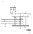
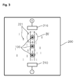
- FIGS. 1 to 3 are reference views for explanation of a manufacturing method of a sunroof cable unit according to one embodiment of the present invention
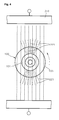
- FIG. 4 is a view for explanation of the adhesion form of piles that are adhered to raw cables by a pair of electrodes according to one embodiment of the present invention.
- the sunroof cable unit serves to transmit power to a sunroof of an automobile.
- the sunroof cable unit is preferably comprised of raw cables 100, an adhesive layer and a plurality of piles 221.
- Each of the raw cables 100 includes a core 101 extending by a long length in a given directional axis and a coil 103 helically surrounding the core 101, the coil 103 defining a groove 105 between a pair of neighboring helices.
- the adhesive layer is formed on a surface of the raw cable 100 as an adhesive is applied to the groove 105 of the raw cable 100.
- application of the adhesive to the raw cable 100 is preferably implemented using an external ejection nozzle (not shown), the disclosure is not limited thereto and various other devices capable of applying an adhesive to the raw cable 100 or forming an adhesive layer on the raw cable 100 may be used.
- the plural piles 221 are adhered to the adhesive layer of the raw cable 100 by electrostatic force E that is generated in an electric field chamber 200.
- the piles 221 are preferably flocked yarns obtained by cutting yarns to a short length, without being limited thereto.
- a plurality of piles is adhered to raw cables at once. Owing to these piles, the present invention may advantageously reduce friction and noise of the sunroof cable unit.
- the electric field chamber 200 is required to adhere the piles 221 to the raw cables 100 to which the adhesive has been applied.
- the electric field chamber 200 which is employed to manufacture the sunroof cable unit according to one embodiment of the present invention, preferably includes a pair of electrodes 210 to generate electrostatic force E in the electric field chamber 200 and a pile feed box 220 to feed the piles 221 to the raw cables 100.
- a blowing device 230 may further be incorporated in the electric field chamber 200, to allow the respective piles 221 to uniformly float in the electric field chamber 200.
- a manufacturing method of a sunroof cable unit relates to the manufacture of a sunroof cable unit that serves to transmit power to a sunroof of an automobile.
- the plural raw cables 100 which extend by a long length in a given directional axis, are simultaneously transported to the electric field chamber 200.
- the adhesive is applied to the groove 105 of each raw cable 100.
- application of the adhesive to the raw cable 100 is preferably implemented using an external ejection nozzle (not shown), the disclosure is not limited thereto and various other devices capable of adhering the adhesive to the raw cable 100 or forming an adhesive layer on the raw cable 100 may be used.
- the plural piles 221 are adhered to the grooves 105 of the raw cables 100 by electrostatic force E generated in the electric field chamber 200. More specifically, when electrostatic force E is generated in the electric field chamber 200 in a state in which the plural piles 221 are introduced into the electric field chamber 200, the piles 221 fed into the electric field chamber 200 are moved by the electrostatic force E in the direction of electrostatic force E. Thereby, the piles 221 are adhered to the raw cables 100, to which the adhesive has been applied, during movement thereof.
- the sunroof cable unit which is capable of reducing noise and friction between elements used to open or close a sunroof, may achieve reduced manufacturing costs and enhanced mass productivity.
- the blowing device 230 serves to generate an air stream within the electric field chamber 200, in order to allow the plural piles 221 fed into the electric field chamber 200 to uniformly float within the electric field chamber 200.
- generating the air stream using the blowing device 230 may ensure circulation of the piles 221 within the electric field chamber 200, which advantageously allows the piles 221 to be efficiently adhered to the raw cables 100.
- the electric field chamber 200 preferably includes the pair of electrodes 210 to generate the electrostatic force E.
- the pair of electrodes 210 is arranged to face each other about a given directional axis and charges of different polarities are applied to the electrodes 210 facing each other.
- FIG. 5 is a view for explanation of the direction of electrostatic force E depending on charges applied to the pair of electrodes.
- the electrodes 210 are arranged to face each other about a given directional axis and charges of different polarities are applied to the electrodes 210 facing each other as described above, as exemplarily shown in FIGS. 2 to 5 , electrostatic force is generated from the positive electrode to the negative electrode.
- the piles 221 fed into the chamber 200 may be adhered to the raw cables 100 in a direction from the positive electrode to the negative electrode or from the negative electrode to the positive electrode. This advantageously allows the piles 221 to be attached to the raw cables 100 in a simplified manner and to be aligned in a given direction.
- electrostatic force E may be applied outward, which causes the piles 221 to be not adhered to the raw cables 100 or the piles 221 to loss their directivity.
- FIG. 6 is a view for explanation of the arrangement of a plurality of raw cables for adhesion of piles thereto according to one embodiment of the present invention.
- the electric field chamber 200 is preferably configured to rotate at least one of the electrodes 210 and the raw cables 100 introduced into the electric field chamber 200 relative to the other one.
- FIG. 7 is a view for explanation of rotation of a pair of electrodes about raw cables according to another embodiment of the present invention.
- the raw cables 100 may be rotated as exemplarily shown in FIG. 4
- the pair of electrodes 210 may be rotated as exemplarily shown in FIG. 7 .
- the pair of electrodes 210 may be radially spaced apart from each other by a constant distance.
- This radial arrangement of the pair of electrodes 210 spaced apart from each other by a constant distance disadvantageously increases required device installation space, but may advantageously increase durability of a device because rotation of the electrodes or the raw cables is unnecessary.
- the present invention has the effect of reducing friction and noise of a sunroof cable unit owing to the fact that a plurality of piles is adhered to a plurality of raw cables at once.
- the present invention has the effect of simplifying a manufacturing process and achieving enhanced mass productivity of products and reduced manufacturing costs.
Landscapes
- Engineering & Computer Science (AREA)
- Mechanical Engineering (AREA)
- Processes Specially Adapted For Manufacturing Cables (AREA)
- Installation Of Indoor Wiring (AREA)
Abstract
Description
- The present invention relates to a sunroof cable unit and a manufacturing method thereof and, more particularly, to a sunroof cable unit, which has an improved configuration and manufacturing process to enhance mass productivity and manufacturing simplicity of products with regard to attachment of piles that may function to minimize noise and friction of a sunroof cable, and a manufacturing method of the sunroof cable unit.
- In general, a sunroof cable unit serves to transmit power to a sunroof of an automobile to enable opening/closing of the sunroof. The sunroof cable unit includes a steel core, a stranded wire surrounding the core, a coil helically surrounding the stranded wire and flocked members helically fitted into a groove defined by the coil.
- Here, to minimize friction between elements used to open or close a sunroof, all conventional sunroof cable units have focused on the configuration or manufacturing method of the flocked members.
- Changes in the configuration and manufacturing method of the flocked members have caused difficulty in forming and increased manufacturing costs because design change with respect to the small-scale member requires a complicated manufacturing process and the like.
- As another solution to minimize friction between elements used to open or close a sunroof, covering the coil with a tube has been proposed.
- However, this conventional solution has several disadvantages, such as difficulty in covering the coil with the tube and an increase in the number of manufacturing processes because additional processes of manufacturing the tube and of coupling the manufactured tube to the coil are necessary.
- Therefore, the present invention has been made in view of the above problems, and it is an object of the present invention to provide a sunroof cable unit, which is capable of minimizing friction between elements used to open or close a sunroof and of achieving reduced manufacturing costs and enhanced mass productivity of products, and a manufacturing method of the sunroof cable unit.
- In accordance with one aspect of the present invention, to accomplish the above and other objects, a sunroof cable unit, which is configured to transmit power to a sunroof of an automobile, includes a raw cable including a core extending by a long length in a given directional axis and a coil helically surrounding the core, the coil defining a groove between a pair of neighboring helices, an adhesive layer formed by applying an adhesive to the groove of the raw cable, and a plurality of piles adhered to the adhesive layer by electrostatic force generated in an electric field.
- In accordance with another aspect of the present invention, a manufacturing method of a sunroof cable unit, configured to transmit power to a sunroof of an automobile, includes simultaneously transporting a plurality of raw cables to an electric field chamber, wherein each raw cable extends by a long length in a given directional axis, applying an adhesive to a groove defined in each raw cable prior to introducing the raw cables into the electric field chamber, and generating electrostatic force within the electric field chamber in a state in which the plural raw cables are introduced into the electric field chamber, so as to adhere a plurality of piles to the grooves of the plural raw cables to which the adhesive has been applied.
- According to one embodiment of the present invention, the manufacturing method of the sunroof cable unit may further include generating an air stream within the electric field chamber using a blowing device to allow the plural piles fed into the electric field chamber to uniformly float within the electric field chamber.
- In addition, according to one embodiment of the present invention, a pair of electrodes constituting the electric field chamber may be arranged to face each other about the given directional axis, and charges of different polarities may be applied to the pair of electrodes arranged to face each other.
- In addition, according to one embodiment of the present invention, the raw cables introduced into the electric field chamber may be rotated between electrodes, or the electrodes may be rotated relative to the raw cables.
- The above and other objects, features and other advantages of the present invention will be more clearly understood from the following detailed description taken in conjunction with the accompanying drawings, in which:
-
FIGS. 1 to 3 are reference views for explanation of a manufacturing method of a sunroof cable unit according to one embodiment of the present invention; -
FIG. 4 is a view for explanation of the adhesion form of piles that are adhered to raw cables by a pair of electrodes according to one embodiment of the present invention; -
FIG. 5 is a view for explanation of the direction of electrostatic force depending on charges applied to a pair of electrodes; -
FIG. 6 is a view for explanation of the arrangement of a plurality of raw cables for adhesion of piles thereto according to one embodiment of the present invention; and -
FIG. 7 is a view for explanation of rotation of a pair of electrodes about raw cables according to another embodiment of the present invention. - Hereinafter, a sunroof cable unit and a manufacturing method thereof according to one embodiment of the present invention will be described with reference to the accompanying drawings.
-
FIGS. 1 to 3 are reference views for explanation of a manufacturing method of a sunroof cable unit according to one embodiment of the present invention, andFIG. 4 is a view for explanation of the adhesion form of piles that are adhered to raw cables by a pair of electrodes according to one embodiment of the present invention. - As exemplarily shown in the drawings, the sunroof cable unit according to one embodiment of the present invention serves to transmit power to a sunroof of an automobile. The sunroof cable unit is preferably comprised of
raw cables 100, an adhesive layer and a plurality ofpiles 221. - Each of the
raw cables 100 includes acore 101 extending by a long length in a given directional axis and acoil 103 helically surrounding thecore 101, thecoil 103 defining agroove 105 between a pair of neighboring helices. - The adhesive layer is formed on a surface of the
raw cable 100 as an adhesive is applied to thegroove 105 of theraw cable 100. Generally, although application of the adhesive to theraw cable 100 is preferably implemented using an external ejection nozzle (not shown), the disclosure is not limited thereto and various other devices capable of applying an adhesive to theraw cable 100 or forming an adhesive layer on theraw cable 100 may be used. - The
plural piles 221 are adhered to the adhesive layer of theraw cable 100 by electrostatic force E that is generated in anelectric field chamber 200. Here, thepiles 221 are preferably flocked yarns obtained by cutting yarns to a short length, without being limited thereto. - According to one embodiment of the present invention, a plurality of piles is adhered to raw cables at once. Owing to these piles, the present invention may advantageously reduce friction and noise of the sunroof cable unit.
- To manufacture the sunroof cable unit as described above, the
electric field chamber 200 is required to adhere thepiles 221 to theraw cables 100 to which the adhesive has been applied. - Meanwhile, the
electric field chamber 200, which is employed to manufacture the sunroof cable unit according to one embodiment of the present invention, preferably includes a pair ofelectrodes 210 to generate electrostatic force E in theelectric field chamber 200 and apile feed box 220 to feed thepiles 221 to theraw cables 100. In addition, a blowingdevice 230 may further be incorporated in theelectric field chamber 200, to allow therespective piles 221 to uniformly float in theelectric field chamber 200. - A manufacturing method of a sunroof cable unit according to one embodiment of the present invention relates to the manufacture of a sunroof cable unit that serves to transmit power to a sunroof of an automobile.
- First, the plural
raw cables 100, which extend by a long length in a given directional axis, are simultaneously transported to theelectric field chamber 200. - Meanwhile, prior to introducing the
raw cables 100 into theelectric field chamber 200, the adhesive is applied to thegroove 105 of eachraw cable 100. Although application of the adhesive to theraw cable 100 is preferably implemented using an external ejection nozzle (not shown), the disclosure is not limited thereto and various other devices capable of adhering the adhesive to theraw cable 100 or forming an adhesive layer on theraw cable 100 may be used. - Thereafter, as exemplarily shown in
FIG. 2 , as the pluralraw cables 100, to which the adhesive has been applied, are introduced into theelectric field chamber 200, theplural piles 221 are adhered to thegrooves 105 of theraw cables 100 by electrostatic force E generated in theelectric field chamber 200. More specifically, when electrostatic force E is generated in theelectric field chamber 200 in a state in which theplural piles 221 are introduced into theelectric field chamber 200, thepiles 221 fed into theelectric field chamber 200 are moved by the electrostatic force E in the direction of electrostatic force E. Thereby, thepiles 221 are adhered to theraw cables 100, to which the adhesive has been applied, during movement thereof. - In this way, according to one embodiment of the present invention, as a result of the
piles 221 being adhered to theraw cables 100 by electrostatic force E, a conventional process of winding high price flocked yarns is unnecessary, which may result in a simplified process and enhanced mass productivity of products. - In addition, according to one embodiment of the present invention, adhering the
plural piles 221 to the pluralraw cables 100 via the adhesive and via the electrostatic force E in theelectric field chamber 200 is possible and, therefore, the sunroof cable unit, which is capable of reducing noise and friction between elements used to open or close a sunroof, may achieve reduced manufacturing costs and enhanced mass productivity. - Moreover, according to one embodiment of the present invention, as is clearly shown in
FIG. 2 , the blowingdevice 230 serves to generate an air stream within theelectric field chamber 200, in order to allow theplural piles 221 fed into theelectric field chamber 200 to uniformly float within theelectric field chamber 200. - As described above, according to one embodiment of the present invention, in consideration of the fact that the fed
piles 221 are not wholly adhered to theraw cables 100 rather being accumulated on the bottom of thechamber 200, generating the air stream using the blowingdevice 230 may ensure circulation of thepiles 221 within theelectric field chamber 200, which advantageously allows thepiles 221 to be efficiently adhered to theraw cables 100. - The
electric field chamber 200 according to one embodiment of the present invention as described above preferably includes the pair ofelectrodes 210 to generate the electrostatic force E. - Preferably, the pair of
electrodes 210 is arranged to face each other about a given directional axis and charges of different polarities are applied to theelectrodes 210 facing each other. -
FIG. 5 is a view for explanation of the direction of electrostatic force E depending on charges applied to the pair of electrodes. - In a case in which the
electrodes 210 are arranged to face each other about a given directional axis and charges of different polarities are applied to theelectrodes 210 facing each other as described above, as exemplarily shown inFIGS. 2 to 5 , electrostatic force is generated from the positive electrode to the negative electrode. In such a state, as exemplarily shown inFIG. 4 , thepiles 221 fed into thechamber 200 may be adhered to theraw cables 100 in a direction from the positive electrode to the negative electrode or from the negative electrode to the positive electrode. This advantageously allows thepiles 221 to be attached to theraw cables 100 in a simplified manner and to be aligned in a given direction. - Assuming that charges of the same polarity are applied to the pair of
electrodes 210, as exemplarily shown inFIG. 5 , electrostatic force E may be applied outward, which causes thepiles 221 to be not adhered to theraw cables 100 or thepiles 221 to loss their directivity. -
FIG. 6 is a view for explanation of the arrangement of a plurality of raw cables for adhesion of piles thereto according to one embodiment of the present invention. - According to one embodiment of the present invention, as exemplarily shown in
FIG. 6 , it is advantageously possible to simultaneously attach thepiles 221 to the pluralraw cables 100. - On the other hand, the
electric field chamber 200 according to another embodiment of the present invention is preferably configured to rotate at least one of theelectrodes 210 and theraw cables 100 introduced into theelectric field chamber 200 relative to the other one. -
FIG. 7 is a view for explanation of rotation of a pair of electrodes about raw cables according to another embodiment of the present invention. - Note that the
raw cables 100 may be rotated as exemplarily shown inFIG. 4 , and the pair ofelectrodes 210 may be rotated as exemplarily shown inFIG. 7 . - When the pair of
electrodes 210 is rotated as exemplarily shown inFIG. 7 , there is an advantage in that thepiles 221 may be uniformly adhered to theraw cables 100 without rotation of the respectiveraw cables 100. - Meanwhile, although the above embodiment of the present invention illustrates rotation of the pair of
electrodes 210, the pair ofelectrodes 210 may be radially spaced apart from each other by a constant distance. This radial arrangement of the pair ofelectrodes 210 spaced apart from each other by a constant distance disadvantageously increases required device installation space, but may advantageously increase durability of a device because rotation of the electrodes or the raw cables is unnecessary. - As is apparent from the above description, the present invention has the effect of reducing friction and noise of a sunroof cable unit owing to the fact that a plurality of piles is adhered to a plurality of raw cables at once.
- In addition, according to one embodiment of the present invention, as the piles are attached to the raw cables by electrostatic force and an adhesive, a conventional process of winding high price flocked yarns is unnecessary. Accordingly, the present invention has the effect of simplifying a manufacturing process and achieving enhanced mass productivity of products and reduced manufacturing costs.
- Although the exemplary embodiments of the present invention have been disclosed for illustrative purposes, those skilled in the art will appreciate that various modifications, additions and substitutions are possible, without departing from the scope and spirit of the invention as disclosed in the accompanying claims.
Claims (6)
- A sunroof cable unit configured to transmit power to a sunroof of an automobile, the sunroof cable unit comprising:a raw cable including a core extending by a long length in a given directional axis and a coil helically surrounding the core, the coil defining a groove between a pair of neighboring helices;an adhesive layer formed by applying an adhesive to the groove of the raw cable; anda plurality of piles adhered to the adhesive layer by electrostatic force generated in an electric field.
- A manufacturing method of a sunroof cable unit, the sunroof cable unit being configured to transmit power to a sunroof of an automobile, the manufacturing method comprising:simultaneously transporting a plurality of raw cables to an electric field chamber, wherein each raw cable extends by a long length in a given directional axis;applying an adhesive to a groove defined in each raw cable prior to introducing the raw cables into the electric field chamber; andgenerating electrostatic force within the electric field chamber in a state in which the plural raw cables are introduced into the electric field chamber, so as to adhere a plurality of piles to the grooves of the plural raw cables to which the adhesive has been applied.
- The manufacturing method according to claim 2, further comprising generating an air stream within the electric field chamber using a blowing device to allow the plural piles fed into the electric field chamber to uniformly float within the electric field chamber.
- The manufacturing method according to claim 2,
wherein a pair of electrodes constituting the electric field chamber is arranged to face each other about the given directional axis, and
wherein charges of different polarities are applied to the pair of electrodes arranged to face each other. - The manufacturing method according to claim 2, wherein the raw cables introduced into the electric field chamber are rotated between electrodes, or the electrodes are rotated relative to the raw cables.
- A sunroof cable unit manufactured by the manufacturing method of the sunroof cable unit according to any one of claims 2 to 5.
Applications Claiming Priority (1)
| Application Number | Priority Date | Filing Date | Title |
|---|---|---|---|
| KR1020140040070A KR101575216B1 (en) | 2014-04-03 | 2014-04-03 | Sunroof cable unit and manufacturing method of the sunrrof cable unit |
Publications (1)
| Publication Number | Publication Date |
|---|---|
| EP2927518A1 true EP2927518A1 (en) | 2015-10-07 |
Family
ID=50943152
Family Applications (1)
| Application Number | Title | Priority Date | Filing Date |
|---|---|---|---|
| EP14172369.2A Withdrawn EP2927518A1 (en) | 2014-04-03 | 2014-06-13 | Flocked driving cable and manufacturing method thereof |
Country Status (2)
| Country | Link |
|---|---|
| EP (1) | EP2927518A1 (en) |
| KR (1) | KR101575216B1 (en) |
Families Citing this family (2)
| Publication number | Priority date | Publication date | Assignee | Title |
|---|---|---|---|---|
| CN107350133A (en) * | 2017-09-18 | 2017-11-17 | 无锡市泰顺植绒机械厂 | Fine hair import sets the anticlogging flocking machine of dredger |
| CN108944373B (en) * | 2018-05-21 | 2021-07-27 | 上海尚宏汽车天窗有限公司 | Automobile skylight sunshade curtain mute driving system |
Citations (13)
| Publication number | Priority date | Publication date | Assignee | Title |
|---|---|---|---|---|
| BE422838A (en) * | ||||
| DE1203168B (en) * | 1958-10-17 | 1965-10-14 | Huettlinger Fa Joh L | Device for flocking wire, in particular flower or binding wire |
| US3389579A (en) * | 1965-04-02 | 1968-06-25 | Vdo Schindling | Shaft guided in a protection tube |
| GB1408068A (en) * | 1972-08-18 | 1975-10-01 | Cossonay Cableries Trefileries | Insulated electrical wire and process for the manufacture of the same |
| DE2809368A1 (en) * | 1978-03-04 | 1979-09-13 | Rockwell Golde Gmbh | Vehicle window winding cable - has fibre deposits between helical windings ensuring contact with gear teeth |
| EP0160485A2 (en) * | 1984-04-30 | 1985-11-06 | Nordson Corporation | Method and apparatus for powder coating elongated objects |
| FR2596298A1 (en) * | 1986-03-25 | 1987-10-02 | Propintel Sa | Process for manufacturing a flocked yarn, installation for the implementation of this process and flocked yarn obtained thereby |
| US4808432A (en) * | 1986-08-18 | 1989-02-28 | Electrostatic Technology Incorporated | Electrostatic coating apparatus and method |
| EP0339965A1 (en) * | 1988-04-28 | 1989-11-02 | Toyo Denshoku Kabushiki Kaisha | Flocked yarn and method for manufacturing it |
| US5773097A (en) * | 1994-05-26 | 1998-06-30 | Nordson Corporation | Vertical electrostatic coater having vortex effect |
| US6038819A (en) * | 1997-08-05 | 2000-03-21 | Asc Incorporated | Powered drive assembly |
| KR20030018753A (en) * | 2001-08-31 | 2003-03-06 | 박선화 | Flocking yarn and manufacturing method thereof |
| EP2781771A1 (en) * | 2013-03-19 | 2014-09-24 | S.S. White Technologies Inc. | Flexible shaft with interference fit capability |
Family Cites Families (2)
| Publication number | Priority date | Publication date | Assignee | Title |
|---|---|---|---|---|
| JP2003071329A (en) * | 2001-08-31 | 2003-03-11 | Kimura Toryo Kk | Electrostatic flocking device |
| JP2003305386A (en) * | 2002-04-12 | 2003-10-28 | Kimura Toryo Kk | Electrostatic flocking apparatus |
-
2014
- 2014-04-03 KR KR1020140040070A patent/KR101575216B1/en active Active
- 2014-06-13 EP EP14172369.2A patent/EP2927518A1/en not_active Withdrawn
Patent Citations (13)
| Publication number | Priority date | Publication date | Assignee | Title |
|---|---|---|---|---|
| BE422838A (en) * | ||||
| DE1203168B (en) * | 1958-10-17 | 1965-10-14 | Huettlinger Fa Joh L | Device for flocking wire, in particular flower or binding wire |
| US3389579A (en) * | 1965-04-02 | 1968-06-25 | Vdo Schindling | Shaft guided in a protection tube |
| GB1408068A (en) * | 1972-08-18 | 1975-10-01 | Cossonay Cableries Trefileries | Insulated electrical wire and process for the manufacture of the same |
| DE2809368A1 (en) * | 1978-03-04 | 1979-09-13 | Rockwell Golde Gmbh | Vehicle window winding cable - has fibre deposits between helical windings ensuring contact with gear teeth |
| EP0160485A2 (en) * | 1984-04-30 | 1985-11-06 | Nordson Corporation | Method and apparatus for powder coating elongated objects |
| FR2596298A1 (en) * | 1986-03-25 | 1987-10-02 | Propintel Sa | Process for manufacturing a flocked yarn, installation for the implementation of this process and flocked yarn obtained thereby |
| US4808432A (en) * | 1986-08-18 | 1989-02-28 | Electrostatic Technology Incorporated | Electrostatic coating apparatus and method |
| EP0339965A1 (en) * | 1988-04-28 | 1989-11-02 | Toyo Denshoku Kabushiki Kaisha | Flocked yarn and method for manufacturing it |
| US5773097A (en) * | 1994-05-26 | 1998-06-30 | Nordson Corporation | Vertical electrostatic coater having vortex effect |
| US6038819A (en) * | 1997-08-05 | 2000-03-21 | Asc Incorporated | Powered drive assembly |
| KR20030018753A (en) * | 2001-08-31 | 2003-03-06 | 박선화 | Flocking yarn and manufacturing method thereof |
| EP2781771A1 (en) * | 2013-03-19 | 2014-09-24 | S.S. White Technologies Inc. | Flexible shaft with interference fit capability |
Non-Patent Citations (2)
| Title |
|---|
| ANONYMOUS: "American Flock Association > Electrostatic Flocking", 22 December 2013 (2013-12-22), XP055298908, Retrieved from the Internet <URL:http://web.archive.org/web/20131222161021/http://flocking.org/about/electrostatic-flocking/> [retrieved on 20160831] * |
| MAAG U: "FLOR FUER ANSPRUCHSVOLLE OBERFLACHEN", FEINWERKTECHNIK + MESSTECHNIK, HANSER, MUNCHEN, DE, vol. 99, no. 4, 1 April 1991 (1991-04-01), pages ZM11,14,18,19, XP000227672, ISSN: 0340-1952 * |
Also Published As
| Publication number | Publication date |
|---|---|
| KR101575216B1 (en) | 2015-12-08 |
| KR20150116027A (en) | 2015-10-15 |
Similar Documents
| Publication | Publication Date | Title |
|---|---|---|
| EP2927518A1 (en) | Flocked driving cable and manufacturing method thereof | |
| EP3197021B1 (en) | Resolver stator | |
| JP2015008127A5 (en) | ||
| EP4012904A4 (en) | Bayaliev universal generator/motor | |
| JP2015144982A5 (en) | ||
| US20180162699A1 (en) | Elevator System Having a Pulley, the Contact Surface of Which Has an Anisotropic Structure | |
| EP4084243A4 (en) | Electrostatic precipitator | |
| US10581289B2 (en) | Rotating electric machine rotor | |
| US9330815B2 (en) | Cable structures with insulating tape and systems and methods for making the same | |
| EP3739671A4 (en) | ELECTRODE ASSEMBLY HAVING AN IMPROVED CONNECTION STRUCTURE BETWEEN AN ELECTRODE SOCKET AND A CURRENT COLLECTOR, AND ITS MANUFACTURING PROCESS | |
| ATE541073T1 (en) | METHOD FOR COATING WORKPIECES WITH NON-METALLIC COATING | |
| JP2016177949A (en) | Rotating mechanism and rotating scanner | |
| WO2015110246A3 (en) | Contact-commutated electric motor | |
| CN208314286U (en) | A kind of fixed type leading in cable of easy stripping multicore | |
| CN112805893B (en) | Wire harness and exterior member | |
| CN106374656A (en) | Separated motor rotor rotating shaft, ROV propeller motor, ROV propeller and ROV | |
| WO2015118412A3 (en) | Electrophotographic printer photoconductor based on surface-modified semiconductor quantum dots | |
| CN104505192A (en) | Cabling machine winch | |
| KR102731346B1 (en) | Stator for vehicle driving motor and vehicle driving motor having the same | |
| JP2012123971A5 (en) | ||
| CN103871577A (en) | High-strength flat cable capable of easily radiating heat | |
| KR20190086901A (en) | method and device for manufacturing electrode | |
| US20170324314A1 (en) | Commutator motor, method for producing a commutator motor, and windscreen-wiper motor | |
| JP2008186709A (en) | Insulated wire | |
| WO2020218992A8 (en) | Magnetic energy motor |
Legal Events
| Date | Code | Title | Description |
|---|---|---|---|
| PUAI | Public reference made under article 153(3) epc to a published international application that has entered the european phase |
Free format text: ORIGINAL CODE: 0009012 |
|
| 17P | Request for examination filed |
Effective date: 20140710 |
|
| AK | Designated contracting states |
Kind code of ref document: A1 Designated state(s): AL AT BE BG CH CY CZ DE DK EE ES FI FR GB GR HR HU IE IS IT LI LT LU LV MC MK MT NL NO PL PT RO RS SE SI SK SM TR |
|
| AX | Request for extension of the european patent |
Extension state: BA ME |
|
| RBV | Designated contracting states (corrected) |
Designated state(s): AL AT BE BG CH CY CZ DE DK EE ES FI FR GB GR HR HU IE IS IT LI LT LU LV MC MK MT NL NO PL PT RO RS SE SI SK SM TR |
|
| 17Q | First examination report despatched |
Effective date: 20170113 |
|
| STAA | Information on the status of an ep patent application or granted ep patent |
Free format text: STATUS: THE APPLICATION IS DEEMED TO BE WITHDRAWN |
|
| 18D | Application deemed to be withdrawn |
Effective date: 20170725 |