EP2927472A1 - Steckverbinder - Google Patents
Steckverbinder Download PDFInfo
- Publication number
- EP2927472A1 EP2927472A1 EP15157909.1A EP15157909A EP2927472A1 EP 2927472 A1 EP2927472 A1 EP 2927472A1 EP 15157909 A EP15157909 A EP 15157909A EP 2927472 A1 EP2927472 A1 EP 2927472A1
- Authority
- EP
- European Patent Office
- Prior art keywords
- connector
- spring
- pressing
- spring portion
- groove
- Prior art date
- Legal status (The legal status is an assumption and is not a legal conclusion. Google has not performed a legal analysis and makes no representation as to the accuracy of the status listed.)
- Granted
Links
Images



Classifications
-
- F—MECHANICAL ENGINEERING; LIGHTING; HEATING; WEAPONS; BLASTING
- F02—COMBUSTION ENGINES; HOT-GAS OR COMBUSTION-PRODUCT ENGINE PLANTS
- F02M—SUPPLYING COMBUSTION ENGINES IN GENERAL WITH COMBUSTIBLE MIXTURES OR CONSTITUENTS THEREOF
- F02M55/00—Fuel-injection apparatus characterised by their fuel conduits or their venting means; Arrangements of conduits between fuel tank and pump F02M37/00
- F02M55/002—Arrangement of leakage or drain conduits in or from injectors
-
- F—MECHANICAL ENGINEERING; LIGHTING; HEATING; WEAPONS; BLASTING
- F16—ENGINEERING ELEMENTS AND UNITS; GENERAL MEASURES FOR PRODUCING AND MAINTAINING EFFECTIVE FUNCTIONING OF MACHINES OR INSTALLATIONS; THERMAL INSULATION IN GENERAL
- F16L—PIPES; JOINTS OR FITTINGS FOR PIPES; SUPPORTS FOR PIPES, CABLES OR PROTECTIVE TUBING; MEANS FOR THERMAL INSULATION IN GENERAL
- F16L37/00—Couplings of the quick-acting type
- F16L37/08—Couplings of the quick-acting type in which the connection between abutting or axially overlapping ends is maintained by locking members
- F16L37/084—Couplings of the quick-acting type in which the connection between abutting or axially overlapping ends is maintained by locking members combined with automatic locking
- F16L37/088—Couplings of the quick-acting type in which the connection between abutting or axially overlapping ends is maintained by locking members combined with automatic locking by means of a split elastic ring
- F16L37/0885—Couplings of the quick-acting type in which the connection between abutting or axially overlapping ends is maintained by locking members combined with automatic locking by means of a split elastic ring with access to the split elastic ring from a radial or tangential opening in the coupling
-
- F—MECHANICAL ENGINEERING; LIGHTING; HEATING; WEAPONS; BLASTING
- F02—COMBUSTION ENGINES; HOT-GAS OR COMBUSTION-PRODUCT ENGINE PLANTS
- F02M—SUPPLYING COMBUSTION ENGINES IN GENERAL WITH COMBUSTIBLE MIXTURES OR CONSTITUENTS THEREOF
- F02M2200/00—Details of fuel-injection apparatus, not otherwise provided for
- F02M2200/80—Fuel injection apparatus manufacture, repair or assembly
- F02M2200/8023—Fuel injection apparatus manufacture, repair or assembly the assembly involving use of quick-acting mechanisms, e.g. clips
-
- F—MECHANICAL ENGINEERING; LIGHTING; HEATING; WEAPONS; BLASTING
- F02—COMBUSTION ENGINES; HOT-GAS OR COMBUSTION-PRODUCT ENGINE PLANTS
- F02M—SUPPLYING COMBUSTION ENGINES IN GENERAL WITH COMBUSTIBLE MIXTURES OR CONSTITUENTS THEREOF
- F02M2200/00—Details of fuel-injection apparatus, not otherwise provided for
- F02M2200/80—Fuel injection apparatus manufacture, repair or assembly
- F02M2200/803—Fuel injection apparatus manufacture, repair or assembly using clamp elements and fastening means; e.g. bolts or screws
Definitions
- the present invention relates to a connector for establishing a fluid connection.
- the publication DE 10 2012 005 929 A1 describes a connector assembly for releasably connecting fluid lines.
- a fixing element is an insertion opening. The fixing element is pulled out of the radial insertion opening to solve the connector nondestructive.
- the object is achieved by a connector for establishing a fluid connection, with an insertion piece for insertion into a connecting piece, which comprises an outer circumferential groove; a spring for locking the spigot on the spigot, which comprises a first spring portion for engaging a first side of the groove of the connection piece, a second spring portion for engaging in a second side of the groove of the connection piece and a pressure portion for pressing the spring in the direction of the insertion piece ; and a stopper for spreading the first and second spring portions when the pressing portion is pressed.
- the first spring portion and the second spring portion are connected via cross-spring with the pressure section.
- the spring is formed from bent round wire.
- the connector comprises a securing projection for fixing the spring against being pulled out.
- the connector of the securing projection is wedge-shaped, so that the spring when inserting into the connector on the securing projection can slide.
- the connector comprises a spacer for mutual spacing of the first spring portion and the second spring portion.
- the spacer is arranged on one side of the connector, which is opposite to the pressure portion.
- the connector comprises a first stop for spreading the first spring portion and a second stop for spreading the second spring portion.
- the pressure section is formed by a straight portion of the spring.
- the connector comprises a spring housing for receiving the spring.
- the spring housing comprises an arcuate recess in the region of the pressure section.
- the spring housing is closed laterally.
- the stop is arranged such that upon pressing on the pressure section, a leverage is exerted on the first spring portion and the second spring portion.
- the connector comprises stub ribs for supporting the connector to the connection piece.
- the stop comprises a centering rib for supporting the connector to the connecting piece.
- the technical advantage is achieved, for example, that the centering ribs can be arranged fully around the opening for insertion of the connecting piece around.
- the stability of the stopper is improved by the centering rib.
- the stop may be located near the opening for insertion of the connecting piece.
- Fig. 1 shows a perspective view of a connector 100.
- the connector 100 is used to establish a fluid connection, such as for a fuel line in an engine of a motor vehicle.
- the connector 100 includes a Einsteckstutzen 101 for insertion into a connecting piece 103.
- the connecting piece 103 includes an outer circumferential groove 105.
- a spring 107 serves to lock the Einsteckstutzens 101 to the connecting piece 103 by this engages in the groove 105 of the connecting piece 103 and the Connector 100 locked. If the spring 107 is actuated by pressing a pressure section 107-3, the locking of the connector 100 is released. The connector 100 can thus be pulled down from the connecting piece.
- the spring 107 is arranged in the interior of a spring housing 115, which comprises an arcuate recess 117 in the region of the pressure section 107-3 of the spring 107.
- the arcuate recess 117 allows a manual pressing of the pressure section 107-3 in the direction of the Einsteckstutzens 101st
- the spring housing 115 forms an enclosure, through which the spring 107 is completely protected. This can prevent snagging during assembly and inadvertent damage to the spring 107 before or during assembly. An accidental unlocking of the spring 107 is not possible.
- a securing projection 111 is arranged, against which the spring 107 rests. As a result, the spring 107 is secured against being pulled out of the spring housing 115.
- the Einsteckstutzen 101 is T-shaped with two laterally protruding side sockets 123-1 and 123-2 connected, which serve for attaching hose lines.
- the two side sockets 123-1 and 123-2 are arranged at an obtuse angle to each other.
- a wing-like protective plate 125 is arranged, which covers the two angled side sockets 123-1 and 123-2.
- the protective plate 125 is connected via vertical support surfaces with the two side nozzles 123-1 and 123-2.
- Fig. 2 shows a further perspective view of the connector 100.
- the insertion piece 101 includes a sealing ring 121 for sealing the gap between the insertion piece 101 and the connecting piece 103.
- a spacer 113 is disposed on a side opposite to the pressure portion 107-3 ,
- the wing-like guard plate 125 over the side stubs 123-1 and 123-2 provides a larger pressure surface for mounting and protects the side stubs 123-1 and 123-2 from damage.
- the side nozzles 123-1 and 123-2 are also connected to the spring housing 115 via vertical support surfaces.
- the protective plate 125 and the side nozzles 123-1 and 123-2 are connected to the spring housing 115 via trapezoidal supporting surfaces.
- the trapezoidal Stutz vom are perpendicular to the support surfaces which support the protective plate 125 on the side nozzles 123-1 and 123-2.
- Fig. 3 shows a further perspective view of the connector 100 with the spring 107 pulled out.
- the spring 107 includes two opposite spring portions 107-1 and 107-2 for engaging in the groove 105 of the connecting piece 103.
- the two spring sections 107-1 and 107-2 are over cross resiliently connected to the pressure portion 107-3 of the spring 107.
- the spring 107 is pushed from the outside into the spring housing 115. In this case, the spring 107 slides over the wedge-shaped securing projection 111 and is then fixed by the securing projection 111 within the spring housing 115.
- Fig. 4 shows a bottom view of the connector 100.
- the spring housing 115 includes an opening 127, in which the connecting piece 103 is inserted. After insertion of the connection piece 103, the groove 105 is located inside the spring housing 115.
- the two spring sections 107-1 and 107-2 engage on both sides into the groove 105.
- centering ribs 119 are arranged, which facilitate plugging by self-centering of the connector 100 and reduce the radial clearance.
- the centering ribs 119 are arranged uniformly around the opening 127 and protrude from the edge of the opening 127 radially inwards. In the area of the spring sections 107-1 and 107-2, the centering ribs 119 are interrupted, so that the spring sections 107-1 and 107-2 can move laterally outwards.
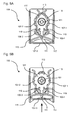
- Fig. 5a shows a cross-sectional view through the connector 100 in the locked state of the spring 107.
- the spring portions 107-1 and 107-2 are connected in cross with the pressure portion 107-3 of the spring 107. Due to the crossed arrangement of the spring sections 107-1 and 107-2, a better lever transmission is achieved when the pressure section 107-3 is pressed. This allows for easier assembly / disassembly of the connector.
- the spring housing 115 includes the two stops 109-1 and 109-2.
- the spring portion 107-1 abuts against the stop 109-1 and the spring portion 107-2 abuts against the stop 109-2.
- the stopper 109-1 serves to spread the spring portion 107-1.
- the stop 109-2 serves to spread the spring portion 107-2.
- the two stops 109-1 and 109-2 are triangular in cross-section, so that the movement of the spring portions 107-1 and 107-2 is not affected.
- the stops 109-1 and 109-2 are each integrally formed with a centering rib 119. As a result, the stops 109-1 and 109-2 can be arranged directly on the edge of the opening 127.
- the joint formation of the stops 109-1 and 109-2 with the centering rib 119 increases both the strength of the centering rib 119 and the stops 109-1 and 109-2.
- the two spring sections 107-1 and 107-2 abut against the spacer 113.
- the spacer 113 is disposed on an opposite side to the stoppers 109-1 and 109-2 within the laterally closed spring housing 115.
- a predetermined position of the spring sections 107-1 and 107-2 can be ensured. If the connecting piece 103 has an inclined edge, the spring sections 107-1 and 107-2 automatically slide into the groove 105 when the plug-in connector is slid on.
- the unlocking is formed by manually pressing the printing section 107-3 in the arrow direction in the arcuate recess 117.
- the pressure section 107-3 is thereby displaced in the direction of the Einsteckstutzens 101.
- the two spring portions 107-1 and 107-2 are pushed outwardly and move out of the groove 105 of the connecting piece 103.
- the connector 100 is released and can be pulled down from the connecting piece 103.
- the stop 109-2 for the spring portion 107-2 is disposed on a left side of the spring housing 115.
- the stop 109-1 for the spring portion 107-1 is disposed on a right side of the spring housing 115.
- Fig. 6 shows a further perspective view of the connector 100.
- the spring 107 moves when placed on the connecting piece 103 automatically aside.
- the cylindrical Einsteckstutzen 101 protrudes perpendicularly from the center of the opening of the spring housing 115 out.
- the peripherally arranged centering ribs 119 are after touchdown on the outside of the connecting piece 103.
- Fig. 7 shows a perspective view of the spring 107.
- the spring portions 107-1 and 107-2 comprise a circular segment-shaped portion having a radius corresponding to the radius of the groove 105 of the connecting piece 103.
- the ends of the spring portions 107-1 and 107-2 are bent outwardly. The bent ends abut when pressing the spring 107 on the side walls of the spring housing 115, so that overstretching of the spring 107 is avoided.
- the right spring portion 107-1 is resiliently connected to the straight connection portion 107-5 with the left side of the straight pressure portion 107-3.
- the left spring portion 107-2 is resiliently connected to the straight connection portion 107-4 with the right side of the straight pressure portion 107-3.
- the connecting portions 107-4 and 107-5 intersect at the center of the spring 107.
- the levers are exerted via the connecting portions 107-4 and 107-5 via the stops 109-1 and 109-2.
Landscapes
- Engineering & Computer Science (AREA)
- General Engineering & Computer Science (AREA)
- Mechanical Engineering (AREA)
- Chemical & Material Sciences (AREA)
- Combustion & Propulsion (AREA)
- Quick-Acting Or Multi-Walled Pipe Joints (AREA)
- Details Of Connecting Devices For Male And Female Coupling (AREA)
Abstract
Description
- Die vorliegende Erfindung betrifft einen Steckverbinder zum Herstellen einer Fluidverbindung.
- Die Druckschrift
DE 10 2012 005 929 A1 beschreibt eine Steckverbindungsanordnung zum lösbaren Verbinden von Fluidleitungen. Zum Verriegeln der Steckverbindungsanordnung befindet sich ein Fixierelement ein einer Einschuböffnung. Das Fixierelement wird aus der radialen Einschuböffnung herausgezogen, um die Steckverbindung zerstörungsfrei zu lösen. - Es ist die der Erfindung zugrundeliegende Aufgabe, einen Steckverbinder für eine Fluidleitung anzugeben, der auf einfachere Weise gelöst werden kann.
- Diese Aufgabe wird durch den Gegenstand mit den Merkmalen nach dem unabhängigen Anspruch gelöst. Vorteilhafte Ausführungsformen der Erfindung sind Gegenstand der Figuren, der Beschreibung und der abhängigen Ansprüche.
- Gemäß einem Aspekt der Erfindung wird die Aufgabe durch einen Steckverbinder zum Herstellen einer Fluidverbindung gelöst, mit einem Einsteckstutzen zum Einsetzen in einen Anschlussstutzen, der eine außen umlaufende Nut umfasst; einer Feder zum Verriegeln des Einsteckstutzens an dem Anschlussstutzen, die einen ersten Federabschnitt zum Eingreifen in eine erste Seite der Nut des Anschlussstutzens, einen zweiten Federabschnitt zum Eingreifen in eine zweite Seite der Nut des Anschlussstutzens und einen Druckabschnitt zum Drücken der Feder in Richtung des Einsteckstutzens umfasst; und einem Anschlag zum Spreizen des ersten und des zweiten Federabschnittes beim Drücken des Druckabschnittes. Dadurch wird beispielsweise der technische Vorteil erreicht, dass eine leichte Montage und Demontage des Steckverbinders erreicht wird.
- In einer vorteilhaften Ausführungsform des Steckverbinders sind der erste Federabschnitt und der zweite Federabschnitt über kreuz federnd mit dem Druckabschnitt verbunden.
Dadurch wird beispielsweise der technische Vorteil erreicht, dass eine große Hebelübersetzung und damit eine Verringerung der notwendigen Kraft erreicht wird. - In einer weiteren vorteilhaften Ausführungsform des Steckverbinders ist die Feder aus gebogenem Runddraht gebildet. Dadurch wird beispielsweise der technische Vorteil erreicht, dass die Feder auf einfache Weise herstellbar ist.
- In einer weiteren vorteilhaften Ausführungsform des Steckverbinders umfasst der Steckverbinder einen Sicherungsvorsprung zum Fixieren der Feder gegen ein Herausziehen. Dadurch wird beispielsweise der technische Vorteil erreicht, dass ein ungewolltes Herausrutschen der Feder verhindert wird.
- In einer weiteren vorteilhaften Ausführungsform des Steckverbinders ist der Sicherungsvorsprung keilförmig ausgebildet, so dass die Feder beim Einsetzen in den Steckverbinder über den Sicherungsvorsprung gleiten kann. Dadurch wird beispielsweise der technische Vorteil erreicht, dass die Montage der Feder vereinfacht wird.
- In einer weiteren vorteilhaften Ausführungsform des Steckverbinders umfasst der Steckverbinder einen Abstandshalter zum gegenseiteigen Beabstanden des ersten Federabschnitts und des zweiten Federabschnitts. Dadurch wird beispielsweise der technische Vorteil erreicht, dass sich die Federabschnitte in einer definierten Ruhelage befinden. Dadurch können sich die Federabschnitte beim Aufsetzen des Steckverbinders auf den Anschlussstutzen automatisch spreizen, bis diese in der umlaufenden Nut einrasten.
- In einer weiteren vorteilhaften Ausführungsform des Steckverbinders ist der Abstandshalter auf einer Seite des Steckverbinders angeordnet, die dem Druckabschnitt gegenüberliegt. Dadurch wird beispielsweise der technische Vorteil erreicht, dass sich die Federabschnitte exakt positionieren lassen.
- In einer weiteren vorteilhaften Ausführungsform des Steckverbinders umfasst der Steckverbinder einen ersten Anschlag zum Spreizen des ersten Federabschnitts und einen zweiten Anschlag zum Spreizen des zweiten Federabschnitts. Dadurch wird beispielsweise der technische Vorteil erreicht, dass für jeden Federabschnitt ein separater Anschlag gebildet wird, über den jeweils eine hohe Hebelübersetzung erreicht wird.
- In einer weiteren vorteilhaften Ausführungsform des Steckverbinders wird der Druckabschnitt durch einen geraden Abschnitt der Feder gebildet. Dadurch wird beispielsweise der technische Vorteil erreicht, dass die Feder manuell mit einer hohen Kraft gedrückt werden kann.
- In einer weiteren vorteilhaften Ausführungsform des Steckverbinders umfasst der Steckverbinder ein Federgehäuse zum Aufnehmen der Feder. Dadurch wird beispielsweise der technische Vorteil erreicht, dass ein versehentliches Beschädigen der Feder vor oder während der Montage verhindert wird.
- In einer weiteren vorteilhaften Ausführungsform des Steckverbinders umfasst das Federgehäuse eine bogenförmige Ausnehmung im Bereich des Druckabschnittes. Dadurch wird beispielsweise der technische Vorteil erreicht, dass die Feder vollständig bis auf den Druckabschnitt umgeben ist.
- In einer weiteren vorteilhaften Ausführungsform des Steckverbinders ist das Federgehäuse seitlich geschlossen. Dadurch wird beispielsweise der technische Vorteil erreicht, dass ein seitliches Eindringen von Schmutz verhindert wird.
- In einer weiteren vorteilhaften Ausführungsform des Steckverbinders ist der Anschlag derart angeordnet, dass beim Drücken auf den Druckabschnitt eine Hebelübersetzung auf den ersten Federabschnitt und den zweiten Federabschnitt ausgeübt wird. Dadurch wird beispielsweise der technische Vorteil erreicht, dass ein leichtgängiges Entriegeln des Steckverbinders ermöglicht wird.
- In einer weiteren vorteilhaften Ausführungsform des Steckverbinders umfasst der Steckverbinder Stutzrippen zum Abstützen des Steckverbinders an dem Anschlussstutzen. Dadurch wird beispielsweise der technische Vorteil erreicht, dass das Aufstecken des Steckverbinders durch eine Selbstzentrierung erleichtert wird.
- In einer weiteren vorteilhaften Ausführungsform des Steckverbinders umfasst der Anschlag eine Zentrierrippe zum Abstützen des Steckverbinders an dem Anschlussstutzen. Dadurch wird beispielsweise der technische Vorteil erreicht, dass die Zentrierrippen vollumfänglich um die Öffnung zum Einsetzen des Anschlussstutzens herum angeordnet werden können. Zudem wird die Stabilität des Anschlags durch die Zentrierrippe verbessert. Der Anschlag kann nahe der Öffnung zum Einsetzen des Anschlussstutzens angeordnet sein.
- Ausführungsbeispiele der Erfindung sind in den Zeichnungen dargestellt und werden im Folgenden näher beschrieben.
- Es zeigen:
- Fig. 1
- eine perspektivische Ansicht eines Steckverbinders;
- Fig. 2
- eine weitere perspektivische Ansicht des Steckverbinders;
- Fig. 3
- eine weitere perspektivische Ansicht des Steckverbinders mit nicht montierter Feder;
- Fig. 4
- eine Untersicht auf den Steckverbinder;
- Fig. 5a
- eine Querschnittsansicht durch den Steckverbinder in verriegeltem Zustand;
- Fig. 5B
- eine Querschnittsansicht durch den Steckverbinder in entriegeltem Zustand;
- Fig. 6
- eine weitere perspektivische Ansicht des Steckverbinders; und
- Fig. 7
- eine perspektivische Ansicht auf die Feder.
-
Fig. 1 zeigt eine perspektivische Ansicht eines Steckverbinders 100. Der Steckverbinder 100 dient zum Herstellen einer Fluidverbindung, wie beispielsweise für eine Kraftstoffleitung in einem Motor eines Kraftfahrzeugs. - Der Steckverbinder 100 umfasst einen Einsteckstutzen 101 zum Einsetzen in einen Anschlussstutzen 103. Der Anschlussstutzen 103 umfasst eine außen umlaufende Nut 105. Eine Feder 107 dient zum Verriegeln des Einsteckstutzens 101 an dem Anschlussstutzen 103, indem diese in die Nut 105 des Anschlussstutzens 103 eingreift und den Steckverbinder 100 verriegelt. Wird die Feder 107 durch Drücken eines Druckabschnittes 107-3 betätigt, wird die Verriegelung des Steckverbinders 100 gelöst. Der Steckverbinder 100 kann so von dem Anschlussstutzen heruntergezogen werden.
- Die Feder 107 ist im Inneren eines Federgehäuses 115 angeordnet, das eine bogenförmige Ausnehmung 117 im Bereich des Druckabschnittes 107-3 der Feder 107 umfasst. Die bogenförmige Ausnehmung 117 erlaubt ein manuelles Drücken des Druckabschnittes 107-3 in Richtung des Einsteckstutzens 101.
- Das Federgehäuse 115 bildet eine Einhausung, durch die die Feder 107 komplett geschützt ist. Dadurch kann ein Hängenbleiben bei der Montage und ein versehentliches Beschädigen der Feder 107 vor oder während der Montage verhindert werden. Eine versehentliche Entriegelung der Feder 107 ist nicht möglich. Im Inneren des Federgehäuses 115 ist ein Sicherungsvorsprung 111 angeordnet, an dem die Feder 107 anliegt. Dadurch wird die Feder 107 gegen ein Herausziehen aus dem Federgehäuse 115 gesichert.
- Der Einsteckstutzen 101 ist T-förmig mit zwei seitlich herausragenden Seitenstutzen 123-1 und 123-2 verbunden, die zum Aufstecken von Schlauchleitungen dienen. Die beiden Seitenstutzen 123-1 und 123-2 sind in einem stumpfen Winkel zueinander angeordnet. Oberhalb der beiden Seitenstutzen 123-1 und 123-2 ist eine flügelartige Schutzplatte 125 angeordnet, die die beiden abgewinkelten Seitenstutzen 123-1 und 123-2 überdeckt. Die Schutzplatte 125 ist über senkrechte Stützflächen mit den beiden Seitenstutzen 123-1 und 123-2 verbunden.
-
Fig. 2 zeigt eine weitere perspektivische Ansicht des Steckverbinders 100. Der Einsteckstutzen 101 umfasst einen Dichtungsring 121 zum Abdichten des Zwischenraums zwischen dem Einsteckstutzen 101 und dem Anschlussstutzen 103. In dem Federgehäuse 115 ist ein Abstandshalter 113 auf einer Seite angeordnet ist, die dem Druckabschnitt 107-3 gegenüberliegt. - Die flügelartige Schutzplatte 125 über den Seitenstutzen 123-1 und 123-2 ergibt eine größere Druckfläche für eine Montage und schützt die Seitenstutzen 123-1 und 123-2 vor einer Beschädigung. Die Seitenstutzen 123-1 und 123-2 sind ebenfalls über senkrechte Stützflächen mit dem Federgehäuse 115 verbunden. Zusätzlich sind die Schutzplatte 125 und die Seitenstutzen 123-1 und 123-2 über trapezartige Stutzflächen mit dem Federgehäuse 115 verbunden. Die trapezartigen Stutzflächen sind senkrecht zu den Stutzflächen angeordnet, die die Schutzplatte 125 an den Seitenstutzen 123-1 und 123-2 abstützen. Durch diesen gerüstartigen Aufbau wird eine hohe Stabilität des Steckverbinders 100 erreicht.
-
Fig. 3 zeigt eine weitere perspektivische Ansicht des Steckverbinders 100 mit herausgezogener Feder 107. Die Feder 107 umfasst zwei gegenüber liegende Federabschnitte 107-1 und 107-2 zum Eingreifen in die Nut 105 des Anschlussstutzens 103. Die beiden Federabschnitte 107-1 und 107-2 sind über kreuz federnd mit dem Druckabschnitt 107-3 der Feder 107 verbunden. - Bei der Herstellung des Steckverbinders wird die Feder 107 von Außen in das Federgehäuse 115 geschoben. Dabei gleitet die Feder 107 über den keilförmig ausgebildeten Sicherungsvorsprung 111 und wird anschließend durch den Sicherungsvorsprung 111 innerhalb des Federgehäuses 115 fixiert.
-
Fig. 4 zeigt eine Untersicht auf den Steckverbinder 100. Das Federgehäuse 115 umfasst eine Öffnung 127, in der der Anschlussstutzen 103 eingesetzt wird. Nach dem Einsetzen des Anschlussstutzens 103 befindet sich die Nut 105 im Inneren des Federgehäuses 115. Die beiden Federabschnitte 107-1 und 107-2 greifen beiderseits in die Nut 105 ein. Im Inneren des Federgehäuses 115 sind Zentrierrippen 119 angeordnet, die ein Aufstecken durch Selbstzentrierung des Steckverbinders 100 erleichtern und das radiale Spiels reduzieren. Die Zentrierrippen 119 sind gleichmäßig um die Öffnung 127 herum angeordnet und ragen vom Rand der Öffnung 127 radial nach Innen. Im Bereich der Federabschnitte 107-1 und 107-2 sind die Zentrierrippen 119 unterbrochen, so dass sich die Federabschnitte 107-1 und 107-2 seitlich nach außen bewegen können. -
Fig. 5a zeigt eine Querschnittsansicht durch den Steckverbinder 100 in verriegeltem Zustand der Feder 107. Die Federabschnitte 107-1 und 107-2 sind über Kreuz mit dem Druckabschnitt 107-3 der Feder 107 verbunden. Durch die gekreuzte Anordnung der Federabschnitte 107-1 und 107-2 wird beim Drücken des Druckabschnittes 107-3 eine bessere Hebelübersetzung erreicht. Dies ermöglicht eine leichtere Montage/Demontage des Steckverbinders. - Das Federgehäuse 115 umfasst die beiden Anschläge 109-1 und 109-2. Der Federabschnitt 107-1 liegt an dem Anschlag 109-1 an und der Federabschnitt 107-2 liegt an dem Anschlag 109-2 an. Der Anschlag 109-1 dient zum Spreizen des Federabschnitts 107-1. Der Anschlag 109-2 dient zum Spreizen des Federabschnitts 107-2. Die beiden Anschläge 109-1 und 109-2 sind im Querschnitt dreiecksförmig, so dass die Bewegung der Federabschnitte 107-1 und 107-2 nicht beeinträchtigt wird. Die Anschläge 109-1 und 109-2 sind jeweils integral mit einer Zentrierrippe 119 ausgebildet. Dadurch können die Anschläge 109-1 und 109-2 unmittelbar am Rand der Öffnung 127 angeordnet sein. Durch die gemeinsame Ausbildung der Anschläge 109-1 und 109-2 mit der Zentrierrippe 119 steigt sowohl die Festigkeit der Zentrierrippe 119 als auch der Anschläge 109-1 und 109-2.
- In der Ruhelage liegen die beiden Federabschnitte 107-1 und 107-2 an dem Abstandshalter 113 an. Der Abstandshalter 113 ist an einer gegenüberliegenden Seite zu den Anschlägen 109-1 und 109-2 innerhalb des seitlich geschlossenen Federgehäuses 115 angeordnet. Dadurch kann in der Ruhelage eine vorgegebene Position der Federabschnitte 107-1 und 107-2 gewährleistet werden. Weist der Anschlussstutzen 103 einen geneigten Rand auf, gleiten die Federabschnitte 107-1 und 107-2 beim Aufschieben des Steckverbinders selbsttätig in die Nut 105.
-
Fig. 5B zeigt eine Querschnittsansicht durch den Steckverbinder in entriegeltem Zustand der Feder 107. Die Entriegelung entsteht durch manuelles Drücken des Druckabschnittes 107-3 in Pfeilrichtung in die bogenförmige Ausnehmung 117. Der Druckabschnitt 107-3 wird dabei in Richtung des Einsteckstutzens 101 verschoben. Dabei werden die beiden Federabschnitte 107-1 und 107-2 nach außen gedrückt und bewegen sich aus der Nut 105 des Anschlussstutzens 103. Der Steckverbinder 100 wird freigegeben und kann von dem Anschlussstutzen 103 heruntergezogen werden. - Der Anschlag 109-2 für den Federabschnitt 107-2 ist auf einer linken Seite des Federgehäuses 115 angeordnet. Dadurch dass der rechte Federabschnitt 107-1 mit der linken Seite des Druckabschnitts 107-3 verbunden ist und der linke Federabschnitt 107-2 mit der rechten Seite des Druckabschnitts 107-3 verbunden ist, kann über die beiden Anschläge 109-1 und 109-2 auf geringem Raum eine hohe Hebelübersetzung zum Spreizen der Feder 107 erzeugt werden. Der Anschlag 109-1 für den Federabschnitt 107-1 ist auf einer rechten Seite des Federgehäuses 115 angeordnet.
- Dies ermöglicht eine einfache Demontage und leichtgängige Entriegelung des Steckverbinders 100 durch einfaches Drücken der Feder 107. Nach dem Loslassen des Druckabschnitts 107-3 kehrt die Feder 107 selbstständig in Ausgangslage zurück, in der die beiden Federabschnitte 107-1 und 107-2 an dem Abstandshalter 113 anliegen.
-
Fig. 6 zeigt eine weitere perspektivische Ansicht des Steckverbinders 100. Die Feder 107 bewegt sich beim Aufsetzen auf den Anschlussstutzen 103 selbstständig zur Seite. Der zylindrische Einsteckstutzen 101 ragt senkrecht aus der Mitte der Öffnung des Federgehäuses 115 heraus. Die umfangseitig angeordneten Zentrierrippen 119 liegen nach dem Aufsetzen an der Außenseite des Anschlussstutzens 103 an. -
Fig. 7 zeigt eine perspektivische Ansicht auf die Feder 107. Die Federabschnitte 107-1 und 107-2 umfassen einen kreissegmentförmigen Abschnitt mit einem Radius, der dem Radius der Nut 105 des Anschlussstutzens 103 entspricht. Die Enden der Federabschnitte 107-1 und 107-2 sind nach außen hin abgebogen. Die abgebogenen Enden stoßen beim Drücken der Feder 107 an den Seitenwänden des Federgehäuses 115 an, so dass ein Überdehnen der Feder 107 vermieden wird. - Der rechte Federabschnitt 107-1 ist mit dem geraden Verbindungsabschnitt 107-5 mit der linken Seite des geraden Druckabschnittes 107-3 federnd verbunden. Der linke Federabschnitt 107-2 ist mit dem geraden Verbindungsabschnitt 107-4 mit der rechten Seite des geraden Druckabschnittes 107-3 federnd verbunden. Die Verbindungsabschnitte 107-4 und 107-5 kreuzen sich in der Mitte der Feder 107. Über die Verbindungsabschnitte 107-4 und 107-5 wird über die Anschläge 109-1 und 109-2 die Hebelübersetzung ausgeübt.
- Alle in Verbindung mit einzelnen Ausführungsformen der Erfindung erläuterten und gezeigten Merkmale können in unterschiedlicher Kombination in dem erfindungsgemäßen Gegenstand vorgesehen sein, um gleichzeitig deren vorteilhafte Wirkungen zu realisieren.
- Der Schutzbereich der vorliegenden Erfindung ist durch die Ansprüche gegeben und wird durch die in der Beschreibung erläuterten oder den Figuren gezeigten Merkmale nicht beschränkt.
-
- 100
- Steckverbinder
- 101
- Einsteckstutzen
- 103
- Anschlussstutzen
- 105
- Nut
- 107
- Feder
- 107-1
- Federabschnitt
- 107-2
- Federabschnitt
- 107-3
- Druckabschnitt
- 107-4
- Verbindungsabschnitt
- 107-5
- Verbindungsabschnitt
- 109-1
- Anschlag
- 109-2
- Anschlag
- 111
- Sicherungsvorsprung
- 113
- Abstandshalter
- 115
- Federgehäuse
- 117
- Ausnehmung
- 119
- Zentrierrippe
- 121
- Dichtungsring
- 123-1
- Seitenstutzen
- 123-2
- Seitenstutzen
- 125
- Schutzplatte
- 127
- Öffnung
Claims (15)
- Steckverbinder (100) zum Herstellen einer Fluidverbindung, mit:einem Einsteckstutzen (101) zum Einsetzen in einen Anschlussstutzen (103), der eine außen umlaufende Nut (105) umfasst;einer Feder (107) zum Verriegeln des Einsteckstutzens (101) an dem Anschlussstutzen, die einen ersten Federabschnitt (107-1) zum Eingreifen in eine erste Seite der Nut des Anschlussstutzens, einen zweiten Federabschnitt (107-2) zum Eingreifen in eine zweite Seite der Nut des Anschlussstutzens und einen Druckabschnitt (107-3) zum Drücken der Feder (107) in Richtung des Einsteckstutzens (101) umfasst; undeinem Anschlag (109-1, 109-2) zum Spreizen des ersten und des zweiten Federabschnittes (107-1, 107-2) beim Drücken des Druckabschnittes (107-3).
- Steckverbinder (100) nach Anspruch 1, wobei der erste Federabschnitt (107-1) und der zweite Federabschnitt (107-2) über kreuz federnd mit dem Druckabschnitt (107-3) verbunden sind.
- Steckverbinder (100) nach einem der vorangehenden Ansprüche, wobei die Feder (107) aus gebogenem Runddraht gebildet ist.
- Steckverbinder (100) nach einem der vorangehenden Ansprüche, wobei der Steckverbinder (100) einen Sicherungsvorsprung (111) zum Fixieren der Feder (107) gegen ein Herausziehen umfasst.
- Steckverbinder (100) nach Anspruch 4, wobei der Sicherungsvorsprung (111) keilförmig ausgebildet ist, so dass die Feder (107) beim Einsetzen in den Steckverbinder (100) über den Sicherungsvorsprung (111) gleiten kann.
- Steckverbinder (100) nach einem der vorangehenden Ansprüche, wobei der Steckverbinder (100) einen Abstandshalter (113) zum gegenseiteigen Beabstanden des ersten Federabschnitts (107-1) und des zweiten Federabschnitts (107-2) umfasst.
- Steckverbinder (100) nach Anspruch 6, wobei der Abstandshalter (113) auf einer Seite des Steckverbinders (100) angeordnet ist, die dem Druckabschnitt (107-3) gegenüberliegt.
- Steckverbinder (100) nach einem der vorangehenden Ansprüche, wobei der Steckverbinder (100) einen ersten Anschlag (109-1) zum Spreizen des ersten Federabschnitts (107-1) und einen zweiten Anschlag (109-2) zum Spreizen des zweiten Federabschnitts (107-2) umfasst.
- Steckverbinder (100) nach einem der vorangehenden Ansprüche, wobei der Druckabschnitt (107-3) durch einen geraden Abschnitt der Feder (107) gebildet wird.
- Steckverbinder (100) nach einem der vorangehenden Ansprüche, wobei der Steckverbinder (100) ein Federgehäuse (115) zum Aufnehmen der Feder (107) umfasst.
- Steckverbinder (100) nach Anspruch 10, wobei das Federgehäuse (115) eine bogenförmige Ausnehmung (117) im Bereich des Druckabschnittes (107-3) umfasst.
- Steckverbinder (100) nach Anspruch 10 oder 11, wobei das Federgehäuse (115) seitlich geschlossen ist.
- Steckverbinder (100) nach einem der vorangehenden Ansprüche, wobei der Anschlag (109-1, 109-2) derart angeordnet ist, dass beim Drücken auf den Druckabschnitt (107-3) eine Hebelübersetzung auf den ersten Federabschnitt (107-1) und den zweiten Federabschnitt (107-2) ausgeübt wird.
- Steckverbinder (100) nach einem der vorangehenden Ansprüche, wobei der Steckverbinder (100) Stutzrippen (119) zum Abstützen des Steckverbinders (100) an dem Anschlussstutzen umfasst.
- Steckverbinder (100) nach Anspruch 4, wobei der Anschlag (109-1, 109-2) eine Zentrierrippe (119) zum Abstützen des Steckverbinders (100) an dem Anschlussstutzen umfasst.
Applications Claiming Priority (1)
| Application Number | Priority Date | Filing Date | Title |
|---|---|---|---|
| DE102014103405.8A DE102014103405A1 (de) | 2014-03-13 | 2014-03-13 | Steckverbinder |
Publications (2)
| Publication Number | Publication Date |
|---|---|
| EP2927472A1 true EP2927472A1 (de) | 2015-10-07 |
| EP2927472B1 EP2927472B1 (de) | 2017-10-25 |
Family
ID=52669483
Family Applications (1)
| Application Number | Title | Priority Date | Filing Date |
|---|---|---|---|
| EP15157909.1A Active EP2927472B1 (de) | 2014-03-13 | 2015-03-06 | Steckverbinder |
Country Status (3)
| Country | Link |
|---|---|
| EP (1) | EP2927472B1 (de) |
| DE (1) | DE102014103405A1 (de) |
| ES (1) | ES2654061T3 (de) |
Citations (3)
| Publication number | Priority date | Publication date | Assignee | Title |
|---|---|---|---|---|
| US20030052484A1 (en) * | 2001-02-05 | 2003-03-20 | Stephane Rautureau | Supply connection device for a fluid pressure system |
| DE102012005929A1 (de) | 2012-03-26 | 2013-09-26 | Veritas Ag | Steckverbindungsanordnung |
| EP2644957A1 (de) * | 2012-03-26 | 2013-10-02 | Veritas Ag | Steckverbindungsanordnung |
-
2014
- 2014-03-13 DE DE102014103405.8A patent/DE102014103405A1/de not_active Withdrawn
-
2015
- 2015-03-06 ES ES15157909.1T patent/ES2654061T3/es active Active
- 2015-03-06 EP EP15157909.1A patent/EP2927472B1/de active Active
Patent Citations (3)
| Publication number | Priority date | Publication date | Assignee | Title |
|---|---|---|---|---|
| US20030052484A1 (en) * | 2001-02-05 | 2003-03-20 | Stephane Rautureau | Supply connection device for a fluid pressure system |
| DE102012005929A1 (de) | 2012-03-26 | 2013-09-26 | Veritas Ag | Steckverbindungsanordnung |
| EP2644957A1 (de) * | 2012-03-26 | 2013-10-02 | Veritas Ag | Steckverbindungsanordnung |
Also Published As
| Publication number | Publication date |
|---|---|
| ES2654061T8 (es) | 2018-05-10 |
| ES2654061T3 (es) | 2018-02-12 |
| EP2927472B1 (de) | 2017-10-25 |
| DE102014103405A1 (de) | 2015-09-17 |
Similar Documents
| Publication | Publication Date | Title |
|---|---|---|
| EP2880349B1 (de) | Schnellverbindungsanordnung zur lösbaren verbindung einer medienleitung mit einem stutzen | |
| DE112012003590B4 (de) | Verbinder | |
| EP2076705B1 (de) | Kupplungsteil für eine fluidleitungskupplung | |
| EP3149384B1 (de) | Steckverbinder für fluidleitungen mit innenliegender adapterhülse | |
| DE10115399C1 (de) | Lösbare Steckverbindung mit zusätzlichem Verriegelungselement | |
| EP1158236B1 (de) | Kupplungsvorrichtung mit einem U-förmigen Verriegelungselement | |
| DE102011118099A1 (de) | Vorrichtung zum Verbinden zweier Leitungsabschnitte | |
| EP3491281B1 (de) | Anschlussverbinder und anordnung eines halteelements und einer verriegelungseinrichtung dafür | |
| EP4066325B1 (de) | Sekundärverriegelungsvorrichtung | |
| DE102011085398A1 (de) | Verbindungseinheit | |
| DE102017011081A1 (de) | Filtersystem und Filterelement | |
| WO2016038226A1 (de) | Verriegelungselement für einen konnektor | |
| DE102015105832B4 (de) | Elektrische Steckverbindung und Verfahren zum Lösen einer elektrischen Steckverbindung | |
| EP3884197B1 (de) | Kopplung | |
| DE102021129676A1 (de) | Steckverbindung mit Verriegelungs- und Entriegelungsvorrichtung | |
| DE102016104303A1 (de) | Sekundärverriegelungsmittel zum Verhindern des Lösens einer Primärverriegelung eines elektrischen Steckverbinders sowie Verriegelungsanordnung aus zwei Sekundärverriegelungsmitteln | |
| EP2405147B1 (de) | Befestigungsbaugruppe | |
| EP3775658A1 (de) | Anschlussvorrichtung für medienleitungen | |
| EP2369215B1 (de) | Steckverbindung | |
| DE102018104017A1 (de) | Steckverbinder mit Polarisationselement sowie ein System und ein Verfahren zum Montieren, zum Stecken und zum Trennen dieses Steckverbinders | |
| EP2927472B1 (de) | Steckverbinder | |
| EP3244113A1 (de) | Verriegelungsbügel für einen stutzen eines schnellkupplungssystems | |
| EP1186823A2 (de) | Schnellkupplung zum Verbinden von Leitungsenden | |
| DE102022104970A1 (de) | Steckverbinder mit Montagesicherung | |
| DE4022769C2 (de) | Rohrleitungsmehrfachkupplung |
Legal Events
| Date | Code | Title | Description |
|---|---|---|---|
| PUAI | Public reference made under article 153(3) epc to a published international application that has entered the european phase |
Free format text: ORIGINAL CODE: 0009012 |
|
| AK | Designated contracting states |
Kind code of ref document: A1 Designated state(s): AL AT BE BG CH CY CZ DE DK EE ES FI FR GB GR HR HU IE IS IT LI LT LU LV MC MK MT NL NO PL PT RO RS SE SI SK SM TR |
|
| AX | Request for extension of the european patent |
Extension state: BA ME |
|
| 17P | Request for examination filed |
Effective date: 20160315 |
|
| RBV | Designated contracting states (corrected) |
Designated state(s): AL AT BE BG CH CY CZ DE DK EE ES FI FR GB GR HR HU IE IS IT LI LT LU LV MC MK MT NL NO PL PT RO RS SE SI SK SM TR |
|
| GRAP | Despatch of communication of intention to grant a patent |
Free format text: ORIGINAL CODE: EPIDOSNIGR1 |
|
| STAA | Information on the status of an ep patent application or granted ep patent |
Free format text: STATUS: GRANT OF PATENT IS INTENDED |
|
| RIC1 | Information provided on ipc code assigned before grant |
Ipc: F02M 55/00 20060101AFI20170516BHEP Ipc: F16L 37/088 20060101ALI20170516BHEP |
|
| INTG | Intention to grant announced |
Effective date: 20170614 |
|
| GRAS | Grant fee paid |
Free format text: ORIGINAL CODE: EPIDOSNIGR3 |
|
| GRAA | (expected) grant |
Free format text: ORIGINAL CODE: 0009210 |
|
| STAA | Information on the status of an ep patent application or granted ep patent |
Free format text: STATUS: THE PATENT HAS BEEN GRANTED |
|
| AK | Designated contracting states |
Kind code of ref document: B1 Designated state(s): AL AT BE BG CH CY CZ DE DK EE ES FI FR GB GR HR HU IE IS IT LI LT LU LV MC MK MT NL NO PL PT RO RS SE SI SK SM TR |
|
| REG | Reference to a national code |
Ref country code: GB Ref legal event code: FG4D Free format text: NOT ENGLISH |
|
| REG | Reference to a national code |
Ref country code: CH Ref legal event code: EP |
|
| REG | Reference to a national code |
Ref country code: AT Ref legal event code: REF Ref document number: 940200 Country of ref document: AT Kind code of ref document: T Effective date: 20171115 |
|
| REG | Reference to a national code |
Ref country code: IE Ref legal event code: FG4D Free format text: LANGUAGE OF EP DOCUMENT: GERMAN |
|
| REG | Reference to a national code |
Ref country code: DE Ref legal event code: R096 Ref document number: 502015002169 Country of ref document: DE |
|
| REG | Reference to a national code |
Ref country code: ES Ref legal event code: FG2A Ref document number: 2654061 Country of ref document: ES Kind code of ref document: T3 Effective date: 20180212 |
|
| REG | Reference to a national code |
Ref country code: NL Ref legal event code: MP Effective date: 20171025 |
|
| REG | Reference to a national code |
Ref country code: LT Ref legal event code: MG4D |
|
| REG | Reference to a national code |
Ref country code: FR Ref legal event code: PLFP Year of fee payment: 4 |
|
| PG25 | Lapsed in a contracting state [announced via postgrant information from national office to epo] |
Ref country code: NL Free format text: LAPSE BECAUSE OF FAILURE TO SUBMIT A TRANSLATION OF THE DESCRIPTION OR TO PAY THE FEE WITHIN THE PRESCRIBED TIME-LIMIT Effective date: 20171025 |
|
| PG25 | Lapsed in a contracting state [announced via postgrant information from national office to epo] |
Ref country code: NO Free format text: LAPSE BECAUSE OF FAILURE TO SUBMIT A TRANSLATION OF THE DESCRIPTION OR TO PAY THE FEE WITHIN THE PRESCRIBED TIME-LIMIT Effective date: 20180125 Ref country code: SE Free format text: LAPSE BECAUSE OF FAILURE TO SUBMIT A TRANSLATION OF THE DESCRIPTION OR TO PAY THE FEE WITHIN THE PRESCRIBED TIME-LIMIT Effective date: 20171025 Ref country code: FI Free format text: LAPSE BECAUSE OF FAILURE TO SUBMIT A TRANSLATION OF THE DESCRIPTION OR TO PAY THE FEE WITHIN THE PRESCRIBED TIME-LIMIT Effective date: 20171025 Ref country code: LT Free format text: LAPSE BECAUSE OF FAILURE TO SUBMIT A TRANSLATION OF THE DESCRIPTION OR TO PAY THE FEE WITHIN THE PRESCRIBED TIME-LIMIT Effective date: 20171025 |
|
| RIN2 | Information on inventor provided after grant (corrected) |
Inventor name: SCHEICHER, STEFFEN Inventor name: COEL, ISA Inventor name: STEHLE, ALEXANDER |
|
| PG25 | Lapsed in a contracting state [announced via postgrant information from national office to epo] |
Ref country code: BG Free format text: LAPSE BECAUSE OF FAILURE TO SUBMIT A TRANSLATION OF THE DESCRIPTION OR TO PAY THE FEE WITHIN THE PRESCRIBED TIME-LIMIT Effective date: 20180125 Ref country code: LV Free format text: LAPSE BECAUSE OF FAILURE TO SUBMIT A TRANSLATION OF THE DESCRIPTION OR TO PAY THE FEE WITHIN THE PRESCRIBED TIME-LIMIT Effective date: 20171025 Ref country code: HR Free format text: LAPSE BECAUSE OF FAILURE TO SUBMIT A TRANSLATION OF THE DESCRIPTION OR TO PAY THE FEE WITHIN THE PRESCRIBED TIME-LIMIT Effective date: 20171025 Ref country code: GR Free format text: LAPSE BECAUSE OF FAILURE TO SUBMIT A TRANSLATION OF THE DESCRIPTION OR TO PAY THE FEE WITHIN THE PRESCRIBED TIME-LIMIT Effective date: 20180126 Ref country code: IS Free format text: LAPSE BECAUSE OF FAILURE TO SUBMIT A TRANSLATION OF THE DESCRIPTION OR TO PAY THE FEE WITHIN THE PRESCRIBED TIME-LIMIT Effective date: 20180225 Ref country code: RS Free format text: LAPSE BECAUSE OF FAILURE TO SUBMIT A TRANSLATION OF THE DESCRIPTION OR TO PAY THE FEE WITHIN THE PRESCRIBED TIME-LIMIT Effective date: 20171025 |
|
| REG | Reference to a national code |
Ref country code: DE Ref legal event code: R097 Ref document number: 502015002169 Country of ref document: DE |
|
| PG25 | Lapsed in a contracting state [announced via postgrant information from national office to epo] |
Ref country code: SK Free format text: LAPSE BECAUSE OF FAILURE TO SUBMIT A TRANSLATION OF THE DESCRIPTION OR TO PAY THE FEE WITHIN THE PRESCRIBED TIME-LIMIT Effective date: 20171025 Ref country code: CZ Free format text: LAPSE BECAUSE OF FAILURE TO SUBMIT A TRANSLATION OF THE DESCRIPTION OR TO PAY THE FEE WITHIN THE PRESCRIBED TIME-LIMIT Effective date: 20171025 Ref country code: CY Free format text: LAPSE BECAUSE OF FAILURE TO SUBMIT A TRANSLATION OF THE DESCRIPTION OR TO PAY THE FEE WITHIN THE PRESCRIBED TIME-LIMIT Effective date: 20171025 Ref country code: DK Free format text: LAPSE BECAUSE OF FAILURE TO SUBMIT A TRANSLATION OF THE DESCRIPTION OR TO PAY THE FEE WITHIN THE PRESCRIBED TIME-LIMIT Effective date: 20171025 Ref country code: EE Free format text: LAPSE BECAUSE OF FAILURE TO SUBMIT A TRANSLATION OF THE DESCRIPTION OR TO PAY THE FEE WITHIN THE PRESCRIBED TIME-LIMIT Effective date: 20171025 |
|
| PG25 | Lapsed in a contracting state [announced via postgrant information from national office to epo] |
Ref country code: RO Free format text: LAPSE BECAUSE OF FAILURE TO SUBMIT A TRANSLATION OF THE DESCRIPTION OR TO PAY THE FEE WITHIN THE PRESCRIBED TIME-LIMIT Effective date: 20171025 Ref country code: PL Free format text: LAPSE BECAUSE OF FAILURE TO SUBMIT A TRANSLATION OF THE DESCRIPTION OR TO PAY THE FEE WITHIN THE PRESCRIBED TIME-LIMIT Effective date: 20171025 Ref country code: SM Free format text: LAPSE BECAUSE OF FAILURE TO SUBMIT A TRANSLATION OF THE DESCRIPTION OR TO PAY THE FEE WITHIN THE PRESCRIBED TIME-LIMIT Effective date: 20171025 |
|
| PLBE | No opposition filed within time limit |
Free format text: ORIGINAL CODE: 0009261 |
|
| STAA | Information on the status of an ep patent application or granted ep patent |
Free format text: STATUS: NO OPPOSITION FILED WITHIN TIME LIMIT |
|
| PG25 | Lapsed in a contracting state [announced via postgrant information from national office to epo] |
Ref country code: MT Free format text: LAPSE BECAUSE OF FAILURE TO SUBMIT A TRANSLATION OF THE DESCRIPTION OR TO PAY THE FEE WITHIN THE PRESCRIBED TIME-LIMIT Effective date: 20171025 |
|
| 26N | No opposition filed |
Effective date: 20180726 |
|
| REG | Reference to a national code |
Ref country code: CH Ref legal event code: PL |
|
| PG25 | Lapsed in a contracting state [announced via postgrant information from national office to epo] |
Ref country code: MC Free format text: LAPSE BECAUSE OF FAILURE TO SUBMIT A TRANSLATION OF THE DESCRIPTION OR TO PAY THE FEE WITHIN THE PRESCRIBED TIME-LIMIT Effective date: 20171025 Ref country code: SI Free format text: LAPSE BECAUSE OF FAILURE TO SUBMIT A TRANSLATION OF THE DESCRIPTION OR TO PAY THE FEE WITHIN THE PRESCRIBED TIME-LIMIT Effective date: 20171025 |
|
| REG | Reference to a national code |
Ref country code: BE Ref legal event code: MM Effective date: 20180331 |
|
| REG | Reference to a national code |
Ref country code: IE Ref legal event code: MM4A |
|
| PG25 | Lapsed in a contracting state [announced via postgrant information from national office to epo] |
Ref country code: LU Free format text: LAPSE BECAUSE OF NON-PAYMENT OF DUE FEES Effective date: 20180306 |
|
| PG25 | Lapsed in a contracting state [announced via postgrant information from national office to epo] |
Ref country code: IE Free format text: LAPSE BECAUSE OF NON-PAYMENT OF DUE FEES Effective date: 20180306 |
|
| PG25 | Lapsed in a contracting state [announced via postgrant information from national office to epo] |
Ref country code: BE Free format text: LAPSE BECAUSE OF NON-PAYMENT OF DUE FEES Effective date: 20180331 Ref country code: LI Free format text: LAPSE BECAUSE OF NON-PAYMENT OF DUE FEES Effective date: 20180331 Ref country code: CH Free format text: LAPSE BECAUSE OF NON-PAYMENT OF DUE FEES Effective date: 20180331 |
|
| PGFP | Annual fee paid to national office [announced via postgrant information from national office to epo] |
Ref country code: ES Payment date: 20190424 Year of fee payment: 5 |
|
| GBPC | Gb: european patent ceased through non-payment of renewal fee |
Effective date: 20190306 |
|
| PG25 | Lapsed in a contracting state [announced via postgrant information from national office to epo] |
Ref country code: GB Free format text: LAPSE BECAUSE OF NON-PAYMENT OF DUE FEES Effective date: 20190306 |
|
| PG25 | Lapsed in a contracting state [announced via postgrant information from national office to epo] |
Ref country code: TR Free format text: LAPSE BECAUSE OF FAILURE TO SUBMIT A TRANSLATION OF THE DESCRIPTION OR TO PAY THE FEE WITHIN THE PRESCRIBED TIME-LIMIT Effective date: 20171025 |
|
| PG25 | Lapsed in a contracting state [announced via postgrant information from national office to epo] |
Ref country code: PT Free format text: LAPSE BECAUSE OF FAILURE TO SUBMIT A TRANSLATION OF THE DESCRIPTION OR TO PAY THE FEE WITHIN THE PRESCRIBED TIME-LIMIT Effective date: 20171025 |
|
| PG25 | Lapsed in a contracting state [announced via postgrant information from national office to epo] |
Ref country code: MK Free format text: LAPSE BECAUSE OF NON-PAYMENT OF DUE FEES Effective date: 20171025 Ref country code: HU Free format text: LAPSE BECAUSE OF FAILURE TO SUBMIT A TRANSLATION OF THE DESCRIPTION OR TO PAY THE FEE WITHIN THE PRESCRIBED TIME-LIMIT; INVALID AB INITIO Effective date: 20150306 |
|
| PG25 | Lapsed in a contracting state [announced via postgrant information from national office to epo] |
Ref country code: AL Free format text: LAPSE BECAUSE OF FAILURE TO SUBMIT A TRANSLATION OF THE DESCRIPTION OR TO PAY THE FEE WITHIN THE PRESCRIBED TIME-LIMIT Effective date: 20171025 |
|
| REG | Reference to a national code |
Ref country code: AT Ref legal event code: MM01 Ref document number: 940200 Country of ref document: AT Kind code of ref document: T Effective date: 20200306 |
|
| REG | Reference to a national code |
Ref country code: ES Ref legal event code: FD2A Effective date: 20210728 |
|
| PG25 | Lapsed in a contracting state [announced via postgrant information from national office to epo] |
Ref country code: AT Free format text: LAPSE BECAUSE OF NON-PAYMENT OF DUE FEES Effective date: 20200306 |
|
| PG25 | Lapsed in a contracting state [announced via postgrant information from national office to epo] |
Ref country code: ES Free format text: LAPSE BECAUSE OF NON-PAYMENT OF DUE FEES Effective date: 20200307 |
|
| REG | Reference to a national code |
Ref country code: DE Ref legal event code: R082 Ref document number: 502015002169 Country of ref document: DE Ref country code: DE Ref legal event code: R082 Ref document number: 502015002169 Country of ref document: DE Representative=s name: PATENTSHIP PATENTANWALTSGESELLSCHAFT MBH, DE |
|
| P01 | Opt-out of the competence of the unified patent court (upc) registered |
Effective date: 20230515 |
|
| PGFP | Annual fee paid to national office [announced via postgrant information from national office to epo] |
Ref country code: DE Payment date: 20250319 Year of fee payment: 11 |
|
| PGFP | Annual fee paid to national office [announced via postgrant information from national office to epo] |
Ref country code: FR Payment date: 20250324 Year of fee payment: 11 |
|
| REG | Reference to a national code |
Ref country code: DE Ref legal event code: R082 Ref document number: 502015002169 Country of ref document: DE Representative=s name: PATENTSHIP PATENTANWALTSGESELLSCHAFT MBH, DE Ref country code: DE Ref legal event code: R081 Ref document number: 502015002169 Country of ref document: DE Owner name: HDT VERITAS HESSEN GMBH, DE Free format text: FORMER OWNER: VERITAS AG, 63571 GELNHAUSEN, DE |
|
| PGFP | Annual fee paid to national office [announced via postgrant information from national office to epo] |
Ref country code: IT Payment date: 20250331 Year of fee payment: 11 |