EP2927308A1 - Biogas system and method for generating biogas from straw - Google Patents
Biogas system and method for generating biogas from straw Download PDFInfo
- Publication number
- EP2927308A1 EP2927308A1 EP15000919.9A EP15000919A EP2927308A1 EP 2927308 A1 EP2927308 A1 EP 2927308A1 EP 15000919 A EP15000919 A EP 15000919A EP 2927308 A1 EP2927308 A1 EP 2927308A1
- Authority
- EP
- European Patent Office
- Prior art keywords
- straw
- biogas
- fermenter
- fermentation
- bunker
- Prior art date
- Legal status (The legal status is an assumption and is not a legal conclusion. Google has not performed a legal analysis and makes no representation as to the accuracy of the status listed.)
- Granted
Links
Images


Classifications
-
- C—CHEMISTRY; METALLURGY
- C12—BIOCHEMISTRY; BEER; SPIRITS; WINE; VINEGAR; MICROBIOLOGY; ENZYMOLOGY; MUTATION OR GENETIC ENGINEERING
- C12M—APPARATUS FOR ENZYMOLOGY OR MICROBIOLOGY; APPARATUS FOR CULTURING MICROORGANISMS FOR PRODUCING BIOMASS, FOR GROWING CELLS OR FOR OBTAINING FERMENTATION OR METABOLIC PRODUCTS, i.e. BIOREACTORS OR FERMENTERS
- C12M21/00—Bioreactors or fermenters specially adapted for specific uses
- C12M21/16—Solid state fermenters, e.g. for koji production
-
- C—CHEMISTRY; METALLURGY
- C12—BIOCHEMISTRY; BEER; SPIRITS; WINE; VINEGAR; MICROBIOLOGY; ENZYMOLOGY; MUTATION OR GENETIC ENGINEERING
- C12M—APPARATUS FOR ENZYMOLOGY OR MICROBIOLOGY; APPARATUS FOR CULTURING MICROORGANISMS FOR PRODUCING BIOMASS, FOR GROWING CELLS OR FOR OBTAINING FERMENTATION OR METABOLIC PRODUCTS, i.e. BIOREACTORS OR FERMENTERS
- C12M21/00—Bioreactors or fermenters specially adapted for specific uses
- C12M21/04—Bioreactors or fermenters specially adapted for specific uses for producing gas, e.g. biogas
-
- C—CHEMISTRY; METALLURGY
- C12—BIOCHEMISTRY; BEER; SPIRITS; WINE; VINEGAR; MICROBIOLOGY; ENZYMOLOGY; MUTATION OR GENETIC ENGINEERING
- C12M—APPARATUS FOR ENZYMOLOGY OR MICROBIOLOGY; APPARATUS FOR CULTURING MICROORGANISMS FOR PRODUCING BIOMASS, FOR GROWING CELLS OR FOR OBTAINING FERMENTATION OR METABOLIC PRODUCTS, i.e. BIOREACTORS OR FERMENTERS
- C12M23/00—Constructional details, e.g. recesses, hinges
- C12M23/44—Multiple separable units; Modules
-
- C—CHEMISTRY; METALLURGY
- C12—BIOCHEMISTRY; BEER; SPIRITS; WINE; VINEGAR; MICROBIOLOGY; ENZYMOLOGY; MUTATION OR GENETIC ENGINEERING
- C12M—APPARATUS FOR ENZYMOLOGY OR MICROBIOLOGY; APPARATUS FOR CULTURING MICROORGANISMS FOR PRODUCING BIOMASS, FOR GROWING CELLS OR FOR OBTAINING FERMENTATION OR METABOLIC PRODUCTS, i.e. BIOREACTORS OR FERMENTERS
- C12M29/00—Means for introduction, extraction or recirculation of materials, e.g. pumps
- C12M29/02—Percolation
-
- Y—GENERAL TAGGING OF NEW TECHNOLOGICAL DEVELOPMENTS; GENERAL TAGGING OF CROSS-SECTIONAL TECHNOLOGIES SPANNING OVER SEVERAL SECTIONS OF THE IPC; TECHNICAL SUBJECTS COVERED BY FORMER USPC CROSS-REFERENCE ART COLLECTIONS [XRACs] AND DIGESTS
- Y02—TECHNOLOGIES OR APPLICATIONS FOR MITIGATION OR ADAPTATION AGAINST CLIMATE CHANGE
- Y02E—REDUCTION OF GREENHOUSE GAS [GHG] EMISSIONS, RELATED TO ENERGY GENERATION, TRANSMISSION OR DISTRIBUTION
- Y02E50/00—Technologies for the production of fuel of non-fossil origin
- Y02E50/30—Fuel from waste, e.g. synthetic alcohol or diesel
Definitions
- the present invention relates to a biogas plant and more particularly to a biomass power plant for biogas production according to the preamble of claim 1 and to a process for producing biogas from straw.
- the present invention is based on the ideas for a biogas plant, in particular for a biomass power plant and for a process for the production of biogas, which solve the problem of obtaining suitable fermentation substrates in sufficient quantities, especially for larger, industrial-scale plants to economic conditions and process.
- a device for the mechanical digestion and possibly chemical and / or thermal digestion of straw is provided in the biogas plant.
- biogas production in particular biogas production after the solidification process, becomes accessible to a new class of renewable resources.
- straw is available in large quantities and is available at low cost.
- the straw can be used as a supplement to the conventional fresh mass, such as silage from green waste, silage from whole cereal crops, etc., thus providing itself to a variety of large and very large biomass power plants, with for example 20 or more fermenters and a respective electric Power of over 5,000 kW to economic conditions safely.
- the means for thermal digestion of straw comprises a device for saturated steam treatment.
- the device for saturated steam treatment preferably comprises a pressure vessel and means adapted to generate a water vapor in the pressure vessel, with a pressure which is between 20 and 30 bar and a temperature which is between 180 ° C and 250 ° C. Saturated steam treatment takes place at the pressures and temperatures described and typically lasts for 5 to 15 minutes. The function of the saturated steam treatment will be described using the example of wheat straw.
- Wheat straw consists of about 40% cellulose, 23% arabinoxylan (hemicellulose) and 21% lignin, with all three main components taking on a tightly packed structure.
- the main obstacle to the biochemical utilization of cellulose and hemicellulose is lignin, which is indigestible to microorganisms and blocks the bacteria from accessing cellulose and hemicellulose.
- lignin In saturated steam treatment, the lignin structures are softened or melted, but during the relatively short treatment time essentially not triggered from the stalks. After the saturated steam treatment, the lignin solidifies again.
- the lignin is thus changed primarily in its microscopic structure, but it is not dissolved out of the straws.
- the structure of the straws remains as such.
- This represents a difference to the thermal pressure hydrolysis which is carried out under basically similar conditions, but for longer periods, and in which a real hydrolysis takes place, that is, a dissolution of previously solid or dry substances in water.
- a thermal pressure hydrolysis The structure of the straws is dissolved, resulting in a syrupy suspension.
- the device for digesting straw comprises a container for soaking it before the saturated steam treatment, for example in water.
- the drawn-in water evaporates abruptly, rupturing ligno-cellulose structures and making the cellulose even more accessible to the bacteria.
- a device for mechanical comminution of the straw through which the straw can be mechanically digested before the saturated steam treatment, for example by shredding. This further contributes to the dissolution of the lignin structures and facilitates the subsequent fermentation.
- the straw is ground, preferably in a hammer mill. This form of disruption mechanically destroys the lignin structures. Milling alone, however, is not useful when using the Feststoffvergärungsvons because otherwise a doughy porridge would form, which adheres to the digestate and prevents percolation.
- the straw can also be digested in a bale shape, which in particular substantially facilitates its transport and handling, as explained in more detail below. Since the structure is preserved, for example, of straws under the saturated steam treatment, straw bales also retain their shape under the saturated steam treatment and can be transported easily and efficiently after this.
- a particular advantage of bales is also that they can be layered at the bottom in a Garagenfermenter, which can increase the filling level of the fermenter. In principle, the filling level of the fermenter is limited by the fact that from a certain height of the substrate in the fermenter, the pressure at the bottom of which is so high that the substrate is too compacted to allow percolate to seep through.
- straw bale layers which are introduced into a fermenter at the bottom, are far more pressure-stable than conventional fermentation substrates. Even under high pressure, the straw bale layer is still permeable to percolate, so that the usual filling level in the fermenter can still be filled up on the straw bale layer.
- the fermenters can therefore be constructed higher by the height of the straw bale position than usual, what the fermenter-specific technology costs (gate, gas technology, sensors, flaps and openings, percolate nozzles, drains, piping, pumps etc.) keeps constant and increases the efficiency of the biogas plant as a whole.
- means for perforating the bales are provided in an advantageous development.
- the means for perforating are preferably adapted to perforate a bale from two sides so that the holes formed in the perforation from one side and the holes formed in the perforation from the other side are separated by material bridges.
- the device for saturated steam treatment comprises at least one skewer on which a straw ball is skewered, wherein the skewer has an inner cavity into which water vapor can be introduced, and a plurality of openings through which the water vapor can escape from the cavity ,
- the hot and high pressure water vapor used in the saturated steam treatment can be introduced into the bale through the spit, thereby causing the saturated steam atmosphere to also reach the material inside the bale to an excellent degree.
- the problem may arise that the air present in the bale is compressed in an inner portion of the bale but does not mix with the steam fast enough So that the saturated steam treatment is less effective in this inner portion of the bale.
- a water vapor permeable container is preferably provided in the pressure vessel for storage thereof. Further, means are preferably provided for transporting the water vapor permeable container into and out of the pressure vessel, for example rails or a roller conveyor.
- the pressure vessel has an upper opening through which it can be charged with loose straw, and a lower opening through which the loose straw can fall out of the container permeable to water vapor.
- a "quasi continuous saturated steam treatment in which the loose straw is poured batchwise into the container, the pressure vessel is then closed for saturated steam treatment, then the treated loose material is dropped from the container through the lower opening and finally a subsequent charge through the upper opening is dropped into the container.
- the device for saturated steam treatment may comprise a plurality of pressure vessels, which are interconnected by pipelines.
- a plurality of pressure vessels by a single source of steam, for example, a single steam reservoir, supplied, which significantly increases the efficiency, especially for larger power plants.
- the device for digesting straw comprises a container for soaking it in a water-lye solution, a water-acid solution, percolate or manure.
- This soaking is an example of the above-mentioned chemical pulping.
- This soaking can be carried out in particular after the saturated steam treatment, both with loose straw and with bale-like straw, the bales in this case preferably being perforated in the manner described above.
- This soaking initiates a (mildly aerobic) prehydrolysis, which takes place prior to introduction into the fermenter.
- the soaked straw after soaking and prior to introduction into the fermenter can preferably be heated to 30 to 50 °. This heating can be combined with the transport of the straw from the device for digestion to the fermenter, as explained in more detail below.
- This prehydrolysis accelerates the subsequent anaerobic bacterial fermentation in the fermenter.
- the structure of the biogas plant and the process for producing biogas with the digestion methods described here can be done without the addition of additional yeasts, fungi or enzymes.
- the lignocellulosic material alone is left to autohydrolysis and bacterial hydrolysis.
- the use of bacteria instead of yeasts, fungi or enzymes is much more economical since the chemical and biochemical processes are faster in bacterial hydrolysis than in enzymatic ones.
- significant costs for their procurement and handling are saved over the external use of enzymes and / or acids.
- the supply of fermentation substrate can however also be ensured for much larger plants, since, for example, straw accumulates in cereal crops in far greater quantities than is currently required, and there It can be relatively economically transported with appropriate (large) technology over long distances.
- the greater the throughput of the biogas plant the more the investment and operating costs for a device for breaking up the straw are worthwhile.
- a contextual relationship between the possibility of digestion of the straw and the size of the biogas plant is insofar as the means for digesting the straw contributes significantly to ensure the supply of larger biogas plants with fermentation substrate, and on the other hand, the size of the biogas plant and the use of low-priced substrate type Straw makes the investment for the device for the digestion in particular and the large biomass power plant as a whole first economical.
- the facilities for the digestion of straw in a delivery and loading area of the biogas plant are housed.
- the delivery and loading area preferably comprises stationary conveyor technology, which is suitable for conveying fresh material from the delivery and loading area to a fermenter forecourt, from which a plurality of fermenters of the garage type is accessible.
- stationary conveyor technology is provided according to this development, through which even large quantities of fresh mass can be efficiently transported to the fermenter forecourt to be introduced from there into the fermenter.
- stationary conveyor technology allows einhausen the entire biogas plant, whereby an odor nuisance of the environment is avoided and it is possible to operate the biogas plant in the vicinity of residential areas.
- the delivery and loading area is effectively an interface between the enclosed interior of the plant and the outside area, and is thus arranged in an outer section of the plant.
- the fermenter forecourt is centrally located in the plant for logistical reasons. Due to the stationary conveyor technology, the fresh mass or the fermentation substrate can be brought from Vorinerund loading area to Fermentervorplatz without transport vehicles would be required to produce the exhaust within the housing area and would also increase the operating costs. Preferably, there is a slight negative pressure in the delivery and loading area, so that even when delivering fresh mass and loading of digestate only little air penetrates to the outside, and thus the odor nuisance is minimal.
- first conveying means are preferably provided, which are suitable for conveying fresh material from the at least one delivery bunker for fresh mass to a fresh-material bunker.
- first conveying means may comprise, for example, screw conveyors, elevators and conveyor belts, on which the fresh material from different delivery bunkers are conveyed to the fresh-material bunker.
- the delivery and loading area preferably comprises second conveying means, in particular a thrust plate, which are suitable for conveying the fresh material through the fresh-food bunker in the direction of the fermenter forecourt.
- the fresh-material bunker has a dual function: on the one hand it serves as a transport route from the delivery area to the fermenter forecourt, on the other hand it serves as a buffer for fresh mass. It is important that the fresh mass, which was introduced first in the Frischmassebunker, this also leaves first. This means that the fresh mass, which is delivered to the fermenter forecourt, always about the same age and thus pre-hydrolyzed equally strong. This results in a substrate consistency, which is advantageous for the subsequent fermentation.
- the delivery and loading area comprises in an advantageous development of a discharge point for straw, and in particular straw in bale shape.
- a crane is preferably provided which is suitable for gripping and transporting bale material.
- the means for digesting straw are provided which is of one of the types described above.
- the means for digestion as described above may be formed so that the bale shape is maintained, so that the pre-treated by digestion straw can be transported in bale form from the delivery and loading area to Fermentervorplatz, what the transport and the introduction into the fermenter very efficient.
- third conveying means in particular roller conveyors or push conveyors, are provided, which are suitable for conveying individual bales or packages of bales along a bale duct to the fermenter forecourt.
- bale material is very efficiently transported from the periphery to the fermentor forecourt by the third conveyor and bale channel, allowing high throughput with very low operating costs.
- a converter is arranged at the fermenter front near the end of the bale channel, which is suitable to remove packages of bales from the bale channel and handed over to a wheel loader or forklift as a package.
- the delivery bunker, the fresh bunker and / or the bale duct are heatable, and advantageously by means of waste heat, which is generated by one or more gas engines.
- waste heat which is generated by one or more gas engines.
- the fresh mass temperature losses are compensated, which arise during the Gärmassenauffrischung the waste material. This will accelerate the reintroduction of biogas production after the refreshment of the digestate.
- this makes the above-described weakly aerobic prehydrolysis possible, which shortens the time until complete fermentation of the fermentation mass and increases the plant output (the substrate throughput) and thus the economic efficiency.
- a digestate bunker which is accessible from the fermenter forecourt for introducing fermentation residues.
- the digestate bunker preferably contains stationary conveying means which are suitable for transporting fermentation residues through the digestate bunker.
- stationary conveying means are formed by screw conveyors, which are arranged at the ends of the digestate bunker.
- the digestate bunker is preferably sized to handle the expected amount of digestate of at least two days.
- the digestate bunker has a threefold function. First, it serves as a buffer for fermentation residues, and secondly, it provides the fermentation residue transport device from the central fermentor forecourt to the periphery. Due to the sufficient size of the digestate bunker ensures that the digestate for at least two days can not be collected on weekends when truck traffic is restricted. Finally, a post-fermentation takes place in the digestate bunker as a third function, and therefore it is connected to the biogas system. Thus, from the digestate further biogas is obtained, which would be lost in a simpler design.
- a Schüttrog for fermentation residues is preferably arranged at the entrance end of the digestate bunker.
- the digestate can thus be poured directly from the fermenter forecourt into the Schüttrog; they are then automatically transported to the periphery.
- a device for dehydrating the fermentation residues is provided at the outlet end of the digestate bunker.
- the digestate is nutrient and bacteria-rich percolate, which can be introduced via a loop into the percolate flow tanks described below, if needed. If such percolate is needed, it is squeezed out of the digestate at the dehydrator and fed to the percolate circulation tanks via the loop. Otherwise, the dehydrator may be bypassed and the wet fermentation residues removed as they are.
- a drying system for drying digestate may be provided, which preferably uses waste heat of a gas Otto engine for drying the digestate.
- a gasification plant is preferably provided which is suitable for producing wood or lean gas from dried fermentation residues by the process of wood gasification, in particular based on carbonization or pyrolysis. This lean gas can then be added to the biogas produced by the fermentation.
- the downstream gasification of the fermentation residues can once again generate around 20% of the biogas production as wood / lean gas, which substantially increases the efficiency of the raw material for gas production.
- the gasification of the fermentation residues makes it possible to increase the gas yield, if this should be lower by an imperfect digestion of the straw than would be possible biologically.
- just lignin-containing substances are suitable for wood gasification.
- the use of straw as a fermentation substrate and the subordinate wood gasification of digestate ideally complement one another.
- the straw is mechanically digested by grinding, whereby the lignin structures are also torn open. If, for example, ground straw were introduced into a wet fermentation plant, according to investigations by the inventor, contrary to the view prevalent in the art, this would result in a considerable additional gas yield. Due to the grinding, the two-dimensional lignin structures are also destroyed. The cellulose and arabinoxylan may then be dissolved by the aqueous organic acids contained in the fermentation mass, which are also present in the slurry typically present in wet fermentation plants and, to an even greater extent, in pure wet grass wetland wetland plants. As a result, so far regarded as unfit biomass for the anaerobic methane-producing bacteria is accessible.
- a similarly simple method of chemical digestion is also possible in biogas plants for solidification.
- the straw is already mixed days before the introduction into the fermenter with other fresh material, preferably with solid manure.
- the urea present in the solid manure can in turn dissolve the lignin and make the cellulose and arabinoxylan accessible for hydrolysis.
- additionally or separately provided lignified renewable raw materials LHNawaRo
- the mixing of the loose lignin-containing material with the solid manure would typically take place with a greater time interval before the introduction into the fermenter, preferably a few days.
- layers of solid manure and layers of lignin-containing material can be set up alternately in the fermenter without a time advance, it also being possible for layers of other, not strongly lignified, NawaRos to intervene therebetween.
- the urea of the upper solid manure layer with the percolate can penetrate into the layer containing the lignin-containing material and at least partially dissolve the two-dimensional lignin structures.
- the acidic percolate ensures that the two-dimensional lignin structures at least partially dissolve and that the material delivers biogas, albeit not with the yield that spreads through the others can be achieved above described process for digestion, in particular saturated steam treatment.
- the inoculation material which comes back into the fermenter together with the fresh mass before being mixed by means of a mechanical press, such as a screw press, Maschinenwalßt and pressed, whereby the material is at least partially mechanically digested and also possibly integrated nutrients for the anaerobic , Bacterial fermentation be made available.
- the screw press can be designed to be mobile, for example, be arranged on a low loader, so that they can be driven on the fermenter forecourt to the relevant fermenter.
- a device for thermal pressure hydrolysis is also provided, with which the material can be subjected to a thermal pressure hydrolysis both before and after the solids fermentation plant has been passed, but before the digestate is disposed of.
- the thermal pressure hydrolysis takes place under similar conditions as the saturated steam treatment described above, but for a longer period of time, for example 60 to 120 minutes.
- the lignin is completely released, so that forms a syrupy suspension.
- true hydrolysis that is, splitting of polymers into monomers by physical action of water and heat, takes place.
- the syrupy suspension may then be returned to the fermentation process or sold to companies producing second generation fuels from this material. It also utilizes the lignin content and other, un-valued organic matter. This is not possible with an anaerobic, bacterial fermentation.
- a biomass power plant (BMKW) 10 as an embodiment of a biogas plant according to a development of the invention will be described in detail.
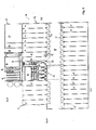
- Fig. 6 the ground plan of the BMKW 10 is shown.
- Fig. 7 shows an enlarged partial area of the floor plan of Fig. 10 , in which a power and heat generation plant of the BMKW is shown.
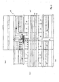
- Fig. 8 shows another part of the plan of Fig. 6 , in which a delivery and loading area is shown enlarged.
- Fig. 9 shows a plan view of the upper floor of the BMKW 10.
- the BMKW 10 is divided into a base portion 12 and an expansion portion 14.
- the base portion 12 includes 18 fermenters of the garage type, which are arranged in two rows, in the illustration of Fig. 5 in a northern and a southern row. Located between the two rows of fermenters 16 a Fermentervorplatz 18, to which the gates 20 of the fermenter 16 open. It should be noted that for the sake of clarity, not all the fermenters 16 and fermenter ports 20 are provided with reference numerals in the figures.
- the base portion 12 includes a power and heat generating plant 22, which in Fig. 7 shown enlarged and described in more detail below.
- the base portion 12 includes a delivery and loading area 24, which in Fig. 8 is shown enlarged and also described in more detail below.
- the entire base portion 12 is enclosed by a hall structure to which in particular a Fermentervorplatz (FVP) -Hallenabites 26 and a delivery and Verlade Schlenabites 28 belongs, as in particular Fig. 1, 4th and 5 easy to recognize.
- FVP Fermentervorplatz
- the entire hall construction or enclosure of the base section 12 is vented by a large central venting system, so that there is always a slight negative pressure relative to the atmospheric pressure inside the hall construction.
- the expansion section 14 essentially consists of 11 additional fermenters 16 'and an extension of the FVP hall section 26.
- the expansion section 14 serves to provide, if necessary, up to 11 additional fermenters 16'.
- the BMKW 10 has a modular design, which is advantageous for achieving an optimal end configuration, because the exact biogas yield depends on a variety of factors, including the nature of the existing fresh mass, and is not theoretically accurately predictable.
- the northern and southern fermenter rows are connected by a technology bridge 30, which in particular in Fig. 5 . 6 and 9 you can see.
- the technology bridge 30 straddles the FVP 18 at a height that allows wheel loaders, of which in Fig. 5 two shown as examples are able to drive under it even with fully extended loading shovel, without that they can touch and damage the technology bridge.
- the upper floor of the BMKW 10 comprises three film gas storage 32 in the base section 12 and two further film gas storage 32 'in the expansion section 14.
- the film gas storage 32 are in the cross-sectional views of Fig. 5 and 15 easy to recognize. They take on the manner described in more detail below the biogas, which is generated in the fermenters 16 and 16 '.
- the upper floor comprises five percolate circulation tanks (PUT) 34 in the base section 12 and four PUTs 34 'in the expansion section 14, which are also shown in the cross-sectional views of FIG Fig. 5 good to see.
- PUT 34 is located above each of three fermenters 16 and receives percolate from them, which is collected at the bottom of the fermenters and pumped into the PUT 34.
- percolate refers to the liquid, manure-like component of the fermentation substance.
- an exhaust gas cooling room 31 located on the upper floor, an exhaust gas cooling room 31, a southern technical room 36 and a northern technical room 38, which are interconnected by the technology bridge 30.
- an exhaust gas cooling room 31 located on the upper floor, an exhaust gas cooling room 31, a southern technical room 36 and a northern technical room 38, which are interconnected by the technology bridge 30.
- the Fermentervorplatz (FVP) 18 is located in the center of the BMKW 10. It serves as a transport route for fresh mass to the respective fermenters 16, 16 'or of digestate substance from the fermenters 16, 16'. In addition, it serves as Anmisch Structure on which the contents of a fermenter is spread, taken from about a fifth to a quarter as digestate and to compensate for this withdrawal and the loss of mass resulting from the gasification, about one-third is supplemented by fresh mass and mixed with the old fermentation mass.
- This work can be done on the FVP 18 by a large wheel loader, as in Fig. 5 is shown schematically.
- a grated gutter into which seepage fluids and released percolate flow.
- the gutter has a collection well (not shown) from which the resulting liquids are conveyed to one of the PUTs 34 via a percolate loop (not shown).
- the delivery and loading area 24 is in Fig. 8 shown enlarged in plan.
- four delivery bunkers 42 are provided in the embodiment shown, which are housed by the delivery and loading area Hall section 28.
- a truck can maneuver backwards into the hauled-in delivery bunker and tip or dump the fresh bulk cargo into the delivery bunker 42 there. Since there is a slight underpressure throughout the delivery and loading area 24, hardly any unpleasant odors leave the enclosure to the outside.
- Each delivery bunker 42 has a downwardly tapered bottom, at the lowest point of one or more double screw conveyor (not shown) are provided which promotes the fresh mass horizontally to a bucket elevator (not shown), which conveys the fresh mass onto a conveyor belt 44 , or directly on a lower conveyor belt.
- the fresh mass is dropped into a Frischmassebunker 46. Since the fresh mass is conveyed from four or more different bunkers on the same conveyor belt 44 and thrown onto the same heap in the fresh mass bunker 46, the fresh mass is automatically mixed.
- the Frischmassebunker 46 is an elongated chamber that connects the delivery and loading area 24 with the Fermentervorplatz 18, in particular in Fig. 6 you can see.
- the Frischmassebunker 46 has a floor heating, with the fresh mass already on a Temperature of 42 ° C is heated so that the fermentation mass within a fermenter 16, 16 ', which is supplemented by the fresh mass, is not cooled by this, so that the fermentation process after closing the fermenter 16 starts again quickly and possibly even already weakly aerobic prehydrolysis can take place, which shortens the fermentation time and increases the system performance (throughput of fermentation substrate) and the efficiency of the plant.
- the fresh mass bunker 46 has a dual function. First, it serves as an intermediate or buffer storage for loose fresh mass. On the other hand, it serves as a transport path between the delivery and loading area 24, ie the periphery of the BMKWs 10, and the centrally located Fermentervorplatz 18.
- a push plate or slider arranged (not shown) of each new from above poured bulk loose fresh mass towards the Fermentervorplatz 18 pushes. Then the slide is moved back to make room for new fresh mass.
- This sliding mechanism ensures that the fresh mass is pushed out of the fermenter in the same order in which it was introduced at the entrance into the Frischmassebunker 46, on the side of the Fermentervorplatzes 18 out of it. This means that the fresh mass that reaches the Fermentervorplatz 18, always about the same age and therefore of constant quality, which is advantageous for the subsequent fermentation.
- the delivery and loading area 24 comprises a section for the delivery and transport of structural or bale material, in particular for straw.
- This section for delivering and transporting bale material comprises a preparation space 48, a bale delivery space 50, a digestion area 52 and an intermediate storage 54.
- this area of the delivery and loading area 24 will be described with reference to straw as a highly lignified, bale-shaped structural material. but it is understood that this section can also be used for the delivery, processing and onward transport of other bale-shaped structural material.
- a crane (not shown) is mounted on a track so that it can pick up and drop straw bales in each of the spaces 48-54.
- the bales of straw are delivered to the straw delivery room 50 and transported by the crane (not shown) to the intermediate storage 54.
- the digestion region 52 Before the straw is conveyed to the fermentor forecourt 18, it is pretreated in the digestion region 52, namely digested.
- the digestion of the straw is necessary because the Straw is heavily lignified, and the bacteria in the fermenter 16 due to the lignin-crusted cellulose only very poorly get to the lignin trapped nutrients.
- the straw can be digested in different ways.
- the straw may be chemically disrupted by soaking it in a container containing water, a water-caustic solution or a water-acid solution.
- the soaking causes the lignin, which has largely enclosed the cellulose, to be partially dissolved.
- the cellulose is no longer hidden behind a lignin crust, but accessible to the hydrolysis and the bacteria.
- the straw in the digestion region 52 may be otherwise disrupted, for example mechanically using a hammer mill or by being subjected to thermal pressure, i. heated to 180 ° C to 250 ° C for five to ten minutes at high pressure, for example, 20 to 30 bar.
- thermal pressure i. heated to 180 ° C to 250 ° C for five to ten minutes at high pressure, for example, 20 to 30 bar.
- the lignin solidifies again, but in the form of very small globules with gaps between them, which open the way for the autohydrolytic, organic acids and for the anaerobic bacteria to the nutrients of the straw.
- Another embodiment is an extension of the thermal printing treatment in which the pressure in the corresponding container is suddenly reduced, whereby the water evaporates in the straw structures and expands very rapidly.
- the lignin structures are torn and the nutrients for the anaerobic bacteria are exposed. Further details of the straw digestion are given in the following section.
- a roller conveyor 56 onto which individual bales of straw and / or straw bales are laid by the crane (not shown) and which conveys the straw bales to the fermentor forecourt 18 through a straw channel 58 arranged parallel to the fresh meal hopper 46 (see FIG Fig. 6 ).
- both the loose fresh mass and the fresh bale mass are transported by stationary conveyor technology from the delivery and loading area 24 to the fermenter forecourt 18.
- stationary conveyor technology makes the Frischmassebunker 46 and the straw channel 58, the connection between the central Fermentervorplatz 18 and the peripheral delivery and loading area 24 ready, and this transport is done completely in the housed BMKW 10.
- the transport with the stationary conveyor technology is suitable for high throughputs and in particular faster, more space-saving and less expensive than a delivery with wheel loaders.
- the straw channel 58 and the Frischmassebunker 46 ends at a central location of the fermenter forecourt 18, so that the paths between the fermentervorplatznessen end of Frischmassebunkers 46 and straw channel 58 and the fermenter 16 to be supplied are generally short.
- the digestion of the straw in the digestion region 52 makes it possible to use straw, despite its high lignin content, as a fermentation substrate. This is extremely advantageous because straw in crop production anyway incurred, and not enough use for this exists.
- the BMKW 10 is designed for renewable raw materials, it makes sense to grow in the vicinity of the BMKW 10 specifically for use in the BMKW 10 suitable raw materials, which, however, are generally not intended for food. However, this poses a certain conflict of objectives because a certain proportion of the limited land available is always reserved for food production.
- the use of straw as a fermentation substrate is a very attractive solution, since straw, which is produced during grain production, allows the simultaneous production of food and biomass suitable for power plants.
- straw has another advantage.
- the filling level in fermenters is limited by the pressure that results at the bottom of the fermenter: this pressure must always be so low that the fermentation substrate is still permeable to percolate.
- this pressure must always be so low that the fermentation substrate is still permeable to percolate.
- the entire usual filling level can be layered on this layer of fermentation substance, since the straw bale layer even at the pressure then permeable to Percolate is.
- This lowermost straw layer thus represents an additional amount of fermentation substrate which can be used in a fermenter, so that the Plant performance (room capacity measured in new substrate per fermenter and day) is significantly increased.
- the straw bales are placed in packages of eight straw bales on the roller conveyor 56, which are two bales wide and four bales high. These packages are transported as a whole through the straw channel 58 and lifted at the end of the Fermentervorplatz 18 by a converter (not shown) and passed to a wheel loader or forklift, which also receives the packages as a whole or in two parts and brings to the fermenter. From these packages can be relatively easily and quickly built said bottom straw bale layer.
- a digestate bunker 60 is provided which extends parallel to the fresh material bunker between the Fermentervorplatz 18 and the delivery and loading area 24.
- the digestate bunker 60 has at its Fermentervorplatz the end facing a Schütttrog 62 for digestate, which forms the entrance into the Gärrestebunker 60.
- this Schütttrog 62 fermentation residues are tilted by a wheel loader. From there they are pressed into the digestate bunker by means of a screw conveyor. Due to the discontinuous reprints of more and more fermentation residues, the mass is slowly transported through the digestate bin 60 to the other end, where they are transported by further screw conveyors from the digestate bunker 60.
- the digestate bunker 60 has a triple function. On the one hand, it serves as a transport path between the fermenter forecourt 18 in the center of the BMKW 10 and the delivery and loading area, with similar advantages, as they have been described with respect to the Frischmassebunker 46 and the straw channel 58. On the other hand, the digestate bunker 60 also serves as a thermophilically operated secondary fermenter and acts more or less like another fermenter. Therefore, the digestate bunker 60 is also connected to the biogas system.
- the digestate bunker 60 serves as a buffer for fermentation residues. It is so dimensioned that it holds at least as much digestate as can be accumulated in two days. This makes it possible to carry out the removal of the resulting digestate on weekdays, so that the removal is not hindered by truck driving restrictions.
- a switch 64 is provided, which makes it possible to transport the fermentation residues either directly via a conveyor belt 66 to loading silos 68, or to take the detour via a dehydrating device 70.
- the dehydrating device 70 is a screw press which is suitable for pressing water or percolate from the fermentation residues and introducing them into one of the PUTs 34. Whether the detour is taken via the dehydrator 70 depends on the current need for percolate.
- the loading silos for digestate 68 are high silos, which are arranged on trapezoidal frames, so that a truck can drive under the silos 68 and thus can be easily loaded.
- a conventional drying plant for example a drum or belt dryer (not shown) is provided, which is suitable for drying the fermentation residues to less than 25%, preferably to 15%, water content.
- the heat for the drying plant is preferably provided by the waste heat from the generator sets.
- a gasification plant (not shown) is provided, in which the dried fermentation residues are subjected to a so-called wood gasification, in which flammable wood gas (lean gas) is obtained from the dried digestate by pyrolysis or partial combustion under air deficiency. This wood or lean gas is fed after the removal of the tar resulting from the wood gas by any known method in the biogas system and can then be used without any problems as a fuel for the gasoline engines.
- the energy content of the wood gas reduces the demand for biogas by up to 20%, possibly even more, so that for the same power output up to 20% or possibly up to 30% less substrate must be used for the fermentation. As a result, the profitability of the system as a whole increases considerably.
- the straw is delivered in the delivery and loading area 24 and digested in the digestion area 52 and possibly additionally in the staging area 48.
- straw in this embodiment of the invention is straw as LHNawaRo delivered in bale form and also open in bale shape, to be finally introduced in bale shape in the garage fermenter 16.
- the bales preferably have a density of over 200 kg / m 3 , which can be produced only with ultra-high pressure balers.
- the advantage of such a high density of straw bales is that then the capacity of a truck is optimally utilized both in terms of the permissible weight of the load and the possible volume of the load, so that the straw can be delivered over longer distances to economic conditions.
- part of the straw can be put into the digestion form "grinding" and / or into the digestion form "thermal pressure hydrolysis".
- the combination of the various forms of digestion is particularly advantageous because each has its advantages and disadvantages for the practice. The combination achieves the best overall effect.
- the milled straw leads to a particularly high gas yield, but the proportion in relation to the fresh mass is limited insofar as the powdered straw wetted by percolate forms a sticky mass, which must be mixed because of the handling with sufficient fresh mass.
- the fermentation substrate as a whole consists of ground straw.
- between 5% and 35% of the straw used in total is ground and thereby mechanically digested.
- the perforation of straw bales serves to make the interior of the straw bale accessible for soaking, for saturated steam treatment and for subsequent soaking in percolate.
- the straw bales are perforated from two sides, as with reference to FIG Fig. 10 is explained in more detail.
- Fig. 10 shows above a perspective view of a straw bale 72, in which on the underside 74 is looked.
- the lower figure shows a perspective view of the same straw bale 72, is looked at on the top 76.
- the straw bale 72 is perforated by a first set of holes 78 that do not pass through the entire bale 72.
- the straw bale 72 is perforated from the top 76 with a second set of holes 80 that also do not pass through the entire straw bale 72.
- the holes 78 and 80 are offset from each other so that the holes of the first set 78 and the holes of the second set 80 are separated by material bridges.
- suitable containers are provided for soaking straw bales, which are not shown in the illustration.
- the size of the container for soaking are matched to the dimensions of the straw bales, so that the soaking can be carried out space-saving and efficient.
- a device for saturated steam treatment is provided in the digestion region 52 or in the preparation space 48.
- various facilities for saturated steam treatment are described, which can be used in the system shown or a modified system.
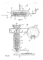
- Fig. 11 shows a schematic cross-sectional view of a simple structure of a device 82 for saturated steam treatment.
- the device 82 comprises a pressure vessel 84 with a lid 83 which is articulated via a hinge 85 pivotally mounted on the pressure vessel 84.
- a feeding device for the straw is indicated schematically and designated by reference numeral 87.
- the feeder 87 may be formed by, for example, a conveyor belt or a roller conveyor.
- the feeder 87 may be rails on which a loose material container 89 may be pushed into the pressure vessel 84.
- the container 89 is permeable to water vapor, but is capable of holding the loose material and may be, for example, an open-topped lattice container or basket.
- the lid 83 of the pressure vessel 84 can be closed by a closing mechanism 91.
- the lid 83 is pivoted to open the pressure vessel 84 inwardly, as for example in Fig. 14 can be seen, so that the lid 83 is pressed by the pressure in the interior of the pressure vessel 84 in the closed position and thereby easier sealed.
- the pressure vessel 84 is connected to a supply line 93 and a supply valve 95, through which saturated steam 102 at a pressure of up to 30 bar and a temperature of up to 250 ° C from a steam reservoir (not shown) are introduced into the pressure vessel 84 can. Further, the pressure vessel 84 is connected to an outlet line 97 with an outlet valve 98, through which the steam can be discharged from the pressure vessel 84 after the saturated steam treatment. Further, a compressor 100 is arranged in the outlet conduit 97, with which the saturated steam 102 in the reservoir (not shown) can be returned.
- the saturated steam treatment method will be described with reference to the saturated steam treatment device 82 of FIG Fig. 11 explained.
- the lignin-containing material 106 is introduced as a bale or loose material in a container as in the container 89 in the pressure vessel 84 and the pressure vessel 84 is closed. Thereafter, the valve 95 is opened in the supply line 93, so that hot steam at a temperature of 180 ° C to 250 ° C and a high pressure of between 20 and 30 bar from a steam reservoir (not shown) is introduced into the pressure vessel 84.
- the introduced saturated steam is in Fig. 11 indicated schematically and designated by the reference numeral 102.
- the lignin-containing material 106 is exposed to the saturated steam 102 for 5 to 15 minutes.
- the lignin in the material is melted but not released from the material.
- the material e.g. the straw was soaked in the second step above, because the water is already present in the material and only needs to be heated, which shortens the treatment time.
- the saturated steam is discharged through the outlet conduit 97 from the pressure vessel 84.
- This release of pressure preferably occurs abruptly, so that the pressure decreases by at least 80% within 5 seconds or less. Due to the rapid lowering of the pressure, the water in the structures of the lignin-containing material abruptly evaporates and expands rapidly.
- the lignin structures of the straw are torn so that the nutrients (cellulose and arabinoxylan) become accessible to aqueous organic acids and the anaerobic bacteria.
- the lignin-containing material 106 is removed from the pressure vessel 84, and it cools down. Upon cooling, the molten lignin hardens again. However, upon solidification of the lignin, the original planar structures do not re-form, but rather coagulate in a droplet structure that allows spaces through which first organic acids and then bacteria can pass to the cellulose and arabinoxylan (hemicellulose).
- Fig. 11 Basically, the structure of the saturated steam treatment device 82 can be modified in a variety of ways, and some examples of such modifications are given below. In this case, identical or functionally identical components with the same reference numerals as in Fig. 11 and their description is not repeated.
- Fig. 12 shows a structure of a device for saturated steam treatment, which is designed for a quasi-continuous processing of loose material.
- a container 89 is provided for loose material 106 inside the pressure vessel 84, but this is permanently installed in the pressure vessel 84.
- a pressure-resistant slide 108 is opened so that the lignin-containing material 106 falls from a funnel 110 into the container 88. If there is a sufficient amount of material 106 in the container 89, the pressure resistant slide 108 is closed and the saturated steam treatment takes place in the same manner as described with reference to FIGS Fig. 11 has been described.
- a saturated steam reservoir 102 is shown which has a heater 114.
- the steam is discharged via the outlet conduit 97 and forced into the reservoir 112 via the compressor 100. Thereafter, another pressure-resistant slide 108 is opened at the lower end of the container, and the digested loose material 106 falls onto a conveyor belt 116 for further transport.
- a liquid mass 117 which is referred to as "slurry" and which is discharged via a further line 118 and passed via a line 120 in the percolate circulation tanks (not shown).
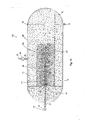
- Fig. 13 shows a further embodiment 122 of a device for saturated steam treatment, which is designed especially for the treatment of bale material, in particular straw bales 72.
- the structure is basically similar to the structure of Fig. 11 and will not be described again. The main difference, however, is that a spit or spike 124 is provided which has an inner cavity 126 and nozzle-like openings 128 connected to this inner cavity 126.
- the inner cavity 126 is in fluid communication with the supply line 93.
- the saturated steam treatment device 122 of Fig. 13 In operation of the saturated steam treatment device 122 of Fig. 13 is a straw bale 72 and 106 via the feed device 87, which is formed in the illustrated embodiment by a roller conveyor, in the illustration of Fig. 13 from the right into the pressure vessel 84 introduced and skewered on the skewer 124. Then, the pressure vessel 84 is closed as before, and the saturated steam 102 is injected via the supply line 93, the inner cavity 126 of the spit 124 and the nozzle-like openings 128 in the straw bale 72. This ensures that the interior of the straw bale 72 comes into effective contact with the saturated steam. Namely, the saturated steam as in Fig.
- the five pressure vessels 84 includes, similar to the device 122 of Fig. 13 are provided with spits 124. However, in the device 130 of Fig. 14 the pressure vessels 84 are arranged vertically so that the bales of straw can be introduced into the pressure vessels from above with a crane 132.
- the crane 132 comprises a trolley 134 and a rack 136 having an upper bale 138 and a lower grab 140 are formed for a lower bale.
- All pressure vessels 84 of Fig. 14 are connected via a pipeline to the same pressure reservoir 112. It will be similar to in Fig. 13 the saturated steam 102 is introduced via the feed line 92 through the spit 124 and through the straw bales 72 into the pressure vessel 84.
- Fig. 14 The training of Fig. 14 is designed for a high throughput plant where saturated steam treatment can be carried out very efficiently.
- the pretreated bales are soaked in percolate, which is a weakly acidic solution.
- the bales may be soaked in a weakly alkaline solution such as caustic soda.
- the bales are heated to about 40 ° C, which can be accomplished, for example, that the straw channel 46 (s. Fig. 8 ) is heated by waste heat of the gas Otto engines.
- a weakly aerobic prehydrolysis is initiated, through which the subsequent anaerobic bacterial fermentation is further accelerated.
- the anaerobic bacteria are at the same place of fresh material, which is also beneficial.
- the straw digestion process described herein achieves that the pretreated material in the fermenters provides substantial gas yield with moderate residence times, and does so without adding additional enzymes, fungi or yeasts.
- the natural acid content of the straw (around 3 to 4%) dissolves the solid cellulose and converts it into an aqueous solution (autohydrolysis).
- the biogenic polymers are biochemically cleaved by the action of the organic acid chemically and / or by the influence of bacteria in low-molecular compounds (monosaccharides, amino acids, short-chain peptides, long-chain fatty acids, glycerol). These are present in water-dissolved form at the end of the phase. However, this happens without first enzymes, bacteria or yeasts must be added.
- the lignocellulosic material in this embodiment is left alone to autohydrolysis and bacterial hydrolysis.
- LHNawaRo is mixed with liquid manure or solid manure before being introduced into the fermenter, but it may already be sufficient if LHNawaRos and solid manure are stacked in alternating layers in the fermenter, optionally with intervening layers of other, non-lignified NawaRos, wherein the urea of the upper layers of solid manure with the percolate penetrates into the layer containing the lignin-containing material and thus at least partially dissolves the two-dimensional lignin structures. This represents a very simple case of chemical disruption.
Abstract
Die vorliegende Erfindung betrifft eine Biogasanlage und ein Verfahren zur Erzeugung von Biogas aus Stroh. Es sind Mittel zur Vorbehandlung des Strohs vorgesehen, um einen mechanischen Aufschluß und ggf. chemischen und/oder thermischen Aufschluss desselben zu bewirken bevor er in einen Fermenter eingebracht wird, in dem eine anaerobe bakterielle Vergärung stattfindet.The present invention relates to a biogas plant and a method for producing biogas from straw. Means are provided for pretreating the straw in order to effect mechanical digestion and, if appropriate, chemical and / or thermal decomposition thereof before it is introduced into a fermenter in which anaerobic bacterial fermentation takes place.
Description
Die vorliegende Erfindung betrifft eine Biogasanlage und insbesondere ein Biomasse-Kraftwerk zur Biogaserzeugung nach dem Oberbegriff von Anspruch 1 und ein Verfahren zur Erzeugung von Biogas aus Stroh.The present invention relates to a biogas plant and more particularly to a biomass power plant for biogas production according to the preamble of claim 1 and to a process for producing biogas from straw.
Gegenwärtig findet Stroh in Biogasanlagen praktisch keine Anwendung als Gärsubstrat; in Biogasanlagen gelangt es lediglich indirekt in kleinen Mengen als im Festmist enthaltene Einstreu. Es besteht nämlich aus Gründen, die im Folgenden erläutert werden, ein technisches Vorurteil gegenüber der Verwendung von Stroh als Gärsubstrat.At present, straw in biogas plants is practically no use as a fermentation substrate; In biogas plants, it is only indirectly transported in small quantities as litter contained in the solid manure. For reasons explained below, there is a technical prejudice against the use of straw as a fermentation substrate.
Gegenwärtig sind in Deutschland über 3.500 Naßfermentationsanlagen im Einsatz, denen lediglich rund 20 Anlagen zur Feststoffvergärung (Trockenvergärung) von nachwachsenden Rohstoffen gegenüberstehen. Bei Naßfermentationsanlagen kommt eine Verwendung von Stroh schon deshalb nicht in Betracht, weil die nasse Gärsubstanz mit Paddelrädern bzw. Propellern umgerührt werden muß und sich das Stroh dabei um die Paddel bzw. Propeller wickeln würde. Deshalb wird in Naßfermentationsanlagen auch kaum strohenthaltender Festmist verwendet, sondern vornehmlich Gülle. Wenn man das Stroh häckseln würde, um dieses mechanische Problem zu umgehen, schwimmt das gehäckselte Stroh auf und mischt sich daher mit dem nassen Gärsubstrat nicht. Außerdem verstopft es dabei in der Regel die Ab- bzw. Überläufe der Nassfermenter. Schon aus diesen Gründen kommt Stroh als Gärsubstrat für Naßfermentationsanlagen gegenwärtig nicht in Betracht.At present, more than 3,500 wet fermentation plants are in use in Germany, compared with only about 20 plants for the fermentation of solids (dry fermentation) of renewable raw materials. In Naßfermentationsanlagen use of straw is therefore out of the question, because the wet fermentation substance must be stirred with paddle wheels or propellers and the straw would wrap around the paddles or propellers. Therefore, hardly any straw-containing solid manure is used in wet fermentation plants, but primarily manure. If you chop up the straw to avoid this mechanical problem, the chopped straw floats and does not mix with the wet fermentation substrate. In addition, it usually clogs the drains or overflows of the wet fermenter. For these reasons straw is currently out of the question as a fermentation substrate for wet fermentation plants.
Bestehende Biomasse-Kraftwerke bzw. Biogasanlagen zur Biogaserzeugung nach dem Feststoff Vergärungsverfahren sind typischerweise kleine landwirtschaftliche Anlagen mit zwei bis sechs Fermentern. Gemäß dem erst kürzlich erschienenen Endbericht "Monitoring zur Wirkung des novellierten Erneuerbare-Energien-Gesetzes (EEG) auf die Entwicklung der Stromerzeugung aus Biomasse", der im Auftrag des Bundesministeriums für Umwelt, Naturschutz und Reaktorsicherheit (BMU) erstellt wurde, hat die Trockenvergärung noch nicht den Stand der Marktreife erreicht. Die in Betrieb befindlichen Anlagen werden dort vielmehr als Demonstrationsanlagen angesehen (siehe Seite 52,
Anstelle von Stroh werden in bekannten Feststoffvergärungsverfahren statt dessen herkömmlicherweise vorwiegend Bioabfälle sowie Rinder- und Schweinefestmist und Hühnertrockenkot verwendet. Außerdem werden hauptsächlich wenig lignifizierte nachwachsende Rohstoffe (NawaRos), wie beispielsweise frisch geerntetes Gras, Silagen aus Gras, Getreide-Ganzpflanzenschnitt und Mais-Ganzpflanzenschnitt sowie Heu, Kartoffeln und Rübenhackschnitzel eingesetzt.Instead of straw, conventionally used in known solidification processes instead of it mainly biowastes and cattle and Schweinefestmist and Hühnertrockenkot. In addition, low lignified renewable raw materials (NawaRos), such as freshly harvested grass, silage from grass, whole crop cut corn and corn whole crop cut and hay, potatoes and beet chips are mainly used.
Da die gegenwärtig bekannten Biogasanlagen mit Feststoffvergärung typischerweise im ländlichen Raum, beispielsweise auf einem Bauernhof stehen und nur einen verhältnismäßig kleinen Durchsatz haben, wird der Bedarf an Gärmasse üblicherweise aus dem eigenen Bestand des Landwirtes und möglicherweise der Nachbarbetriebe gedeckt. Für größere Feststoffvergärungsanlagen als bisher üblich stellt die Beschaffung geeigneter Gärsubstrate in ausreichender Menge und zu wirtschaftlichen Bedingungen jedoch ein Problem dar.Since the currently known biogas plants with fermentation of solid matter are typically located in rural areas, for example on a farm and have only a relatively small throughput, the demand for fermentation mass is usually covered by the farmer's own holdings and possibly the neighboring farms. For larger solid fermentation plants than hitherto usual, however, the procurement of suitable fermentation substrates in sufficient quantity and at economic conditions is a problem.
Der vorliegenden Erfindung liegen die Ideen für eine Biogasanlage, insbesondere für ein Biomasse-Kraftwerk und für ein Verfahren zur Erzeugung von Biogas zugrunde, die das Problem lösen, geeignete Gärsubstrate in ausreichenden Mengen insbesondere für größere, im industriellen Maßstab arbeitende Anlagen zu wirtschaftlichen Bedingungen zu beschaffen und zu verarbeiten.The present invention is based on the ideas for a biogas plant, in particular for a biomass power plant and for a process for the production of biogas, which solve the problem of obtaining suitable fermentation substrates in sufficient quantities, especially for larger, industrial-scale plants to economic conditions and process.
Diese Ideen werden mit einer Biogasanlage mit den Merkmalen des Anspruchs 1 und mit dem Verfahren mit den Merkmalen des Anspruchs 10 realisiert. Vorteilhafte Weiterbildungen sind in den abhängigen Ansprüchen angeben.These ideas are realized with a biogas plant having the features of claim 1 and with the method having the features of
Erfindungsgemäß ist bei der Biogasanlage eine Einrichtung zum mechanischen Aufschluß und ggf. chemischen und/oder thermischen Aufschluss von Stroh vorgesehen. Durch den Aufschluß von Stroh läßt sich entgegen der üblichen Meinung auch mit diesen ein erheblicher Gasertrag erzielen. Dadurch wird die Biogaserzeugung, insbesondere die Biogaserzeugung nach dem Feststoffvergärungsverfahren, für eine neue Klasse nachwachsender Rohstoffe zugänglich, denn Stroh steht in großen Mengen zur Verfügung steht und ist preisgünstig erhältlich. Das Stroh kann als Ergänzung zur herkömmlichen Frischmasse, wie beispielsweise Silage aus Grünschnitt, Silage aus ganzen Getreidepflanzen etc., verwendet werden und stellt so die Versorgung selbst einer Vielzahl großer und sehr großer Biomasse-Kraftwerke, mit beispielsweise 20 oder mehr Fermentern und einer jeweiligen elektrischen Leistung von über 5.000 kW zu wirtschaftlichen Bedingungen sicher.According to the invention, a device for the mechanical digestion and possibly chemical and / or thermal digestion of straw is provided in the biogas plant. By the digestion of straw can be contrary to the usual opinion with these achieve a significant gas yield. As a result, biogas production, in particular biogas production after the solidification process, becomes accessible to a new class of renewable resources, Because straw is available in large quantities and is available at low cost. The straw can be used as a supplement to the conventional fresh mass, such as silage from green waste, silage from whole cereal crops, etc., thus providing itself to a variety of large and very large biomass power plants, with for example 20 or more fermenters and a respective electric Power of over 5,000 kW to economic conditions safely.
Vorzugsweise umfaßt die Einrichtung zum thermischen Aufschluß von Stroh eine Einrichtung zur Sattdampfbehandlung. Die Einrichtung zur Sattdampfbehandlung umfaßt vorzugsweise einen Druckbehälter und Mittel, die geeignet sind, im Druckbehälter einen Wasserdampf zu erzeugen, mit einem Druck, der zwischen 20 und 30 bar liegt und einer Temperatur, die zwischen 180°C und 250°C liegt. Eine Sattdampfbehandlung findet bei den beschriebenen Drücken und Temperaturen statt und dauert typischerweise 5 bis 15 Minuten. Die Funktion der Sattdampfbehandlung soll am Beispiel von Weizenstroh beschrieben werden.Preferably, the means for thermal digestion of straw comprises a device for saturated steam treatment. The device for saturated steam treatment preferably comprises a pressure vessel and means adapted to generate a water vapor in the pressure vessel, with a pressure which is between 20 and 30 bar and a temperature which is between 180 ° C and 250 ° C. Saturated steam treatment takes place at the pressures and temperatures described and typically lasts for 5 to 15 minutes. The function of the saturated steam treatment will be described using the example of wheat straw.
Weizenstroh besteht zu etwa 40 % aus Cellulose, zu 23 % aus Arabinoxylan (Hemicellulose) und zu 21 % aus Lignin, wobei alle drei Hauptkomponenten eine dichtgepackte Struktur einnehmen. Das wesentliche Hindernis für die biochemische Verwertung der Cellulose und der Hemicellulose ist das für Mikroorganismen unverdauliche Lignin, das den Bakterien den Weg zur Cellulose und zur Hemicellulose versperrt. Bei der Sattdampfbehandlung werden die Ligninstrukturen aufgeweicht bzw. geschmolzen, aber während der verhältnismäßig kurzen Behandlungsdauer im Wesentlichen nicht aus den Halmen ausgelöst. Nach der Sattdampfbehandlung erstarrt das Lignin wieder. Beim Erstarren des Lignins bilden sich jedoch aufgelockerte tröpfchenartige Ligninstrukturen, die ausreichend Zwischenräume lassen, durch die zunächst wässrigen organischen Säuren und dann die Bakterien an die Cellulose und das Arabinoxylan gelangen können, die diese durch die bekannte anaerobe vierstufige Vergärung zersetzen.Wheat straw consists of about 40% cellulose, 23% arabinoxylan (hemicellulose) and 21% lignin, with all three main components taking on a tightly packed structure. The main obstacle to the biochemical utilization of cellulose and hemicellulose is lignin, which is indigestible to microorganisms and blocks the bacteria from accessing cellulose and hemicellulose. In saturated steam treatment, the lignin structures are softened or melted, but during the relatively short treatment time essentially not triggered from the stalks. After the saturated steam treatment, the lignin solidifies again. However, when the lignin solidifies, lumped droplet-like lignin structures are formed which leave enough interstices through which firstly aqueous organic acids and then the bacteria can reach the cellulose and arabinoxylan, which decompose them by the known four-stage anaerobic fermentation.
Bei der hier beschriebenen Sattdampfbehandlung wird das Lignin also vornehmlich in seiner mikroskopischen Struktur verändert, es wird aber nicht aus den Strohhalmen herausgelöst. Insbesondere bleibt die Struktur der Strohhalme als solche dabei erhalten. Dies stellt einen Unterschied zur Thermodruckhydrolyse dar, die unter grundsätzlich ähnlichen Bedingungen, jedoch für längere Zeiträume durchgeführt wird, und bei der eine echte Hydrolyse stattfindet, also eine Auflösung vormals fester bzw. trockener Stoffe in Wasser. Durch eine Thermodruckhydrolyse wird die Struktur der Strohhalme aufgelöst, und es ergibt sich eine sirupartige Suspension.In the saturated steam treatment described here, the lignin is thus changed primarily in its microscopic structure, but it is not dissolved out of the straws. In particular, the structure of the straws remains as such. This represents a difference to the thermal pressure hydrolysis, which is carried out under basically similar conditions, but for longer periods, and in which a real hydrolysis takes place, that is, a dissolution of previously solid or dry substances in water. By a thermal pressure hydrolysis The structure of the straws is dissolved, resulting in a syrupy suspension.
In einer vorteilhaften Weiterbildung umfaßt die Einrichtung zum Aufschluss von Stroh einen Behälter zum Einweichen desselben vor der Sattdampfbehandlung, beispielsweise in Wasser. Wenn das eingeweichte Stroh einer Sattdampfbehandlung unterzogen wird, verdampft das eingezogene Wasser schlagartig, wodurch Ligno-Cellulosestrukturen zerreißen und die Cellulose noch besser für die Bakterien zugänglich wird.In an advantageous development, the device for digesting straw comprises a container for soaking it before the saturated steam treatment, for example in water. When the soaked straw is subjected to saturated steam treatment, the drawn-in water evaporates abruptly, rupturing ligno-cellulose structures and making the cellulose even more accessible to the bacteria.
In einer vorteilhaften Ausführungsform ist eine Einrichtung zum mechanischen Zerkleinern des Strohs vorgesehen, durch die das Stroh vor der Sattdampfbehandlung mechanisch aufgeschlossen werden kann, beispielsweise durch Häckseln. Dies trägt weiter zum Auflösen der Ligninstrukturen bei und erleichtert die nachfolgende Vergärung.In an advantageous embodiment, a device for mechanical comminution of the straw is provided, through which the straw can be mechanically digested before the saturated steam treatment, for example by shredding. This further contributes to the dissolution of the lignin structures and facilitates the subsequent fermentation.
Erfindungsgemäß findet eine Vermahlung des Strohs, vorzugsweise in einer Hammermühle, statt. Diese Aufschlussform zerstört die Ligninstrukturen mechanisch. Eine Vermahlung allein ist jedoch bei der Nutzung des Feststoffvergärungsverfahrens nicht sinnvoll, weil sich sonst ein teigartiger Brei bilden würde, der die Gärmasse verklebt und eine Perkolation verhindert.According to the invention, the straw is ground, preferably in a hammer mill. This form of disruption mechanically destroys the lignin structures. Milling alone, however, is not useful when using the Feststoffvergärungsverfahrens because otherwise a doughy porridge would form, which adheres to the digestate and prevents percolation.
Alternativ kann das Stroh auch in Ballenform aufgeschlossen werden, was insbesondere dessen Transport und Handhabung wesentlich erleichtert, wie unten näher erläutert wird. Da die Struktur beispielsweise von Strohhalmen unter der Sattdampfbehandlung erhalten bleibt, behalten auch Strohballen ihre Form unter der Sattdampfbehandlung bei und können nach dieser einfach und effizient transportiert werden. Ein besonderer Vorteil von Ballen besteht ferner darin, daß diese zuunterst in einen Garagenfermenter geschichtet werden können, wodurch sich die Füllhöhe des Fermenters steigern läßt. Prinzipiell ist die Füllhöhe des Fermenters dadurch begrenzt, daß ab einer gewissen Höhe des Substrats im Fermenter der Druck an dessen Boden so hoch wird, daß das Substrat zu stark verdichtet wird, um Perkolat durchsickern zu lassen. Strohballenschichten, die zuunterst in einen Fermenter eingebracht werden, sind jedoch weitaus druckstabiler als herkömmliches Gärsubstrat. Selbst unter hohem Druck ist die Strohballenschicht noch durchlässig für Perkolat, so daß die übliche Füllhöhe im Fermenter noch auf die Strohballenschicht aufgefüllt werden kann. Die Fermenter können deshalb um die Höhe der Strohballenlage höher konstruiert werden als üblich, was die fermenterspezifischen Technikkosten (Tor, Gastechnik, Sensorik, Klappen und Öffnungen, Perkolatdüsen, Abläufe, Verrohrung, Pumpen etc.) konstant hält und die Effizienz der Biogasanlage als Ganzes erhöht.Alternatively, the straw can also be digested in a bale shape, which in particular substantially facilitates its transport and handling, as explained in more detail below. Since the structure is preserved, for example, of straws under the saturated steam treatment, straw bales also retain their shape under the saturated steam treatment and can be transported easily and efficiently after this. A particular advantage of bales is also that they can be layered at the bottom in a Garagenfermenter, which can increase the filling level of the fermenter. In principle, the filling level of the fermenter is limited by the fact that from a certain height of the substrate in the fermenter, the pressure at the bottom of which is so high that the substrate is too compacted to allow percolate to seep through. However, straw bale layers, which are introduced into a fermenter at the bottom, are far more pressure-stable than conventional fermentation substrates. Even under high pressure, the straw bale layer is still permeable to percolate, so that the usual filling level in the fermenter can still be filled up on the straw bale layer. The fermenters can therefore be constructed higher by the height of the straw bale position than usual, what the fermenter-specific technology costs (gate, gas technology, sensors, flaps and openings, percolate nozzles, drains, piping, pumps etc.) keeps constant and increases the efficiency of the biogas plant as a whole.
Um die Effizienz einer Einweichphase und/oder einer Sattdampfbehandlung von Strohballen zu erhöhen, sind in einer vorteilhaften Weiterbildung Mittel zum Perforieren der Ballen vorgesehen. Dabei sind die Mittel zum Perforieren vorzugsweise geeignet, einen Ballen von zwei Seiten so zu perforieren, daß die bei der Perforation von einer Seite entstehenden Löcher und die bei der Perforation von der anderen Seite entstehenden Löcher durch Materialbrücken getrennt sind. Durch eine derartige Perforierung des Ballens werden sowohl das Einweichen des Ballens als auch eine nachfolgende Sattdampfbehandlung effizienter.In order to increase the efficiency of a soaking phase and / or a saturated steam treatment of straw bales, means for perforating the bales are provided in an advantageous development. The means for perforating are preferably adapted to perforate a bale from two sides so that the holes formed in the perforation from one side and the holes formed in the perforation from the other side are separated by material bridges. By such a perforation of the bale, both the soaking of the bale and a subsequent saturated steam treatment become more efficient.
In einer vorteilhaften Weiterbildung umfaßt die Einrichtung zur Sattdampfbehandlung mindestens einen Spieß, auf den ein Strohballlen aufspießbar ist, wobei der Spieß einen inneren Hohlraum aufweist, in den Wasserdampf einleitbar ist, und eine Mehrzahl von Öffnungen umfaßt, durch die der Wasserdampf aus dem Hohlraum austreten kann. Dadurch kann der unter der Sattdampfbehandlung verwendete heiße und unter hohem Druck befindliche Wasserdampf durch den Spieß in den Ballen eingeführt werden, wodurch erreicht wird, daß die Sattdampf-Atmosphäre auch das Material im Inneren des Ballens in auszeichnendem Maße erreicht. Bei einer einfacheren Version, bei der die Sattdampf-Atmosphäre auf naheliegende Weise in den Druckbehälter eingeführt würde, kann das Problem auftauchen, daß die in dem Ballen vorhandene Luft in einem inneren Abschnitt des Ballens komprimiert wird, sich aber mit dem Dampf nicht schnell genug durchmischt, so daß die Sattdampfbehandlung in diesem inneren Abschnitt des Ballens weniger wirksam verläuft.In an advantageous development, the device for saturated steam treatment comprises at least one skewer on which a straw ball is skewered, wherein the skewer has an inner cavity into which water vapor can be introduced, and a plurality of openings through which the water vapor can escape from the cavity , As a result, the hot and high pressure water vapor used in the saturated steam treatment can be introduced into the bale through the spit, thereby causing the saturated steam atmosphere to also reach the material inside the bale to an excellent degree. In a simpler version in which the saturated steam atmosphere would be introduced into the pressure vessel in an obvious manner, the problem may arise that the air present in the bale is compressed in an inner portion of the bale but does not mix with the steam fast enough So that the saturated steam treatment is less effective in this inner portion of the bale.
Falls loses Stroh verwendet wird, ist in dem Druckbehälter vorzugsweise ein für Wasserdampf durchlässiger Behälter zur Aufbewahrung derselben vorgesehen. Ferner sind vorzugsweise Mittel zum Transportieren des für Wasserdampf durchlässigen Behälters in und aus dem Druckbehälter vorgesehen, beispielsweise Schienen oder eine Rollenbahn.If loose straw is used, a water vapor permeable container is preferably provided in the pressure vessel for storage thereof. Further, means are preferably provided for transporting the water vapor permeable container into and out of the pressure vessel, for example rails or a roller conveyor.
In einer besonders vorteilhaften Weiterbildung hat der Druckbehälter eine obere Öffnung, durch die er mit losem Stroh beschickbar ist, und eine untere Öffnung, durch die das lose Stroh aus dem für Wasserdampf durchlässigen Behälter herausfallen kann. Wie unten anhand eines Ausführungsbeispiels näher erläutert wird, kann durch solch einen Aufbau eine "quasi kontinuierliche" Sattdampfbehandlung durchgeführt werden, bei der das lose Stroh chargenweise in den Behälter eingeschüttet wird, der Druckbehälter dann für die Sattdampfbehandlung geschlossen wird, danach das behandelte lose Material durch die untere Öffnung aus dem Behälter fallengelassen wird und schließlich eine nachfolgende Charge durch die obere Öffnung in den Behälter fallengelassen wird.In a particularly advantageous development, the pressure vessel has an upper opening through which it can be charged with loose straw, and a lower opening through which the loose straw can fall out of the container permeable to water vapor. As will be explained in more detail below with reference to an exemplary embodiment, a "quasi continuous saturated steam treatment, in which the loose straw is poured batchwise into the container, the pressure vessel is then closed for saturated steam treatment, then the treated loose material is dropped from the container through the lower opening and finally a subsequent charge through the upper opening is dropped into the container.
In einer vorteilhaften Weiterbildung kann die Einrichtung zur Sattdampfbehandlung mehrere Druckbehälter umfassen, die durch Rohrleitungen miteinander verbunden sind. Auf diese Weise kann eine Mehrzahl von Druckbehältern durch eine einzige Dampfquelle, beispielsweise ein einziges Dampfreservoir, versorgt werden, was die Effizienz insbesondere bei größeren Kraftwerken deutlich erhöht.In an advantageous development, the device for saturated steam treatment may comprise a plurality of pressure vessels, which are interconnected by pipelines. In this way, a plurality of pressure vessels by a single source of steam, for example, a single steam reservoir, supplied, which significantly increases the efficiency, especially for larger power plants.
In einer vorteilhaften Weiterbildung umfaßt die Einrichtung zum Aufschluß von Stroh einen Behälter zum Einweichen desselben in einer Wasser-Laugen-Lösung, einer Wasser-Säure-Lösung, Perkolat oder Gülle. Dieses Einweichen stellt ein Beispiel für den eingangs genannten chemischen Aufschluss dar. Dieses Einweichen kann insbesondere nach der Sattdampfbehandlung durchgeführt werden, und zwar sowohl bei losem Stroh wie auch bei ballenförmigem Stroh, wobei die Ballen in diesem Fall vorzugsweise auf die oben beschriebene Weise perforiert sind. Durch dieses Einweichen wird eine (schwach aerobe) Vorhydrolyse initiiert, die vor dem Einbringen in den Fermenter stattfindet. Dazu kann das eingeweichte Stroh nach der Einweichung und vor dem Einbringen in den Fermenter vorzugsweise noch auf 30 bis 50° erwärmt werden. Diese Erwärmung kann mit dem Transport des Strohs von der Einrichtung zum Aufschluss zum Fermenter kombiniert werden, wie unten näher erläutert wird. Durch diese Vorhydrolyse beschleunigt sich die anschließende anaerobe bakterielle Fermentation im Fermenter nochmals.In an advantageous development, the device for digesting straw comprises a container for soaking it in a water-lye solution, a water-acid solution, percolate or manure. This soaking is an example of the above-mentioned chemical pulping. This soaking can be carried out in particular after the saturated steam treatment, both with loose straw and with bale-like straw, the bales in this case preferably being perforated in the manner described above. This soaking initiates a (mildly aerobic) prehydrolysis, which takes place prior to introduction into the fermenter. For this, the soaked straw after soaking and prior to introduction into the fermenter can preferably be heated to 30 to 50 °. This heating can be combined with the transport of the straw from the device for digestion to the fermenter, as explained in more detail below. This prehydrolysis accelerates the subsequent anaerobic bacterial fermentation in the fermenter.
Man beachte, daß der Aufbau der Biogasanlage und das Verfahren zur Erzeugung von Biogas mit den hier beschriebenen Aufschlussverfahren ohne die Zugabe von zusätzlichen Hefen, Pilzen oder Enzymen auskommt. Tatsächlich wird das ligninhaltige Material allein der Autohydrolyse und der bakteriellen Hydrolyse überlassen. Die Verwendung von Bakterien statt Hefen, Pilzen oder Enzymen ist wesentlich wirtschaftlicher, da die chemischen und biochemischen Prozesse bei der bakteriellen Hydrolyse schneller ablaufen als bei der enzymatischen. Außerdem werden gegenüber dem externen Einsatz von Enzymen und/oder Säuren erhebliche Kosten für deren Beschaffung und Handhabung eingespart.It should be noted that the structure of the biogas plant and the process for producing biogas with the digestion methods described here can be done without the addition of additional yeasts, fungi or enzymes. In fact, the lignocellulosic material alone is left to autohydrolysis and bacterial hydrolysis. The use of bacteria instead of yeasts, fungi or enzymes is much more economical since the chemical and biochemical processes are faster in bacterial hydrolysis than in enzymatic ones. In addition, significant costs for their procurement and handling are saved over the external use of enzymes and / or acids.
Eine wichtige Weiterbildung der Erfindung besteht in der Weise, wie der zusätzliche Verfahrensschritt des Strohaufschlusses in den Betrieb der Biogasanlage integriert wird. Die Einrichtung zum Aufschluss des Strohs lohnt sich wirtschaftlich vor allem dann, wenn der Durchsatz der Anlage, bzw. des Biomasse-Kraftwerks hoch ist. Gegenwärtig bekannte Biomasse-Kraftwerke zur Feststoffvergärung sind jedoch im Gegenteil meistens sehr klein und auf den ländlichen Raum beschränkt. Sie verfügen über zwei bis sechs kleinere Fermenter und erreichen eine effektive elektrische Leistung von lediglich 100 bis 700 kW. Dies liegt zum einen daran, daß die Trockenfermentation gemeinhin als noch nicht marktreif angesehen wird, zum andern aber auch an der gestuften Mindestvergütung des EEG für eingespeisten Strom aus NawaRo-Anlagen, die bei der Überschreitung einer Grenze von 500 kW um bis zu 15 % abfällt. Außerdem spricht derzeit gegen eine größere Auslegung von Biogasanlagen mit Trockenfermentation, daß der erforderliche Nachschub an Gärsubstrat gemäß den Anforderungen der Financiers über Jahre im Voraus gesichert sein muß, und daß sich die Betreiber, bei denen es sich typischerweise um Landwirte handelt, auf die von ihnen selbst erzeugbaren NawaRos verlassen wollen.An important development of the invention consists in the way in which the additional process step of straw digestion is integrated into the operation of the biogas plant. The facility for digesting the straw is economically worthwhile, especially if the throughput of the plant or the biomass power plant is high. On the contrary, currently known biomass power plants for solidification are usually very small and limited to rural areas. They have two to six smaller fermenters and achieve an effective electrical output of only 100 to 700 kW. This is partly due to the fact that dry fermentation is generally regarded as not yet ready for the market, but also because of the stepped minimum remuneration of the EEG for feed-in electricity from renewable resources, which drops by up to 15% if a limit of 500 kW is exceeded , Moreover, it is currently argued against a greater design of biogas plants with dry fermentation, that the required supply of fermentation substrate must be secured in advance according to the requirements of the financiers for years in advance, and that the operators, which are typically farmers, to those of them want to leave self-generated NawaRos.
Durch die erfindungsgemäße Biogasanlage und das erfindungsgemäße Verfahren, die auch die Verwendung von Stroh gestatten, kann die Versorgung mit Gärsubstrat jedoch auch für weit größere Anlagen sichergestellt werden, da beispielsweise Stroh beim Getreideanbau in weit größeren Mengen anfällt, als es derzeit benötigt wird, und da es sich mit entsprechender (Groß-)Technik auch über größere Strecken verhältnismäßig wirtschaftlich transportieren läßt. Andererseits lohnen sich die Investitions- und Betriebskosten für eine Einrichtung zum Aufschließen des Strohs umso mehr, je größer der Durchsatz der Biogasanlage ist. Ein inhaltlicher Zusammenhang zwischen der Möglichkeit zum Aufschluß des Strohs und der Größe der Biogasanlage besteht insofern, als die Einrichtung zum Aufschluß des Strohs wesentlich dazu beiträgt, die Versorgung auch größerer Biogasanlagen mit Gärsubstrat sicherzustellen, und andererseits die Größe der Biogasanlage und die Verwendung der preisgünstigen Substratart Stroh die Investition für die Einrichtung zum Aufschluss im besonderen und das große Biomasse-Kraftwerk als Ganzes erst wirtschaftlich macht.Due to the biogas plant according to the invention and the method according to the invention, which also allow the use of straw, the supply of fermentation substrate can however also be ensured for much larger plants, since, for example, straw accumulates in cereal crops in far greater quantities than is currently required, and there It can be relatively economically transported with appropriate (large) technology over long distances. On the other hand, the greater the throughput of the biogas plant, the more the investment and operating costs for a device for breaking up the straw are worthwhile. A contextual relationship between the possibility of digestion of the straw and the size of the biogas plant is insofar as the means for digesting the straw contributes significantly to ensure the supply of larger biogas plants with fermentation substrate, and on the other hand, the size of the biogas plant and the use of low-priced substrate type Straw makes the investment for the device for the digestion in particular and the large biomass power plant as a whole first economical.
Bei einer bisher nicht bekannten Größe von Biogasanlagen mit beispielsweise 15 bis 30 großen Garagenfermentern muß der Betrieb der Biogasanlage, und insbesondere der Transport des Gärsubstrats und der Gärreste effizient gestaltet werden. Eine weitere Aufgabe besteht darin, den oben beschriebenen Aufschluss des Strohs in den Betriebsablauf der Biogasanlage zu integrieren.In a hitherto unknown size of biogas plants with, for example, 15 to 30 large garage fermenters, the operation of the biogas plant, and in particular the transport of the fermentation substrate and the fermentation residues must be made efficient. Another task exists in integrating the digestion of straw described above in the operation of the biogas plant.
In einer vorteilhaften Weiterbildung sind die Einrichtungen zum Aufschluss von Stroh in einem Anliefer- und Verladebereich der Biogasanlage untergebracht. Der Anliefer- und Verladebereich umfaßt vorzugsweise stationäre Fördertechnik, die geeignet ist, Frischmasse aus dem Anliefer- und Verladebereich zu einem Fermentervorplatz zu fördern, von dem aus eine Mehrzahl von Fermentern des Garagentyps zugänglich ist. Während bei herkömmlichen Biogasanlagen die Frischmasse und die Gärreste mit einem Radlader transportiert werden, ist nach dieser Weiterbildung stationäre Fördertechnik vorgesehen, durch die sich auch große Mengen an Frischmasse effizient zum Fermentervorplatz transportieren lassen, um von dort in die Fermenter eingebracht zu werden. Auch gestattet eine derartige stationäre Fördertechnik es, die gesamte Biogasanlage einzuhausen, wodurch eine Geruchsbelästigung der Umwelt vermieden wird und es möglich wird, die Biogasanlage auch in der Nähe von Wohngebieten zu betreiben.In an advantageous development, the facilities for the digestion of straw in a delivery and loading area of the biogas plant are housed. The delivery and loading area preferably comprises stationary conveyor technology, which is suitable for conveying fresh material from the delivery and loading area to a fermenter forecourt, from which a plurality of fermenters of the garage type is accessible. While in conventional biogas plants, the fresh mass and fermentation residues are transported by a wheel loader, stationary conveyor technology is provided according to this development, through which even large quantities of fresh mass can be efficiently transported to the fermenter forecourt to be introduced from there into the fermenter. Also, such a stationary conveyor technology allows einhausen the entire biogas plant, whereby an odor nuisance of the environment is avoided and it is possible to operate the biogas plant in the vicinity of residential areas.
Wenn die Biogasanlage komplett eingehaust ist, stellt der Anliefer- und Verladebereich gewissermaßen eine Schnittstelle zwischen dem eingehausten Innenbereich der Anlage und dem Außenbereich dar, und ist somit in einem äußeren Abschnitt der Anlage angeordnet. Der Fermentervorplatz hingegen ist aus logistischen Gründen zentral in der Anlage angeordnet. Durch die stationäre Fördertechnik kann die Frischmasse bzw. das Gärsubstrat vom Anlieferund Verladebereich zum Fermentervorplatz gebracht werden, ohne daß Transportfahrzeuge dazu benötigt würden, die Abgas innerhalb des Einhausungsbereichs erzeugen würden und die außerdem die Betriebskosten erhöhen würden. Vorzugsweise herrscht im Anliefer- und Verladebereich ein leichter Unterdruck, so daß auch beim Anliefern von Frischmasse und beim Verladen von Gärresten nur wenig Luft nach außen dringt, und somit die Geruchsbelästigung minimal ist.If the biogas plant is completely enclosed, the delivery and loading area is effectively an interface between the enclosed interior of the plant and the outside area, and is thus arranged in an outer section of the plant. The fermenter forecourt, however, is centrally located in the plant for logistical reasons. Due to the stationary conveyor technology, the fresh mass or the fermentation substrate can be brought from Vorlieferund loading area to Fermentervorplatz without transport vehicles would be required to produce the exhaust within the housing area and would also increase the operating costs. Preferably, there is a slight negative pressure in the delivery and loading area, so that even when delivering fresh mass and loading of digestate only little air penetrates to the outside, and thus the odor nuisance is minimal.
Vorzugsweise befindet sich in dem Anliefer- und Verladebereich mindestens ein eingehauster Anlieferbunker für Frischmasse. Ferner sind vorzugsweise erste Fördermittel vorgesehen, die geeignet sind, Frischmasse aus dem mindestens einen Anlieferbunker für Frischmasse zu einem Frischmassebunker zu befördern. Diese ersten Fördermittel können beispielsweise Förderschnecken, Elevatoren und Förderbänder umfassen, auf denen die Frischmasse aus verschiedenen Anlieferbunkern zum Frischmassebunker befördert werden. Dies hat den Vorteil, daß die Frischmasse bereits dadurch, daß sie aus unterschiedlichen Anlieferbunkern auf ein und denselben Haufen gegeben wird, durchmischt wird, so daß ein späteres Durchmischen der Frischmasse sich erübrigt, bzw. nicht mehr so intensiv vorgenommen werden muß. Bei dieser beschriebenen Frischmasse handelt es sich nicht um das aufzuschließende Stroh, sondern um zusätzliche Frischmasse, wie sie in bisher bekannten Biogasanlagen mit Feststoffvergärung verwendet werden.Preferably, in the delivery and loading area at least one housed delivery bunker for fresh mass. Furthermore, first conveying means are preferably provided, which are suitable for conveying fresh material from the at least one delivery bunker for fresh mass to a fresh-material bunker. These first conveying means may comprise, for example, screw conveyors, elevators and conveyor belts, on which the fresh material from different delivery bunkers are conveyed to the fresh-material bunker. This has the advantage that the fresh mass already by the fact that it is given from different delivery bunkers on the same heap, is mixed, so that a later mixing of the fresh mass is unnecessary, or no longer has to be made so intense. In this described fresh mass is not the aufzuschließende straw, but additional fresh mass, as used in previously known biogas plants with solidification.
Ferner umfaßt der Anliefer- und Verladebereich vorzugsweise zweite Fördermittel, insbesondere ein Schubschild, welche geeignet sind, die Frischmasse durch den Frischmassebunker hindurch in Richtung auf den Fermentervorplatz zu befördern. Der Frischmassebunker hat dabei eine zweifache Funktion: zum einen dient er als Transportweg vom Anlieferbereich zum Fermentervorplatz, zum anderen dient er als Zwischenspeicher für Frischmasse. Wichtig ist dabei, daß die Frischmasse, die als erstes in den Frischmassebunker eingebracht wurde, diesen auch als erstes verläßt. Das bedeutet, daß die Frischmasse, die auf den Fermentervorplatz geliefert wird, stets etwa gleich alt und damit gleich stark vorhydrolisiert ist. Damit ergibt sich eine Substrat-Konstanz, die für die anschließende Vergärung vorteilhaft ist.Furthermore, the delivery and loading area preferably comprises second conveying means, in particular a thrust plate, which are suitable for conveying the fresh material through the fresh-food bunker in the direction of the fermenter forecourt. The fresh-material bunker has a dual function: on the one hand it serves as a transport route from the delivery area to the fermenter forecourt, on the other hand it serves as a buffer for fresh mass. It is important that the fresh mass, which was introduced first in the Frischmassebunker, this also leaves first. This means that the fresh mass, which is delivered to the fermenter forecourt, always about the same age and thus pre-hydrolyzed equally strong. This results in a substrate consistency, which is advantageous for the subsequent fermentation.
Außerdem umfaßt der Anliefer- und Verladebereich in einer vorteilhaften Weiterbildung eine Entladungsstelle für Stroh, und insbesondere für Stroh in Ballenform. In der Entladungsstelle ist vorzugsweise ein Kran vorgesehen, der geeignet ist, Ballenmaterial zu greifen und zu befördern.In addition, the delivery and loading area comprises in an advantageous development of a discharge point for straw, and in particular straw in bale shape. In the discharge point, a crane is preferably provided which is suitable for gripping and transporting bale material.
In dem Anliefer- und Verladebereich ist im übrigen wie oben erwähnt die Einrichtungen zum Aufschluß von Stroh, vorgesehen, die von einer der eingangs beschriebenen Arten ist. Insbesondere kann die Einrichtung zum Aufschluß wie oben beschrieben so ausgebildet sein, daß die Ballenform erhalten bleibt, so daß das durch Aufschluß vorbehandelte Stroh in Ballenform von dem Anliefer- und Verladebereich zum Fermentervorplatz transportiert werden kann, was den Transport und die Einbringung in die Fermenter sehr effizient macht.Incidentally, in the delivery and loading area, as mentioned above, the means for digesting straw are provided which is of one of the types described above. In particular, the means for digestion as described above may be formed so that the bale shape is maintained, so that the pre-treated by digestion straw can be transported in bale form from the delivery and loading area to Fermentervorplatz, what the transport and the introduction into the fermenter very efficient.
Vorzugsweise sind dabei dritte Fördermittel, insbesondere Rollenförderer oder Schubförderer vorgesehen, die geeignet sind, einzelne Ballen oder Pakete von Ballen entlang eines Ballenkanals zum Fermentervorplatz zu befördern.Preferably, third conveying means, in particular roller conveyors or push conveyors, are provided, which are suitable for conveying individual bales or packages of bales along a bale duct to the fermenter forecourt.
Bei der vorliegenden vorteilhaften Weiterbildung wird also zwischen losem Frischmaterial und Ballenmaterial unterschieden. Auch das Ballenmaterial wird durch die dritten Fördermittel und den Ballen-Kanal auf sehr effiziente Weise von der Peripherie zum Fermentervorplatz transportiert, was einen hohen Durchsatz bei sehr geringen Betriebskosten ermöglicht. Vorzugsweise ist an dem Fermentervorplatz nahen Ende des Ballen-Kanals ein Umsetzer angeordnet, der geeignet ist, Pakete von Ballen aus dem Ballen-Kanal zu entnehmen und an einen Radlader oder Gabelstapler als Paket zu übergeben. Wie unten anhand eines Ausführungsbeispiels näher erläutert wird, ist es vorteilhaft, in einem jeden Fermenter zuunterst eine Schicht aus Ballenmaterial einzubringen. Dies läßt sich nach dieser Weiterbildung der Erfindung wiederum besonders effizient und schnell erledigen, wenn bereits geeignete Pakete von Ballen, beispielsweise Pakete aus acht Ballen, an den Radlader oder Gabelstapler übergeben werden, die dann so, wie sie sind, im Fermenter abgeladen werden können.In the present advantageous development, therefore, a distinction is made between loose fresh material and bale material. Also, the bale material is very efficiently transported from the periphery to the fermentor forecourt by the third conveyor and bale channel, allowing high throughput with very low operating costs. Preferably, a converter is arranged at the fermenter front near the end of the bale channel, which is suitable to remove packages of bales from the bale channel and handed over to a wheel loader or forklift as a package. As will be explained in more detail below with reference to an exemplary embodiment, it is advantageous to introduce a layer of bale material in each fermenter at the bottom. This can in turn be done particularly efficiently and quickly according to this embodiment of the invention, when already suitable packages of bales, such as packages of eight bales, are handed over to the wheel loader or forklift, which can then be unloaded as they are in the fermenter.
Vorzugsweise sind der Anlieferbunker, der Frischmassebunker und/oder der Ballenkanal beheizbar, und vorteilhafterweise mittels Abwärme, welche von einem oder mehreren Gasmotoren erzeugt wird. Durch die Vorerwärmung der Frischmasse werden Temperaturverluste ausgeglichen, die bei der Gärmassenauffrischung am Altmaterial entstehen. Dadurch wird das Wiedereinsetzen der Biogasbildung nach der Gärmassenauffrischung beschleunigt. Ferner wird dadurch die oben beschriebene schwach aerobe Vorhydrolyse möglich, die die Zeit bis zum vollständigen Ausgären der Gärmasse verkürzt und die Anlagenleistung (den Substratdurchsatz) und damit die Wirtschaftlichkeit erhöht.Preferably, the delivery bunker, the fresh bunker and / or the bale duct are heatable, and advantageously by means of waste heat, which is generated by one or more gas engines. By preheating the fresh mass temperature losses are compensated, which arise during the Gärmassenauffrischung the waste material. This will accelerate the reintroduction of biogas production after the refreshment of the digestate. Furthermore, this makes the above-described weakly aerobic prehydrolysis possible, which shortens the time until complete fermentation of the fermentation mass and increases the plant output (the substrate throughput) and thus the economic efficiency.
In einer vorteilhaften Weiterbildung ist ein Gärrestebunker vorgesehen, der vom Fermentervorplatz aus zum Einbringen von Gärresten zugänglich ist. Der Gärrestebunker enthält vorzugsweise stationäre Fördermittel, die geeignet sind, Gärreste durch den Gärrestebunker hindurch abzutransportieren. In einer vorteilhaften Weiterbildung werden diese stationären Fördermittel durch Förderschnecken gebildet, die an den Enden des Gärrestebunkers angeordnet sind. Der Gärrestebunker ist vorzugsweise so bemessen, daß er das zu erwartende Aufkommen an Gärresten von mindestens zwei Tagen faßt.In an advantageous development, a digestate bunker is provided which is accessible from the fermenter forecourt for introducing fermentation residues. The digestate bunker preferably contains stationary conveying means which are suitable for transporting fermentation residues through the digestate bunker. In an advantageous development of these stationary conveying means are formed by screw conveyors, which are arranged at the ends of the digestate bunker. The digestate bunker is preferably sized to handle the expected amount of digestate of at least two days.
Der Gärrestebunker nach der genannten Weiterbildung der Erfindung hat eine dreifache Funktion. Erstens dient er als Zwischenspeicher für Gärreste, und zweitens stellt er die Transportvorrichtung für Gärreste aus dem zentralen Fermentervorplatz zur Peripherie bereit. Durch die ausreichende Größe des Gärrestebunkers wird erreicht, daß die Gärreste mindestens zwei Tage zwischengelagert werden können, so daß sie nicht an Wochenenden abgeholt werden müssen, an denen der Lastwagenverkehr eingeschränkt ist. Schließlich findet in dem Gärrestebunker als dritte Funktion eine Nachvergärung statt, und deshalb ist er an das Biogassystem angeschlossen. So wird aus den Gärresten weiteres Biogas gewonnen, welches bei einer einfacheren Konstruktion verloren wäre.The digestate bunker according to the mentioned embodiment of the invention has a threefold function. First, it serves as a buffer for fermentation residues, and secondly, it provides the fermentation residue transport device from the central fermentor forecourt to the periphery. Due to the sufficient size of the digestate bunker ensures that the digestate for at least two days can not be collected on weekends when truck traffic is restricted. Finally, a post-fermentation takes place in the digestate bunker as a third function, and therefore it is connected to the biogas system. Thus, from the digestate further biogas is obtained, which would be lost in a simpler design.
Am Eintrittsende des Gärrestebunkers ist vorzugsweise ein Schüttrog für Gärreste angeordnet. Die Gärreste können somit direkt vom Fermentervorplatz in den Schüttrog geschüttet werden; sie werden danach automatisch zur Peripherie transportiert.At the entrance end of the digestate bunker a Schüttrog for fermentation residues is preferably arranged. The digestate can thus be poured directly from the fermenter forecourt into the Schüttrog; they are then automatically transported to the periphery.
Vorzugsweise ist am Austrittsende des Gärrestebunkers eine Einrichtung zum Dehydrieren der Gärreste vorgesehen. In den Gärresten befindet sich nährstoff- und bakterienreiches Perkolat, welches über eine Ringleitung in die weiter unten beschriebenen Perkolatumlauftanks eingebracht werden kann, wenn dafür Bedarf besteht. Falls solches Perkolat benötigt wird, wird es an der Einrichtung zum Dehydrieren aus den Gärresten ausgepreßt und über die Ringleitung den Perkolatumlauftanks zugeführt. Andernfalls kann die Dehydriereinrichtung umgangen werden, und die nasseren Gärreste werden so, wie sie sind, abtransportiert.Preferably, a device for dehydrating the fermentation residues is provided at the outlet end of the digestate bunker. In the digestate is nutrient and bacteria-rich percolate, which can be introduced via a loop into the percolate flow tanks described below, if needed. If such percolate is needed, it is squeezed out of the digestate at the dehydrator and fed to the percolate circulation tanks via the loop. Otherwise, the dehydrator may be bypassed and the wet fermentation residues removed as they are.
Zusätzlich oder alternativ kann eine Trocknungsanlage zum Trocknen von Gärresten vorgesehen sein, die vorzugsweise Abwärme eines Gas-Ottomotors zum Trocknen der Gärreste verwendet. Ferner ist vorzugsweise eine Vergasungsanlage vorgesehen, die geeignet ist, aus getrockneten Gärresten nach dem Verfahren der Holzvergasung, insbesondere basierend auf Verschwelung oder Pyrolyse, Holz- bzw. Schwachgas zu erzeugen. Dieses Schwachgas kann dann dem durch die Vergärung erzeugten Biogas zugefügt werden. Durch die nachgeschaltete Vergasung der Gärreste lassen sich noch einmal rund 20% des Aufkommens an Biogas als Holz-/Schwachgas erzeugen, wodurch die Effizienz des Rohstoffs für die Gaserzeugung wesentlich erhöht wird. Insbesondere besteht ein technischer Zusammenhang zwischen der Verwendung von Stroh mit Voraufschluß und der nachgeschalteten Holzvergasung. Zum einen ermöglicht die Vergasung der Gärreste den Gasertrag zu erhöhen, wenn dieser durch einen unvollkommenen Aufschluß des Strohs geringer ausfallen sollte, als biologisch möglich wäre. Außerdem eignen sich gerade ligninhaltige Stoffe, wie der Name bereits sagt, für die Holzvergasung. Insofern ergänzen sich die Verwendung von Stroh als Gärsubstrat und die nachgeordnete Holzvergasung von Gärresten auf ideale Weise.Additionally or alternatively, a drying system for drying digestate may be provided, which preferably uses waste heat of a gas Otto engine for drying the digestate. Furthermore, a gasification plant is preferably provided which is suitable for producing wood or lean gas from dried fermentation residues by the process of wood gasification, in particular based on carbonization or pyrolysis. This lean gas can then be added to the biogas produced by the fermentation. The downstream gasification of the fermentation residues can once again generate around 20% of the biogas production as wood / lean gas, which substantially increases the efficiency of the raw material for gas production. In particular, there is a technical connection between the use of straw with pre-digestion and the downstream wood gasification. On the one hand, the gasification of the fermentation residues makes it possible to increase the gas yield, if this should be lower by an imperfect digestion of the straw than would be possible biologically. In addition, just lignin-containing substances, as the name suggests, are suitable for wood gasification. In this respect, the use of straw as a fermentation substrate and the subordinate wood gasification of digestate ideally complement one another.
Während sich die obigen Weiterbildungen der Erfindung auf Anlagen zur Feststoffvergärung bezogen, ist die Erfindung nicht darauf beschränkt.While the above embodiments of the invention related to solids fermentation plants, the invention is not limited thereto.
Erfindungsgemäß wird das Stroh durch Vermahlen mechanisch aufgeschlossen, wodurch die Ligninstrukturen ebenfalls aufgerissen werden. Wenn beispielsweise vermahlenes Stroh in eine Naßfermentationsanlage eingeführt würde, würde sich nach Untersuchungen des Erfinders entgegen der in der Fachwelt verbreiteten Ansicht daraus ein erheblicher zusätzlicher Gasertrag ergeben. Durch die Vermahlung werden die flächigen Ligninstrukturen nämlich ebenfalls zerstört. Die Cellulose und das Arabinoxylan können dann durch die in der Gärmasse enthaltenen wässrigen organischen Säuren aufgelöst werden, welche auch in der in Naßfermentationsanlagen typischerweise vorhandenen Gülle und in noch stärkerem Maße in reinen NawaRo-Nassanlagen, die ohne Gülle arbeiten, enthalten sind. Dadurch wird bislang als untauglich erachtete Biomasse für die anaeroben methanerzeugenden Bakterien zugänglich.According to the invention, the straw is mechanically digested by grinding, whereby the lignin structures are also torn open. If, for example, ground straw were introduced into a wet fermentation plant, according to investigations by the inventor, contrary to the view prevalent in the art, this would result in a considerable additional gas yield. Due to the grinding, the two-dimensional lignin structures are also destroyed. The cellulose and arabinoxylan may then be dissolved by the aqueous organic acids contained in the fermentation mass, which are also present in the slurry typically present in wet fermentation plants and, to an even greater extent, in pure wet grass wetland wetland plants. As a result, so far regarded as unfit biomass for the anaerobic methane-producing bacteria is accessible.
Ein ähnlich einfaches Verfahren zum chemischen Aufschluß ist auch in Biogasanlagen zur Feststoffvergärung möglich. Dabei wird das Stroh bereits Tage vor der Einbringung in den Fermenter mit anderem Frischmaterial, vorzugsweise mit Festmist vermischt. Der im Festmist vorhandene Harnstoff kann dann wiederum das Lignin anlösen und die Cellulose und das Arabinoxylan für die Hydrolyse zugänglich machen. Wichtig ist hierbei, daß zusätzlich bzw. separat bereitgestellte lignifizierte nachwachsende Rohstoffe (LHNawaRo) durch den im Festmist enthaltenen Harnstoff chemisch aufgeschlossen werden. Die Vermischung des losen ligninhaltigen Materials mit dem Festmist würde dabei typischerweise mit größerem zeitlichen Abstand vor der Einbringung in den Fermenter stattfinden, vorzugsweise einige Tage. In einer sehr einfachen Ausgestaltung der Erfindung können Schichten aus Festmist und Schichten aus ligninhaltigem Material ohne zeitlichen Vorlauf abwechselnd im Fermenter aufgebaut werden, wobei gegebenenfalls auch Schichten aus anderen, nicht stark lignifizierten NawaRos dazwischen liegen können. Dadurch kann der Harnstoff der oben liegenden Festmistschicht mit dem Perkolat in die Schicht mit dem ligninhaltigen Material eindringen und die flächigen Ligninstrukturen zumindest teilweise auflösen. Auch ist es möglich, loses ligninhaltiges Material mit den Gärresten und gegebenenfalls weiteren NawaRos zu vermischen. Dabei sorgt das saure Perkolat dafür, daß sich die flächigen Ligninstrukturen zumindest teilweise auflösen und das Material Biogas liefert, wenn auch nicht mit dem Ertrag, der sich durch die anderen oben beschriebenen Verfahren zum Aufschluß, insbesondere der Sattdampfbehandlung, erzielen lassen.A similarly simple method of chemical digestion is also possible in biogas plants for solidification. The straw is already mixed days before the introduction into the fermenter with other fresh material, preferably with solid manure. The urea present in the solid manure can in turn dissolve the lignin and make the cellulose and arabinoxylan accessible for hydrolysis. It is important here that additionally or separately provided lignified renewable raw materials (LHNawaRo) are chemically digested by the urea contained in the solid manure. The mixing of the loose lignin-containing material with the solid manure would typically take place with a greater time interval before the introduction into the fermenter, preferably a few days. In a very simple embodiment of the invention, layers of solid manure and layers of lignin-containing material can be set up alternately in the fermenter without a time advance, it also being possible for layers of other, not strongly lignified, NawaRos to intervene therebetween. As a result, the urea of the upper solid manure layer with the percolate can penetrate into the layer containing the lignin-containing material and at least partially dissolve the two-dimensional lignin structures. It is also possible to mix loose lignin-containing material with the digestate and optionally further NawaRos. The acidic percolate ensures that the two-dimensional lignin structures at least partially dissolve and that the material delivers biogas, albeit not with the yield that spreads through the others can be achieved above described process for digestion, in particular saturated steam treatment.
Vorzugsweise wird das Animpfmaterial, das zusammen mit der Frischmasse wieder in den Fermenter kommt, vor der Vermischung mittels einer mechanischen Presse, wie beispielsweise einer Schneckenpresse, durchgewalkt und ausgepreßt, wodurch das Material zumindest teilweise mechanisch aufgeschlossen wird und außerdem gegebenenfalls noch eingebundene Nährstoffe für die anaerobe, bakterielle Fermentation zugänglich gemacht werden. Die Schneckenpresse kann dabei mobil ausgestaltet sein, beispielsweise auf einem Tieflader angeordnet sein, so daß sie auf dem Fermentervorplatz zu dem betreffenden Fermenter gefahren werden kann.Preferably, the inoculation material, which comes back into the fermenter together with the fresh mass before being mixed by means of a mechanical press, such as a screw press, durchgewalßt and pressed, whereby the material is at least partially mechanically digested and also possibly integrated nutrients for the anaerobic , Bacterial fermentation be made available. The screw press can be designed to be mobile, for example, be arranged on a low loader, so that they can be driven on the fermenter forecourt to the relevant fermenter.
In einer vorteilhaften Weiterbildung für den thermischen Aufschluss ist ferner eine Einrichtung zur Thermodruckhydrolyse vorgesehen, mit der das Material sowohl vor als auch nach Durchlauf der Feststoffvergärungsanlage aber vor der Gärrestentsorgung einer Thermodruckhydrolyse unterzogen werden kann. Die Thermodruckhydrolyse findet unter ähnlichen Bedingungen statt, wie die eingangs beschriebene Sattdampfbehandlung, jedoch für eine längere Zeitdauer von beispielsweise 60 bis 120 Minuten. Bei der Thermodruckhydrolyse wird das Lignin vollständig ausgelöst, so daß sich eine sirupartige Suspension bildet. Außerdem findet eine echte Hydrolyse, das heißt, eine Aufspaltung von Polymeren in Monomere durch physikalische Einwirkung von Wasser und Hitze statt. Die sirupartige Suspension kann dann in den Fermentationsprozeß (zurück-)gegeben werden oder an Unternehmen verkauft werden, die aus diesem Material Kraftstoffe der zweiten Generation herstellen. Dabei wird auch der Ligninanteil verwertet sowie weitere, unverwertete organische Substanz. Dies ist bei einer anaeroben, bakteriellen Vergärung nicht möglich.In an advantageous development for the thermal digestion, a device for thermal pressure hydrolysis is also provided, with which the material can be subjected to a thermal pressure hydrolysis both before and after the solids fermentation plant has been passed, but before the digestate is disposed of. The thermal pressure hydrolysis takes place under similar conditions as the saturated steam treatment described above, but for a longer period of time, for example 60 to 120 minutes. In the thermal pressure hydrolysis, the lignin is completely released, so that forms a syrupy suspension. In addition, true hydrolysis, that is, splitting of polymers into monomers by physical action of water and heat, takes place. The syrupy suspension may then be returned to the fermentation process or sold to companies producing second generation fuels from this material. It also utilizes the lignin content and other, un-valued organic matter. This is not possible with an anaerobic, bacterial fermentation.
Zum besseren Verständnis der vorliegenden Erfindung wird im Folgenden auf das in den Zeichnungen dargestellte bevorzugte Ausführungsbeispiel Bezug genommen, das anhand spezifischer Terminologie beschrieben ist. Es sei jedoch darauf hingewiesen, daß der Schutzumfang der Erfindung dadurch nicht eingeschränkt werden soll, da derartige Veränderungen und weitere Modifizierungen an der gezeigten Biogasanlage und dem gezeigten Verfahren sowie weitere Anwendungen der Erfindung, wie sie darin aufgezeigt sind, als übliches derzeitiges oder künftiges Fachwissen eines zuständigen Fachmanns angesehen werden. Die Figuren zeigen Ausführungsbeispiele der Erfindung, nämlich:
- Fig. 1
- einen Aufriß eines Biomassekraftwerks nach einer Weiterbildung der Erfindung von Westen betrachtet,
- Fig. 2
- einen Aufriß des Biomassekraftwerks von
Fig. 1 von Norden betrachten, - Fig. 3
- einen Aufriß des Biomassekraftwerks von
Fig. 1 von Süden betrachtet, - Fig. 4
- einen Aufriß des Biomassekfaftwerks von
Fig. 1 von Osten betrachtet, - Fig. 5
- eine Querschnittsansicht des Biomassekraftwerks von
Fig. 1 in westlicher Ansicht, - Fig. 6
- einen Grundriß des Erdgeschosses des Biomassekraftwerks von
Fig. 1 , - Fig. 7
- einen vergrößerten Ausschnitt aus dem Grundriß von
Fig. 6 , der eine Strom- und Wärmeerzeugungsanlage zeigt, - Fig. 8
- einen vergrößerten Ausschnitt aus der Grundrißdarstellung von
Fig. 6 , der einen Anliefer- und Verladebereich zeigt, - Fig. 9
- einen Grundriß des Obergeschosses des Biomassekraftwerks von
Fig. 1 , - Fig. 10
- eine schematische Darstellung zweier Ansichten eines perforierten Strohballens,
- Fig. 11
- eine schematische Querschnittsansicht einer Einrichtung zur Sattdampfbehandlung,
- Fig. 12
- eine schematische Querschnittsansicht einer weiteren Einrichtung zur Sattdampfbehandlung, die für loses ligninhaltiges Material bestimmt ist,
- Fig. 13
- eine schematische Querschnittsansicht einer Einrichtung zur Sattdampfbehandlung, die zur Sattdampfbehandlung von ballenförmigem Material bestimmt ist,
- Fig. 14
- eine schematische Querschnittsansicht einer Einrichtung zur Sattdampfbehandlung, die eine Mehrzahl von Druckbehältern umfaßt.
- Fig. 1
- an elevation of a biomass power plant according to an embodiment of the invention viewed from the west,
- Fig. 2
- an outline of the biomass power plant of
Fig. 1 from the north, - Fig. 3
- an outline of the biomass power plant of
Fig. 1 viewed from the south, - Fig. 4
- an outline of the Biomassekfastwerks of
Fig. 1 viewed from the east, - Fig. 5
- a cross-sectional view of the biomass power plant of
Fig. 1 in western view, - Fig. 6
- a plan of the ground floor of the biomass power plant of
Fig. 1 . - Fig. 7
- an enlarged section of the plan of
Fig. 6 showing a power and heat generation plant, - Fig. 8
- an enlarged section of the plan view of
Fig. 6 showing a delivery and loading area, - Fig. 9
- a plan of the upper floor of the biomass power plant of
Fig. 1 . - Fig. 10
- a schematic representation of two views of a perforated straw bale,
- Fig. 11
- a schematic cross-sectional view of a device for saturated steam treatment,
- Fig. 12
- a schematic cross-sectional view of another device for saturated steam treatment, which is intended for loose ligninhaltiges material,
- Fig. 13
- a schematic cross-sectional view of a device for saturated steam treatment, which is intended for saturated steam treatment of bale-shaped material,
- Fig. 14
- a schematic cross-sectional view of a device for saturated steam treatment, comprising a plurality of pressure vessels.
Im Folgenden wird ein Biomassekraftwerk (BMKW) 10 als Ausführungsbeispiel einer Biogasanlage nach einer Weiterbildung der Erfindung im Detail beschrieben. Dabei zeigen die
Unter Bezugnahme auf den Grundriß von
Ferner umfaßt der Grundabschnitt 12 eine Strom- und Wärmeerzeugungsanlage 22, die in
Wie den
Der Ausbauabschnitt 14 besteht im Wesentlichen aus 11 zusätzlichen Fermentern 16' und einer Verlängerung des FVP-Hallenabschnitts 26. Der Ausbauabschnitt 14 dient dazu, bei Bedarf bis zu 11 zusätzliche Fermenter 16' vorzusehen. Das bedeutet, daß das BMKW 10 zunächst ohne den Ausbauabschnitt 14 gebaut und in Betrieb genommen würde. Im Betrieb stellt sich dann heraus, ob die vorhandenen 18 Fermenter 16 des Grundabschnitts 12 ausreichend Biogas erzeugen, um die vier Gasmotoren (nicht gezeigt), die für das BMKW 10 bestimmt sind, unter Volllast mit Gas zu versorgen. Falls dies nicht der Fall ist, kann die entsprechende Anzahl Fermenter 16' im Ausbauabschnitt 14 ergänzt werden, der somit auch kleiner ausfallen kann als in
Die nördliche und die südliche Fermenterreihe sind durch eine Technikbrücke 30 verbunden, die insbesondere in
Unter Bezugnahme auf
Ferner umfaßt das Obergeschoß fünf Perkolatumlauftanks (PUT) 34 im Grundabschnitt 12 und vier PUTs 34' im Ausbauabschnitt 14, die ebenfalls in den Querschnittsansichten von
Ferner befindet sich im Obergeschoß ein Abgas-Abkühlraum 31, ein südlicher Technikraum 36 und ein nördlicher Technikraum 38, die durch die Technikbrücke 30 miteinander verbunden sind. Im FVP-Hallenabschnitt 26 und im Anliefer- und Verladebereichshallenabschnitt 28 sind ferner Lichtbänder 40 angeordnet.Further, located on the upper floor, an exhaust
Nachdem ein grober Überblick über die Bestandteile des BMKW 10 gegeben wurde, werden im folgenden die einzelnen Abschnitte und Komponenten sowie deren Betriebsweise im Detail beschrieben.After a rough overview of the components of the
Der Fermentervorplatz (FVP) 18 ist im Zentrum den BMKW 10 angeordnet. Er dient als Transportweg für Frischmasse zu den jeweiligen Fermentern 16, 16' bzw. von Gärrestesubstanz aus den Fermentern 16, 16'. Außerdem dient er als Anmischfläche, auf der der Inhalt eines Fermenters ausgebreitet wird, von dem etwa ein Fünftel bis ein Viertel als Gärrest entnommen wird und zum Ausgleich dieser Entnahme und des durch die Vergasung entstehenden Masseverlusts etwa ein Drittel durch Frischmasse ergänzt und mit der alten Gärmasse vermischt wird. Diese Arbeit kann auf dem FVP 18 von einem großen Radlader verrichtet werden, wie er in
Der Anliefer- und Verladungsbereich 24 ist in
Von dem Förderband 44 wird die Frischmasse in einen Frischmassebunker 46 fallengelassen. Da die Frischmasse aus vier oder mehr verschiedenen Bunkern auf demselben Förderband 44 befördert wird und auf denselben Haufen in dem Frischmassebunker 46 geworfen wird, wird die Frischmasse automatisch durchmischt.From the
Der Frischmassebunker 46 ist eine längliche Kammer, die den Anliefer- und Verladebereich 24 mit dem Fermentervorplatz 18 verbindet, wie insbesondere in
Der Frischmassebunker 46 hat eine doppelte Funktion. Zum einen dient er als Zwischen- oder Pufferspeicher für lose Frischmasse. Zum anderen dient er als Transportweg zwischen dem Anliefer- und Verladebereich 24, also der Peripherie des BMKWs 10, und dem zentral gelegenen Fermentervorplatz 18. Zum Transport ist in dem Frischmassebunker 46 ein Schubschild bzw. Schieber angeordnet (nicht gezeigt) der jeweils neu von oben eingeschüttete lose Frischmasse in Richtung auf den Fermentervorplatz 18 schiebt. Dann wird der Schieber zurückgefahren, um Platz für neue Frischmasse zu machen. Durch diesen Schiebemechanismus wird erreicht, daß die Frischmasse ungefähr in der gleichen Reihenfolge, in der sie am Eingang in den Frischmassebunker 46 eingeworfen wurde, auch auf der Seite des Fermentervorplatzes 18 aus ihm herausgeschoben wird. Dies bedeutet, daß die Frischmasse, die zum Fermentervorplatz 18 gelangt, immer ungefähr gleich alt und daher von konstanter Beschaffenheit ist, was für die anschließende Vergärung vorteilhaft ist.The fresh
Ferner umfaßt der Anliefer- und Verladebereich 24 einen Abschnitt für das Anliefern und Transportieren von Struktur- bzw. Ballenmaterial, insbesondere für Stroh. Dieser Abschnitt zum Anliefern und Transportieren von Ballenmaterial umfaßt einen Bereitstellungsraum 48, einen Ballen-Anlieferungsraum 50, einen Aufschlußbereich 52 und ein Zwischenlager 54. Im folgenden wird dieser Bereich des Anliefer- und Verladebereichs 24 unter Bezugnahme auf Stroh als stark lignifiziertes, ballenförmiges Strukturmaterial beschrieben, aber es versteht sich, daß dieser Abschnitt auch zur Anlieferung, Bearbeitung und den Weitertransport von anderem ballenförmigen Strukturmaterial verwendet werden kann.Furthermore, the delivery and
Ein Kran (nicht gezeigt) ist an einer Laufschiene so angebracht, daß er Strohballen in jedem der Räume 48 bis 54 aufgreifen und ablegen kann. Die Strohballen werden im Strohanlieferungsraum 50 angeliefert und von dem Kran (nicht gezeigt) in das Zwischenlager 54 transportiert. Bevor das Stroh zum Fermentervorplatz 18 befördert wird, wird es in dem Aufschlußbereich 52 vorbehandelt, nämlich aufgeschlossen. Der Aufschluss des Strohs ist nötig, da das Stroh stark lignifiziert ist, und die Bakterien im Fermenter 16 aufgrund der ligninkrustierten Cellulose nur sehr schlecht an die vom Lignin eingeschlossenen Nährstoffe gelangen. In dem Aufschlußbereich 52 kann das Stroh je nach Ausführungsform des BMKW 10 auf unterschiedliche Arten aufgeschlossen werden. Beispielsweise kann das Stroh chemisch aufgeschlossen werden, indem es in einem Behälter eingeweicht wird, welcher Wasser, eine Wasser-Laugen-Lösung oder eine Wasser-Säure-Lösung enthält. Durch die Einweichung wird das Lignin, das die Cellulose weitgehend eingeschlossen hat, teilweise aufgelöst. Nach der Entnahme aus dem Behälter ist die Cellulose nicht mehr hinter einer Ligninkruste verborgen, sondern für die Hydrolyse und die Bakterien zugänglich. Dadurch wird das Stroh, welches in herkömmlichen Naß- oder Trockenvergärungsanlagen bisher nur als Strukturmaterial verwendet wird, zu einem wertvollen Gärsubstrat, welches zur Biogasentwicklung wesentlich beiträgt.A crane (not shown) is mounted on a track so that it can pick up and drop straw bales in each of the spaces 48-54. The bales of straw are delivered to the
In einer alternativen Ausführungsform kann das Stroh in dem Aufschlußbereich 52 aber auch auf andere Weise aufgeschlossen werden, beispielsweise mechanisch unter Verwendung einer Hammermühle oder indem es einem Thermodruck ausgesetzt wird, d.h. bei hohem Druck von beispielsweise 20 bis 30 bar für fünf bis zehn Minuten auf 180°C bis 250°C erhitzt wird. Dabei weicht das Lignin auf. Nach dem Erkalten des Strohs erstarrt das Lignin zwar wieder, jedoch in Form sehr kleiner Kügelchen mit Zwischenräumen dazwischen, die den Weg für die autohydrolytischen, organischen Säuren und für die anaeroben Bakterien zu den Nährstoffen des Strohs freigeben. Ein weiteres Ausführungsbeispiel ist eine Erweiterung der Thermodruckbehandlung, bei der der Druck in dem entsprechenden Behälter plötzlich reduziert wird, wodurch das Wasser in den Strohstrukturen verdampft und sich sehr rasch ausdehnt. Dabei werden die Ligninstrukturen zerrissen und die Nährstoffe für die anaeroben Bakterien freigelegt. Die weiteren Details des Strohaufschlusses werden im nachfolgenden Abschnitt angegeben.However, in an alternative embodiment, the straw in the
Im Bereitstellungsraum 48 ist ein Rollenförderer 56 vorgesehen, auf den einzelne Strohballen und/oder Strohballenpakete durch den Kran (nicht gezeigt) aufgelegt werden, und der die Strohballen durch einen Strohkanal 58, der parallel zum Frischmassebunker 46 angeordnet ist, zum Fermentervorplatz 18 befördert (siehe
Wie der obigen Beschreibung zu entnehmen ist, wird sowohl die lose Frischmasse als auch die ballenförmige Frischmasse durch stationäre Fördertechnik von dem Anliefer- und Verladebereich 24 zum Fermentervorplatz 18 befördert. Insbesondere stellen dabei der Frischmassebunker 46 und der Strohkanal 58 die Verbindung zwischen dem zentralen Fermentervorplatz 18 und dem peripheren Anliefer- und Verladebereich 24 bereit, und dieser Transport geschieht vollständig im eingehausten BMKW 10. Der Transport mit der stationären Fördertechnik ist für hohe Durchsätze geeignet und insbesondere schneller, platzsparender und kostengünstiger als eine Anlieferung mit Radladern. Wie
Wie oben erwähnt wurde, ermöglicht der Aufschluß des Strohs im Aufschlußbereich 52 es, Stroh trotz seines hohen Ligningehaltes als Gärsubstrat zu verwenden. Dies ist äußerst vorteilhaft, weil Stroh bei der Getreideproduktion ohnehin anfällt, und gar nicht ausreichend Verwendung für dieses besteht. Da das BMKW 10 für nachwachsende Rohstoffe konzipiert ist, bietet es sich an, in der Umgebung des BMKW 10 speziell zur Verwendung im BMKW 10 geeignete Rohstoffe anzubauen, die jedoch im allgemeinen nicht für die Nahrung bestimmt sind. Dies stellt jedoch einen gewissen Ziel-Konflikt dar, weil stets ein bestimmter Anteil von den begrenzten zur Verfügung stehenden Flächen für die Nahrungsproduktion reserviert ist. Die Verwendung von Stroh als Gärsubstrat stellt eine sehr attraktive Lösung dar, da Stroh, welches bei der Getreideproduktion anfällt, die gleichzeitige Produktion von Nahrungsmitteln und kraftwerkstauglicher Biomasse erlaubt.As mentioned above, the digestion of the straw in the
Stroh hat aber noch einen weiteren Vorteil. Im allgemeinen ist die Füllhöhe in Fermentern durch den Druck begrenzt, der sich am Fermenterboden ergibt: Dieser Druck muß stets so niedrig sein, daß das Gärsubstrat noch durchlässig für Perkolat ist. Wenn man hingegen, gemäß einer Weiterbildung der Erfindung, in der untersten Lage eines jeden Fermenters 16 eine Schicht aus Strohballen einbringt, kann auf diese Schicht noch die gesamte übliche Füllhöhe an Gärsubstanz geschichtet werden, da die Strohballenschicht auch bei dem dann auftretenden Druck noch durchlässig für Perkolat ist. Diese unterste Strohschicht stellt also eine zusätzliche Menge an Gärsubstrat dar, die in einem Fermenter verwendet werden kann, so daß die Anlagenleistung (Raumleistung gemessen in neuem Substrat pro Fermenter und Tag) erheblich gesteigert wird.But straw has another advantage. In general, the filling level in fermenters is limited by the pressure that results at the bottom of the fermenter: this pressure must always be so low that the fermentation substrate is still permeable to percolate. If, however, according to an embodiment of the invention, in the lowest layer of each
In einer vorteilhaften Weiterbildung der Erfindung werden die Strohballen in Paketen aus acht Strohballen auf den Rollenförderer 56 aufgelegt, die zwei Ballen breit und vier Ballen hoch sind. Diese Pakete werden als Ganzes durch den Strohkanal 58 transportiert und an dessen Ende am Fermentervorplatz 18 von einem Umsetzer (nicht gezeigt) abgehoben und an einen Radlader oder Gabelstapler übergeben, der die Pakete ebenfalls als Ganzes oder in 2 Teilen empfängt und zum Fermenter bringt. Aus diesen Paketen kann relativ einfach und zügig die besagte unterste Strohballenschicht aufgebaut werden.In an advantageous embodiment of the invention, the straw bales are placed in packages of eight straw bales on the roller conveyor 56, which are two bales wide and four bales high. These packages are transported as a whole through the
Wie weiter in
Der Gärrestebunker 60 hat eine dreifache Funktion. Zum einen dient er als Transportweg zwischen dem Fermentervorplatz 18 im Zentrum des BMKW 10 und dem Anliefer- und Verladebereich, mit ähnlichen Vorteilen, wie sie im Hinblick auf den Frischmassebunker 46 und den Strohkanal 58 beschrieben wurden. Zum anderen dient der Gärrestebunker 60 aber auch als thermophil betriebener Nachgärer und wirkt quasi wie ein weiterer Fermenter. Daher ist der Gärrestebunker 60 auch an das Biogassystem angeschlossen.The
Schließlich dient der Gärrestebunker 60 als Zwischenspeicher für Gärreste. Er ist so dimensioniert, daß er mindestens soviel Gärreste faßt, wie an zwei Tagen anfallen können. Dies ermöglicht es, den Abtransport der anfallenden Gärreste an Wochentagen vorzunehmen, so daß der Abtransport nicht durch LKW-Fahrverbote behindert ist.Finally, the
Am Austrittsende des Gärrestebunkers 60 ist eine Weiche 64 vorgesehen, die es ermöglicht, die Gärreste entweder direkt über ein Förderband 66 zu Verladesilos 68 zu transportieren, oder den Umweg über eine Dehydriereinrichtung 70 zu nehmen. Im gezeigten Ausführungsbeispiel ist die Dehydriereinrichtung 70 eine Schneckenpresse, die geeignet ist, Wasser bzw. Perkolat aus den Gärresten zu pressen und in einen der PUTs 34 einzuführen. Ob der Umweg über die Dehydriereinrichtung 70 genommen wird, hängt von dem aktuellen Bedarf an Perkolat ab.At the outlet end of the
Die Verladesilos für Gärreste 68 sind Hochsilos, die auf Trapezgestellen angeordnet sind, so daß ein LKW unter die Silos 68 fahren kann und somit auf einfache Weise beladen werden kann.The loading silos for
In einer alternativen Ausführungsform ist eine konventionelle Trocknungsanlage, beispielsweise ein Trommel- oder Bandtrockner (nicht gezeigt) vorgesehen, die geeignet ist, die Gärreste auf unter 25 % vorzugsweise auf 15% Wasseranteil zu trocknen. Die Wärme für die Trocknungsanlage wird dabei vorzugsweise durch die Abwärme von den Generatorsets bereitgestellt. Ferner ist eine Vergasungsanlage (nicht gezeigt) vorgesehen, in der die getrockneten Gärreste einer sogenannten Holzvergasung unterzogen werden, bei der aus den getrockneten Gärresten durch Pyrolyse oder Teilverbrennung unter Luftmangel brennbares Holzgas (Schwachgas) gewonnen wird. Dieses Holz- bzw. Schwachgas wird nach der Entfernung des anfallenden Teers aus dem Holzgas nach irgend einem bekannten Verfahren in das Biogassystem eingespeist und kann dann völlig unproblematisch als Treibstoff für die Gas-Ottomotoren eingesetzt werden.In an alternative embodiment, a conventional drying plant, for example a drum or belt dryer (not shown) is provided, which is suitable for drying the fermentation residues to less than 25%, preferably to 15%, water content. The heat for the drying plant is preferably provided by the waste heat from the generator sets. Furthermore, a gasification plant (not shown) is provided, in which the dried fermentation residues are subjected to a so-called wood gasification, in which flammable wood gas (lean gas) is obtained from the dried digestate by pyrolysis or partial combustion under air deficiency. This wood or lean gas is fed after the removal of the tar resulting from the wood gas by any known method in the biogas system and can then be used without any problems as a fuel for the gasoline engines.
Der Energiegehalt des Holzgases reduziert den Bedarf an Biogas um bis zu 20 %, ggf. auch mehr, so daß für dieselbe Stromleistung bis zu 20 % ggf. auch bis zu 30% weniger Substrat für die Vergärung eingesetzt werden muß. Dadurch steigt die Wirtschaftlichkeit der Anlage als Ganzes erheblich.The energy content of the wood gas reduces the demand for biogas by up to 20%, possibly even more, so that for the same power output up to 20% or possibly up to 30% less substrate must be used for the fermentation. As a result, the profitability of the system as a whole increases considerably.
Wie eingangs erwähnt, wird bei dem gezeigten Biomasse-Kraftwerk das Stroh im Anlieferund Verladebereich 24 angeliefert und im Aufschlußbereich 52 und eventuell zusätzlich im Bereitstellungsraum 48 aufgeschlossen. In dieser Ausführungsform der Erfindung wird Stroh als LHNawaRo in Ballenform angeliefert und auch in Ballenform aufgeschlossen, um schließlich in Ballenform in die Garagenfermenter 16 eingebracht zu werden. Die Ballen haben dabei vorzugsweise eine Dichte von über 200 kg/m3, die sich nur mit Höchstdruckballenpressen erzeugen lassen. Der Vorteil einer solch hohen Dichte der Strohballen besteht darin, daß dann die Kapazität eines LKW sowohl bezüglich des zulässigen Gewichtes der Ladung als auch des möglichen Volumens der Ladung optimal ausgeschöpft wird, so daß das Stroh auch über weitere Strecken zu wirtschaftlichen Bedingungen geliefert werden kann.As mentioned above, in the biomass power plant shown, the straw is delivered in the delivery and
In der hier gezeigten Ausführungsform umfaßt die Vorbehandlung zum Aufschluß des Strohs vier Schritte, die in dem Aufschlußbereich 52 bzw. dem Bereitstellungsraum 48 durchgeführt werden, nämlich
- 1.) Perforieren bzw. Lochen der Strohballen,
- 2.) Einweichen der Strohballen in Wasser,
- 3.) Sattdampfbehandlung der eingeweichten Strohballen, und
- 4.) Einweichen der Strohballen in Perkolat.
- 1.) perforating or punching the bales of straw,
- 2.) soaking the straw bales in water,
- 3.) saturated steam treatment of soaked straw bales, and
- 4.) soaking the bales of straw in percolate.
Diese Schritte und die dabei eingesetzten Vorrichtungen werden im folgenden beschrieben.These steps and the devices used therein will be described below.
Parallel kann ein Teil des Strohs in die Aufschlussform "Vermahlung" und/oder in die Aufschlussform "Thermodruckhydrolyse" gegeben werden. Die Kombination der verschiedenen Aufschlussformen ist besonders vorteilhaft, denn jede hat ihre Vor- und Nachteile für den Praxisbetrieb. Durch die Kombination wird der beste Gesamteffekt erzielt.At the same time, part of the straw can be put into the digestion form "grinding" and / or into the digestion form "thermal pressure hydrolysis". The combination of the various forms of digestion is particularly advantageous because each has its advantages and disadvantages for the practice. The combination achieves the best overall effect.
Beispielsweise ist es vorteilhaft, unabhängig von der Vorbehandlung des übrigen Strohs (oder LHNawaRo im allgemeinen), einen Teil des Strohs zu vermahlen, insbesondere zu einer Pulverkonsistenz, und der übrigen Frischmasse beizumischen. Das vermahlene Stroh führt zu einem besonders hohen Gasertrag, jedoch ist der Anteil im Verhältnis zur Frischmasse insofern begrenzt, als das durch Perkolat benetzte pulverisierte Stroh eine klebrige Masse bildet, die wegen der Handhabbarkeit mit ausreichend Frischmasse gemischt werden muß.For example, it is advantageous, regardless of the pretreatment of the remaining straw (or LHNawaRo in general), to grind a portion of the straw, in particular to a powder consistency, and to mix the remaining fresh mass. The milled straw leads to a particularly high gas yield, but the proportion in relation to the fresh mass is limited insofar as the powdered straw wetted by percolate forms a sticky mass, which must be mixed because of the handling with sufficient fresh mass.
Vorzugsweise besteht zwischen 5 und 25 Gewichtsprozent des Gärsubstrates als ganzes aus gemahlenem Stroh. Vorzugsweise werden zwischen 5% und 35% des insgesamt verwendeten Strohs vermahlen und dadurch mechanisch aufgeschlossen.Preferably, between 5 and 25 percent by weight of the fermentation substrate as a whole consists of ground straw. Preferably, between 5% and 35% of the straw used in total is ground and thereby mechanically digested.
Ferner ist es vorteilhaft, unabhängig von der Vorbehandlung des übrigen Strohs (oder LHNawaRo im allgemeinen) 5-20% des insgesamt verwendeten Strohs in einer Thermodruckhydrolyse aufzuschließen und das dabei erhaltene, sirupähnliche Material, das sogenannte "slurry" in den Perkolatkreislauf einzubringen.Furthermore, it is advantageous, regardless of the pretreatment of the remaining straw (or LHNawaRo in general) to digest 5-20% of the straw used in total in a thermal pressure and the resulting syrup-like material to bring the so-called "slurry" in the percolate cycle.
Schließlich ist es vorteihaft, unabhängig von den übrigen Verfahrensschritten zum Strohaufschluß das aus dem Fermenter entnommene Gärsubstrat mechanisch durchzupressen.Finally, it is advantageous to mechanically extrude the fermentation substrate removed from the fermenter, independently of the other process steps for straw digestion.
Die Perforation der Strohballen dient dazu, das Innere des Strohballens für das Einweichen, für die Sattdampfbehandlung und für die nachfolgende Einweichung in Perkolat zugänglich zu machen. In der hier beschriebenen Ausführungsform werden die Strohballen von zwei Seiten gelocht, wie unter Bezugnahme auf
In dem Aufschlußraum 52 von
Im Aufschlußbereich 52 oder im Bereitstellungsraum 48 ist eine Einrichtung zur Sattdampfbehandlung vorgesehen. Unter Bezugnahme auf
Der Druckbehälter 84 ist mit einer Zufuhrleitung 93 und einem Zuführungs-Ventil 95 verbunden, durch die Sattdampf 102 mit einem Druck von bis zu 30 bar und einer Temperatur von bis zu 250°C von einem Dampfreservoir (nicht gezeigt) in den Druckbehälter 84 eingeführt werden kann. Ferner ist der Druckbehälter 84 mit einer Auslaßleitung 97 mit einem Auslaß-Ventil 98 verbunden, über die der Dampf nach der Sattdampfbehandlung aus dem Druckbehälter 84 ausgelassen werden kann. Ferner ist in der Auslaßleitung 97 ein Kompressor 100 angeordnet, mit dem der Sattdampf 102 in das Reservoir (nicht gezeigt) zurückbefördert werden kann.The
Im folgenden wird das Verfahren der Sattdampfbehandlung unter Bezugnahme auf die Einrichtung 82 zur Sattdampfbehandlung von
Das ligninhaltige Material 106 wird dem Sattdampf 102 für 5 bis 15 Minuten ausgesetzt. Dabei wird das Lignin in dem Material geschmolzen, aber nicht aus dem Material ausgelöst. Für die Effizienz der Sattdampfbehandlung ist es vorteilhaft, wenn das Material, z.B. das Stroh, in dem oben genannten zweiten Schritt zuvor eingeweicht wurde, weil das Wasser dann bereits im Material vorhanden ist und nur noch erhitzt werden muß, was die Behandlungsdauer verkürzt.The lignin-containing
Nach der vorbestimmten Verweildauer von 5 bis 15 Minuten wird der Sattdampf durch die Auslaßleitung 97 aus dem Druckbehälter 84 entlassen. Dieses Entlassen des Drucks findet vorzugsweise schlagartig statt, so daß der Druck innerhalb von 5 Sekunden oder weniger um mindestens 80 % abnimmt. Durch die rasche Absenkung des Drucks verdampft das Wasser in den Strukturen des ligninhaltigen Materials schlagartig und dehnt sich dabei rasch aus. Dabei werden die Ligninstrukturen des Strohs zerrissen, so daß die Nährstoffe (Cellulose und Arabinoxylan) für wässrige organische Säuren und die anaeroben Bakterien zugänglich werden.After the predetermined residence time of 5 to 15 minutes, the saturated steam is discharged through the
Nach dem Entlassen des Drucks aus dem Druckbehälter 84 wird das ligninhaltige Material 106 aus dem Druckbehälter 84 entfernt, und es kühlt sich ab. Beim Abkühlen erhärtet das geschmolzene Lignin wieder. Jedoch bilden sich beim Erstarren des Lignins nicht wieder die ursprünglichen flächigen Strukturen, sondern es koaguliert vielmehr in einer Tröpfchenstruktur, die Zwischenräume läßt, durch die zunächst organische Säuren und dann Bakterien an die Cellulose und das Arabinoxylan (Hemicellulose) gelangen können.After releasing the pressure from the
Der in
Am unteren Ende des Behälters 84 sammelt sich insbesondere bei der Thermodruckhydrolyse eine flüssige Masse 117, die man als "Slurry" bezeichnet und die über eine weitere Leitung 118 abgelassen und über eine Leitung 120 in die Perkolatumlauftanks (nicht gezeigt) geleitet wird.At the lower end of the
Im Betrieb der Einrichtung zur Sattdampfbehandlung 122 von
Schließlich zeigt
Sämtliche Druckbehälter 84 von
Die Weiterbildung von
In dem vierten oben genannten Verfahrensschritt werden die vorbehandelten Ballen in Perkolat eingeweicht, welches eine schwach saure Lösung darstellt. Alternativ können die Ballen jedoch auch in einer schwach alkalischen Lösung, wie beispielsweise Natronlauge, eingeweicht werden. Nach dem Einweichen werden die Ballen auf rund 40°C erwärmt, was beispielsweise dadurch bewerkstelligt werden kann, daß der Stroh-Kanal 46 (s.
Es ist wichtig, festzuhalten, daß mit dem hier beschriebenen Verfahren zum Aufschluß von Stroh, erreicht wird, daß das vorbehandelte Material in den Fermentern einen erheblichen Gasertrag bei moderaten Verweilzeiten erbringt, und dies, ohne zusätzliche Enzyme, Pilze oder Hefen zuzufügen. Der vorhandene natürliche Säuregehalt des Strohs (rund 3 bis 4 %) löst auch so die feste Cellulose auf und überführt sie in eine wäßrige Lösung (Autohydrolyse). Die biogenen Polymere werden durch die Einwirkung der organischen Säure chemisch und/oder durch Einfluß von Bakterien biochemisch in nieder-molekulare Verbindungen (Monosacharide, Aminosäuren, kurzkettige Peptide, langkettige Fettsäuren, Glyzerin) gespalten. Diese liegen am Ende der Phase in wassergelöster Form vor. Dies geschieht jedoch ohne daß zunächst Enzyme, Bakterien oder Hefen zugegeben werden müssen. Das ligninhaltige Material wird in dieser Ausführungsform allein der Autohydrolyse und der bakteriellen Hydrolyse überlassen.It is important to note that the straw digestion process described herein achieves that the pretreated material in the fermenters provides substantial gas yield with moderate residence times, and does so without adding additional enzymes, fungi or yeasts. The natural acid content of the straw (around 3 to 4%) dissolves the solid cellulose and converts it into an aqueous solution (autohydrolysis). The biogenic polymers are biochemically cleaved by the action of the organic acid chemically and / or by the influence of bacteria in low-molecular compounds (monosaccharides, amino acids, short-chain peptides, long-chain fatty acids, glycerol). These are present in water-dissolved form at the end of the phase. However, this happens without first enzymes, bacteria or yeasts must be added. The lignocellulosic material in this embodiment is left alone to autohydrolysis and bacterial hydrolysis.
Der hier im Detail beschriebene Aufschluß mit den genannten vier Verfahrensschritten ist äußerst effektiv und vorteilhaft, jedoch ist es nicht zwingend notwendig, daß sämtliche vier Schritte zur Anwendung kommen, und es können auch einfachere Verfahren mit weniger bzw. nur einer Auswahl der Schritte durchgeführt werden, die immer noch eine Vergärung von ligninhaltigen nachwachsenden Rohstoffen erlauben. Insbesondere kann bereits dann ein brauchbarer Aufschluß des ligninhaltigen Materials erhalten werden, wenn dieses vor der Einbringung in den Fermenter nur mit Festmist und/oder Gülle vermischt wird, weil durch den darin enthaltenen Harnstoff die Ligninstrukturen bereits aufweichen können. Es ist dabei sogar nicht unbedingt nötig, daß der LHNawaRo vor dem Einbringen in den Fermenter mit Gülle oder Festmist vermischt wird, sondern es kann bereits ausreichen, wenn LHNawaRos und Festmist in abwechselnden Lagen im Fermenter übereinandergeschichtet werden, gegebenenfalls mit dazwischen liegenden Schichten aus anderen, nicht lignifizierten NawaRos, wobei der Harnstoff der oben liegenden Festmistschichten mit dem Perkolat in die Schicht mit dem ligninhaltigen Material dringt und die flächigen Ligninstrukturen so zumindest teilweise auflöst. Dies stellt einen sehr einfachen Fall eines chemischen Aufschlusses dar.The digestion described here in detail with the four process steps mentioned is extremely effective and advantageous, but it is not absolutely necessary that all four steps are used, and simpler processes can be carried out with less or only a selection of the steps. which still allow fermentation of lignocellulosic renewable resources. In particular, a useful digestion of the lignin-containing material can already be obtained if it is mixed with solid manure and / or manure only before it is introduced into the fermenter, because the lignin structures contained in it can already soften. It is even not necessary that the LHNawaRo is mixed with liquid manure or solid manure before being introduced into the fermenter, but it may already be sufficient if LHNawaRos and solid manure are stacked in alternating layers in the fermenter, optionally with intervening layers of other, non-lignified NawaRos, wherein the urea of the upper layers of solid manure with the percolate penetrates into the layer containing the lignin-containing material and thus at least partially dissolves the two-dimensional lignin structures. This represents a very simple case of chemical disruption.
Obgleich in den Zeichnungen und der vorhergehenden Beschreibung ein bevorzugtes Ausführungsbeispiel aufgezeigt und detailliert beschrieben ist, sollte dies als rein beispielhaft und die Erfindung nicht einschränkend angesehen werden. Es wird darauf hingewiesen, daß nur das bevorzugte Ausführungsbeispiel dargestellt und beschrieben ist und sämtliche Veränderungen und Modifizierungen, die derzeitig und künftig im Schutzumfang der Erfindung liegen, geschützt werden sollen.Although a preferred embodiment has been shown and described in detail in the drawings and foregoing description, this should be considered as illustrative and not restrictive of the invention. It should be understood that only the preferred embodiment is shown and described and all changes and modifications that are within the scope of the present invention should be protected.
Im Nachfolgenden werden bevorzugte Ausführungsformen der Erfindung dargestellt:
- 1. Biogasanlage (10) zur Erzeugung von Biogas, umfassend:
- mindestens einen Fermenter für eine anaerobe bakterielle Vergärung von Biomasse, und
- eine Einrichtung (82, 104, 122, 130) zum chemischen, mechanischen und/oder thermischen Aufschluß von ligninhaltigen nachwachsenden Rohstoffen, insbesondere von Stroh.
- 2. Biogasanlage (10) nach Ausführungsform 1, welche zur Erzeugung von Biogas nach dem Feststoffvergärungsverfahren ausgelegt ist und eine Mehrzahl von Fermentern (16) umfaßt.
- 3. Biogasanlage (10) nach Ausführungsform 1 oder 2, bei der die Einrichtung (82, 104, 122, 130) zum Aufschluß von ligninhaltigen nachwachsenden Rohstoffen eine Einrichtung zur Sattdampfbehandlung umfaßt.
- 4. Biogasanlage (10) nach Ausführungsform 3, bei der die Einrichtung (82, 104, 122, 130) zur Sattdampfbehandlung einen Druckbehälter (84) und Mittel (112, 114) umfaßt, die geeignet sind, im Druckbehälter (84) einen Wasserdampf zu erzeugen, mit einem Druck, der zwischen 20 und 30 bar liegt und einer Temperatur, die zwischen 180°C und 250°C liegt.
- 5. Biogasanlage (10) nach Ausführungsform 3 oder 4, bei der die Einrichtung (122, 130) zur Sattdampfbehandlung mindestens einen Spieß (124) umfaßt, auf den ein Ballen (72) aus ligninhaltigem nachwachsenden Rohstoff aufspießbar ist, wobei der Spieß (124) einen inneren Hohlraum (126) aufweist, in den Wasserdampf einleitbar ist, und eine Mehrzahl von Öffnungen (128), durch die der Wasserdampf aus dem Hohlraum (126) austreten kann.
- 6. Biogasanlage (10) nach Ausführungsform 3 oder 4, bei der in dem Druckbehälter (84) ein für Wasserdampf durchlässiger Behälter (88) vorgesehen ist, der zur Aufbewahrung von losem ligninhaltigem nachwachsenden Rohstoff geeignet ist.
- 7. Biogasanlage (10) nach Ausführungsform 6, die Mittel (87) zum Transportieren des für Wasserdampf durchlässigen Behälters (89) in und aus dem Druckbehälter (84) umfaßt.
- 8. Biogasanlage (10) nach Ausführungsform 6, bei der der für Wasserdampf durchlässige Behälter (89) eine obere Öffnung aufweist, durch die er mit losem ligninhaltigem nachwachsendem Rohstoff beschickbar ist, und eine untere Öffnung, durch die der lose ligninhaltige nachwachsende Rohstoff aus dem für Wasserdampf durchlässigen Behälter (89) herausfallen kann.
- 9. Biogasanlage (10) nach einem der Ausführungsformen 3 bis 8, bei der die Einrichtung (130) zur Sattdampfbehandlung mehrere Druckbehälter (84) umfaßt, die durch Rohrleitungen miteinander verbunden sind.
- 10. Biogasanlage (10) nach einem der vorhergehenden Ausführungsformen, mit Mitteln zum Perforieren von Ballen (72) aus ligninhaltigem nachwachsenden Rohstoff.
- 11. Biogasanlage (10)
nach Ausführungsform 10, bei der die Mittel zum Perforieren geeignet sind, einen Ballen (72) von zwei Seiten so zu perforieren, daß die bei der Perforation von einer Seite (74) entstehenden Löcher (78) und Löcher (80), die bei der Perforation von der anderen Seite (76) entstehen, durch Materialbrücken getrennt sind. - 12. Biogasanlage (10) nach einem der vorhergehenden Ausführungsformen, bei der die Einrichtung zum Aufschluß von ligninhaltigen nachwachsenden Rohstoffen einen Behälter zum Einweichen derselben in Wasser, einer Wasser-Laugen-Lösung, einer Wasser-Säure-Lösung, Perkolat oder Gülle umfaßt.
- 13. Biogasanlage (10) nach einem der vorhergehenden Ausführungsformen, bei der die Einrichtung zum chemischen, mechanischen und/oder thermischen Aufschluß von ligninhaltigen nachwachsenden Rohstoffen in einem Anliefer- und Verladebereich (24) untergebracht sind.
- 14. Biogasanlage (10) nach Ausführungsform 13, bei der der Anliefer- und Verladebereich (24) stationäre Fördertechnik (44, 46, 56) umfaßt, die geeignet ist, Frischmasse aus dem Anliefer- und Verladebereich (24) zu einem Fermentervorplatz (28) zu fördern, von dem aus eine Mehrzahl von Fermentern (16) des Garagentyps zugänglich sind.
- 15. Biogasanlage (10) nach Ausführungsform 13 oder 14, bei der der Anliefer- und Verladebereich (24) mindestens einen eingehausten Anlieferbunker (42) für Frischmasse umfaßt.
- 16. Biogasanlage (10)
nach Ausführungsform 15, mit ersten Fördermitteln (44), die geeignet sind, Frischmasse aus dem mindestens einen Anlieferbunker (42) für Frischmasse zu einem Frischmassebunker (46) zu befördern. - 17. Biogasanlage (10)
nach Ausführungsform 16, bei der die ersten Fördermittel ein Förderband (44) umfassen, auf dem Frischmasse aus verschiedenen Anlieferbunkern (42) zum Frischmassebunker (46) beförderbar ist. - 18. Biogasanlage (10)
nach Ausführungsform 16 oder 17, mit zweiten Fördermitteln, insbesondere einem Schubschild, welche geeignet sind, die Frischmasse durch den Frischmassebunker (46) in Richtung auf den Fermentervorplatz (18) zu befördern. - 19. Biogasanlage (10) nach einem der Ausführungsformen 13
bis 18, welche eine Entladungsstelle für Ballenmaterial, insbesondere Stroh umfaßt. - 20. Biogasanlage (10) nach Ausführungsform 19, bei der in der Entladungsstelle für Ballenmaterial ein Kran (132) vorgesehen ist, der geeignet ist, das Ballenmaterial zu greifen und zu befördern.
- 21. Biogasanlage (10) nach Ausführungsform 19
oder 20, welche dritte Fördermittel, insbesondere Rollenförderer oder Schubförderer, umfaßt, die geeignet sind, einzelne Ballen oder Pakete von Ballen entlang eines Ballenkanals (58) zum Fermentervorplatz (18) zu befördern. - 22. Biogasanlage (10) nach einem der Ausführungsformen 19 bis 21, mit einem Umsetzer, der an dem dem Fermentervorplatz (18) nahen Ende des Ballenkanals (58) angeordnet ist und geeignet ist, Pakete von Ballen aus dem Ballenkanal (58) zu entnehmen und als Paket an einen Radlader oder Gabelstapler zu übergeben.
- 23. Biogasanlage (10) nach einem der Ausführungsformen 15
bis 22, bei der der Anlieferbunker (42) und/oder der Frischmassebunker (46) und/oder der Ballenkanal (58) beheizbar ist bzw. sind. - 24. Biogasanlage (10) nach Ausführungsform 23, bei der der Anlieferbunker (42) und/oder der Frischmassebunker (46) und/oder der Ballenkanal (58) mittels Abwärme, welche von einem oder mehreren Gasmotoren erzeugt wird, beheizbar ist.
- 25. Biogasanlage (10) nach einem der vorhergehenden Ausführungsformen, mit einem Gärrestebunker (60), der vom Fermentervorplatz (18) aus zum Einbringen von Gärresten zugänglich ist.
- 26. Biogasanlage (10) nach Ausführungsform 25, bei der der Gärrestebunker (60) stationäre Fördermittel enthält, die geeignet sind, Gärreste durch den Gärrestebunker (60) hindurch abzutransportieren.
- 27. Biogasanlage (10)
nach Ausführungsform 26, bei der die stationären Fördermittel Förderschnecken umfassen, die an den Enden des Gärrestebunkers (60) angeordnet sind. - 28. Biogasanlage (10) nach einem der Ausführungsformen 25 bis 27, bei der der Gärrestebunker (60) so bemessen ist, daß er das zu erwartende Aufkommen an Gärresten von mindestens zwei Tagen faßt.
- 29. Biogasanlage (10) nach einem der Ausführungsformen 25
bis 28, bei der der Gärrestebunker (60) an das Biogassystem angeschlossen ist. - 30. Biogasanlage (10) nach einem der Ausführungsformen 25 bis 29, bei der am Eintrittsende des Gärrestebunkers (60) ein Schütttrog (62) für Gärreste angeordnet ist.
- 31. Biogasanlage (10) nach einem der Ausführungsformen 25
bis 30, bei der am Austrittsende des Gärrestebunkers (60) eine Einrichtung (70) zum Dehydrieren der Gärreste vorgesehen ist. - 32. Biogasanlage (10) nach einem der vorhergehenden Ausführungsformen, mit einer Vergasungsanlage, die geeignet ist, aus getrockneten Gärresten nach dem Verfahren der Holzvergasung Holz- bzw. Schwachgas zu erzeugen.
- 33. Biogasanlage (10) nach einem der vorhergehenden Ausführungsformen, mit einer Trocknungsanlage zum Trocknen von Gärresten.
- 34. Verfahren zur Erzeugung von Biogas aus ligninhaltigen nachwachsenden Rohstoffen, insbesondere Stroh, mit den folgenden Schritten:
- Vorbehandlung des ligninhaltigen nachwachsenden Rohstoffs, um einen chemischen, thermischen und/oder mechanischen Aufschluß desselben zu bewirken,
- Einbringen des vorbehandelten ligninhaltigen nachwachsenden Rohstoffs in einen Fermenter (16) und
- Erzeugen von Bedingungen im Fermenter (16), die eine anaerobe bakterielle Vergärung erlauben.
- 35.
Verfahren nach Ausführungsform 34, bei dem die Vorbehandlung zum thermischen Aufschluß eine Sattdampfbehandlung umfaßt. - 36. Verfahren nach Ausführungsform 35, bei dem die Sattdampfbehandlung so durchgeführt wird, daß sie Ligninstrukturen des ligninhaltigen nachwachsenden Rohstoffs aufweicht, die äußere Struktur des Rohstoffs insgesamt aber im wesentlichen bestehen bleibt.
- 37. Verfahren nach Ausführungsform 35 oder 36, bei dem die Sattdampfbehandlung bei einer Temperatur zwischen 160°C und 240°C und einem Druck zwischen 20 und 30 bar für weniger
als 20 Minuten durchgeführt wird. - 38. Verfahren nach einem der Ausführungsformen 35 bis 37, bei dem der Behandlungsdruck am Ende der Sattdampfbehandlung innerhalb von fünf Sekunden um mindestens 80% gesenkt wird.
- 39. Verfahren nach einem der Ausführungsformen 35
bis 38, bei dem der ligninhaltige nachwachsende Rohstoff vor der Sattdampfbehandlung eingeweicht wird. - 40. Verfahren nach einem der Ausführungsformen 35 bis 39, bei dem der ligninhaltige nachwachsende Rohstoff nach der Sattdampfbehandlung in einer sauren Lösung, insbesondere Perkolat, in einer alkalischen Lösung oder in Gülle eingeweicht wird.
- 41. Verfahren nach einem der Ausführungsformen 35 bis 40, bei dem der ligninhaltige nachwachsende Rohstoff vor der Sattdampfbehandlung mechanisch zerkleinert wird.
- 42. Verfahren nach einem der Ausführungsformen 34 bis 41, bei dem der ligninhaltige nachwachsende Rohstoff in Ballenform bereitgestellt wird.
- 43.
Verfahren nach Ausführungsform 42, bei dem der ligninhaltige nachwachsende Rohstoff Stroh ist und die Ballen (72) eine Dichte von wenigstens 200 kg/m3, vorzugsweise von wenigstens 208 kg/m3 aufweisen. - 44.
Verfahren nach Ausführungsform 42 oder 43, bei dem die Ballen (72) von mindestens einer Seite (74, 76) gelocht werden. - 45.
Verfahren nach Ausführungsform 44, bei dem die Löcher (78, 80) nicht vollständig durch den Ballen (72) hindurchgehen. - 46.
Verfahren nach Ausführungsform 44 oder 45, bei dem der Ballen (72) von zwei gegenüberliegenden Seiten (74, 76) gelocht wird, wobei die Position der Löcher so gewählt sind, daß die Löcher (78) der einen Seite (74) und die Löcher (80) der anderen Seite (76) durch Materialbrücken getrennt sind. - 47. Verfahren nach einem der Ausführungsformen 42
bis 46 und einem der Ausführungsformen 35 bis 40, bei dem die Ballen (72) für die Sattdampfbehandlung auf mindestens einen Spieß (124) aufgespießt werden und der Dampf durch Öffnungen (128) in dem Spieß (124) in das Innere des Ballens (72) eingeführt wird. - 48. Verfahren nach einem der Ausführungsformen 42 bis 47, bei dem die Ballen (72) als unterste Schicht in einen Fermenter (16) geschichtet werden.
- 49. Verfahren nach einem der Ausführungsformen 34
bis 48, bei dem die chemische Vorbehandlung eine Vermischung des ligninhaltigen nachwachsenden Rohstoffs mit Festmist, Gülle, Perkolat und/oder perkolatenthaltender Gärmasse umfaßt. - 50. Verfahren nach einem der Ausführungsformen 34
bis 49, bei dem die chemische Vorbehandlung das Einweichen des ligninhaltigen nachwachsenden Rohstoffs in einer Wasser-Säure-Lösung, einer Wasser-Laugen-Lösung, Perkolat oder Gülle umfaßt. - 51. Verfahren nach einem der Ausführungsformen 34
bis 50, bei dem die Vorbehandlung des ligninhaltigen nachwachsenden Rohstoffs zum mechanischen Aufschluß das Häckseln oder Vermahlen desselben umfaßt. - 52. Verfahren nach einem der Ausführungsformen 34
bis 51, bei dem dem ligninhaltigen nachwachsenden Rohstoff zwischen der Vorbehandlung und der anaeroben Fermentation keine Säuren, Enzyme, Pilze oder Hefen zugeführt werden. - 53. Verfahren nach einem der Ausführungsformen 34
bis 52, bei dem Gärreste auf einen Wasseranteil von unter 25%, vorzugsweise unter 15% getrocknet werden und zu Holz- bzw. Schwachgas vergast werden.
- A biogas plant (10) for producing biogas, comprising:
- at least one fermenter for anaerobic bacterial fermentation of biomass, and
- a device (82, 104, 122, 130) for the chemical, mechanical and / or thermal digestion of lignocellulosic renewable raw materials, in particular of straw.
- 2. biogas plant (10) according to embodiment 1, which is designed for the production of biogas by the Feststoffvergärungsverfahren and a plurality of fermenters (16).
- 3. biogas plant (10) according to embodiment 1 or 2, wherein the means (82, 104, 122, 130) for the digestion of lignocellulosic renewable resources comprises a device for saturated steam treatment.
- 4. biogas plant (10) according to embodiment 3, wherein the means (82, 104, 122, 130) for saturated steam treatment a pressure vessel (84) and means (112, 114) which are suitable in the pressure vessel (84) a water vapor with a pressure between 20 and 30 bar and a temperature between 180 ° C and 250 ° C.
- 5. biogas plant (10) according to embodiment 3 or 4, wherein the means (122, 130) for saturated steam treatment comprises at least one spit (124) on which a bale (72) from ligninhaltigem renewable raw material is aufspießbar, wherein the skewer (124 ) has an inner cavity (126) into which water vapor can be introduced, and a plurality of openings (128) through which the water vapor can escape from the cavity (126).
- 6. biogas plant (10) according to embodiment 3 or 4, wherein in the pressure vessel (84) is provided for a water vapor permeable container (88) which is suitable for the storage of loose ligninhaltigem renewable resource.
- 7. biogas plant (10) according to embodiment 6, the means (87) for transporting the water vapor permeable container (89) in and out of the pressure vessel (84).
- 8. biogas plant (10) according to embodiment 6, wherein the water vapor permeable container (89) has an upper opening through which it can be charged with loose ligninhaltigem renewable material, and a lower opening through which the loose lignin-containing renewable raw material from the for water vapor permeable container (89) may fall out.
- 9. Biogas plant (10) according to any one of embodiments 3 to 8, wherein the means (130) for saturated steam treatment comprises a plurality of pressure vessel (84) which are interconnected by pipes.
- 10. biogas plant (10) according to one of the preceding embodiments, with means for perforating bales (72) from ligninhaltigem renewable raw material.
- 11. biogas plant (10) according to
embodiment 10, wherein the means for perforating are suitable to perforate a bale (72) from two sides so that the perforations from one side (74) resulting holes (78) and holes ( 80) formed at the perforation from the other side (76) are separated by material bridges. - 12. biogas plant (10) according to one of the preceding embodiments, wherein the means for digesting lignocellulosic renewable resources comprises a container for soaking them in water, a water-alkali solution, a water-acid solution, percolate or manure.
- 13. biogas plant (10) according to one of the preceding embodiments, wherein the means for chemical, mechanical and / or thermal digestion of lignocellulosic renewable resources in a delivery and loading area (24) are housed.
- 14. biogas plant (10) according to embodiment 13, wherein the delivery and loading area (24) stationary conveyor technology (44, 46, 56) which is suitable fresh mass from the delivery and loading area (24) to promote a Fermentervorplatz (28) from which a plurality of fermenters (16) of the garage type are accessible.
- 15. biogas plant (10) according to embodiment 13 or 14, wherein the delivery and loading area (24) comprises at least one housed delivery bunker (42) for fresh mass.
- 16. Biogas plant (10) according to
embodiment 15, with first conveying means (44) which are suitable to convey fresh material from the at least one delivery bunker (42) for fresh mass to a Frischmassebunker (46). - 17. Biogas plant (10) according to
embodiment 16, in which the first conveying means comprise a conveyor belt (44) on which fresh mass from various delivery bunkers (42) can be conveyed to the fresh material bunker (46). - 18. Biogas plant (10) according to
embodiment 16 or 17, with second conveying means, in particular a thrust shield, which are suitable to convey the fresh mass through the Frischmassebunker (46) in the direction of the Fermentervorplatz (18). - 19. Biogas plant (10) according to any one of embodiments 13 to 18, which comprises a discharge point for bale material, in particular straw.
- 20. biogas plant (10) according to embodiment 19, wherein in the discharge point for bale material, a crane (132) is provided which is adapted to grip the bale material and to convey.
- 21. Biogas plant (10) according to
embodiment 19 or 20, which comprises third conveying means, in particular roller conveyors or push conveyors, which are suitable for conveying individual bales or packages of bales along a bale duct (58) to the fermenter forecourt (18). - 22. Biogas plant (10) according to one of embodiments 19 to 21, with a converter, which is arranged at the Fermentervorplatz (18) near the end of the bale duct (58) and is adapted to remove packets of bales from the bale duct (58) and to pass as a package to a wheel loader or forklift.
- 23. Biogas plant (10) according to one of
embodiments 15 to 22, in which the delivery bunker (42) and / or the Frischmassebunker (46) and / or the bale duct (58) is heated or are. - 24. biogas plant (10) according to embodiment 23, wherein the delivery bunker (42) and / or the Frischmassebunker (46) and / or the bale duct (58) by means of waste heat, which is generated by one or more gas engines, is heated.
- 25. Biogas plant (10) according to one of the preceding embodiments, with a digestate bunker (60), which is accessible from the fermenter forecourt (18) for introducing fermentation residues.
- 26. Biogas plant (10) according to embodiment 25, in which the digestate bunker (60) contains stationary conveying means which are suitable for removing fermentation residues through the fermentation residue bunker (60).
- 27. biogas plant (10) according to
embodiment 26, wherein the stationary conveying means comprise screw conveyors, which are arranged at the ends of the digestate bunker (60). - 28. biogas plant (10) according to any one of embodiments 25 to 27, wherein the digestate bunker (60) is dimensioned so that it summarizes the expected amount of digestate of at least two days.
- 29. biogas plant (10) according to any one of embodiments 25 to 28, wherein the digestate bunker (60) is connected to the biogas system.
- 30. biogas plant (10) according to any one of embodiments 25 to 29, wherein at the inlet end of the digestate bunker (60) a Schütttrog (62) is arranged for fermentation residues.
- 31. biogas plant (10) according to any one of embodiments 25 to 30, wherein at the outlet end of the digestate bunker (60) means (70) for dehydrating the digestate is provided.
- 32. biogas plant (10) according to one of the preceding embodiments, with a gasification plant which is suitable to produce from dried fermentation residues by the method of wood gasification wood or lean gas.
- 33. Biogas plant (10) according to one of the preceding embodiments, with a drying plant for drying fermentation residues.
- 34. Process for the production of biogas from lignocellulosic renewable raw materials, in particular straw, comprising the following steps:
- Pretreatment of the lignocellulosic renewable raw material to cause chemical, thermal and / or mechanical disruption thereof
- Introducing the pretreated lignin-containing renewable raw material in a fermenter (16) and
- Creating conditions in the fermenter (16) that allow anaerobic bacterial fermentation.
- 35. The method of
embodiment 34, wherein the pretreatment for thermal digestion comprises saturated steam treatment. - 36. A method according to embodiment 35, wherein the saturated steam treatment is carried out so as to soften lignin structures of the lignocellulosic renewable raw material but substantially maintain the outer structure of the raw material as a whole.
- 37. The method of embodiment 35 or 36, wherein the saturated steam treatment is carried out at a temperature between 160 ° C and 240 ° C and a pressure between 20 and 30 bar for less than 20 minutes.
- 38. The method according to any one of embodiments 35 to 37, wherein the treatment pressure at the end of the saturated steam treatment is lowered by at least 80% within five seconds.
- 39. The method according to any one of embodiments 35 to 38, wherein the lignocellulosic renewable raw material is soaked before the saturated steam treatment.
- 40. The method according to any one of embodiments 35 to 39, wherein the lignocellulosic renewable raw material after the saturated steam treatment in an acidic solution, in particular percolate, in an alkaline solution or manure is soaked.
- 41. The method according to any one of embodiments 35 to 40, wherein the lignocellulosic renewable raw material is mechanically comminuted before the saturated steam treatment.
- 42. The method according to any one of
embodiments 34 to 41, wherein the lignocellulosic renewable raw material is provided in bale form. - 43. The method of
embodiment 42 wherein the lignocellulosic renewable resource is straw and the bales (72) have a density of at least 200 kg / m 3 , preferably at least 208 kg / m 3 . - 44. Method according to
embodiment 42 or 43, wherein the bales (72) are perforated from at least one side (74, 76). - 45. The method of
embodiment 44, wherein the holes (78, 80) do not fully pass through the bale (72). - 46. The method of
embodiment 44 or 45, wherein the bale (72) is perforated from two opposite sides (74, 76), the position of the holes being selected such that the holes (78) of the one side (74) and the holes (80) of the other side (76) are separated by material bridges. - 47. The method of any one of
embodiments 42 to 46 and one of embodiments 35 to 40, wherein the saturated steam bales (72) are skewered on at least one skewer (124) and the vapor is injected through openings (128) in the skewer (124 ) is introduced into the interior of the bale (72). - 48. The method according to any one of
embodiments 42 to 47, wherein the bales (72) as the lowest layer in a fermenter (16) are layered. - 49. The method according to any one of
embodiments 34 to 48, wherein the chemical pretreatment comprises a mixing of the lignocellulosic renewable raw material with solid manure, liquid manure, percolate and / or percolate-containing digestate. - 50. The method according to any one of
embodiments 34 to 49, wherein the chemical pretreatment comprises soaking the lignocellulosic renewable raw material in a water-acid solution, a water-alkali solution, percolate or manure. - 51. A method according to any one of
embodiments 34 to 50, wherein the pretreatment of the lignocellulosic renewable raw material for mechanical pulping comprises chaffing or milling thereof. - 52. The method according to any one of
embodiments 34 to 51, in which no acids, enzymes, fungi or yeasts are supplied to the lignocellulosic renewable raw material between the pretreatment and the anaerobic fermentation. - 53. The method according to any one of
embodiments 34 to 52, wherein the fermentation residues are dried to a water content of less than 25%, preferably below 15% and gasified to wood or lean gas.
- 1010
- BiomassekraftwerkBiomass power plant
- 1212
- Grundabschnittbase portion
- 1414
- Ausbauabschnittexpansion section
- 1616
- Fermenterfermenter
- 1818
- Fermentervorplatzfermenter forecourt
- 2020
- FermentertorFermentertor
- 2222
- Strom- und WärmeerzeugungsanlageElectricity and heat generation plant
- 2424
- Anliefer- und VerladebereichDelivery and loading area
- 2626
- Fermentervorplatz-HallenabschnittFermenter forecourt hall section
- 2828
- Anliefer- und VerladebereichshallenabschnittDelivery and loading area hall section
- 3030
- Technikbrücketechnology bridge
- 3131
- Abgas-AbkühlraumExhaust cooling space
- 3232
- Folien-GasspeicherFoil gas storage
- 3434
- PerkolatumlauftankPerkolatumlauftank
- 3636
- Südlicher TechnikraumSouthern engineering room
- 3838
- Nördlicher TechnikraumNorthern engineering room
- 4040
- Lichtbänderrooflights
- 4242
- Anlieferbunker für FrischmasseDelivery bunker for fresh mass
- 4444
- Förderbandconveyor belt
- 4646
- FrischmassebunkerFreshly ground bunker
- 4848
- BereitstellungsraumStaging area
- 5050
- Ballen-AnlieferungsraumBale delivery room
- 5252
- Aufschlußbereichpulping area
- 5454
- Zwischenlagerinterim storage
- 5656
- Rollenfördererroller conveyors
- 5858
- Strohkanalstraw channel
- 6060
- GärrestebunkerGärrestebunker
- 6262
- Schütttrog für GärresteSchütttrog for fermentation residues
- 6464
- Weiche für GärresteSwitch for fermentation residues
- 6666
- Förderband für GärresteConveyor belt for fermentation residues
- 6868
- Verladesilos für GärresteLoading silos for fermentation residues
- 7070
- Dehydrierungseinrichtungdehydration facility
- 7272
- Strohballenstraw bales
- 7474
-
Unterseite des Strohballens 72Bottom of
straw bale 72 - 7676
-
Oberseite des Strohballens 72Top of
straw bale 72 - 7878
- erster Satz von Löchernfirst set of holes
- 8080
- zweiter Satz von Löchernsecond set of holes
- 8282
- Einrichtung zur SattdampfbehandlungDevice for saturated steam treatment
- 8383
- Deckelcover
- 8484
- Druckbehälterpressure vessel
- 8585
- Scharnierhinge
- 8686
- Zentraler GasverteilspeicherCentral gas distribution store
- 8787
- Zuführeinrichtungfeeding
- 8888
- MotoraufstellraumMoto Rauf parking space
- 8989
- Behältercontainer
- 9090
- Zuluft MotoraufstellräumeSupply air Engine room
- 9191
- Schließmechanismusclosing mechanism
- 9292
- Entlüftung MotoraufstellräumeVentilation engine room
- 9393
- Zufuhrleitungsupply line
- 9494
- Docking StationDocking station
- 9595
- Zuführungsventilsupply valve
- 9696
- Lagerwarehouse
- 9797
- Auslaßleitungoutlet pipe
- 9898
- Auslaß-VentilOutlet valve
- 100100
- Kompressorcompressor
- 102102
- Sattdampfsaturated steam
- 103103
- Austretender SattdampfEscaping saturated steam
- 104104
- Einrichtung zur SattdampfbehandlungDevice for saturated steam treatment
- 106106
- ligninhaltiger nachwachsender Rohstofflignocellulosic renewable resource
- 108108
- druckfester Schieberpressure-resistant slide
- 110110
- Trichterfunnel
- 112112
- Dampfreservoirsteam reservoir
- 114114
- Heizungheater
- 116116
- Förderbandconveyor belt
- 117117
- Slurryslurry
- 118118
- Rohrverbindungpipe connection
- 120120
- Leitung zum PUTLead to the PUT
- 122122
- Einrichtung zur SattdampfbehandlungDevice for saturated steam treatment
- 124124
- Spießpike
- 126126
- innerer Hohlrauminner cavity
- 128128
-
Öffnung im Spieß 124Opening in the
spit 124 - 130130
- Einrichtung zur SattdampfbehandlungDevice for saturated steam treatment
- 132132
- Krancrane
- 134134
- Laufkatzetrolley
- 136136
- Gestellframe
- 138138
- Greifer für oberen BallenGripper for upper bales
- 140140
- Greifer für unteren BallenGripper for lower bales
Claims (15)
Applications Claiming Priority (3)
| Application Number | Priority Date | Filing Date | Title |
|---|---|---|---|
| DE102007029700A DE102007029700A1 (en) | 2007-06-27 | 2007-06-27 | Biomass power plant |
| EP07786393.4A EP2167631B1 (en) | 2007-06-27 | 2007-07-27 | Biogas plant and process for the production of biogas from ligneous renewable resources |
| PCT/EP2007/006681 WO2009000305A1 (en) | 2007-06-27 | 2007-07-27 | Biogas plant and process for the production of biogas from ligneous renewable resources |
Related Parent Applications (2)
| Application Number | Title | Priority Date | Filing Date |
|---|---|---|---|
| EP07786393.4A Division-Into EP2167631B1 (en) | 2007-06-27 | 2007-07-27 | Biogas plant and process for the production of biogas from ligneous renewable resources |
| EP07786393.4A Division EP2167631B1 (en) | 2007-06-27 | 2007-07-27 | Biogas plant and process for the production of biogas from ligneous renewable resources |
Publications (2)
| Publication Number | Publication Date |
|---|---|
| EP2927308A1 true EP2927308A1 (en) | 2015-10-07 |
| EP2927308B1 EP2927308B1 (en) | 2020-03-18 |
Family
ID=39154372
Family Applications (5)
| Application Number | Title | Priority Date | Filing Date |
|---|---|---|---|
| EP15001025.4A Active EP2927309B1 (en) | 2007-06-27 | 2007-07-27 | Biogas system and method for generating biogas from straw |
| EP07786393.4A Revoked EP2167631B1 (en) | 2007-06-27 | 2007-07-27 | Biogas plant and process for the production of biogas from ligneous renewable resources |
| EP15000919.9A Active EP2927308B1 (en) | 2007-06-27 | 2007-07-27 | Biogas system and method for generating biogas from straw |
| EP07846568.9A Not-in-force EP2160458B1 (en) | 2007-06-27 | 2007-11-13 | Biogas plant and process for the production of biogas from straw with fermentation residue pelleting |
| EP07856639.5A Withdrawn EP2162526A1 (en) | 2007-06-27 | 2007-12-12 | Biogas plant with solids fermentation and methane production in the recirculating percolate tank |
Family Applications Before (2)
| Application Number | Title | Priority Date | Filing Date |
|---|---|---|---|
| EP15001025.4A Active EP2927309B1 (en) | 2007-06-27 | 2007-07-27 | Biogas system and method for generating biogas from straw |
| EP07786393.4A Revoked EP2167631B1 (en) | 2007-06-27 | 2007-07-27 | Biogas plant and process for the production of biogas from ligneous renewable resources |
Family Applications After (2)
| Application Number | Title | Priority Date | Filing Date |
|---|---|---|---|
| EP07846568.9A Not-in-force EP2160458B1 (en) | 2007-06-27 | 2007-11-13 | Biogas plant and process for the production of biogas from straw with fermentation residue pelleting |
| EP07856639.5A Withdrawn EP2162526A1 (en) | 2007-06-27 | 2007-12-12 | Biogas plant with solids fermentation and methane production in the recirculating percolate tank |
Country Status (8)
| Country | Link |
|---|---|
| US (1) | US9963665B2 (en) |
| EP (5) | EP2927309B1 (en) |
| DE (4) | DE102007029700A1 (en) |
| DK (1) | DK2167631T3 (en) |
| ES (1) | ES2558364T3 (en) |
| HU (1) | HUE027343T2 (en) |
| PL (1) | PL2167631T3 (en) |
| WO (3) | WO2009000305A1 (en) |
Cited By (1)
| Publication number | Priority date | Publication date | Assignee | Title |
|---|---|---|---|---|
| EP3354718A1 (en) | 2017-01-30 | 2018-08-01 | HERBST Umwelttechnik GmbH | Device and method for creating biogas |
Families Citing this family (38)
| Publication number | Priority date | Publication date | Assignee | Title |
|---|---|---|---|---|
| DE102007029700A1 (en) | 2007-06-27 | 2009-01-08 | Michael Feldmann | Biomass power plant |
| WO2009090480A2 (en) * | 2007-12-21 | 2009-07-23 | Inbicon A/S | Non-sterile fermentation of bioethanol |
| DE102009024287B4 (en) | 2008-06-23 | 2019-04-25 | Hochschule Ostwestfalen-Lippe | Process of biogas production |
| EP2382304B1 (en) * | 2009-01-28 | 2020-03-11 | BTS Biogas Srl/GmbH | Fermenter feed system for fermentable biomass of a biogas system and method for operating the feed system |
| EP2218704B1 (en) * | 2009-02-16 | 2015-02-25 | KOMPOFERM GmbH | Fermentation assembly and method for operating the same |
| DE102009009920A1 (en) * | 2009-02-18 | 2010-08-26 | Meyer, Herwig, Dipl.-Landw. | Device, useful for improving gas yield by further digestion of organic biomass in biogas plants, comprises a separator is arranged for a liquid and with solid substance staggered substrate from the organic biomass |
| DE102009020200A1 (en) * | 2009-05-07 | 2010-11-11 | Niederbacher, Michael, Dr. | Operating a biogas plant, comprises supplying moist fermentation substrate from a fermenter to a drying device, supplying the dried fermentation substrate to a synthesis gas device and supplying the produced synthesis gases to a gas engine |
| DE102009045895A1 (en) * | 2009-10-21 | 2011-04-28 | Planungsbüro Rossow Gesellschaft für Versorgungstechnik mbH | Method and device for increasing the population density of methane-producing bacterial strains in biogas fermenters |
| DE102009050867A1 (en) * | 2009-10-27 | 2011-04-28 | Vsr Industrietechnik Gmbh | Producing biogas by dry fermentation, useful for aerating the fermenter, comprises aerating the fermenter with the biogas or the combustion product of the biogas |
| DE102010005253B4 (en) * | 2010-01-20 | 2024-02-08 | Bts Biogas Srl/Gmbh | Method and device for treating and/or processing liquid digestate from a secondary fermenter and/or fermenter of a biogas plant |
| DE102010017818A1 (en) | 2010-02-17 | 2011-08-18 | Meissner, Jan A. | Process and plant for the production of CBM (Compressed BioMethane) as greenhouse gas-free fuel |
| DE102011113646B3 (en) * | 2011-09-19 | 2013-01-03 | Prüf- und Forschungsinstitut Pirmasens e.V. | Apparatus and method for the hydrothermal digestion of dried, woody lignocellulose-containing biomasses |
| DE102011055695A1 (en) * | 2011-11-24 | 2013-05-29 | Renergon International AG | Device for the fermentation of organic solids |
| DK177818B1 (en) | 2012-04-11 | 2014-08-11 | C F Nielsen As | Process for treating a biomass with a lignocellulose content |
| DE102012016951B4 (en) * | 2012-08-28 | 2014-11-06 | Yoen Ok Roth | Apparatus and method for the fermentation of microbial cultures |
| US9523102B2 (en) * | 2012-09-13 | 2016-12-20 | Novus Energy Llc | Methods of anaerobic digestion of biomass to produce biogas |
| DE102012109821A1 (en) * | 2012-10-15 | 2014-04-17 | Renergon International AG | Producing biogas, by providing a solid fermenter for fermenting organic solids and a liquid fermenter, adding percolate to percolation of organic solids in solid and liquid fermenters, applying percolate on organic solids in solid fermeter |
| DE102012222590A1 (en) | 2012-12-07 | 2014-06-12 | Planungsbüro Rossow Gesellschaft für erneuerbare Energien mbH | BIOGAS GENERATION BY MULTI-STAGE FERMENTATION IN A MONOBEHOLE |
| DE102012112898A1 (en) * | 2012-12-21 | 2014-06-26 | Verbio Vereinigte Bioenergie Ag | Process and plant for the production of biogas from lignocellulosic biomass |
| EP2792739B1 (en) * | 2013-04-15 | 2021-03-24 | BTS Biogas Srl/GmbH | Biogas plant with a fermenter feeding device |
| DE102013107683B4 (en) * | 2013-07-18 | 2017-10-12 | Peter Lutz | Biogas plant for the production of biogas from non-pumpable biomass and processes for their operation |
| DE102014005270A1 (en) | 2014-04-09 | 2015-10-15 | Christine Apelt | Method for enabling methane fermentation plants for the material and energetic utilization of lignocellulose-containing biogenic starting materials and arrangement for carrying out the method |
| DE102014011479A1 (en) * | 2014-07-31 | 2016-02-04 | Christoph Bürger | New process for the fermentation of biogenic energy sources |
| CN104384170B (en) * | 2014-10-23 | 2016-08-24 | 长沙学院 | A kind of organic garbage of city and the agricultural technique of debirs and device of carrying out a biological disposal upon |
| US20160185633A1 (en) * | 2014-12-30 | 2016-06-30 | University Of Florida Research Foundation, Inc. | Recovery of nutrients from water and wastewater by precipitation as struvite |
| GB2546243B (en) * | 2015-12-23 | 2018-07-11 | Aerothermal Green Energy Ltd | Biomass, thermal pressure hydrolysis and anaerobic digestion |
| DE102017005627A1 (en) | 2016-10-07 | 2018-04-12 | Lennart Feldmann | Method and system for improving the greenhouse gas emission reduction performance of biogenic fuels, heating fuels and / or for enrichment of agricultural land with Humus-C |
| WO2018064993A1 (en) | 2016-10-09 | 2018-04-12 | Archea New Energy Gmbh | Multi-chamber system for generating biogas |
| WO2018085487A1 (en) * | 2016-11-02 | 2018-05-11 | Casad Robert C Jr | Methods and devices for processing lignocellulosic biomass using mechanical pretreatment to enhance feedstock hydration properties |
| FI130177B (en) * | 2019-02-22 | 2023-03-29 | Erkki Kalmari | A method of producing biogas and an arrangement related thereto |
| CN110004186B (en) * | 2019-03-19 | 2020-12-15 | 上海市环境科学研究院 | Rapid starting and stable operation method for dry anaerobic fermentation of straws |
| FR3102989B1 (en) | 2019-11-07 | 2021-10-15 | Eric Goubin | Process and plant for generating raw material for anaerobic digestion plants from organic material waste containing a majority of herbaceous plants |
| CN111778292A (en) * | 2020-06-22 | 2020-10-16 | 四川华地康生态农业有限公司 | Agricultural solid waste biological fermentation method |
| CN113105997B (en) * | 2021-04-14 | 2022-07-01 | 河北省农业科技发展中心 | Anaerobic fermentation device capable of extracting biogas slurry |
| DE22787208T1 (en) | 2021-04-15 | 2024-03-21 | lOGEN Corporation | Process and system for producing renewable hydrogen with low carbon intensity |
| WO2022221954A1 (en) | 2021-04-22 | 2022-10-27 | Iogen Corporation | Process and system for producing fuel |
| DE102021126275A1 (en) * | 2021-10-11 | 2023-04-13 | Clemens Maier | Regenerative storage power plant with recycling of biomaterial |
| US11807530B2 (en) | 2022-04-11 | 2023-11-07 | Iogen Corporation | Method for making low carbon intensity hydrogen |
Citations (9)
| Publication number | Priority date | Publication date | Assignee | Title |
|---|---|---|---|---|
| DE2730671A1 (en) * | 1977-07-07 | 1979-01-25 | Trienekens Fa Matthias | METHOD AND SYSTEM FOR MILL PROCESSING, AS WELL AS SUITABLE MACHINE FRAME |
| EP0286100A1 (en) * | 1987-04-08 | 1988-10-12 | Rea Gesellschaft Für Recycling Von Energie Und Abfall Mbh | Process and plant for the treatment and anaerobic digestion of biogenic wastes |
| DE4308920A1 (en) * | 1993-03-19 | 1994-09-22 | Linde Kca Dresden Gmbh | Device for the treatment of biorefuse or the like |
| EP0934998A2 (en) * | 1998-02-09 | 1999-08-11 | Manfred Prof. Dr. Hoffmann | Method and device for the methanation of biomasses |
| DE10021383A1 (en) * | 2000-05-03 | 2001-11-08 | Wea Waste Energy Action Intern | Processing of organic waste materials to produce fuels, electricity and fertilizer includes fermentation, carbonization and steam reforming |
| US20030176669A1 (en) * | 2000-07-10 | 2003-09-18 | Thorre Doug Van | Process for obtaining bio-functional fractions from biomass |
| WO2004016797A1 (en) * | 2002-08-14 | 2004-02-26 | Tekniska Verken I Linköping Ab | Method and apparatus for production of biogas from an organic material |
| US20060024801A1 (en) * | 2004-06-16 | 2006-02-02 | The Texas A & M University System | Methods and systems for biomass conversion to carboxylic acids and alcohols |
| US20060275895A1 (en) * | 2003-06-27 | 2006-12-07 | Bio-Circuit | Biogas producing facility with anaerobic hydrolysis |
Family Cites Families (33)
| Publication number | Priority date | Publication date | Assignee | Title |
|---|---|---|---|---|
| US3302246A (en) * | 1964-01-16 | 1967-02-07 | Nat Bagasse Products Corp | Preparation of bagasse and like fibers |
| DE3013421C2 (en) * | 1980-04-05 | 1984-07-12 | Xaver 7090 Ellwangen Lipp | Fermentation tank for the production of biogas |
| FR2495887A2 (en) * | 1980-12-12 | 1982-06-18 | Nayet Roger | MIXED HORIZONTAL DIGESTER FOR THE CONTINUOUS PRODUCTION OF METHANE GAS |
| DE3341691A1 (en) * | 1983-11-18 | 1985-05-30 | Walter 8531 Schauerheim Feilhauer | Process and apparatus for the anaerobic treatment of organic substances |
| US4997488A (en) * | 1988-02-05 | 1991-03-05 | The United States Of America As Represented By The Secretary Of Agriculture | Combined physical and chemical treatment to improve lignocellulose digestibility |
| US5147502A (en) * | 1990-05-10 | 1992-09-15 | Recycle Processes Inc. | Method for conditioning baled wastepaper in recycling operations |
| US5269634A (en) | 1992-08-31 | 1993-12-14 | University Of Florida | Apparatus and method for sequential batch anaerobic composting of high-solids organic feedstocks |
| DE4409487C2 (en) * | 1993-10-09 | 1996-07-11 | Steffen Ingenieurgesellschaft | Process and plant for the fermentation of bio-organic raw waste |
| JP2647804B2 (en) * | 1994-09-30 | 1997-08-27 | 工業技術院長 | Garbage disposal method |
| DE19532359C2 (en) | 1995-09-01 | 2001-02-01 | Winkler Hans Peter | Process for the production of biogas from solid biomass |
| DE19633928A1 (en) | 1996-08-22 | 1998-02-26 | Winkler Hans Peter | Hemp fibre production process |
| US6342378B1 (en) * | 1998-08-07 | 2002-01-29 | The Regents Of The University Of California | Biogasification of solid waste with an anaerobic-phased solids-digester system |
| DE19857870A1 (en) | 1998-12-15 | 2000-06-21 | Res & Dev Of Renewable Energy | Conversion of organic waste into energy and fertilizer without pyrolysis or incineration |
| US7211429B1 (en) * | 1999-07-20 | 2007-05-01 | Organic Resource Technologies Limited | Organic waste material treatment process |
| CN1190373C (en) * | 2000-02-17 | 2005-02-23 | 里索国家实验室 | Method for processing lignocellulosic material |
| US6299774B1 (en) * | 2000-06-26 | 2001-10-09 | Jack L. Ainsworth | Anaerobic digester system |
| DE20104047U1 (en) * | 2000-07-14 | 2001-10-25 | Bekon Energy Technologies Gmbh | Bioreactor for the methanation of biomass and a biogas plant for generating thermal, electrical or mechanical energy from biomass with such a bioreactor |
| US6419788B1 (en) * | 2000-08-16 | 2002-07-16 | Purevision Technology, Inc. | Method of treating lignocellulosic biomass to produce cellulose |
| DE10050623B4 (en) | 2000-10-12 | 2010-07-29 | Ludwig Schiedermeier | Garage-shaped fermenter for solid methanation |
| AU2002348166A1 (en) * | 2001-11-16 | 2003-06-10 | Ch2M Hill, Inc. | Method and apparatus for the treatment of particulate biodegradable organic waste |
| DE20121701U1 (en) * | 2001-11-22 | 2003-03-13 | Atz Evus | Assembly to degrade organic substances has a liquid-filled reactor basin for the matter to float between inlet and extraction openings, with a further reactor for anaerobic fermentation and delivery of a bio-gas |
| DE10257849A1 (en) * | 2002-12-11 | 2004-07-08 | Ludwig Schiedermeier | Device for the anaerobic fermentation of biomass |
| JP2005087977A (en) * | 2003-09-22 | 2005-04-07 | Mitsui Eng & Shipbuild Co Ltd | Organic waste treatment method and organic waste treatment system |
| DE202004012746U1 (en) | 2004-01-31 | 2004-12-16 | Berger Landtechnik Gmbh | Semi-continuously-operated biogas fermenting reactor generates methane using semi-dry feed ingested and discharged without mechanical |
| DE202004003398U1 (en) * | 2004-03-04 | 2005-07-14 | Lutz, Peter | Transport device for biomass in a fermenter for the production of biogas and large fermenter for the production of biogas from biomass |
| DE102004053615B3 (en) * | 2004-11-03 | 2006-05-18 | Brandenburgische Technische Universität Cottbus | Degradation of biogenic material |
| DE102005001783B4 (en) | 2005-01-14 | 2007-01-04 | U.T.S. Umwelt-Technik-Süd GmbH | Biogas plant solids feed device on a fermenter of a biogas plant |
| DE102005019445A1 (en) * | 2005-04-22 | 2006-10-26 | Schulze, Günter | Process and plant for the production of biogas from biomass |
| DE102005037452B3 (en) * | 2005-04-27 | 2006-08-03 | Hartmut Wallin | Biogas e.g. methane, production method involves guiding supplied solids on horizontal delivery path below fermenting pile, where percolated liquid and/or small fraction of pile down drips or falls on solids to be fermented |
| DE102005029306B4 (en) * | 2005-06-22 | 2007-09-20 | Joachim Kausch | Method for operating a Feststofffermenteranlage and device for this purpose |
| US7552688B2 (en) * | 2006-02-23 | 2009-06-30 | Lundell John H | Method and apparatus for converting animal waste into bedding or soil amendment |
| DE202006003293U1 (en) | 2006-02-27 | 2006-05-18 | Müller, Wilfried, Dr. | Biogas production unit with a dry fermenter and a percolate processor comprising a chamber for heating up percolate from the dry fermenter and a chamber for methanising organic acids in the percolate |
| DE102007029700A1 (en) | 2007-06-27 | 2009-01-08 | Michael Feldmann | Biomass power plant |
-
2007
- 2007-06-27 DE DE102007029700A patent/DE102007029700A1/en not_active Withdrawn
- 2007-07-27 HU HUE07786393A patent/HUE027343T2/en unknown
- 2007-07-27 EP EP15001025.4A patent/EP2927309B1/en active Active
- 2007-07-27 PL PL07786393T patent/PL2167631T3/en unknown
- 2007-07-27 ES ES07786393.4T patent/ES2558364T3/en active Active
- 2007-07-27 DE DE200720019668 patent/DE202007019668U1/en not_active Expired - Lifetime
- 2007-07-27 WO PCT/EP2007/006681 patent/WO2009000305A1/en active Application Filing
- 2007-07-27 DK DK07786393.4T patent/DK2167631T3/en active
- 2007-07-27 DE DE202007019537U patent/DE202007019537U1/en not_active Expired - Lifetime
- 2007-07-27 DE DE202007019678.4U patent/DE202007019678U1/en not_active Expired - Lifetime
- 2007-07-27 EP EP07786393.4A patent/EP2167631B1/en not_active Revoked
- 2007-07-27 US US12/666,635 patent/US9963665B2/en not_active Expired - Fee Related
- 2007-07-27 EP EP15000919.9A patent/EP2927308B1/en active Active
- 2007-11-13 EP EP07846568.9A patent/EP2160458B1/en not_active Not-in-force
- 2007-11-13 WO PCT/EP2007/009809 patent/WO2009000307A1/en active Application Filing
- 2007-12-12 EP EP07856639.5A patent/EP2162526A1/en not_active Withdrawn
- 2007-12-12 WO PCT/EP2007/010892 patent/WO2009000309A1/en active Application Filing
Patent Citations (9)
| Publication number | Priority date | Publication date | Assignee | Title |
|---|---|---|---|---|
| DE2730671A1 (en) * | 1977-07-07 | 1979-01-25 | Trienekens Fa Matthias | METHOD AND SYSTEM FOR MILL PROCESSING, AS WELL AS SUITABLE MACHINE FRAME |
| EP0286100A1 (en) * | 1987-04-08 | 1988-10-12 | Rea Gesellschaft Für Recycling Von Energie Und Abfall Mbh | Process and plant for the treatment and anaerobic digestion of biogenic wastes |
| DE4308920A1 (en) * | 1993-03-19 | 1994-09-22 | Linde Kca Dresden Gmbh | Device for the treatment of biorefuse or the like |
| EP0934998A2 (en) * | 1998-02-09 | 1999-08-11 | Manfred Prof. Dr. Hoffmann | Method and device for the methanation of biomasses |
| DE10021383A1 (en) * | 2000-05-03 | 2001-11-08 | Wea Waste Energy Action Intern | Processing of organic waste materials to produce fuels, electricity and fertilizer includes fermentation, carbonization and steam reforming |
| US20030176669A1 (en) * | 2000-07-10 | 2003-09-18 | Thorre Doug Van | Process for obtaining bio-functional fractions from biomass |
| WO2004016797A1 (en) * | 2002-08-14 | 2004-02-26 | Tekniska Verken I Linköping Ab | Method and apparatus for production of biogas from an organic material |
| US20060275895A1 (en) * | 2003-06-27 | 2006-12-07 | Bio-Circuit | Biogas producing facility with anaerobic hydrolysis |
| US20060024801A1 (en) * | 2004-06-16 | 2006-02-02 | The Texas A & M University System | Methods and systems for biomass conversion to carboxylic acids and alcohols |
Cited By (3)
| Publication number | Priority date | Publication date | Assignee | Title |
|---|---|---|---|---|
| EP3354718A1 (en) | 2017-01-30 | 2018-08-01 | HERBST Umwelttechnik GmbH | Device and method for creating biogas |
| WO2018138368A1 (en) | 2017-01-30 | 2018-08-02 | Herbst Umwelttechnik Gmbh | Method and device for producing biogas |
| US11312932B2 (en) | 2017-01-30 | 2022-04-26 | Herbst Umwelttechnik Gmbh | Method and device for producing biogas |
Also Published As
| Publication number | Publication date |
|---|---|
| EP2927309A1 (en) | 2015-10-07 |
| DE202007019537U1 (en) | 2013-06-04 |
| US20100285556A1 (en) | 2010-11-11 |
| EP2167631B1 (en) | 2015-10-07 |
| EP2927308B1 (en) | 2020-03-18 |
| WO2009000309A1 (en) | 2008-12-31 |
| EP2162526A1 (en) | 2010-03-17 |
| DE202007019668U1 (en) | 2015-03-25 |
| EP2927309B1 (en) | 2020-03-11 |
| WO2009000305A1 (en) | 2008-12-31 |
| EP2160458B1 (en) | 2018-07-11 |
| DK2167631T3 (en) | 2016-01-18 |
| PL2167631T3 (en) | 2016-04-29 |
| HUE027343T2 (en) | 2016-10-28 |
| DE102007029700A1 (en) | 2009-01-08 |
| US9963665B2 (en) | 2018-05-08 |
| DE202007019678U1 (en) | 2015-06-17 |
| EP2167631A1 (en) | 2010-03-31 |
| ES2558364T3 (en) | 2016-02-03 |
| EP2160458A1 (en) | 2010-03-10 |
| WO2009000309A8 (en) | 2018-03-29 |
| WO2009000307A1 (en) | 2008-12-31 |
Similar Documents
| Publication | Publication Date | Title |
|---|---|---|
| EP2167631B1 (en) | Biogas plant and process for the production of biogas from ligneous renewable resources | |
| DE102012203148B3 (en) | METHOD AND DEVICE FOR THE GREATER TECHNICAL PREPARATION OF BIOMASS FOR THE ENERGY EFFORT | |
| DE19805045A1 (en) | Method and device for methanizing biomass | |
| DE2616725C2 (en) | Method and device for the production of fuel briquettes from vegetable matter without binding agents | |
| EP3141595B1 (en) | Device and method for creating biogas | |
| WO2018138368A1 (en) | Method and device for producing biogas | |
| EP2268787A2 (en) | Device and method for producing biogas from organic matters | |
| DE4111204A1 (en) | Urine-faeces mixts. disposal and conditioning - by adjusting moisture content, pH etc, pressing to coarse pellet form, and bio-reacting in stacked ventilated containers | |
| DE102012208649A1 (en) | Device, useful for digestion of lignocellulosic substrates for plant for biogas production, comprises supply unit provided with container for floated substrates, a transport unit, and coupled crusher or squeezer with dewatering device | |
| DE3539875A1 (en) | METHOD AND DEVICE FOR PRODUCING ENZYME-CONTAINING BIOMASS FROM SUGAR BEET CHIPS | |
| DE3727408C2 (en) | ||
| DE3308734A1 (en) | Method of processing plant products from agriculture and forestry | |
| DE3023012A1 (en) | Container for rotting organic material - is transportable and incorporates heating unit and ventilation channel for maximum rate of decomposition | |
| WO2009068005A2 (en) | Method and apparatus for the production of a fully processed fermentation substrate used for producing biogas | |
| EP1488855A1 (en) | Process and plant for producing biogas from biological waste | |
| DE19603089C2 (en) | Process for the treatment of contaminated material | |
| DE102011012285B4 (en) | Hybrid fermentation | |
| DE102010000576B4 (en) | Plant and process for the hydrothermal carbonization of biomass | |
| DE202010010368U1 (en) | Fuel briquette from renewable raw materials | |
| DE202015100588U1 (en) | Mobile fermentation tank for home, garden and agriculture |
Legal Events
| Date | Code | Title | Description |
|---|---|---|---|
| PUAI | Public reference made under article 153(3) epc to a published international application that has entered the european phase |
Free format text: ORIGINAL CODE: 0009012 |
|
| 17P | Request for examination filed |
Effective date: 20150721 |
|
| AC | Divisional application: reference to earlier application |
Ref document number: 2167631 Country of ref document: EP Kind code of ref document: P |
|
| AK | Designated contracting states |
Kind code of ref document: A1 Designated state(s): AT BE BG CH CY CZ DE DK EE ES FI FR GB GR HU IE IS IT LI LT LU LV MC MT NL PL PT RO SE SI SK TR |
|
| 17Q | First examination report despatched |
Effective date: 20151016 |
|
| STAA | Information on the status of an ep patent application or granted ep patent |
Free format text: STATUS: EXAMINATION IS IN PROGRESS |
|
| REG | Reference to a national code |
Ref country code: DE Ref legal event code: R079 Ref document number: 502007016857 Country of ref document: DE Free format text: PREVIOUS MAIN CLASS: C12M0001107000 Ipc: C12M0001160000 |
|
| RIC1 | Information provided on ipc code assigned before grant |
Ipc: C12M 1/16 20060101AFI20190327BHEP Ipc: C12M 1/107 20060101ALI20190327BHEP Ipc: C12M 1/00 20060101ALI20190327BHEP Ipc: C12M 3/00 20060101ALI20190327BHEP |
|
| GRAP | Despatch of communication of intention to grant a patent |
Free format text: ORIGINAL CODE: EPIDOSNIGR1 |
|
| STAA | Information on the status of an ep patent application or granted ep patent |
Free format text: STATUS: GRANT OF PATENT IS INTENDED |
|
| INTG | Intention to grant announced |
Effective date: 20190503 |
|
| GRAS | Grant fee paid |
Free format text: ORIGINAL CODE: EPIDOSNIGR3 |
|
| GRAA | (expected) grant |
Free format text: ORIGINAL CODE: 0009210 |
|
| STAA | Information on the status of an ep patent application or granted ep patent |
Free format text: STATUS: THE PATENT HAS BEEN GRANTED |
|
| AC | Divisional application: reference to earlier application |
Ref document number: 2167631 Country of ref document: EP Kind code of ref document: P |
|
| AK | Designated contracting states |
Kind code of ref document: B1 Designated state(s): AT BE BG CH CY CZ DE DK EE ES FI FR GB GR HU IE IS IT LI LT LU LV MC MT NL PL PT RO SE SI SK TR |
|
| REG | Reference to a national code |
Ref country code: GB Ref legal event code: FG4D Free format text: NOT ENGLISH |
|
| REG | Reference to a national code |
Ref country code: DE Ref legal event code: R096 Ref document number: 502007016857 Country of ref document: DE |
|
| REG | Reference to a national code |
Ref country code: AT Ref legal event code: REF Ref document number: 1245918 Country of ref document: AT Kind code of ref document: T Effective date: 20200415 Ref country code: IE Ref legal event code: FG4D Free format text: LANGUAGE OF EP DOCUMENT: GERMAN |
|
| PG25 | Lapsed in a contracting state [announced via postgrant information from national office to epo] |
Ref country code: FI Free format text: LAPSE BECAUSE OF FAILURE TO SUBMIT A TRANSLATION OF THE DESCRIPTION OR TO PAY THE FEE WITHIN THE PRESCRIBED TIME-LIMIT Effective date: 20200318 |
|
| REG | Reference to a national code |
Ref country code: NL Ref legal event code: MP Effective date: 20200318 |
|
| PG25 | Lapsed in a contracting state [announced via postgrant information from national office to epo] |
Ref country code: BG Free format text: LAPSE BECAUSE OF FAILURE TO SUBMIT A TRANSLATION OF THE DESCRIPTION OR TO PAY THE FEE WITHIN THE PRESCRIBED TIME-LIMIT Effective date: 20200618 Ref country code: LV Free format text: LAPSE BECAUSE OF FAILURE TO SUBMIT A TRANSLATION OF THE DESCRIPTION OR TO PAY THE FEE WITHIN THE PRESCRIBED TIME-LIMIT Effective date: 20200318 Ref country code: SE Free format text: LAPSE BECAUSE OF FAILURE TO SUBMIT A TRANSLATION OF THE DESCRIPTION OR TO PAY THE FEE WITHIN THE PRESCRIBED TIME-LIMIT Effective date: 20200318 Ref country code: GR Free format text: LAPSE BECAUSE OF FAILURE TO SUBMIT A TRANSLATION OF THE DESCRIPTION OR TO PAY THE FEE WITHIN THE PRESCRIBED TIME-LIMIT Effective date: 20200619 |
|
| REG | Reference to a national code |
Ref country code: LT Ref legal event code: MG4D |
|
| PG25 | Lapsed in a contracting state [announced via postgrant information from national office to epo] |
Ref country code: NL Free format text: LAPSE BECAUSE OF FAILURE TO SUBMIT A TRANSLATION OF THE DESCRIPTION OR TO PAY THE FEE WITHIN THE PRESCRIBED TIME-LIMIT Effective date: 20200318 |
|
| PG25 | Lapsed in a contracting state [announced via postgrant information from national office to epo] |
Ref country code: PT Free format text: LAPSE BECAUSE OF FAILURE TO SUBMIT A TRANSLATION OF THE DESCRIPTION OR TO PAY THE FEE WITHIN THE PRESCRIBED TIME-LIMIT Effective date: 20200812 Ref country code: EE Free format text: LAPSE BECAUSE OF FAILURE TO SUBMIT A TRANSLATION OF THE DESCRIPTION OR TO PAY THE FEE WITHIN THE PRESCRIBED TIME-LIMIT Effective date: 20200318 Ref country code: LT Free format text: LAPSE BECAUSE OF FAILURE TO SUBMIT A TRANSLATION OF THE DESCRIPTION OR TO PAY THE FEE WITHIN THE PRESCRIBED TIME-LIMIT Effective date: 20200318 Ref country code: IS Free format text: LAPSE BECAUSE OF FAILURE TO SUBMIT A TRANSLATION OF THE DESCRIPTION OR TO PAY THE FEE WITHIN THE PRESCRIBED TIME-LIMIT Effective date: 20200718 Ref country code: SK Free format text: LAPSE BECAUSE OF FAILURE TO SUBMIT A TRANSLATION OF THE DESCRIPTION OR TO PAY THE FEE WITHIN THE PRESCRIBED TIME-LIMIT Effective date: 20200318 Ref country code: CZ Free format text: LAPSE BECAUSE OF FAILURE TO SUBMIT A TRANSLATION OF THE DESCRIPTION OR TO PAY THE FEE WITHIN THE PRESCRIBED TIME-LIMIT Effective date: 20200318 Ref country code: RO Free format text: LAPSE BECAUSE OF FAILURE TO SUBMIT A TRANSLATION OF THE DESCRIPTION OR TO PAY THE FEE WITHIN THE PRESCRIBED TIME-LIMIT Effective date: 20200318 |
|
| REG | Reference to a national code |
Ref country code: DE Ref legal event code: R097 Ref document number: 502007016857 Country of ref document: DE |
|
| PLBE | No opposition filed within time limit |
Free format text: ORIGINAL CODE: 0009261 |
|
| STAA | Information on the status of an ep patent application or granted ep patent |
Free format text: STATUS: NO OPPOSITION FILED WITHIN TIME LIMIT |
|
| PG25 | Lapsed in a contracting state [announced via postgrant information from national office to epo] |
Ref country code: IT Free format text: LAPSE BECAUSE OF FAILURE TO SUBMIT A TRANSLATION OF THE DESCRIPTION OR TO PAY THE FEE WITHIN THE PRESCRIBED TIME-LIMIT Effective date: 20200318 Ref country code: DK Free format text: LAPSE BECAUSE OF FAILURE TO SUBMIT A TRANSLATION OF THE DESCRIPTION OR TO PAY THE FEE WITHIN THE PRESCRIBED TIME-LIMIT Effective date: 20200318 Ref country code: ES Free format text: LAPSE BECAUSE OF FAILURE TO SUBMIT A TRANSLATION OF THE DESCRIPTION OR TO PAY THE FEE WITHIN THE PRESCRIBED TIME-LIMIT Effective date: 20200318 |
|
| REG | Reference to a national code |
Ref country code: DE Ref legal event code: R119 Ref document number: 502007016857 Country of ref document: DE |
|
| 26N | No opposition filed |
Effective date: 20201221 |
|
| PG25 | Lapsed in a contracting state [announced via postgrant information from national office to epo] |
Ref country code: PL Free format text: LAPSE BECAUSE OF FAILURE TO SUBMIT A TRANSLATION OF THE DESCRIPTION OR TO PAY THE FEE WITHIN THE PRESCRIBED TIME-LIMIT Effective date: 20200318 Ref country code: MC Free format text: LAPSE BECAUSE OF FAILURE TO SUBMIT A TRANSLATION OF THE DESCRIPTION OR TO PAY THE FEE WITHIN THE PRESCRIBED TIME-LIMIT Effective date: 20200318 |
|
| REG | Reference to a national code |
Ref country code: CH Ref legal event code: PL |
|
| GBPC | Gb: european patent ceased through non-payment of renewal fee |
Effective date: 20200727 |
|
| REG | Reference to a national code |
Ref country code: BE Ref legal event code: MM Effective date: 20200731 |
|
| PG25 | Lapsed in a contracting state [announced via postgrant information from national office to epo] |
Ref country code: CH Free format text: LAPSE BECAUSE OF NON-PAYMENT OF DUE FEES Effective date: 20200731 Ref country code: GB Free format text: LAPSE BECAUSE OF NON-PAYMENT OF DUE FEES Effective date: 20200727 Ref country code: FR Free format text: LAPSE BECAUSE OF NON-PAYMENT OF DUE FEES Effective date: 20200731 Ref country code: LI Free format text: LAPSE BECAUSE OF NON-PAYMENT OF DUE FEES Effective date: 20200731 Ref country code: LU Free format text: LAPSE BECAUSE OF NON-PAYMENT OF DUE FEES Effective date: 20200727 |
|
| PG25 | Lapsed in a contracting state [announced via postgrant information from national office to epo] |
Ref country code: BE Free format text: LAPSE BECAUSE OF NON-PAYMENT OF DUE FEES Effective date: 20200731 Ref country code: DE Free format text: LAPSE BECAUSE OF NON-PAYMENT OF DUE FEES Effective date: 20210202 Ref country code: SI Free format text: LAPSE BECAUSE OF FAILURE TO SUBMIT A TRANSLATION OF THE DESCRIPTION OR TO PAY THE FEE WITHIN THE PRESCRIBED TIME-LIMIT Effective date: 20200318 |
|
| PG25 | Lapsed in a contracting state [announced via postgrant information from national office to epo] |
Ref country code: IE Free format text: LAPSE BECAUSE OF NON-PAYMENT OF DUE FEES Effective date: 20200727 |
|
| REG | Reference to a national code |
Ref country code: AT Ref legal event code: MM01 Ref document number: 1245918 Country of ref document: AT Kind code of ref document: T Effective date: 20200727 |
|
| PG25 | Lapsed in a contracting state [announced via postgrant information from national office to epo] |
Ref country code: AT Free format text: LAPSE BECAUSE OF NON-PAYMENT OF DUE FEES Effective date: 20200727 |
|
| PG25 | Lapsed in a contracting state [announced via postgrant information from national office to epo] |
Ref country code: TR Free format text: LAPSE BECAUSE OF FAILURE TO SUBMIT A TRANSLATION OF THE DESCRIPTION OR TO PAY THE FEE WITHIN THE PRESCRIBED TIME-LIMIT Effective date: 20200318 Ref country code: MT Free format text: LAPSE BECAUSE OF FAILURE TO SUBMIT A TRANSLATION OF THE DESCRIPTION OR TO PAY THE FEE WITHIN THE PRESCRIBED TIME-LIMIT Effective date: 20200318 Ref country code: CY Free format text: LAPSE BECAUSE OF FAILURE TO SUBMIT A TRANSLATION OF THE DESCRIPTION OR TO PAY THE FEE WITHIN THE PRESCRIBED TIME-LIMIT Effective date: 20200318 |