EP2927052A2 - Procédé de fonctionnement d'un feu de virage d'un véhicule et éclairage de véhicule - Google Patents
Procédé de fonctionnement d'un feu de virage d'un véhicule et éclairage de véhicule Download PDFInfo
- Publication number
- EP2927052A2 EP2927052A2 EP15158177.4A EP15158177A EP2927052A2 EP 2927052 A2 EP2927052 A2 EP 2927052A2 EP 15158177 A EP15158177 A EP 15158177A EP 2927052 A2 EP2927052 A2 EP 2927052A2
- Authority
- EP
- European Patent Office
- Prior art keywords
- vehicle
- light
- road
- cornering
- parameter
- Prior art date
- Legal status (The legal status is an assumption and is not a legal conclusion. Google has not performed a legal analysis and makes no representation as to the accuracy of the status listed.)
- Granted
Links
- 238000000034 method Methods 0.000 title claims abstract description 28
- 238000004590 computer program Methods 0.000 claims abstract description 7
- 230000007613 environmental effect Effects 0.000 claims description 40
- 230000001419 dependent effect Effects 0.000 claims description 3
- 238000005286 illumination Methods 0.000 description 13
- 238000004891 communication Methods 0.000 description 6
- 206010052128 Glare Diseases 0.000 description 5
- 230000005540 biological transmission Effects 0.000 description 5
- 230000004313 glare Effects 0.000 description 5
- 238000004364 calculation method Methods 0.000 description 3
- 230000003068 static effect Effects 0.000 description 3
- 230000003213 activating effect Effects 0.000 description 1
- 230000000977 initiatory effect Effects 0.000 description 1
- 230000006855 networking Effects 0.000 description 1
- 230000000630 rising effect Effects 0.000 description 1
- 239000002344 surface layer Substances 0.000 description 1
Images


Classifications
-
- B—PERFORMING OPERATIONS; TRANSPORTING
- B60—VEHICLES IN GENERAL
- B60Q—ARRANGEMENT OF SIGNALLING OR LIGHTING DEVICES, THE MOUNTING OR SUPPORTING THEREOF OR CIRCUITS THEREFOR, FOR VEHICLES IN GENERAL
- B60Q1/00—Arrangement of optical signalling or lighting devices, the mounting or supporting thereof or circuits therefor
- B60Q1/02—Arrangement of optical signalling or lighting devices, the mounting or supporting thereof or circuits therefor the devices being primarily intended to illuminate the way ahead or to illuminate other areas of way or environments
- B60Q1/04—Arrangement of optical signalling or lighting devices, the mounting or supporting thereof or circuits therefor the devices being primarily intended to illuminate the way ahead or to illuminate other areas of way or environments the devices being headlights
- B60Q1/18—Arrangement of optical signalling or lighting devices, the mounting or supporting thereof or circuits therefor the devices being primarily intended to illuminate the way ahead or to illuminate other areas of way or environments the devices being headlights being additional front lights
-
- B—PERFORMING OPERATIONS; TRANSPORTING
- B60—VEHICLES IN GENERAL
- B60Q—ARRANGEMENT OF SIGNALLING OR LIGHTING DEVICES, THE MOUNTING OR SUPPORTING THEREOF OR CIRCUITS THEREFOR, FOR VEHICLES IN GENERAL
- B60Q1/00—Arrangement of optical signalling or lighting devices, the mounting or supporting thereof or circuits therefor
- B60Q1/02—Arrangement of optical signalling or lighting devices, the mounting or supporting thereof or circuits therefor the devices being primarily intended to illuminate the way ahead or to illuminate other areas of way or environments
- B60Q1/04—Arrangement of optical signalling or lighting devices, the mounting or supporting thereof or circuits therefor the devices being primarily intended to illuminate the way ahead or to illuminate other areas of way or environments the devices being headlights
- B60Q1/06—Arrangement of optical signalling or lighting devices, the mounting or supporting thereof or circuits therefor the devices being primarily intended to illuminate the way ahead or to illuminate other areas of way or environments the devices being headlights adjustable, e.g. remotely-controlled from inside vehicle
- B60Q1/08—Arrangement of optical signalling or lighting devices, the mounting or supporting thereof or circuits therefor the devices being primarily intended to illuminate the way ahead or to illuminate other areas of way or environments the devices being headlights adjustable, e.g. remotely-controlled from inside vehicle automatically
- B60Q1/085—Arrangement of optical signalling or lighting devices, the mounting or supporting thereof or circuits therefor the devices being primarily intended to illuminate the way ahead or to illuminate other areas of way or environments the devices being headlights adjustable, e.g. remotely-controlled from inside vehicle automatically due to special conditions, e.g. adverse weather, type of road, badly illuminated road signs or potential dangers
-
- B—PERFORMING OPERATIONS; TRANSPORTING
- B60—VEHICLES IN GENERAL
- B60Q—ARRANGEMENT OF SIGNALLING OR LIGHTING DEVICES, THE MOUNTING OR SUPPORTING THEREOF OR CIRCUITS THEREFOR, FOR VEHICLES IN GENERAL
- B60Q2300/00—Indexing codes for automatically adjustable headlamps or automatically dimmable headlamps
- B60Q2300/30—Indexing codes relating to the vehicle environment
- B60Q2300/32—Road surface or travel path
- B60Q2300/324—Road inclination, e.g. uphill or downhill
-
- B—PERFORMING OPERATIONS; TRANSPORTING
- B60—VEHICLES IN GENERAL
- B60Q—ARRANGEMENT OF SIGNALLING OR LIGHTING DEVICES, THE MOUNTING OR SUPPORTING THEREOF OR CIRCUITS THEREFOR, FOR VEHICLES IN GENERAL
- B60Q2300/00—Indexing codes for automatically adjustable headlamps or automatically dimmable headlamps
- B60Q2300/30—Indexing codes relating to the vehicle environment
- B60Q2300/33—Driving situation
- B60Q2300/336—Crossings
-
- B—PERFORMING OPERATIONS; TRANSPORTING
- B60—VEHICLES IN GENERAL
- B60Q—ARRANGEMENT OF SIGNALLING OR LIGHTING DEVICES, THE MOUNTING OR SUPPORTING THEREOF OR CIRCUITS THEREFOR, FOR VEHICLES IN GENERAL
- B60Q2300/00—Indexing codes for automatically adjustable headlamps or automatically dimmable headlamps
- B60Q2300/40—Indexing codes relating to other road users or special conditions
- B60Q2300/45—Special conditions, e.g. pedestrians, road signs or potential dangers
Definitions
- the invention relates to a method for operating a cornering light of a vehicle.
- the invention further relates to a vehicle lighting for a vehicle.
- the invention further relates to a computer program.
- the object underlying the invention can therefore be seen therein, a method for operating a cornering light of a vehicle to provide that overcomes the known disadvantages and reduces glare for road users.
- the problem underlying the invention can also be seen in providing a corresponding vehicle lighting for a vehicle.
- a method of operating a cornering light of a vehicle wherein a luminance characteristic of the cornering light is controlled based on at least one parameter to adjust a light cone to be generated by the cornering light.
- vehicle lighting for a vehicle, comprising a cornering light and a controller for controlling a luminous characteristic of the cornering light as a function of at least one parameter in order to be able to set a light cone that can be generated by means of the cornering light.
- a computer program which comprises program code for carrying out the method for operating a turning light of a vehicle when the computer program is executed on a computer, in particular a controller.
- a vehicle in another aspect, includes vehicle lighting for a vehicle.
- Embodiments relating to the method result analogously from embodiments with regard to the vehicle lighting and vice versa.
- Corresponding explanations in connection with the Vehicle lighting are made, apply analogously to the process and vice versa.
- the producible light cone as a function of a parameter, it is advantageously possible to optimally take into account a situation which exists in a concrete manner in order to reduce or avoid dazzling of road users.
- the parameter thus describes in particular a present situation.
- provision can be made for at least one environmental parameter describing a property of an environment of the vehicle to be determined as a parameter, a luminous characteristic of the cornering light being controlled based on the determined environmental parameter in order to set a light cone that can be generated by means of the cornering light.
- the controller is designed to control the luminous characteristic of the cornering light in dependence on at least one environmental parameter describing a property of an environment of the vehicle as a parameter in order to be able to set a light cone that can be generated by means of the cornering light.
- an environment of the vehicle can be taken into account, in particular, in such a way that dazzling of road users is avoided.
- a side area of the vehicle can be optimally illuminated for different environments.
- a view for a driver of the vehicle can be improved.
- the driver can advantageously recognize obstacles better.
- a vehicle safety can be increased in an advantageous manner.
- a cornering light in the sense of the present invention designates a light, which is formed, a side region of the vehicle illuminate.
- a cornering light according to the present invention is different from a fog light, different from a low beam and different from a high beam.
- the environmental parameter is a slope and / or a width and / or a bank of a road in which the vehicle wants to turn, and / or a slope and / or a width and / or a bank of a road is on which the vehicle is currently driving.
- a gradient in the sense of the present invention may in particular also be a gradient.
- two environmental parameters may be provided: One of the two environmental parameters is an incline of a road into which the vehicle intends to turn.
- the other of the two environmental parameters is a slope of a road on which the vehicle is currently traveling.
- the road into which the vehicle wants to turn may also be referred to as the crossing road, that is, the road crossing the road on which the vehicle is currently or currently traveling.
- the environmental parameter may be a gradient or a gradient of both roads, that is, the road from which the vehicle comes and the road wants to enter the vehicle.
- the environmental parameter may be a bank of the road into which the vehicle wants to turn and / or on which the vehicle is traveling.
- the parameter may be an inclination of the vehicle.
- the parameter may be a banking of the vehicle.
- the parameter may be a pitch of the vehicle.
- a plurality of parameters may be provided.
- the parameters may in particular be the same or preferably different.
- Embodiments relating to a parameter result analogously from embodiments with regard to a plurality of parameters (in particular a plurality of environmental parameters) and vice versa.
- the side area will be illuminated to different extents in the case of a static, ie non-adjustable, cone of light. With a stronger slope less far, but on a slope, although this may cause a glare hazard for road users.
- a static, ie non-adjustable, cone of light With a stronger slope less far, but on a slope, although this may cause a glare hazard for road users.
- the gradients or gradients of the roads can preferably be obtained or determined from the digital map data of the navigation (ie of a navigation system).
- the slope of the road S1 and / or S2 can be estimated.
- a tilt sensor (or a plurality of tilt sensors) of the vehicle may be used. Because the inclination of the vehicle corresponds in the Usually in the first approximation of the slope of the road.
- the slope of the road S2 and / or S1 can be determined or determined, for example, by means of one or more camera systems.
- the luminous characteristic comprises a luminous range of the light cone, wherein the luminous range is controlled by means of a change of a light intensity of a luminous means of the turning light.
- This advantageously provides a simple and quick way to change the headlight range and thus to reduce the risk of dazzling for road users in an advantageous manner.
- the luminous characteristic comprises an emission angle of the light cone, wherein the emission angle is controlled by means of a variably positionable opaque dimming device.
- a dimming device can according to a Embodiment comprise a cover, which at least partially cover light which is emitted from the cornering light, cover.
- the cornering light comprises a plurality of lighting means, which are switched off or on individually for adjusting the light cone.
- an easy and quick way to change the headlight range can be provided in an advantageous manner, so that a dazzling risk for road users can be reduced in an advantageous manner.
- the lighting means are at least partially formed as light-emitting diodes, in particular organic light-emitting diodes.
- a plurality of environmental parameters are determined, wherein a luminous characteristic of the cornering light is controlled based on the plurality of determined environmental parameters to set a light cone that can be generated by means of the cornering light.
- the determined environmental parameters can in particular be the same or preferably different.
- the producible light cone is adjusted before the turning light is turned on.
- the cornering light is thus switched off according to this embodiment, while the producible light cone is set.
- An activated cornering light in the sense of the present invention designates in particular a cornering light which emits light.
- An off or switched off cornering light in the sense of the present invention designates in particular a cornering light which emits no light. Nevertheless, both in the switched-off and in the switched-on state, a lighting characteristic can be controlled as a function of one or more determined environmental parameters.
- an optimally producible light cone is set before actually the light cone is radiated (that is, generated), that is, the turning light is turned on or turned on.
- a risk of glare is thus further reduced compared to the case in which the cornering light already emits light and only then adjusts the light cone based on the determined environmental parameters.
- the light cone generated during operation of the activated or switched turning light is set depending on at least one further parameter.
- the further parameter may, for example, be a parameter, in particular an environmental parameter, as used in the light of the present description.
- a plurality of further parameters can be used which are in particular the same or preferably formed differently.
- the environmental parameter is a width of the road on which the vehicle is currently traveling.
- a distance at which a predefined height value of a sloping road into which the vehicle wants to enter can be more accurately determined by the light cone can be determined more accurately.
- the environmental parameter is a bank of the road on which the vehicle is currently traveling.
- a distance at which a predefined height value of a sloping road into which the vehicle wants to turn can be advantageously reached by the cone of light, more precisely be determined.
- the angle of the bank of the road affects the cone of light.
- the environmental parameter is a tilt or roll of the vehicle.
- An inclination of the vehicle can be determined by means of an inclination sensor, for example inclination sensors of a transmission, and / or pitch angle sensors.
- a distance at which a predefined height value of a sloping road into which the vehicle wants to enter can be more accurately determined by the light cone can be determined more accurately.
- the vehicle also still inclined, for example by a cargo and / or a trailer, the beam is affected. This is considered according to the invention by the light cone is set depending on the vehicle inclination.
- a road-describing property of the roads can additionally or alternatively be used as parameter or as environmental parameter.
- the road may be, for example, the road into which the vehicle wants to turn and / or the vehicle is currently driving.
- the parameter or the environmental parameter thus describes in particular a property of the road S1 and / or the road S2.
- a property may be, for example, a curvature of the road, a surface, a surface layer and / or a road surface
- the environmental parameter is an information as to whether or not a road user is in an area that can be illuminated by means of the producible light cone.
- the light cone can be readjusted compared to the previous one adjusted light cone to illuminate larger area, which is previously redetermined. If a road user is in the area, the light cone can be reset to determine a new area that can be illuminated. An aperture of the road user can thus be avoided in an advantageous manner. For example, position data may be received from a road user indicating a current and / or future position of the road user.
- a road user in the sense of the present invention may be, for example, another vehicle, a cyclist or a pedestrian.
- several road users can be provided, which are in particular the same or, in particular, different.
- a plurality of cornering lights may be provided, which are in particular the same or preferably formed differently.
- a navigation system or navigation unit may be provided which comprises digital map data having slope values, ie slopes for roads.
- a slope of the currently traveled road can be determined by an inclination of the vehicle by means of an inclination sensor, for example inclination sensors of a transmission, and / or pitch angle sensors.
- an inclination sensor for example inclination sensors of a transmission, and / or pitch angle sensors.
- a control of the cornering light is used, then it is intended to mean the control of the luminous characteristic of the cornering light.
- a parameter determination device may be provided which is designed to determine an environmental parameter describing the surroundings of the vehicle.
- the parameter determination device comprises a navigation system and / or one or more tilt sensors and / or one or more environment sensors, such as video sensors and / or Radar sensors and / or ultrasonic sensors and / or laser sensors and / or Lidarsensoren.
- the parameter in particular the gradient data, that is to say the gradient
- the parameter is received by the vehicle.
- the parameter is sent or delivered from outside the vehicle to the vehicle.
- the parameter can be sent from another vehicle to the vehicle.
- This communication can also be referred to as Car2Car communication.
- the parameter for example slope data, ie slope values, can be sent to the vehicle by an infrastructure, in particular a transmission column at an intersection.
- This communication can also be referred to as Car2X communication.
- the parameter may be sent from an external server to the vehicle.
- a vehicle drives on a road and will turn left at the next intersection.
- the vehicle is equipped, for example, with a navigation system including the necessary sensors for position determination, for example a GPS sensor.
- the vehicle has headlights, which are each designed as cornering light.
- the headlamps are preferably mounted laterally on the front lower side of the mudguard on both sides of the vehicle. Other arrangements, such as in the adjacent to the front turn signal or fog lights are possible.
- the headlights are preferably controllable, so that the light characteristic of the light can be influenced, that can be adjusted.
- the headlights for example, automatically adjustable and preferably at least partially dimmable, for example, by an opaque Abblend adopted that limit the propagation of light, and / or by switching off and on of individual light sources, for example light emitting diodes to the light be able to control even more targeted.
- the producible or resulting light cone can be targeted aligned or influenced or adjusted.
- the vehicle is equipped with a computing logic for determining the control of the cornering light, which for example runs on a control control unit in the vehicle and / or is integrated on other control units in the vehicle.
- control in the sense of the present The invention comprises such a calculation logic, such control control units and such control units.
- FIG. 1 a vehicle 101 is depicted which is located on a road 103 and wants to turn into the road 105, in this case to the left.
- the turn is signaled by setting or activating a turn signal.
- the vehicle 101 comprises a vehicle lighting according to the invention with two cornering lights 109, wherein not all features of the vehicle lighting are shown in detail for the sake of clarity.
- the upper drawing according to Fig. 1 shows a plan view of the vehicle 101.
- the lower drawing according to Fig. 1 shows a rear view of the vehicle 101.
- the illumination of the cornering light 109 can be measured at a level distance.
- the brightness of the cornering light 109 should be designed to illuminate a range of, for example, 40m, a common value. Up to a certain distance A1 from the vehicle, the luminosity of the cornering light 109 is so strong that another road user could be dazzled if he would look directly into the light.
- the cornering light 109 will be set, for example, so that the light does not exceed a certain height H1 until the distance A1.
- a value for H1 can be the eye height of a normal sized person.
- a maximum angle W1 with which the cornering light 109 may radiate upwards, be determined from the distance A1 and the height H1 and the height of the cornering light on the vehicle. By calculating these values, the light characteristic of the cornering light 109 can be correspondingly controlled in order to reduce the risk of glare.
- FIG. 2 a situation is shown, rear view of the vehicle 101 in which the road 105 to be inflected is sloping.
- a plan view, not shown here corresponds to the plan view according to the upper drawing of Fig. 1 .
- the cornering light 109 reaches a greater height H2 at the distance A1 in the road 105.
- the likelihood is high that the cornering light 109 can dazzle another road user.
- a maximum angle can be determined with which the cornering light 109 may shine upward.
- a height H3 can be determined up to which the cornering light 109 at distance A1 other road users would dazzle.
- the navigation unit usually present in the vehicle 101 the gradient data of the roads to be inflected or driven on can be obtained.
- the navigation system uses digital card data including slope information for the roads so that these digital map data can also be provided to other systems in the vehicle. This is possible, for example, with known networking systems in the vehicle, for example CAN.
- the new maximum angle W2 with which the cornering light 109 is allowed to radiate upward can now be determined so as not to blind any road user.
- the cornering light 109 may then be controlled or adjusted so that other road users on the road 105 to be inflected are less or not blinded in the modified or new illumination area 111 of the cornering light 109.
- the reference numeral 107 indicates an illumination area without correcting the light cone.
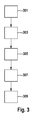
- a calculation is started (cf. Fig. 3 ).
- FIG. 3 For example, an exemplary flowchart of a method for operating a cornering light 109 is shown, with which the cornering light 109 can be controlled accordingly.
- the procedure is initiated by initiating a turn 301 started. This can be done by a certain steering angle at low speeds and / or turning on the turn signal at low speeds.
- the slope of the road being turned into, and possibly the slope of the road being driven on is obtained from the navigation unit.
- the maximum angle at which the cornering light 109 is allowed to radiate for example, is determined.
- parameters can be determined in a further step 307 with which the control of the cornering light 109 can be adjusted accordingly in order to regulate the cornering light 109 in accordance with the specifications.
- the cornering light 109 can be turned on.
- FIG. 4 is a traffic situation at an intersection darg Hort top drawing: top view, bottom drawing: view from the side, in which the road 103 from the perspective of the vehicle 101 rises steeply with a slope B3.
- the road 105 in which the vehicle is to turn left, in this example, for simplicity, no slope B4 have Thus, no reference number "B4" in the FIG. 4 located.
- the illumination area 107 for a cornering light 109 which does not take account of a gradient, is shown schematically in the figure up to the limit to which a road user could be blinded if he were to look directly into the cornering light 109.
- the vehicle Due to the slope of the road 103, the vehicle is also at a nearly similar angle to the road to be inflected, so that the light in the area of right side of the road, marked C1, the road 105 will appear higher, and in the area of the left-hand side of the road, marked C2, road 105 will reach a lower altitude.
- road users who are in the area of the right-hand roadside of the road 105 can be blinded by the turning light 109 in this case.
- the slope of the road 103 can be obtained from the navigation unit.
- the slope of the road 103 can also be estimated by means of the (longitudinal) inclination of the vehicle.
- One way of determining the inclination of the vehicle is inclination sensors, for example inclination sensors of a transmission, and / or pitch angle sensors.
- the height H1 of the illumination of the cornering light 109 can be determined. If the altitude exceeds a certain value, for example a predefined value, which ensures that the cornering light 109 does not dazzle any other road users, the cornering light can be adapted accordingly. Thus, the maximum angle at which the cornering light 109 may radiate upward, set or reduced. With the new setting, in this example, the illumination area 111 of the cornering light is then modified such that it does not exceed the height H4. Another possibility is, in this case, to restrict the cornering light 109 at the front more in the upward spread than the part of the cornering light 109 which seems to be rearward. This can be effected, for example, by selective switching on and off of light sources, for example light-emitting diodes (LED) lights, of the cornering light 109.
- LED light-emitting diodes
- the two cases described above are taken into account in combination, ie both the slope of the road 105 to be inflected and the slope of the road 103 on which the driver is currently driving are taken into account in the control of the cornering light 109.
- the inclination of the vehicle with respect to the flat road can be determined with the slope of the road 103 that can be obtained from the navigation unit.
- inclination sensors for example inclination sensors of a Transmission, and / or pitch angle sensors.
- the inclination of the vehicle as parameter is taken into account or used.
- the inclination of the vehicle as a parameter in addition to the slope of the road is taken into account or used.
- the following may additionally be considered: inclination of the vehicle in the longitudinal direction, for example due to loading and / or bank and / or longitudinal inclination of the vehicle.
- the road width of that road is taken into account, on which the vehicle is driving straight or momentarily.
- the width of the road on which the vehicle is currently traveling can be taken into account. This area has an influence on the maximum height that the illumination area 107 of the cornering light 109 can reach in the road sloping, for example.
- the area of the road across the vehicle is flat, that is, the bank of the road can be neglected.
- the road to be inflected then starts at the roadside where the vehicle is to fall off or climb. If the proportion of the own road which is illuminated by the turning light 109 is taken into account in the calculation, the distance at which the predefined height value of a falling road is reached by the light cone can be determined more accurately.
- the lane width can be determined by different methods. On the one hand, the lane width and possibly the number of lanes in each direction can be obtained from the navigation unit. If the lane width is not included in the map data of the navigation unit, information about the road class can generally be obtained. From the Road class can be indirectly estimated the road width, as road classes usually have a standard roadway width.
- the bank of the road on which the vehicle is currently traveling and / or the bank of the road to be inflected, be determined and used for the dependence of the control of the light characteristic.
- the road slope across the road can be stored in a navigation system.
- the bank of the road can also be measured with inclination sensors, which are aligned transversely to the direction of travel.
- the headlight of the cornering light can be adjusted without taking into account the gradients.
- Whether other road users are in this area can, for example, be detected by appropriate camera systems and recognized with image processing systems.
- various road users can communicate with one another, for example by communication techniques such as Car2Car or Car2X, and tell whether one of the road users is in the area of the cornering light 109.
- cyclists and / or pedestrians can be equipped with appropriate communication systems, so that information about their position in the crossing area can be taken into account in the control of the cornering light.
- the invention can also on the side strips and any wheel and / or footpaths at the edge of the road to be inflected, be extended. Glare of road users can thus be avoided in these areas in an advantageous manner.
- the steps according to the invention are initiated, ie the method according to the invention is started, if the cornering light 109 is to be switched on in intersections or after setting the turn signal or steering wheel turns at low speeds.
- the edge area of the road being driven is checked on a rising or falling edge area, wherein, preferably at any time, the illumination width and height are calculated to the cornering light 109th If necessary, to be able to adjust accordingly.
- the setting of the headlights of the cornering light also called turn-off headlights, be made immediately as soon as the cornering light is to be turned on the vehicle.
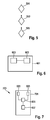
- FIG. 5 shows a flowchart of another method for operating a turning light of a vehicle.
- a step 501 at least one environmental parameter describing a property of an environment of a vehicle is determined.
- a step 503 a luminous characteristic of the cornering light is controlled based on the determined environmental parameter to adjust a light cone that can be generated by means of this cornering light according to a step 505.
- at least one parameter may be used as described in the present specification.
- FIG. 6 shows a vehicle lighting 601 for a vehicle (not shown).
- the vehicle lighting 601 includes a cornering light 603 and a controller 605.
- the controller is configured to emit a luminous characteristic of the cornering light in response to at least one of a characteristic of FIG To control environment surrounding the vehicle descriptive environmental parameters to set a producible by means of the cornering light cone can.
- FIG. 7 shows a vehicle 701 including a vehicle lighting 703.
- the vehicle lighting 703 includes two cornering lights 603 and 605 respectively disposed in a front side area (left and right) of the vehicle 701 and configured to radiate light away from the vehicle into the vehicle surroundings when activated to illuminate a side area.
- a controller 605 for controlling the two cornering lights 603 is provided as a function of at least one environmental parameter describing a property of an environment of the vehicle 701 in order to be able to set a light cone that can be generated by means of the cornering light.
- a parameter determination device 607 is provided, which is designed to determine an environmental parameter describing the environment of the vehicle.
Landscapes
- Engineering & Computer Science (AREA)
- Mechanical Engineering (AREA)
- Lighting Device Outwards From Vehicle And Optical Signal (AREA)
Applications Claiming Priority (1)
| Application Number | Priority Date | Filing Date | Title |
|---|---|---|---|
| DE102014206327.2A DE102014206327A1 (de) | 2014-04-02 | 2014-04-02 | Verfahren zum Betreiben eines Abbiegelichts eines Fahrzeugs und Fahrzeugbeleuchtung |
Publications (3)
| Publication Number | Publication Date |
|---|---|
| EP2927052A2 true EP2927052A2 (fr) | 2015-10-07 |
| EP2927052A3 EP2927052A3 (fr) | 2016-04-20 |
| EP2927052B1 EP2927052B1 (fr) | 2021-03-03 |
Family
ID=52633132
Family Applications (1)
| Application Number | Title | Priority Date | Filing Date |
|---|---|---|---|
| EP15158177.4A Active EP2927052B1 (fr) | 2014-04-02 | 2015-03-09 | Procédé de fonctionnement d'un feu de virage d'un véhicule et éclairage de véhicule |
Country Status (2)
| Country | Link |
|---|---|
| EP (1) | EP2927052B1 (fr) |
| DE (1) | DE102014206327A1 (fr) |
Cited By (1)
| Publication number | Priority date | Publication date | Assignee | Title |
|---|---|---|---|---|
| CN110979157A (zh) * | 2019-12-09 | 2020-04-10 | 北京海纳川汽车部件股份有限公司 | 车辆照明控制系统和车辆 |
Citations (1)
| Publication number | Priority date | Publication date | Assignee | Title |
|---|---|---|---|---|
| US5769524A (en) | 1996-12-12 | 1998-06-23 | Yuan; Zhiping | Vehicle lighting systems with side lights |
Family Cites Families (10)
| Publication number | Priority date | Publication date | Assignee | Title |
|---|---|---|---|---|
| US20030137849A1 (en) * | 2002-01-22 | 2003-07-24 | Alden Ray M. | Segmented distribution headlight system, method, and apparatus |
| JP4392786B2 (ja) * | 2003-11-04 | 2010-01-06 | 株式会社小糸製作所 | 車両用前照灯 |
| DE102007038077A1 (de) * | 2007-08-11 | 2009-02-12 | Daimler Ag | Verfahren und Vorrichtung zur Fahrlichtsteuerung eines Fahrzeugs |
| DE102007041703A1 (de) * | 2007-09-03 | 2009-03-05 | GM Global Technology Operations, Inc., Detroit | Kraftfahrzeug mit einem Navigationssystem und einem AFL-Scheinwerfersystem |
| DE102008014182A1 (de) * | 2008-03-14 | 2009-09-17 | Daimler Ag | Verfahren zur Fahrlichtsteuerung eines Fahrzeugs |
| DE102009022637B4 (de) * | 2009-05-26 | 2018-11-15 | Volkswagen Ag | Verfahren und Vorrichtung zur Ansteuerung der Beleuchtungseinrichtung eines Kraftfahrzeugs |
| US20110205049A1 (en) * | 2010-02-22 | 2011-08-25 | Koninklijke Philips Electronics N.V. | Adaptive lighting system with iii-nitride light emitting devices |
| DE102011105983A1 (de) * | 2011-06-29 | 2013-01-03 | SMR Patents S.à.r.l. | Nahbereich-Kurvenlicht im Außenspiegel |
| DE102011055794B4 (de) * | 2011-11-29 | 2014-09-04 | Varroc Lighting Systems S.R.O | Verfahren zur Steuerung von Kraftfahrzeugscheinwerfern und Anordnung zur Durchführung des Verfahrens |
| DE102012200431B4 (de) * | 2012-01-12 | 2019-08-08 | Robert Bosch Gmbh | Verfahren zur Bestimmung eines Vorliegens einer Kreuzung in einem von einem Fahrzeug befahrenen Straßenverlauf |
-
2014
- 2014-04-02 DE DE102014206327.2A patent/DE102014206327A1/de not_active Withdrawn
-
2015
- 2015-03-09 EP EP15158177.4A patent/EP2927052B1/fr active Active
Patent Citations (1)
| Publication number | Priority date | Publication date | Assignee | Title |
|---|---|---|---|---|
| US5769524A (en) | 1996-12-12 | 1998-06-23 | Yuan; Zhiping | Vehicle lighting systems with side lights |
Cited By (1)
| Publication number | Priority date | Publication date | Assignee | Title |
|---|---|---|---|---|
| CN110979157A (zh) * | 2019-12-09 | 2020-04-10 | 北京海纳川汽车部件股份有限公司 | 车辆照明控制系统和车辆 |
Also Published As
| Publication number | Publication date |
|---|---|
| EP2927052A3 (fr) | 2016-04-20 |
| DE102014206327A1 (de) | 2015-10-08 |
| EP2927052B1 (fr) | 2021-03-03 |
Similar Documents
| Publication | Publication Date | Title |
|---|---|---|
| EP2562039B1 (fr) | Procédé et dispositif destinés à modifier une émission lumineuse, notamment d'un phare d'un véhicule | |
| DE102013020754B4 (de) | Verfahren zum Betreiben eines Scheinwerfers für ein Kraftfahrzeug | |
| EP3402694B1 (fr) | Système de phare et procédé de fourniture d'une fonction d'éclairage de virage | |
| EP2691264B1 (fr) | Procédé et appareil de commande permettant de régler la portée des phares d'un système d'éclairage d'un véhicule en fonction de la distance | |
| EP3430307B1 (fr) | Véhicule à moteur pourvu d'au moins un projecteur | |
| DE102014226254A1 (de) | Verfahren zum Betreiben eines insbesondere autonom oder teilautonom fahrenden/fahrbaren Kraftfahrzeugs, Signalisierungsvorrichtung, Kraftfahrzeug | |
| EP2691263B1 (fr) | Procédé et appareil de commande pour éclairer les feux de route d'un véhicule | |
| DE102018206087B4 (de) | Verfahren zur Kommunikation eines Kraftfahrzeugs mit einem Verkehrsteilnehmer sowie Kraftfahrzeug zur Durchführung des Verfahrens | |
| DE112015000723T5 (de) | Scheinwerfersteuervorrichtung | |
| DE102017117242A1 (de) | Fahrzeugbeleuchtungsvorrichtung | |
| DE102012200431B4 (de) | Verfahren zur Bestimmung eines Vorliegens einer Kreuzung in einem von einem Fahrzeug befahrenen Straßenverlauf | |
| EP2562044B1 (fr) | Procédé de régulation de l'émission lumineuse d'un phare de véhicule | |
| DE102015011231B4 (de) | Verfahren zum Betrieb einer in einem Kraftfahrzeug angeordneten Laserheckleuchte, Laserheckleuchte und Kraftfahrzeug | |
| DE102016220054A1 (de) | Verfahren zum Betreiben von Anzeigeeinrichtungen von Kraftfahrzeugen einer Kraftfahrzeugkolonne und System mit einer Kraftfahrzeugkolonne | |
| EP3781439A1 (fr) | Procédé permettant la communication d'un véhicule à moteur avec un usager de la route et véhicule à moteur pour mettre en oeuvre ledit procédé | |
| DE102012016782A1 (de) | Verfahren zum Betreiben eines Scheinwerfersystems und Scheinwerfersystem für ein Fahrzeug | |
| EP3592604A1 (fr) | Véhicule automobile comprenant un module d'éclairage servant à générer un symbole | |
| EP3548337B1 (fr) | Commande d'un phare de véhicule automobile | |
| DE102014221883A1 (de) | Verfahren und Steuergerät zum Einstellen einer Charakteristik einer Lichtaussendung zumindest eines Scheinwerfers eines Fahrzeugs | |
| EP2927052B1 (fr) | Procédé de fonctionnement d'un feu de virage d'un véhicule et éclairage de véhicule | |
| WO2018019413A1 (fr) | Dispositif de commande pour un phare et procédé permettant de faire fonctionner un phare | |
| EP3548335B1 (fr) | Commande d'un feu avant commandable d'un véhicule automobile | |
| DE102015207938A1 (de) | Verfahren zur Steuerung einer Leuchtintensität von Bremslichtern | |
| DE102013001286A1 (de) | Scheinwerfersystem für ein Kraftfahrzeug | |
| DE102022130176A1 (de) | Steuervorrichtung zum steuern eines scheinwerferlichts, fahrzeug und verfahren |
Legal Events
| Date | Code | Title | Description |
|---|---|---|---|
| PUAI | Public reference made under article 153(3) epc to a published international application that has entered the european phase |
Free format text: ORIGINAL CODE: 0009012 |
|
| AK | Designated contracting states |
Kind code of ref document: A2 Designated state(s): AL AT BE BG CH CY CZ DE DK EE ES FI FR GB GR HR HU IE IS IT LI LT LU LV MC MK MT NL NO PL PT RO RS SE SI SK SM TR |
|
| AX | Request for extension of the european patent |
Extension state: BA ME |
|
| PUAL | Search report despatched |
Free format text: ORIGINAL CODE: 0009013 |
|
| AK | Designated contracting states |
Kind code of ref document: A3 Designated state(s): AL AT BE BG CH CY CZ DE DK EE ES FI FR GB GR HR HU IE IS IT LI LT LU LV MC MK MT NL NO PL PT RO RS SE SI SK SM TR |
|
| AX | Request for extension of the european patent |
Extension state: BA ME |
|
| RIC1 | Information provided on ipc code assigned before grant |
Ipc: B60Q 1/14 20060101AFI20160314BHEP Ipc: B60Q 1/18 20060101ALI20160314BHEP |
|
| 17P | Request for examination filed |
Effective date: 20161020 |
|
| RBV | Designated contracting states (corrected) |
Designated state(s): AL AT BE BG CH CY CZ DE DK EE ES FI FR GB GR HR HU IE IS IT LI LT LU LV MC MK MT NL NO PL PT RO RS SE SI SK SM TR |
|
| STAA | Information on the status of an ep patent application or granted ep patent |
Free format text: STATUS: EXAMINATION IS IN PROGRESS |
|
| 17Q | First examination report despatched |
Effective date: 20191014 |
|
| RAP1 | Party data changed (applicant data changed or rights of an application transferred) |
Owner name: ROBERT BOSCH GMBH |
|
| GRAP | Despatch of communication of intention to grant a patent |
Free format text: ORIGINAL CODE: EPIDOSNIGR1 |
|
| STAA | Information on the status of an ep patent application or granted ep patent |
Free format text: STATUS: GRANT OF PATENT IS INTENDED |
|
| INTG | Intention to grant announced |
Effective date: 20201001 |
|
| GRAS | Grant fee paid |
Free format text: ORIGINAL CODE: EPIDOSNIGR3 |
|
| STAA | Information on the status of an ep patent application or granted ep patent |
Free format text: STATUS: GRANT OF PATENT IS INTENDED |
|
| GRAA | (expected) grant |
Free format text: ORIGINAL CODE: 0009210 |
|
| STAA | Information on the status of an ep patent application or granted ep patent |
Free format text: STATUS: THE PATENT HAS BEEN GRANTED |
|
| AK | Designated contracting states |
Kind code of ref document: B1 Designated state(s): AL AT BE BG CH CY CZ DE DK EE ES FI FR GB GR HR HU IE IS IT LI LT LU LV MC MK MT NL NO PL PT RO RS SE SI SK SM TR |
|
| REG | Reference to a national code |
Ref country code: GB Ref legal event code: FG4D Free format text: NOT ENGLISH |
|
| REG | Reference to a national code |
Ref country code: AT Ref legal event code: REF Ref document number: 1366860 Country of ref document: AT Kind code of ref document: T Effective date: 20210315 Ref country code: CH Ref legal event code: EP |
|
| REG | Reference to a national code |
Ref country code: DE Ref legal event code: R096 Ref document number: 502015014327 Country of ref document: DE |
|
| REG | Reference to a national code |
Ref country code: IE Ref legal event code: FG4D Free format text: LANGUAGE OF EP DOCUMENT: GERMAN |
|
| REG | Reference to a national code |
Ref country code: LT Ref legal event code: MG9D |
|
| PG25 | Lapsed in a contracting state [announced via postgrant information from national office to epo] |
Ref country code: LT Free format text: LAPSE BECAUSE OF FAILURE TO SUBMIT A TRANSLATION OF THE DESCRIPTION OR TO PAY THE FEE WITHIN THE PRESCRIBED TIME-LIMIT Effective date: 20210303 Ref country code: GR Free format text: LAPSE BECAUSE OF FAILURE TO SUBMIT A TRANSLATION OF THE DESCRIPTION OR TO PAY THE FEE WITHIN THE PRESCRIBED TIME-LIMIT Effective date: 20210604 Ref country code: FI Free format text: LAPSE BECAUSE OF FAILURE TO SUBMIT A TRANSLATION OF THE DESCRIPTION OR TO PAY THE FEE WITHIN THE PRESCRIBED TIME-LIMIT Effective date: 20210303 Ref country code: HR Free format text: LAPSE BECAUSE OF FAILURE TO SUBMIT A TRANSLATION OF THE DESCRIPTION OR TO PAY THE FEE WITHIN THE PRESCRIBED TIME-LIMIT Effective date: 20210303 Ref country code: BG Free format text: LAPSE BECAUSE OF FAILURE TO SUBMIT A TRANSLATION OF THE DESCRIPTION OR TO PAY THE FEE WITHIN THE PRESCRIBED TIME-LIMIT Effective date: 20210603 Ref country code: NO Free format text: LAPSE BECAUSE OF FAILURE TO SUBMIT A TRANSLATION OF THE DESCRIPTION OR TO PAY THE FEE WITHIN THE PRESCRIBED TIME-LIMIT Effective date: 20210603 |
|
| REG | Reference to a national code |
Ref country code: NL Ref legal event code: MP Effective date: 20210303 |
|
| PG25 | Lapsed in a contracting state [announced via postgrant information from national office to epo] |
Ref country code: SE Free format text: LAPSE BECAUSE OF FAILURE TO SUBMIT A TRANSLATION OF THE DESCRIPTION OR TO PAY THE FEE WITHIN THE PRESCRIBED TIME-LIMIT Effective date: 20210303 Ref country code: LV Free format text: LAPSE BECAUSE OF FAILURE TO SUBMIT A TRANSLATION OF THE DESCRIPTION OR TO PAY THE FEE WITHIN THE PRESCRIBED TIME-LIMIT Effective date: 20210303 Ref country code: PL Free format text: LAPSE BECAUSE OF FAILURE TO SUBMIT A TRANSLATION OF THE DESCRIPTION OR TO PAY THE FEE WITHIN THE PRESCRIBED TIME-LIMIT Effective date: 20210303 Ref country code: RS Free format text: LAPSE BECAUSE OF FAILURE TO SUBMIT A TRANSLATION OF THE DESCRIPTION OR TO PAY THE FEE WITHIN THE PRESCRIBED TIME-LIMIT Effective date: 20210303 |
|
| PG25 | Lapsed in a contracting state [announced via postgrant information from national office to epo] |
Ref country code: NL Free format text: LAPSE BECAUSE OF FAILURE TO SUBMIT A TRANSLATION OF THE DESCRIPTION OR TO PAY THE FEE WITHIN THE PRESCRIBED TIME-LIMIT Effective date: 20210303 |
|
| PG25 | Lapsed in a contracting state [announced via postgrant information from national office to epo] |
Ref country code: EE Free format text: LAPSE BECAUSE OF FAILURE TO SUBMIT A TRANSLATION OF THE DESCRIPTION OR TO PAY THE FEE WITHIN THE PRESCRIBED TIME-LIMIT Effective date: 20210303 Ref country code: CZ Free format text: LAPSE BECAUSE OF FAILURE TO SUBMIT A TRANSLATION OF THE DESCRIPTION OR TO PAY THE FEE WITHIN THE PRESCRIBED TIME-LIMIT Effective date: 20210303 Ref country code: SM Free format text: LAPSE BECAUSE OF FAILURE TO SUBMIT A TRANSLATION OF THE DESCRIPTION OR TO PAY THE FEE WITHIN THE PRESCRIBED TIME-LIMIT Effective date: 20210303 |
|
| REG | Reference to a national code |
Ref country code: CH Ref legal event code: PL |
|
| PG25 | Lapsed in a contracting state [announced via postgrant information from national office to epo] |
Ref country code: IS Free format text: LAPSE BECAUSE OF FAILURE TO SUBMIT A TRANSLATION OF THE DESCRIPTION OR TO PAY THE FEE WITHIN THE PRESCRIBED TIME-LIMIT Effective date: 20210703 Ref country code: ES Free format text: LAPSE BECAUSE OF FAILURE TO SUBMIT A TRANSLATION OF THE DESCRIPTION OR TO PAY THE FEE WITHIN THE PRESCRIBED TIME-LIMIT Effective date: 20210303 Ref country code: PT Free format text: LAPSE BECAUSE OF FAILURE TO SUBMIT A TRANSLATION OF THE DESCRIPTION OR TO PAY THE FEE WITHIN THE PRESCRIBED TIME-LIMIT Effective date: 20210705 Ref country code: RO Free format text: LAPSE BECAUSE OF FAILURE TO SUBMIT A TRANSLATION OF THE DESCRIPTION OR TO PAY THE FEE WITHIN THE PRESCRIBED TIME-LIMIT Effective date: 20210303 Ref country code: SK Free format text: LAPSE BECAUSE OF FAILURE TO SUBMIT A TRANSLATION OF THE DESCRIPTION OR TO PAY THE FEE WITHIN THE PRESCRIBED TIME-LIMIT Effective date: 20210303 |
|
| REG | Reference to a national code |
Ref country code: DE Ref legal event code: R097 Ref document number: 502015014327 Country of ref document: DE |
|
| REG | Reference to a national code |
Ref country code: BE Ref legal event code: MM Effective date: 20210331 |
|
| PLBE | No opposition filed within time limit |
Free format text: ORIGINAL CODE: 0009261 |
|
| STAA | Information on the status of an ep patent application or granted ep patent |
Free format text: STATUS: NO OPPOSITION FILED WITHIN TIME LIMIT |
|
| PG25 | Lapsed in a contracting state [announced via postgrant information from national office to epo] |
Ref country code: IE Free format text: LAPSE BECAUSE OF NON-PAYMENT OF DUE FEES Effective date: 20210309 Ref country code: DK Free format text: LAPSE BECAUSE OF FAILURE TO SUBMIT A TRANSLATION OF THE DESCRIPTION OR TO PAY THE FEE WITHIN THE PRESCRIBED TIME-LIMIT Effective date: 20210303 Ref country code: AL Free format text: LAPSE BECAUSE OF FAILURE TO SUBMIT A TRANSLATION OF THE DESCRIPTION OR TO PAY THE FEE WITHIN THE PRESCRIBED TIME-LIMIT Effective date: 20210303 Ref country code: CH Free format text: LAPSE BECAUSE OF NON-PAYMENT OF DUE FEES Effective date: 20210331 Ref country code: MC Free format text: LAPSE BECAUSE OF FAILURE TO SUBMIT A TRANSLATION OF THE DESCRIPTION OR TO PAY THE FEE WITHIN THE PRESCRIBED TIME-LIMIT Effective date: 20210303 Ref country code: LI Free format text: LAPSE BECAUSE OF NON-PAYMENT OF DUE FEES Effective date: 20210331 Ref country code: LU Free format text: LAPSE BECAUSE OF NON-PAYMENT OF DUE FEES Effective date: 20210309 |
|
| 26N | No opposition filed |
Effective date: 20211206 |
|
| GBPC | Gb: european patent ceased through non-payment of renewal fee |
Effective date: 20210603 |
|
| PG25 | Lapsed in a contracting state [announced via postgrant information from national office to epo] |
Ref country code: SI Free format text: LAPSE BECAUSE OF FAILURE TO SUBMIT A TRANSLATION OF THE DESCRIPTION OR TO PAY THE FEE WITHIN THE PRESCRIBED TIME-LIMIT Effective date: 20210303 |
|
| PG25 | Lapsed in a contracting state [announced via postgrant information from national office to epo] |
Ref country code: IT Free format text: LAPSE BECAUSE OF FAILURE TO SUBMIT A TRANSLATION OF THE DESCRIPTION OR TO PAY THE FEE WITHIN THE PRESCRIBED TIME-LIMIT Effective date: 20210303 Ref country code: GB Free format text: LAPSE BECAUSE OF NON-PAYMENT OF DUE FEES Effective date: 20210603 |
|
| REG | Reference to a national code |
Ref country code: AT Ref legal event code: MM01 Ref document number: 1366860 Country of ref document: AT Kind code of ref document: T Effective date: 20210309 |
|
| PG25 | Lapsed in a contracting state [announced via postgrant information from national office to epo] |
Ref country code: IS Free format text: LAPSE BECAUSE OF FAILURE TO SUBMIT A TRANSLATION OF THE DESCRIPTION OR TO PAY THE FEE WITHIN THE PRESCRIBED TIME-LIMIT Effective date: 20210703 |
|
| PG25 | Lapsed in a contracting state [announced via postgrant information from national office to epo] |
Ref country code: BE Free format text: LAPSE BECAUSE OF NON-PAYMENT OF DUE FEES Effective date: 20210331 |
|
| PG25 | Lapsed in a contracting state [announced via postgrant information from national office to epo] |
Ref country code: AT Free format text: LAPSE BECAUSE OF NON-PAYMENT OF DUE FEES Effective date: 20210309 |
|
| PGFP | Annual fee paid to national office [announced via postgrant information from national office to epo] |
Ref country code: FR Payment date: 20230320 Year of fee payment: 9 |
|
| PG25 | Lapsed in a contracting state [announced via postgrant information from national office to epo] |
Ref country code: HU Free format text: LAPSE BECAUSE OF FAILURE TO SUBMIT A TRANSLATION OF THE DESCRIPTION OR TO PAY THE FEE WITHIN THE PRESCRIBED TIME-LIMIT; INVALID AB INITIO Effective date: 20150309 |
|
| PG25 | Lapsed in a contracting state [announced via postgrant information from national office to epo] |
Ref country code: CY Free format text: LAPSE BECAUSE OF FAILURE TO SUBMIT A TRANSLATION OF THE DESCRIPTION OR TO PAY THE FEE WITHIN THE PRESCRIBED TIME-LIMIT Effective date: 20210303 |
|
| PGFP | Annual fee paid to national office [announced via postgrant information from national office to epo] |
Ref country code: DE Payment date: 20230524 Year of fee payment: 9 |
|
| PG25 | Lapsed in a contracting state [announced via postgrant information from national office to epo] |
Ref country code: MK Free format text: LAPSE BECAUSE OF FAILURE TO SUBMIT A TRANSLATION OF THE DESCRIPTION OR TO PAY THE FEE WITHIN THE PRESCRIBED TIME-LIMIT Effective date: 20210303 |