EP2927019B1 - Rollvorrichtung mit Stufensteigfunktion - Google Patents
Rollvorrichtung mit Stufensteigfunktion Download PDFInfo
- Publication number
- EP2927019B1 EP2927019B1 EP14162732.3A EP14162732A EP2927019B1 EP 2927019 B1 EP2927019 B1 EP 2927019B1 EP 14162732 A EP14162732 A EP 14162732A EP 2927019 B1 EP2927019 B1 EP 2927019B1
- Authority
- EP
- European Patent Office
- Prior art keywords
- rolling
- rolling members
- radius
- members
- positioning mechanism
- Prior art date
- Legal status (The legal status is an assumption and is not a legal conclusion. Google has not performed a legal analysis and makes no representation as to the accuracy of the status listed.)
- Active
Links
Images


Classifications
-
- A—HUMAN NECESSITIES
- A45—HAND OR TRAVELLING ARTICLES
- A45C—PURSES; LUGGAGE; HAND CARRIED BAGS
- A45C5/00—Rigid or semi-rigid luggage
- A45C5/14—Rigid or semi-rigid luggage with built-in rolling means
-
- A—HUMAN NECESSITIES
- A45—HAND OR TRAVELLING ARTICLES
- A45C—PURSES; LUGGAGE; HAND CARRIED BAGS
- A45C5/00—Rigid or semi-rigid luggage
- A45C5/14—Rigid or semi-rigid luggage with built-in rolling means
- A45C2005/147—Rigid or semi-rigid luggage with built-in rolling means for climbing stairs
Definitions
- a step-climbing wheel is known from US 2011/0127732 A1 .
- a wheel or castor is a rolling device, has a circular outline, and is typically rotatable about a rotating axis. When the wheel is mounted to an article to be moved, and when the article is pushed or pulled, the wheel can roll on the ground surface. For example, when a plurality of castors are mounted to a luggage case, the luggage case can be moved conveniently in a labor-saving manner.
- the object of this invention is to provide a rolling device having step-climbing function.
- a rolling device includes an axle rotatable about an axis, a plurality of first rolling members, and a plurality of second rolling members.
- the first rolling members are connected fixedly to the axle.
- Each of the first rolling members includes a first body having a first rolling surface that is contactable with the ground surface and that is spaced apart from the axis by a first radius. Any two adjacent ones of the first rolling members define an accommodating space therebetween.
- Each of the second rolling members is disposed movably within the accommodating space between two adjacent ones of the first rolling members.
- Each of the second rolling members includes a second body having a second rolling surface that is contactable with the ground surface and that is spaced apart from the axis by a second radius.
- Each of the second rolling members is movable relative to the first rolling members between a retracted position whereat the second radius is not more than the first radius, and an extended position whereat the second radius is more than the first radius.
- the rolling device further includes a plurality of reinforcing units each connected between two adjacent ones of the first rolling members.
- Each of the reinforcing units includes two reinforcing walls connected respectively to two opposite sides of each of two adjacent ones of the first rolling members.
- Each of the second rolling members further includes a first positioning mechanism disposed at the second body.
- Each of the reinforcing units further includes a second positioning mechanism disposed on the two reinforcing walls and cooperating with the first positioning mechanism of a corresponding one of the second rolling members to maintain a corresponding one of the second rolling members at a selected one of the retracted position and the extended position.
- the first positioning mechanism of each of the second rolling members includes a plurality of positioning holes formed through the second body of a corresponding one of the second rolling members
- the second positioning mechanism of each of the reinforcing units includes a plurality of positioning pins each extending through a corresponding one of the positioning holes and two corresponding ones of the reinforcing walls.
- a rolling device includes an axle rotatable about an axis, a plurality of first rolling members, and a plurality of second rolling members.
- the first rolling members are connected fixedly to the axle.
- Each of the first rolling members includes a first body having a first rolling surface that is contactable with the ground surface and that is spaced apart from the axis by a first radius. Any two adjacent ones of the first rolling members define an accommodating space therebetween.
- Each of the second rolling members is disposed movably within the accommodating space between two adjacent ones of the first rolling members.
- Each of the second rolling members includes a second body having a second rolling surface that is contactable with the ground surface and that is spaced apart from the axis by a second radius.
- Each of the second rolling members is movable relative to the first rolling members between a retracted position whereat the second radius is not more than the first radius, and an extended position whereat the second radius is more than the first radius.
- the rolling device further includes a plurality of reinforcing units each connected between two adjacent ones of the first rolling members.
- Each of the reinforcing units includes two reinforcing walls connected respectively to two opposite sides of each of two adjacent ones of the first rolling members.
- Each of the second rolling members further includes a first positioning mechanism disposed at the second body.
- Each of the reinforcing units further includes a second positioning mechanism disposed on the two reinforcing walls and cooperating with the first positioning mechanism of a corresponding one of the second rolling members to maintain a corresponding one of the second rolling members at a selected one of the retracted position and the extended position.
- the first positioning mechanism of each of the second rolling members includes a plurality of threaded holes formed therethrough the second body of a corresponding one of the second rolling members
- the second positioning mechanism of each of the reinforcing units includes a plurality of positioning bolts each extending through a corresponding one of the threaded holes and two corresponding ones of the reinforcing walls.
- the rolling device in a situation where the rolling device is used on a stepped surface that has a first horizontal surface portion, a second horizontal surface portion higher than the first horizontal surface portion, and a connecting surface portion connected between the first and second horizontal surface portions, when each of the second rolling members is disposed at the extended position, and when the rolling device is rolled on the first horizontal surface portion toward the connecting surface portion, one of the second rolling members may come into contact with the second horizontal surface portion to allow the rolling device to roll onto the second horizontal surface portion.
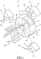
- the first preferred embodiment of a rolling device 1 includes an axle 2 rotatable about an axis (C), a plurality of first rolling members 3 connected fixedly to the axle 2 and angularly spaced apart from each other such that any two adjacent ones of the first rolling members 3 define an accommodating space 4 therebetween, a plurality of second rolling members 5 each disposed movably within the accommodating space 4 between two adjacent first rolling members 3, and a plurality of reinforcing units 6 each connected between two adjacent first rolling members 3.
- the first rolling members 3 cooperate with the second rolling members 5 to constitute a wheel body disposed around the axle 2.
- the number of the first rolling members 3 is three. That is, the rolling device 1 includes three accommodating spaces 4, three second rolling members 5, and three reinforcing units 6.
- Each first rolling member 3 includes a first body 30 having a first rolling surface 31 that is contactable with the ground surface.
- Each second rolling member 5 Includes a second body 50 having a second rolling surface 51 that is contactable with the ground surface, and a first positioning mechanism 52 disposed at the second body 50.
- Each second rolling member 5 is movable relative to the first rolling members 3 between a retracted position shown in Fig. 2 and an extended position shown in Fig. 3 .
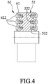
- each reinforcing unit 6 includes two reinforcing walls 61 connected respectively to two opposite sides of each of the two adjacent first rolling members 3, and a second positioning mechanism 62 disposed on the two reinforcing walls 61.
- each second positioning mechanism 62 cooperates with the first positioning mechanism 52 of the corresponding second rolling member 5 to maintain the corresponding second rolling member 5 at a selected one of the retracted position and the extended position.
- each first positioning mechanism 52 includes a plurality of positioning holes 521 formed through the corresponding second body 50
- each second positioning mechanism 62 includes a plurality of positioning pins 621 each extending through the corresponding positioning hole 521 and two corresponding reinforcing walls 61.
- each first positioning mechanism 52 may include a plurality of threaded holes 522 formed through the second body 50 of the corresponding second rolling member 5, and each second positioning mechanism 62 may include a plurality of positioning bolts 622 each extending through the corresponding threaded hole 522 and two corresponding reinforcing walls 61.
- each first rolling surface 31 is spaced apart from the axis (C) by a first radius L1
- each second rolling surface 51 is spaced apart from the axis (C) by a second radius L2.
- first and second rolling surfaces 31, 51 cooperate to allow the rolling device 1 to roll smoothly on a flat surface (A).
- the reinforcing walls 61 can promote the structural strength of the rolling device 1.
- each second rolling member 5 when moved on a stepped surface 7, each second rolling member 5 is disposed at the extended position, and projects partially from the corresponding accommodating space 4, so that the second radius L2 is more than the first radius L1.
- the stepped surface 7 has a first horizontal surface portion 71, a second horizontal surface portion 72 higher than the first horizontal surface portion 71, and a connecting surface portion 73 connected between the first and second horizontal surface portions 71, 72.
- the rolling device 1 is rolled on the first horizontal surface portion 71 toward the connecting surface portion 73, one of the second rolling members 5 may come into contact with the second horizontal surface portion 72 to allow the rolling device 1 to roll onto the second horizontal surface portion 72.
- the step-climbing function of the rolling device 1 can be affected by the height and inclination angle of the connecting surface portion 73.
- the rolling device 1 is suitable for use on a luggage case (not shown).
- each second rolling member 5 is disposed at the retracted position.
- each second rolling member 5 is disposed at the extended position.
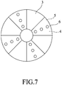
- the number of the first rolling members 3 may be changed according to different needs.
- the number of the first rolling members 3 may be increased to four, as shown in Fig. 7 .
- the number of the accommodating spaces 4, the second rolling members 5, and the reinforcing units 6 must be changed correspondingly.
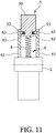
- Figs. 8 and 9 show a second preferred embodiment of a rolling device not to the invention.
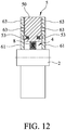
- the rolling device 1 further includes a plurality of resilient members 8 each disposed between the axle 2 and a respective one of the second rolling members 5, each second rolling members 5 further includes two spring-biased balls or pushbuttons 53 that are extendable from and retractable into the second body 50, and each reinforcing wall 61 is formed with a plurality of positioning holes 63.
- each resilient member 8 when no external force is applied, each resilient member 8 is in a fully stretched state, so that each spring-biased pushbutton 53 is disposed outwardly of the corresponding accommodating space 4 and is biased to project partially from the corresponding second body 50.
- the two spring-biased pushbuttons 53 can be pressed to allow the corresponding second rolling member 5 to be moved toward the axle (2) such that the two spring-biased pushbuttons 53 are in slidable contact with the corresponding reinforcing walls 61, as shown in Fig. 10 .
- the corresponding second rolling member 5 can be released to maintain the corresponding second rolling member 5 at a first position relative to the axle 2.
- the two spring-biased pushbuttons 53 may move to align respectively with another two of the positioning holes 63.
- the corresponding second rolling member 5 is released, it can be maintained at a second position.
- the positions of the second rolling members 5 can be adjusted easily without removal of the second positioning mechanisms 62 (see Fig. 1 ), so as to increase convenience during position adjustment. If desired, the number of the positioning holes 63 in each reinforcing wall 61 can be changed.
- the rolling device 1 has step-climbing function.
Landscapes
- Handcart (AREA)
Claims (4)
- Eine Rollvorrichtung (1), die eine Achswelle (2), die um eine Achse (C) drehbar ist, und einen Radkörper umfasst, der um die Achswelle (2) angeordnet ist, wobei der Radkörper folgende Merkmale umfasst:eine Mehrzahl von ersten Rollbaugliedern (3), die fest mit der Achswelle (2) verbunden sind und winklig voneinander beabstandet sind, wobei jedes der ersten Rollbauglieder (3) einen ersten Körper (30) mit einer ersten Rolloberfläche (31) umfasst, die mit der Bodenoberfläche kontaktierbar ist und die von der Achse (C) um einen ersten Radius (L1) beabstandet ist, wobei jeweils zwei benachbarte der ersten Rollbauglieder (3) einen Aufnahmeraum (4) zwischen sich definieren; undeine Mehrzahl von zweiten Rollbaugliedern (5), die jeweils bewegbar in dem Aufnahmeraum (4) zwischen zwei benachbarten der ersten Rollbauglieder (3) angeordnet sind, wobei jedes der zweiten Rollbauglieder (5) einen zweiten Körper (50) mit einer zweiten Rolloberfläche (51) umfasst, die mit der Bodenoberfläche kontaktierbar ist und die von der Achse (C) um einen zweiten Radius (L2) beabstandet ist, wobei jedes der zweiten Rollbauglieder (5) relativ zu den ersten Rollbaugliedern (3) bewegbar ist zwischen einer zurückgezogenen Position, an der der zweite Radius (L2) nicht größer ist als der erste Radius (L1), und einer ausgefahrenen Position, an der der zweite Radius (L2) größer ist als der erste Radius (L1);wobei die Rollvorrichtung (1) ferner eine Mehrzahl von Verstärkungseinheiten (6) umfasst, die jeweils zwischen zwei benachbarten der ersten Rollbauglieder (3) verbunden sind;wobei jede der Verstärkungseinheiten (6) zwei Verstärkungswände (61) umfasst, die jeweils mit zwei gegenüberliegenden Seiten von jeweils zwei benachbarten der ersten Rollbauglieder (3) verbunden sind;wobei jedes der zweiten Rollbauglieder (5) ferner einen ersten Positionierungsmechanismus (52) umfasst, der an dem zweiten Körper (50) angeordnet ist, wobei jede der Verstärkungseinheiten (6) ferner einen zweiten Positionierungsmechanismus (62) umfasst, der an den zwei Verstärkungswänden (61) angeordnet ist und mit dem ersten Positionierungsmechanismus (52) eines entsprechenden der zweiten Rollbauglieder (5) zusammenwirkt, um ein entsprechendes der zweiten Rollbauglieder (5) an einer ausgewählten der zurückgezogenen Position und der ausgefahrenen Position zu halten; undwobei die Rollvorrichtung (1) dadurch gekennzeichnet ist, dass:der erste Positionierungsmechanismus (52) von jedem der zweiten Rollbauglieder (5) eine Mehrzahl von Positionierungslöchern (521) umfasst, die durch den zweiten Körper (50) eines entsprechenden der zweiten Rollbauglieder (5) gebildet sind, und der zweite Positionierungsmechanismus (62) von jeder der Verstärkungseinheiten (6) eine Mehrzahl von Positionierungsstiften (621) umfasst, die sich jeweils durch ein entsprechendes der Positionierungslöcher (521) und zwei entsprechende der Verstärkungswände (61) erstrecken.
- Die Rollvorrichtung (1) gemäß Anspruch 1, dadurch gekennzeichnet, dass die Anzahl der ersten Rollbauglieder (3) drei beträgt.
- Eine Rollvorrichtung (1), die eine Achswelle (2), die um eine Achse (C) drehbar ist, und einen Radkörper umfasst, der um die Achswelle (2) angeordnet ist, wobei der Radkörper folgende Merkmale umfasst:eine Mehrzahl von ersten Rollbaugliedern (3), die fest mit der Achswelle (2) verbunden sind und winklig voneinander beabstandet sind, wobei jedes der ersten Rollbauglieder (3) einen ersten Körper (30) mit einer ersten Rolloberfläche (31) umfasst, die mit der Bodenoberfläche kontaktierbar ist und die von der Achse (C) um einen ersten Radius (L1) beabstandet ist, wobei jeweils zwei benachbarte der ersten Rollbauglieder (3) einen Aufnahmeraum (4) zwischen sich definieren; undeine Mehrzahl von zweiten Rollbaugliedern (5), die jeweils bewegbar in dem Aufnahmeraum (4) zwischen zwei benachbarten der ersten Rollbauglieder (3) angeordnet sind, wobei jedes der zweiten Rollbauglieder (5) einen zweiten Körper (50) mit einer zweiten Rolloberfläche (51) umfasst, die mit der Bodenoberfläche kontaktierbar ist und die von der Achse (C) um einen zweiten Radius (L2) beabstandet ist, wobei jedes der zweiten Rollbauglieder (5) relativ zu den ersten Rollbaugliedern (3) bewegbar ist zwischen einer zurückgezogenen Position, an der der zweite Radius (L2) nicht größer ist als der erste Radius (L1), und einer ausgefahrenen Position, an der der zweite Radius (L2) größer ist als der erste Radius (L1);wobei die Rollvorrichtung (1) ferner eine Mehrzahl von Verstärkungseinheiten (6) umfasst, die jeweils zwischen zwei benachbarten der ersten Rollbauglieder (3) verbunden sind;wobei jede der Verstärkungseinheiten (6) zwei Verstärkungswände (61) umfasst, die jeweils mit zwei gegenüberliegenden Seiten von jeweils zwei benachbarten der ersten Rollbauglieder (3) verbunden sind;wobei jedes der zweiten Rollbauglieder (5) ferner einen ersten Positionierungsmechanismus (52) umfasst, der an dem zweiten Körper (50) angeordnet ist, wobei jede der Verstärkungseinheiten (6) ferner einen zweiten Positionierungsmechanismus (62) umfasst, der an den zwei Verstärkungswänden (61) angeordnet ist und mit dem ersten Positionierungsmechanismus (52) eines entsprechenden der zweiten Rollbauglieder (5) zusammenwirkt, um ein entsprechendes der zweiten Rollbauglieder (5) an einer ausgewählten der zurückgezogenen Position und der ausgefahrenen Position zu halten; undwobei die Rollvorrichtung (1) dadurch gekennzeichnet ist, dass:der erste Positionierungsmechanismus (52) von jedem der zweiten Rollbauglieder (5) eine Mehrzahl von mit einem Gewinde versehenen Löchern (522) umfasst, die durch den zweiten Körper (50) eines entsprechenden der zweiten Rollbauglieder (5) gebildet sind, und der zweite Positionierungsmechanismus (62) von jeder der Verstärkungseinheiten (6) eine Mehrzahl von Positionierungsbolzen (622) umfasst, die sich jeweils durch ein entsprechendes der mit einem Gewinde versehenen Löcher (522) und zwei entsprechende der Verstärkungswände (61) erstreckt.
- Die Rollvorrichtung (1) gemäß Anspruch 3, dadurch gekennzeichnet, dass die Anzahl der ersten Rollbauglieder (3) drei beträgt.
Priority Applications (1)
| Application Number | Priority Date | Filing Date | Title |
|---|---|---|---|
| EP14162732.3A EP2927019B1 (de) | 2014-03-31 | 2014-03-31 | Rollvorrichtung mit Stufensteigfunktion |
Applications Claiming Priority (1)
| Application Number | Priority Date | Filing Date | Title |
|---|---|---|---|
| EP14162732.3A EP2927019B1 (de) | 2014-03-31 | 2014-03-31 | Rollvorrichtung mit Stufensteigfunktion |
Publications (2)
| Publication Number | Publication Date |
|---|---|
| EP2927019A1 EP2927019A1 (de) | 2015-10-07 |
| EP2927019B1 true EP2927019B1 (de) | 2017-08-30 |
Family
ID=50433996
Family Applications (1)
| Application Number | Title | Priority Date | Filing Date |
|---|---|---|---|
| EP14162732.3A Active EP2927019B1 (de) | 2014-03-31 | 2014-03-31 | Rollvorrichtung mit Stufensteigfunktion |
Country Status (1)
| Country | Link |
|---|---|
| EP (1) | EP2927019B1 (de) |
Families Citing this family (1)
| Publication number | Priority date | Publication date | Assignee | Title |
|---|---|---|---|---|
| IT201800002050A1 (it) | 2018-01-26 | 2019-07-26 | Andrea Belli | Ruota ad elementi mobili |
Family Cites Families (4)
| Publication number | Priority date | Publication date | Assignee | Title |
|---|---|---|---|---|
| US7380618B2 (en) * | 2005-02-22 | 2008-06-03 | Gamma Two, Inc. | Stair climbing platform apparatus and method |
| US8764028B2 (en) * | 2009-11-30 | 2014-07-01 | Kevin Mann | Stair climbing wheel with multiple configurations |
| IT1402804B1 (it) * | 2010-10-20 | 2013-09-18 | Oto Melara Spa | Ruota a diametro variabile. |
| CN203016107U (zh) * | 2013-01-28 | 2013-06-26 | 赖百文 | 一种行李箱或行李架的承载搬运装置 |
-
2014
- 2014-03-31 EP EP14162732.3A patent/EP2927019B1/de active Active
Non-Patent Citations (1)
| Title |
|---|
| None * |
Also Published As
| Publication number | Publication date |
|---|---|
| EP2927019A1 (de) | 2015-10-07 |
Similar Documents
| Publication | Publication Date | Title |
|---|---|---|
| USD855566S1 (en) | Charging stand for mobile devices | |
| USD937183S1 (en) | Tire | |
| USD837855S1 (en) | Mobile service robot | |
| USD810750S1 (en) | Keyboard dock | |
| USD787384S1 (en) | Truck vehicle grille | |
| USD786742S1 (en) | Truck vehicle grille | |
| US10035688B1 (en) | Tire handling cart | |
| USD777872S1 (en) | Handgun slide with grooved design pattern | |
| USD840478S1 (en) | Tire for a model vehicle | |
| US9976699B2 (en) | Load-adjustable display support device | |
| US9452638B1 (en) | Offset caster | |
| USD845223S1 (en) | Tire | |
| USD824132S1 (en) | Automobile lifting jack | |
| EP2927019B1 (de) | Rollvorrichtung mit Stufensteigfunktion | |
| US20170224112A1 (en) | Height adjustment arrangement | |
| US8434750B2 (en) | Positioning device for workpieces | |
| USD827240S1 (en) | Height adjustable rolling storage cart | |
| CN205768365U (zh) | 一种带刹车与转向锁止的万向脚轮 | |
| USD854630S1 (en) | Radio remote control unit | |
| USD898788S1 (en) | Battery swapping platform | |
| USD935503S1 (en) | Battery swapping platform | |
| USD867219S1 (en) | Mobile beverage dispensary | |
| USD931344S1 (en) | Excavator undercarriage | |
| USD828927S1 (en) | Booth | |
| USD818382S1 (en) | Load detector for bed |
Legal Events
| Date | Code | Title | Description |
|---|---|---|---|
| PUAI | Public reference made under article 153(3) epc to a published international application that has entered the european phase |
Free format text: ORIGINAL CODE: 0009012 |
|
| 17P | Request for examination filed |
Effective date: 20150806 |
|
| AK | Designated contracting states |
Kind code of ref document: A1 Designated state(s): AL AT BE BG CH CY CZ DE DK EE ES FI FR GB GR HR HU IE IS IT LI LT LU LV MC MK MT NL NO PL PT RO RS SE SI SK SM TR |
|
| AX | Request for extension of the european patent |
Extension state: BA ME |
|
| RIC1 | Information provided on ipc code assigned before grant |
Ipc: A45C 5/14 20060101ALI20170126BHEP Ipc: B60B 19/04 20060101AFI20170126BHEP |
|
| GRAP | Despatch of communication of intention to grant a patent |
Free format text: ORIGINAL CODE: EPIDOSNIGR1 |
|
| INTG | Intention to grant announced |
Effective date: 20170320 |
|
| GRAS | Grant fee paid |
Free format text: ORIGINAL CODE: EPIDOSNIGR3 |
|
| GRAA | (expected) grant |
Free format text: ORIGINAL CODE: 0009210 |
|
| AK | Designated contracting states |
Kind code of ref document: B1 Designated state(s): AL AT BE BG CH CY CZ DE DK EE ES FI FR GB GR HR HU IE IS IT LI LT LU LV MC MK MT NL NO PL PT RO RS SE SI SK SM TR |
|
| REG | Reference to a national code |
Ref country code: GB Ref legal event code: FG4D |
|
| REG | Reference to a national code |
Ref country code: CH Ref legal event code: EP |
|
| REG | Reference to a national code |
Ref country code: AT Ref legal event code: REF Ref document number: 923139 Country of ref document: AT Kind code of ref document: T Effective date: 20170915 |
|
| REG | Reference to a national code |
Ref country code: IE Ref legal event code: FG4D |
|
| REG | Reference to a national code |
Ref country code: DE Ref legal event code: R096 Ref document number: 602014013697 Country of ref document: DE |
|
| REG | Reference to a national code |
Ref country code: FR Ref legal event code: PLFP Year of fee payment: 5 |
|
| REG | Reference to a national code |
Ref country code: NL Ref legal event code: MP Effective date: 20170830 |
|
| REG | Reference to a national code |
Ref country code: LT Ref legal event code: MG4D |
|
| REG | Reference to a national code |
Ref country code: AT Ref legal event code: MK05 Ref document number: 923139 Country of ref document: AT Kind code of ref document: T Effective date: 20170830 |
|
| PG25 | Lapsed in a contracting state [announced via postgrant information from national office to epo] |
Ref country code: SE Free format text: LAPSE BECAUSE OF FAILURE TO SUBMIT A TRANSLATION OF THE DESCRIPTION OR TO PAY THE FEE WITHIN THE PRESCRIBED TIME-LIMIT Effective date: 20170830 Ref country code: NO Free format text: LAPSE BECAUSE OF FAILURE TO SUBMIT A TRANSLATION OF THE DESCRIPTION OR TO PAY THE FEE WITHIN THE PRESCRIBED TIME-LIMIT Effective date: 20171130 Ref country code: HR Free format text: LAPSE BECAUSE OF FAILURE TO SUBMIT A TRANSLATION OF THE DESCRIPTION OR TO PAY THE FEE WITHIN THE PRESCRIBED TIME-LIMIT Effective date: 20170830 Ref country code: LT Free format text: LAPSE BECAUSE OF FAILURE TO SUBMIT A TRANSLATION OF THE DESCRIPTION OR TO PAY THE FEE WITHIN THE PRESCRIBED TIME-LIMIT Effective date: 20170830 Ref country code: AT Free format text: LAPSE BECAUSE OF FAILURE TO SUBMIT A TRANSLATION OF THE DESCRIPTION OR TO PAY THE FEE WITHIN THE PRESCRIBED TIME-LIMIT Effective date: 20170830 Ref country code: FI Free format text: LAPSE BECAUSE OF FAILURE TO SUBMIT A TRANSLATION OF THE DESCRIPTION OR TO PAY THE FEE WITHIN THE PRESCRIBED TIME-LIMIT Effective date: 20170830 |
|
| PG25 | Lapsed in a contracting state [announced via postgrant information from national office to epo] |
Ref country code: IS Free format text: LAPSE BECAUSE OF FAILURE TO SUBMIT A TRANSLATION OF THE DESCRIPTION OR TO PAY THE FEE WITHIN THE PRESCRIBED TIME-LIMIT Effective date: 20171230 Ref country code: LV Free format text: LAPSE BECAUSE OF FAILURE TO SUBMIT A TRANSLATION OF THE DESCRIPTION OR TO PAY THE FEE WITHIN THE PRESCRIBED TIME-LIMIT Effective date: 20170830 Ref country code: ES Free format text: LAPSE BECAUSE OF FAILURE TO SUBMIT A TRANSLATION OF THE DESCRIPTION OR TO PAY THE FEE WITHIN THE PRESCRIBED TIME-LIMIT Effective date: 20170830 Ref country code: BG Free format text: LAPSE BECAUSE OF FAILURE TO SUBMIT A TRANSLATION OF THE DESCRIPTION OR TO PAY THE FEE WITHIN THE PRESCRIBED TIME-LIMIT Effective date: 20171130 Ref country code: GR Free format text: LAPSE BECAUSE OF FAILURE TO SUBMIT A TRANSLATION OF THE DESCRIPTION OR TO PAY THE FEE WITHIN THE PRESCRIBED TIME-LIMIT Effective date: 20171201 Ref country code: RS Free format text: LAPSE BECAUSE OF FAILURE TO SUBMIT A TRANSLATION OF THE DESCRIPTION OR TO PAY THE FEE WITHIN THE PRESCRIBED TIME-LIMIT Effective date: 20170830 |
|
| PG25 | Lapsed in a contracting state [announced via postgrant information from national office to epo] |
Ref country code: NL Free format text: LAPSE BECAUSE OF FAILURE TO SUBMIT A TRANSLATION OF THE DESCRIPTION OR TO PAY THE FEE WITHIN THE PRESCRIBED TIME-LIMIT Effective date: 20170830 |
|
| PG25 | Lapsed in a contracting state [announced via postgrant information from national office to epo] |
Ref country code: DK Free format text: LAPSE BECAUSE OF FAILURE TO SUBMIT A TRANSLATION OF THE DESCRIPTION OR TO PAY THE FEE WITHIN THE PRESCRIBED TIME-LIMIT Effective date: 20170830 Ref country code: RO Free format text: LAPSE BECAUSE OF FAILURE TO SUBMIT A TRANSLATION OF THE DESCRIPTION OR TO PAY THE FEE WITHIN THE PRESCRIBED TIME-LIMIT Effective date: 20170830 Ref country code: PL Free format text: LAPSE BECAUSE OF FAILURE TO SUBMIT A TRANSLATION OF THE DESCRIPTION OR TO PAY THE FEE WITHIN THE PRESCRIBED TIME-LIMIT Effective date: 20170830 Ref country code: CZ Free format text: LAPSE BECAUSE OF FAILURE TO SUBMIT A TRANSLATION OF THE DESCRIPTION OR TO PAY THE FEE WITHIN THE PRESCRIBED TIME-LIMIT Effective date: 20170830 |
|
| PG25 | Lapsed in a contracting state [announced via postgrant information from national office to epo] |
Ref country code: SK Free format text: LAPSE BECAUSE OF FAILURE TO SUBMIT A TRANSLATION OF THE DESCRIPTION OR TO PAY THE FEE WITHIN THE PRESCRIBED TIME-LIMIT Effective date: 20170830 Ref country code: SM Free format text: LAPSE BECAUSE OF FAILURE TO SUBMIT A TRANSLATION OF THE DESCRIPTION OR TO PAY THE FEE WITHIN THE PRESCRIBED TIME-LIMIT Effective date: 20170830 Ref country code: EE Free format text: LAPSE BECAUSE OF FAILURE TO SUBMIT A TRANSLATION OF THE DESCRIPTION OR TO PAY THE FEE WITHIN THE PRESCRIBED TIME-LIMIT Effective date: 20170830 |
|
| REG | Reference to a national code |
Ref country code: DE Ref legal event code: R097 Ref document number: 602014013697 Country of ref document: DE |
|
| PLBE | No opposition filed within time limit |
Free format text: ORIGINAL CODE: 0009261 |
|
| STAA | Information on the status of an ep patent application or granted ep patent |
Free format text: STATUS: NO OPPOSITION FILED WITHIN TIME LIMIT |
|
| 26N | No opposition filed |
Effective date: 20180531 |
|
| PG25 | Lapsed in a contracting state [announced via postgrant information from national office to epo] |
Ref country code: SI Free format text: LAPSE BECAUSE OF FAILURE TO SUBMIT A TRANSLATION OF THE DESCRIPTION OR TO PAY THE FEE WITHIN THE PRESCRIBED TIME-LIMIT Effective date: 20170830 |
|
| REG | Reference to a national code |
Ref country code: FR Ref legal event code: PLFP Year of fee payment: 6 |
|
| REG | Reference to a national code |
Ref country code: DE Ref legal event code: R119 Ref document number: 602014013697 Country of ref document: DE |
|
| REG | Reference to a national code |
Ref country code: CH Ref legal event code: PL |
|
| PG25 | Lapsed in a contracting state [announced via postgrant information from national office to epo] |
Ref country code: MC Free format text: LAPSE BECAUSE OF FAILURE TO SUBMIT A TRANSLATION OF THE DESCRIPTION OR TO PAY THE FEE WITHIN THE PRESCRIBED TIME-LIMIT Effective date: 20170830 |
|
| REG | Reference to a national code |
Ref country code: BE Ref legal event code: MM Effective date: 20180331 |
|
| REG | Reference to a national code |
Ref country code: IE Ref legal event code: MM4A |
|
| PG25 | Lapsed in a contracting state [announced via postgrant information from national office to epo] |
Ref country code: LU Free format text: LAPSE BECAUSE OF NON-PAYMENT OF DUE FEES Effective date: 20180331 |
|
| PG25 | Lapsed in a contracting state [announced via postgrant information from national office to epo] |
Ref country code: DE Free format text: LAPSE BECAUSE OF NON-PAYMENT OF DUE FEES Effective date: 20181002 Ref country code: IE Free format text: LAPSE BECAUSE OF NON-PAYMENT OF DUE FEES Effective date: 20180331 |
|
| PG25 | Lapsed in a contracting state [announced via postgrant information from national office to epo] |
Ref country code: BE Free format text: LAPSE BECAUSE OF NON-PAYMENT OF DUE FEES Effective date: 20180331 Ref country code: LI Free format text: LAPSE BECAUSE OF NON-PAYMENT OF DUE FEES Effective date: 20180331 Ref country code: CH Free format text: LAPSE BECAUSE OF NON-PAYMENT OF DUE FEES Effective date: 20180331 |
|
| PG25 | Lapsed in a contracting state [announced via postgrant information from national office to epo] |
Ref country code: MT Free format text: LAPSE BECAUSE OF NON-PAYMENT OF DUE FEES Effective date: 20180331 |
|
| PG25 | Lapsed in a contracting state [announced via postgrant information from national office to epo] |
Ref country code: TR Free format text: LAPSE BECAUSE OF FAILURE TO SUBMIT A TRANSLATION OF THE DESCRIPTION OR TO PAY THE FEE WITHIN THE PRESCRIBED TIME-LIMIT Effective date: 20170830 |
|
| PG25 | Lapsed in a contracting state [announced via postgrant information from national office to epo] |
Ref country code: PT Free format text: LAPSE BECAUSE OF FAILURE TO SUBMIT A TRANSLATION OF THE DESCRIPTION OR TO PAY THE FEE WITHIN THE PRESCRIBED TIME-LIMIT Effective date: 20170830 |
|
| PG25 | Lapsed in a contracting state [announced via postgrant information from national office to epo] |
Ref country code: HU Free format text: LAPSE BECAUSE OF FAILURE TO SUBMIT A TRANSLATION OF THE DESCRIPTION OR TO PAY THE FEE WITHIN THE PRESCRIBED TIME-LIMIT; INVALID AB INITIO Effective date: 20140331 Ref country code: CY Free format text: LAPSE BECAUSE OF FAILURE TO SUBMIT A TRANSLATION OF THE DESCRIPTION OR TO PAY THE FEE WITHIN THE PRESCRIBED TIME-LIMIT Effective date: 20170830 Ref country code: MK Free format text: LAPSE BECAUSE OF NON-PAYMENT OF DUE FEES Effective date: 20170830 |
|
| PG25 | Lapsed in a contracting state [announced via postgrant information from national office to epo] |
Ref country code: AL Free format text: LAPSE BECAUSE OF FAILURE TO SUBMIT A TRANSLATION OF THE DESCRIPTION OR TO PAY THE FEE WITHIN THE PRESCRIBED TIME-LIMIT Effective date: 20170830 |
|
| PGFP | Annual fee paid to national office [announced via postgrant information from national office to epo] |
Ref country code: FR Payment date: 20250108 Year of fee payment: 12 |
|
| PGFP | Annual fee paid to national office [announced via postgrant information from national office to epo] |
Ref country code: IT Payment date: 20250320 Year of fee payment: 12 Ref country code: GB Payment date: 20250108 Year of fee payment: 12 |