EP2927019B1 - Rolling device having step-climbing function - Google Patents
Rolling device having step-climbing function Download PDFInfo
- Publication number
- EP2927019B1 EP2927019B1 EP14162732.3A EP14162732A EP2927019B1 EP 2927019 B1 EP2927019 B1 EP 2927019B1 EP 14162732 A EP14162732 A EP 14162732A EP 2927019 B1 EP2927019 B1 EP 2927019B1
- Authority
- EP
- European Patent Office
- Prior art keywords
- rolling
- rolling members
- radius
- members
- positioning mechanism
- Prior art date
- Legal status (The legal status is an assumption and is not a legal conclusion. Google has not performed a legal analysis and makes no representation as to the accuracy of the status listed.)
- Active
Links
- 238000005096 rolling process Methods 0.000 title claims description 160
- 230000003014 reinforcing effect Effects 0.000 claims description 40
- 230000007246 mechanism Effects 0.000 claims description 30
- 235000004443 Ricinus communis Nutrition 0.000 description 2
- 240000000528 Ricinus communis Species 0.000 description 1
Images


Classifications
-
- A—HUMAN NECESSITIES
- A45—HAND OR TRAVELLING ARTICLES
- A45C—PURSES; LUGGAGE; HAND CARRIED BAGS
- A45C5/00—Rigid or semi-rigid luggage
- A45C5/14—Rigid or semi-rigid luggage with built-in rolling means
-
- A—HUMAN NECESSITIES
- A45—HAND OR TRAVELLING ARTICLES
- A45C—PURSES; LUGGAGE; HAND CARRIED BAGS
- A45C5/00—Rigid or semi-rigid luggage
- A45C5/14—Rigid or semi-rigid luggage with built-in rolling means
- A45C2005/147—Rigid or semi-rigid luggage with built-in rolling means for climbing stairs
Definitions
- a step-climbing wheel is known from US 2011/0127732 A1 .
- a wheel or castor is a rolling device, has a circular outline, and is typically rotatable about a rotating axis. When the wheel is mounted to an article to be moved, and when the article is pushed or pulled, the wheel can roll on the ground surface. For example, when a plurality of castors are mounted to a luggage case, the luggage case can be moved conveniently in a labor-saving manner.
- the object of this invention is to provide a rolling device having step-climbing function.
- a rolling device includes an axle rotatable about an axis, a plurality of first rolling members, and a plurality of second rolling members.
- the first rolling members are connected fixedly to the axle.
- Each of the first rolling members includes a first body having a first rolling surface that is contactable with the ground surface and that is spaced apart from the axis by a first radius. Any two adjacent ones of the first rolling members define an accommodating space therebetween.
- Each of the second rolling members is disposed movably within the accommodating space between two adjacent ones of the first rolling members.
- Each of the second rolling members includes a second body having a second rolling surface that is contactable with the ground surface and that is spaced apart from the axis by a second radius.
- Each of the second rolling members is movable relative to the first rolling members between a retracted position whereat the second radius is not more than the first radius, and an extended position whereat the second radius is more than the first radius.
- the rolling device further includes a plurality of reinforcing units each connected between two adjacent ones of the first rolling members.
- Each of the reinforcing units includes two reinforcing walls connected respectively to two opposite sides of each of two adjacent ones of the first rolling members.
- Each of the second rolling members further includes a first positioning mechanism disposed at the second body.
- Each of the reinforcing units further includes a second positioning mechanism disposed on the two reinforcing walls and cooperating with the first positioning mechanism of a corresponding one of the second rolling members to maintain a corresponding one of the second rolling members at a selected one of the retracted position and the extended position.
- the first positioning mechanism of each of the second rolling members includes a plurality of positioning holes formed through the second body of a corresponding one of the second rolling members
- the second positioning mechanism of each of the reinforcing units includes a plurality of positioning pins each extending through a corresponding one of the positioning holes and two corresponding ones of the reinforcing walls.
- a rolling device includes an axle rotatable about an axis, a plurality of first rolling members, and a plurality of second rolling members.
- the first rolling members are connected fixedly to the axle.
- Each of the first rolling members includes a first body having a first rolling surface that is contactable with the ground surface and that is spaced apart from the axis by a first radius. Any two adjacent ones of the first rolling members define an accommodating space therebetween.
- Each of the second rolling members is disposed movably within the accommodating space between two adjacent ones of the first rolling members.
- Each of the second rolling members includes a second body having a second rolling surface that is contactable with the ground surface and that is spaced apart from the axis by a second radius.
- Each of the second rolling members is movable relative to the first rolling members between a retracted position whereat the second radius is not more than the first radius, and an extended position whereat the second radius is more than the first radius.
- the rolling device further includes a plurality of reinforcing units each connected between two adjacent ones of the first rolling members.
- Each of the reinforcing units includes two reinforcing walls connected respectively to two opposite sides of each of two adjacent ones of the first rolling members.
- Each of the second rolling members further includes a first positioning mechanism disposed at the second body.
- Each of the reinforcing units further includes a second positioning mechanism disposed on the two reinforcing walls and cooperating with the first positioning mechanism of a corresponding one of the second rolling members to maintain a corresponding one of the second rolling members at a selected one of the retracted position and the extended position.
- the first positioning mechanism of each of the second rolling members includes a plurality of threaded holes formed therethrough the second body of a corresponding one of the second rolling members
- the second positioning mechanism of each of the reinforcing units includes a plurality of positioning bolts each extending through a corresponding one of the threaded holes and two corresponding ones of the reinforcing walls.
- the rolling device in a situation where the rolling device is used on a stepped surface that has a first horizontal surface portion, a second horizontal surface portion higher than the first horizontal surface portion, and a connecting surface portion connected between the first and second horizontal surface portions, when each of the second rolling members is disposed at the extended position, and when the rolling device is rolled on the first horizontal surface portion toward the connecting surface portion, one of the second rolling members may come into contact with the second horizontal surface portion to allow the rolling device to roll onto the second horizontal surface portion.
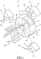
- the first preferred embodiment of a rolling device 1 includes an axle 2 rotatable about an axis (C), a plurality of first rolling members 3 connected fixedly to the axle 2 and angularly spaced apart from each other such that any two adjacent ones of the first rolling members 3 define an accommodating space 4 therebetween, a plurality of second rolling members 5 each disposed movably within the accommodating space 4 between two adjacent first rolling members 3, and a plurality of reinforcing units 6 each connected between two adjacent first rolling members 3.
- the first rolling members 3 cooperate with the second rolling members 5 to constitute a wheel body disposed around the axle 2.
- the number of the first rolling members 3 is three. That is, the rolling device 1 includes three accommodating spaces 4, three second rolling members 5, and three reinforcing units 6.
- Each first rolling member 3 includes a first body 30 having a first rolling surface 31 that is contactable with the ground surface.
- Each second rolling member 5 Includes a second body 50 having a second rolling surface 51 that is contactable with the ground surface, and a first positioning mechanism 52 disposed at the second body 50.
- Each second rolling member 5 is movable relative to the first rolling members 3 between a retracted position shown in Fig. 2 and an extended position shown in Fig. 3 .
- each reinforcing unit 6 includes two reinforcing walls 61 connected respectively to two opposite sides of each of the two adjacent first rolling members 3, and a second positioning mechanism 62 disposed on the two reinforcing walls 61.
- each second positioning mechanism 62 cooperates with the first positioning mechanism 52 of the corresponding second rolling member 5 to maintain the corresponding second rolling member 5 at a selected one of the retracted position and the extended position.
- each first positioning mechanism 52 includes a plurality of positioning holes 521 formed through the corresponding second body 50
- each second positioning mechanism 62 includes a plurality of positioning pins 621 each extending through the corresponding positioning hole 521 and two corresponding reinforcing walls 61.
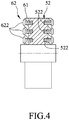
- each first positioning mechanism 52 may include a plurality of threaded holes 522 formed through the second body 50 of the corresponding second rolling member 5, and each second positioning mechanism 62 may include a plurality of positioning bolts 622 each extending through the corresponding threaded hole 522 and two corresponding reinforcing walls 61.
- each first rolling surface 31 is spaced apart from the axis (C) by a first radius L1
- each second rolling surface 51 is spaced apart from the axis (C) by a second radius L2.
- first and second rolling surfaces 31, 51 cooperate to allow the rolling device 1 to roll smoothly on a flat surface (A).
- the reinforcing walls 61 can promote the structural strength of the rolling device 1.
- each second rolling member 5 when moved on a stepped surface 7, each second rolling member 5 is disposed at the extended position, and projects partially from the corresponding accommodating space 4, so that the second radius L2 is more than the first radius L1.
- the stepped surface 7 has a first horizontal surface portion 71, a second horizontal surface portion 72 higher than the first horizontal surface portion 71, and a connecting surface portion 73 connected between the first and second horizontal surface portions 71, 72.
- the rolling device 1 is rolled on the first horizontal surface portion 71 toward the connecting surface portion 73, one of the second rolling members 5 may come into contact with the second horizontal surface portion 72 to allow the rolling device 1 to roll onto the second horizontal surface portion 72.
- the step-climbing function of the rolling device 1 can be affected by the height and inclination angle of the connecting surface portion 73.
- the rolling device 1 is suitable for use on a luggage case (not shown).
- each second rolling member 5 is disposed at the retracted position.
- each second rolling member 5 is disposed at the extended position.
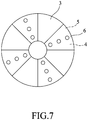
- the number of the first rolling members 3 may be changed according to different needs.
- the number of the first rolling members 3 may be increased to four, as shown in Fig. 7 .
- the number of the accommodating spaces 4, the second rolling members 5, and the reinforcing units 6 must be changed correspondingly.
- Figs. 8 and 9 show a second preferred embodiment of a rolling device not to the invention.
- the rolling device 1 further includes a plurality of resilient members 8 each disposed between the axle 2 and a respective one of the second rolling members 5, each second rolling members 5 further includes two spring-biased balls or pushbuttons 53 that are extendable from and retractable into the second body 50, and each reinforcing wall 61 is formed with a plurality of positioning holes 63.
- each resilient member 8 when no external force is applied, each resilient member 8 is in a fully stretched state, so that each spring-biased pushbutton 53 is disposed outwardly of the corresponding accommodating space 4 and is biased to project partially from the corresponding second body 50.
- the two spring-biased pushbuttons 53 can be pressed to allow the corresponding second rolling member 5 to be moved toward the axle (2) such that the two spring-biased pushbuttons 53 are in slidable contact with the corresponding reinforcing walls 61, as shown in Fig. 10 .
- the corresponding second rolling member 5 can be released to maintain the corresponding second rolling member 5 at a first position relative to the axle 2.
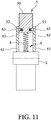
- the two spring-biased pushbuttons 53 may move to align respectively with another two of the positioning holes 63.
- the corresponding second rolling member 5 is released, it can be maintained at a second position.
- the positions of the second rolling members 5 can be adjusted easily without removal of the second positioning mechanisms 62 (see Fig. 1 ), so as to increase convenience during position adjustment. If desired, the number of the positioning holes 63 in each reinforcing wall 61 can be changed.
- the rolling device 1 has step-climbing function.
Description
- This invention relates to a rolling device, and more particularly to a rolling device having step-climbing function. A step-climbing wheel is known from
US 2011/0127732 A1 . A wheel or castor is a rolling device, has a circular outline, and is typically rotatable about a rotating axis. When the wheel is mounted to an article to be moved, and when the article is pushed or pulled, the wheel can roll on the ground surface. For example, when a plurality of castors are mounted to a luggage case, the luggage case can be moved conveniently in a labor-saving manner. - However, such a wheel is only suitable for rolling on a flat surface, and is difficult to use on a stepped surface. In the case of a luggage case, when it is desired to move the luggage case on the stepped surface, the luggage case must be lifted, thereby resulting in difficulty in moving the luggage case.
- The object of this invention is to provide a rolling device having step-climbing function.
- According to one aspect of this invention, a rolling device includes an axle rotatable about an axis, a plurality of first rolling members, and a plurality of second rolling members. The first rolling members are connected fixedly to the axle. Each of the first rolling members includes a first body having a first rolling surface that is contactable with the ground surface and that is spaced apart from the axis by a first radius. Any two adjacent ones of the first rolling members define an accommodating space therebetween. Each of the second rolling members is disposed movably within the accommodating space between two adjacent ones of the first rolling members. Each of the second rolling members includes a second body having a second rolling surface that is contactable with the ground surface and that is spaced apart from the axis by a second radius. Each of the second rolling members is movable relative to the first rolling members between a retracted position whereat the second radius is not more than the first radius, and an extended position whereat the second radius is more than the first radius. The rolling device further includes a plurality of reinforcing units each connected between two adjacent ones of the first rolling members. Each of the reinforcing units includes two reinforcing walls connected respectively to two opposite sides of each of two adjacent ones of the first rolling members. Each of the second rolling members further includes a first positioning mechanism disposed at the second body. Each of the reinforcing units further includes a second positioning mechanism disposed on the two reinforcing walls and cooperating with the first positioning mechanism of a corresponding one of the second rolling members to maintain a corresponding one of the second rolling members at a selected one of the retracted position and the extended position. The first positioning mechanism of each of the second rolling members includes a plurality of positioning holes formed through the second body of a corresponding one of the second rolling members, and the second positioning mechanism of each of the reinforcing units includes a plurality of positioning pins each extending through a corresponding one of the positioning holes and two corresponding ones of the reinforcing walls.
- According to another aspect of this invention, a rolling device includes an axle rotatable about an axis, a plurality of first rolling members, and a plurality of second rolling members. The first rolling members are connected fixedly to the axle. Each of the first rolling members includes a first body having a first rolling surface that is contactable with the ground surface and that is spaced apart from the axis by a first radius. Any two adjacent ones of the first rolling members define an accommodating space therebetween. Each of the second rolling members is disposed movably within the accommodating space between two adjacent ones of the first rolling members. Each of the second rolling members includes a second body having a second rolling surface that is contactable with the ground surface and that is spaced apart from the axis by a second radius. Each of the second rolling members is movable relative to the first rolling members between a retracted position whereat the second radius is not more than the first radius, and an extended position whereat the second radius is more than the first radius. The rolling device further includes a plurality of reinforcing units each connected between two adjacent ones of the first rolling members. Each of the reinforcing units includes two reinforcing walls connected respectively to two opposite sides of each of two adjacent ones of the first rolling members. Each of the second rolling members further includes a first positioning mechanism disposed at the second body. Each of the reinforcing units further includes a second positioning mechanism disposed on the two reinforcing walls and cooperating with the first positioning mechanism of a corresponding one of the second rolling members to maintain a corresponding one of the second rolling members at a selected one of the retracted position and the extended position. The first positioning mechanism of each of the second rolling members includes a plurality of threaded holes formed therethrough the second body of a corresponding one of the second rolling members, and the second positioning mechanism of each of the reinforcing units includes a plurality of positioning bolts each extending through a corresponding one of the threaded holes and two corresponding ones of the reinforcing walls.
- As such, in a situation where the rolling device is used on a stepped surface that has a first horizontal surface portion, a second horizontal surface portion higher than the first horizontal surface portion, and a connecting surface portion connected between the first and second horizontal surface portions, when each of the second rolling members is disposed at the extended position, and when the rolling device is rolled on the first horizontal surface portion toward the connecting surface portion, one of the second rolling members may come into contact with the second horizontal surface portion to allow the rolling device to roll onto the second horizontal surface portion.
- These and other features and advantages of this invention will become apparent in the following detailed description of the preferred embodiments of this invention, with reference to the accompanying drawings, in which:
-
Fig. 1 is an exploded perspective view of the first preferred embodiment of a rolling device according to this invention; -
Fig. 2 is a fragmentary sectional view of the first preferred embodiment, illustrating a retracted position of a second rolling member; -
Fig. 3 is a view similar toFig. 2 but illustrating an extended position of the second rolling member; -
Fig. 4 is a fragmentary sectional view illustrating modified first and second positioning mechanisms; -
Fig. 5 is a schematic side view of the first preferred embodiment, illustrating that the second rolling member is disposed at the retracted position when the rolling device is moved on a flat surface; -
Fig. 6 is schematic side view of the first preferred embodiment, illustrating that the second rolling member is disposed at the extended position when the rolling device is moved on a stepped surface; -
Fig. 7 is a schematic side view illustrating that the rolling device may include four second rolling members; -
Fig. 8 is a perspective view of a second embodiment of a rolling device not according to this invention; -
Fig. 9 is a fragmentary sectional view of the second embodiment, illustrating that two pushbuttons are biased to extend from a second body; -
Fig. 10 is a view similar toFig. 9 but illustrating the two pushbuttons are retracted into the second body; -
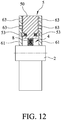
Fig. 11 is a view similar toFig. 10 but illustrating the two pushbuttons are biased to extend from the second body, and are engaged respectively into two positioning holes; and -
Fig. 12 is a view similar toFig. 11 but illustrating that the two pushbuttons are engaged respectively into another two positioning holes. - Before the present invention is described in greater detail in connection with the preferred embodiments, it should be noted that similar elements and structures are designated by like reference numerals throughout the entire disclosure.
- Referring to
Fig. 1 , the first preferred embodiment of arolling device 1 according to this invention includes anaxle 2 rotatable about an axis (C), a plurality of firstrolling members 3 connected fixedly to theaxle 2 and angularly spaced apart from each other such that any two adjacent ones of the first rollingmembers 3 define anaccommodating space 4 therebetween, a plurality of secondrolling members 5 each disposed movably within theaccommodating space 4 between two adjacent firstrolling members 3, and a plurality of reinforcingunits 6 each connected between two adjacent firstrolling members 3. The first rollingmembers 3 cooperate with the second rollingmembers 5 to constitute a wheel body disposed around theaxle 2. In this embodiment, the number of the first rollingmembers 3 is three. That is, therolling device 1 includes threeaccommodating spaces 4, three secondrolling members 5, and three reinforcingunits 6. - Each first rolling
member 3 includes afirst body 30 having a first rollingsurface 31 that is contactable with the ground surface. Each second rollingmember 5 Includes asecond body 50 having a second rollingsurface 51 that is contactable with the ground surface, and afirst positioning mechanism 52 disposed at thesecond body 50. Each second rollingmember 5 is movable relative to the first rollingmembers 3 between a retracted position shown inFig. 2 and an extended position shown inFig. 3 . - With particular reference to
Figs. 1 and2 , each reinforcingunit 6 includes two reinforcingwalls 61 connected respectively to two opposite sides of each of the two adjacent first rollingmembers 3, and asecond positioning mechanism 62 disposed on the two reinforcingwalls 61. - With particular reference to
Figs. 2 and 3 , eachsecond positioning mechanism 62 cooperates with thefirst positioning mechanism 52 of the corresponding second rollingmember 5 to maintain the corresponding second rollingmember 5 at a selected one of the retracted position and the extended position. In this embodiment, eachfirst positioning mechanism 52 includes a plurality ofpositioning holes 521 formed through the correspondingsecond body 50, and eachsecond positioning mechanism 62 includes a plurality ofpositioning pins 621 each extending through thecorresponding positioning hole 521 and twocorresponding reinforcing walls 61. Alternatively, with particular reference toFig. 4 , eachfirst positioning mechanism 52 may include a plurality of threadedholes 522 formed through thesecond body 50 of the corresponding secondrolling member 5, and eachsecond positioning mechanism 62 may include a plurality ofpositioning bolts 622 each extending through the corresponding threadedhole 522 and two correspondingreinforcing walls 61. - With particular reference to
Fig. 5 , each firstrolling surface 31 is spaced apart from the axis (C) by a first radius L1, and each secondrolling surface 51 is spaced apart from the axis (C) by a second radius L2. As shown inFig. 5 , when each secondrolling member 5 is disposed at the retracted position, it is retracted entirely into the corresponding accommodating space (C), so that the second radius L2 is not more than the first radius L1. In this state, since the second radius L2 is proximate to the first radius L1, the outline of therolling device 1 is generally circular. As such, the first and secondrolling surfaces rolling device 1 to roll smoothly on a flat surface (A). The reinforcingwalls 61 can promote the structural strength of therolling device 1. - With particular reference to
Fig. 6 , when moved on a stepped surface 7, each secondrolling member 5 is disposed at the extended position, and projects partially from the correspondingaccommodating space 4, so that the second radius L2 is more than the first radius L1. The stepped surface 7 has a firsthorizontal surface portion 71, a secondhorizontal surface portion 72 higher than the firsthorizontal surface portion 71, and aconnecting surface portion 73 connected between the first and secondhorizontal surface portions device 1 is rolled on the firsthorizontal surface portion 71 toward the connectingsurface portion 73, one of thesecond rolling members 5 may come into contact with the secondhorizontal surface portion 72 to allow therolling device 1 to roll onto the secondhorizontal surface portion 72. It should be noted that, the step-climbing function of the rollingdevice 1 can be affected by the height and inclination angle of the connectingsurface portion 73. - With particular reference to
Figs. 5 and6 , the rollingdevice 1 is suitable for use on a luggage case (not shown). When the suitable is moved on a flat surface (A), each second rollingmember 5 is disposed at the retracted position. When the suitable is moved on a stepped surface 7, each second rollingmember 5 is disposed at the extended position. - Alternatively, the number of the
first rolling members 3 may be changed according to different needs. For example, the number of thefirst rolling members 3 may be increased to four, as shown inFig. 7 . In this case, the number of theaccommodating spaces 4, thesecond rolling members 5, and the reinforcingunits 6 must be changed correspondingly. -
Figs. 8 and9 show a second preferred embodiment of a rolling device not to the invention. Unlike the first preferred embodiment, the rollingdevice 1 further includes a plurality ofresilient members 8 each disposed between theaxle 2 and a respective one of thesecond rolling members 5, eachsecond rolling members 5 further includes two spring-biased balls orpushbuttons 53 that are extendable from and retractable into thesecond body 50, and each reinforcingwall 61 is formed with a plurality of positioning holes 63. - With particular reference to
Fig. 9 , when no external force is applied, eachresilient member 8 is in a fully stretched state, so that each spring-biasedpushbutton 53 is disposed outwardly of the correspondingaccommodating space 4 and is biased to project partially from the correspondingsecond body 50. The two spring-biasedpushbuttons 53 can be pressed to allow the corresponding second rollingmember 5 to be moved toward the axle (2) such that the two spring-biasedpushbuttons 53 are in slidable contact with the corresponding reinforcingwalls 61, as shown inFig. 10 . With particular reference toFig. 11 , during movement of the corresponding second rollingmember 5 toward theaxle 2, as soon as the two spring-biasedpushbuttons 53 are aligned respectively with twopositioning holes 63, the corresponding second rollingmember 5 can be released to maintain the corresponding second rollingmember 5 at a first position relative to theaxle 2. When a force is applied to further press the corresponding second rollingmember 5, with particular reference toFig. 12 , the two spring-biasedpushbuttons 53 may move to align respectively with another two of the positioning holes 63. At this time, when the corresponding second rollingmember 5 is released, it can be maintained at a second position. - As such, by simply moving the
second rolling members 5 relative to theaxle 2, the positions of thesecond rolling members 5 can be adjusted easily without removal of the second positioning mechanisms 62 (seeFig. 1 ), so as to increase convenience during position adjustment. If desired, the number of the positioning holes 63 in each reinforcingwall 61 can be changed. - In view of the above, when each second rolling
member 5 is disposed at the extended position, the rollingdevice 1 has step-climbing function.
Claims (4)
- A rolling device (1) including an axle (2) rotatable about an axis (C), and a wheel body disposed around the axle (2), wherein the wheel body includes:a plurality of first rolling members (3) connected fixedly to the axle (2) and angularly spaced apart from each other, each of the first rolling members (3) including a first body (30) having a first rolling surface (31) that is contactable with the ground surface and that is spaced apart from the axis (C) by a first radius (L1), any two adjacent ones of the first rolling members (3) defining an accommodating space (4) therebetween; anda plurality of second rolling members (5) each disposed movably within the accommodating space (4) between two adjacent ones of the first rolling members (3), each of the second rolling members (5) including a second body (50) having a second rolling surface (51) that is contactable with the ground surface and that is spaced apart from the axis (C) by a second radius (L2), each of the second rolling members (5) being movable relative to the first rolling members (3) between a retracted position whereat the second radius (L2) is not more than the first radius (L1), and an extended position whereat the second radius (L2) is more than the first radius (L1);the rolling device (1) further including a plurality of reinforcing units (6) each connected between two adjacent ones of the first rolling members (3);wherein each of the reinforcing units (6) includes two reinforcing walls (61) connected respectively to two opposite sides of each of two adjacent ones of the first rolling members (3);wherein each of the second rolling members (5) further includes a first positioning mechanism (52) disposed at the second body (50), each of the reinforcing units (6) further including a second positioning mechanism (62) disposed on the two reinforcing walls (61) and cooperating with the first positioning mechanism (52) of a corresponding one of the second rolling members (5) to maintain a corresponding one of the second rolling members (5) at a selected one of the retracted position and the extended position; andthe rolling device (1) being characterized in that:the first positioning mechanism (52) of each of the second rolling members (5) includes a plurality of positioning holes (521) formed through the second body (50) of a corresponding one of the second rolling members (5), and the second positioning mechanism (62) of each of the reinforcing units (6) includes a plurality of positioning pins (621) each extending through a corresponding one of the positioning holes (521) and two corresponding ones of the reinforcing walls (61).
- The rolling device (1) as claimed in Claim 1, characterized in that the number of the first rolling members (3) is three.
- A rolling device (1) including an axle (2) rotatable about an axis (C), and a wheel body disposed around the axle (2), the wheel body including:a plurality of first rolling members (3) connected fixedly to the axle (2) and angularly spaced apart from each other, each of the first rolling members (3) including a first body (30) having a first rolling surface (31) that is contactable with the ground surface and that is spaced apart from the axis (C) by a first radius (L1), any two adjacent ones of the first rolling members (3) defining an accommodating space (4) therebetween; anda plurality of second rolling members (5) each disposed movably within the accommodating space (4) between two adjacent ones of the first rolling members (3), each of the second rolling members (5) including a second body (50) having a second rolling surface (51) that is contactable with the ground surface and that is spaced apart from the axis (C) by a second radius (L2), each of the second rolling members (5) being movable relative to the first rolling members (3) between a retracted position whereat the second radius (L2) is not more than the first radius (L1), and an extended position whereat the second radius (L2) is more than the first radius (L1);the rolling device (1) further including a plurality of reinforcing units (6) each connected between two adjacent ones of the first rolling members (3);wherein each of the reinforcing units (6) includes two reinforcing walls (61) connected respectively to two opposite sides of each of two adjacent ones of the first rolling members (3);wherein each of the second rolling members (5) further includes a first positioning mechanism (52) disposed at the second body (50), each of the reinforcing units (6) further including a second positioning mechanism (62) disposed on the two reinforcing walls (61) and cooperating with the first positioning mechanism (52) of a corresponding one of the second rolling members (5) to maintain a corresponding one of the second rolling members (5) at a selected one of the retracted position and the extended position; andthe rolling device (1) being characterized in that:the first positioning mechanism (52) of each of the second rolling members (5) includes a plurality of threaded holes (522) formed therethrough the second body (50) of a corresponding one of the second rolling members (5), and the second positioning mechanism (62) of each of the reinforcing units (6) includes a plurality of positioning bolts (622) each extending through a corresponding one of the threaded holes (522) and two corresponding ones of the reinforcing walls (61).
- The rolling device (1) as claimed in Claim 3, characterized in that the number of the first rolling members (3) is three.
Priority Applications (1)
| Application Number | Priority Date | Filing Date | Title |
|---|---|---|---|
| EP14162732.3A EP2927019B1 (en) | 2014-03-31 | 2014-03-31 | Rolling device having step-climbing function |
Applications Claiming Priority (1)
| Application Number | Priority Date | Filing Date | Title |
|---|---|---|---|
| EP14162732.3A EP2927019B1 (en) | 2014-03-31 | 2014-03-31 | Rolling device having step-climbing function |
Publications (2)
| Publication Number | Publication Date |
|---|---|
| EP2927019A1 EP2927019A1 (en) | 2015-10-07 |
| EP2927019B1 true EP2927019B1 (en) | 2017-08-30 |
Family
ID=50433996
Family Applications (1)
| Application Number | Title | Priority Date | Filing Date |
|---|---|---|---|
| EP14162732.3A Active EP2927019B1 (en) | 2014-03-31 | 2014-03-31 | Rolling device having step-climbing function |
Country Status (1)
| Country | Link |
|---|---|
| EP (1) | EP2927019B1 (en) |
Families Citing this family (1)
| Publication number | Priority date | Publication date | Assignee | Title |
|---|---|---|---|---|
| IT201800002050A1 (en) * | 2018-01-26 | 2019-07-26 | Andrea Belli | Rotates with movable elements |
Family Cites Families (4)
| Publication number | Priority date | Publication date | Assignee | Title |
|---|---|---|---|---|
| US7380618B2 (en) * | 2005-02-22 | 2008-06-03 | Gamma Two, Inc. | Stair climbing platform apparatus and method |
| US8764028B2 (en) * | 2009-11-30 | 2014-07-01 | Kevin Mann | Stair climbing wheel with multiple configurations |
| IT1402804B1 (en) * | 2010-10-20 | 2013-09-18 | Oto Melara Spa | WHEEL WITH VARIABLE DIAMETER. |
| CN203016107U (en) * | 2013-01-28 | 2013-06-26 | 赖百文 | Bearing and conveying device for luggage cases or luggage racks |
-
2014
- 2014-03-31 EP EP14162732.3A patent/EP2927019B1/en active Active
Non-Patent Citations (1)
| Title |
|---|
| None * |
Also Published As
| Publication number | Publication date |
|---|---|
| EP2927019A1 (en) | 2015-10-07 |
Similar Documents
| Publication | Publication Date | Title |
|---|---|---|
| USD855566S1 (en) | Charging stand for mobile devices | |
| USD930559S1 (en) | Display panel for automobile | |
| USD837855S1 (en) | Mobile service robot | |
| USD810750S1 (en) | Keyboard dock | |
| USD786742S1 (en) | Truck vehicle grille | |
| US10035688B1 (en) | Tire handling cart | |
| USD808894S1 (en) | Tire tread | |
| USD795761S1 (en) | Truck vehicle grille | |
| USD840478S1 (en) | Tire for a model vehicle | |
| USD817262S1 (en) | Tire tread | |
| USD870030S1 (en) | Tire | |
| USD813790S1 (en) | Tire tread | |
| US9976699B2 (en) | Load-adjustable display support device | |
| USD871972S1 (en) | Truck | |
| USD913910S1 (en) | Tire tread | |
| USD777872S1 (en) | Handgun slide with grooved design pattern | |
| USD827240S1 (en) | Height adjustable rolling storage cart | |
| EP2927019B1 (en) | Rolling device having step-climbing function | |
| USD933620S1 (en) | Television with rollable display | |
| GB2528962A (en) | Height adjustment arrangement | |
| US8434750B2 (en) | Positioning device for workpieces | |
| USD931344S1 (en) | Excavator undercarriage | |
| USD956710S1 (en) | Television with rollable display | |
| USD867219S1 (en) | Mobile beverage dispensary | |
| USD828927S1 (en) | Booth |
Legal Events
| Date | Code | Title | Description |
|---|---|---|---|
| PUAI | Public reference made under article 153(3) epc to a published international application that has entered the european phase |
Free format text: ORIGINAL CODE: 0009012 |
|
| 17P | Request for examination filed |
Effective date: 20150806 |
|
| AK | Designated contracting states |
Kind code of ref document: A1 Designated state(s): AL AT BE BG CH CY CZ DE DK EE ES FI FR GB GR HR HU IE IS IT LI LT LU LV MC MK MT NL NO PL PT RO RS SE SI SK SM TR |
|
| AX | Request for extension of the european patent |
Extension state: BA ME |
|
| RIC1 | Information provided on ipc code assigned before grant |
Ipc: A45C 5/14 20060101ALI20170126BHEP Ipc: B60B 19/04 20060101AFI20170126BHEP |
|
| GRAP | Despatch of communication of intention to grant a patent |
Free format text: ORIGINAL CODE: EPIDOSNIGR1 |
|
| INTG | Intention to grant announced |
Effective date: 20170320 |
|
| GRAS | Grant fee paid |
Free format text: ORIGINAL CODE: EPIDOSNIGR3 |
|
| GRAA | (expected) grant |
Free format text: ORIGINAL CODE: 0009210 |
|
| AK | Designated contracting states |
Kind code of ref document: B1 Designated state(s): AL AT BE BG CH CY CZ DE DK EE ES FI FR GB GR HR HU IE IS IT LI LT LU LV MC MK MT NL NO PL PT RO RS SE SI SK SM TR |
|
| REG | Reference to a national code |
Ref country code: GB Ref legal event code: FG4D |
|
| REG | Reference to a national code |
Ref country code: CH Ref legal event code: EP |
|
| REG | Reference to a national code |
Ref country code: AT Ref legal event code: REF Ref document number: 923139 Country of ref document: AT Kind code of ref document: T Effective date: 20170915 |
|
| REG | Reference to a national code |
Ref country code: IE Ref legal event code: FG4D |
|
| REG | Reference to a national code |
Ref country code: DE Ref legal event code: R096 Ref document number: 602014013697 Country of ref document: DE |
|
| REG | Reference to a national code |
Ref country code: FR Ref legal event code: PLFP Year of fee payment: 5 |
|
| REG | Reference to a national code |
Ref country code: NL Ref legal event code: MP Effective date: 20170830 |
|
| REG | Reference to a national code |
Ref country code: LT Ref legal event code: MG4D |
|
| REG | Reference to a national code |
Ref country code: AT Ref legal event code: MK05 Ref document number: 923139 Country of ref document: AT Kind code of ref document: T Effective date: 20170830 |
|
| PG25 | Lapsed in a contracting state [announced via postgrant information from national office to epo] |
Ref country code: SE Free format text: LAPSE BECAUSE OF FAILURE TO SUBMIT A TRANSLATION OF THE DESCRIPTION OR TO PAY THE FEE WITHIN THE PRESCRIBED TIME-LIMIT Effective date: 20170830 Ref country code: NO Free format text: LAPSE BECAUSE OF FAILURE TO SUBMIT A TRANSLATION OF THE DESCRIPTION OR TO PAY THE FEE WITHIN THE PRESCRIBED TIME-LIMIT Effective date: 20171130 Ref country code: HR Free format text: LAPSE BECAUSE OF FAILURE TO SUBMIT A TRANSLATION OF THE DESCRIPTION OR TO PAY THE FEE WITHIN THE PRESCRIBED TIME-LIMIT Effective date: 20170830 Ref country code: LT Free format text: LAPSE BECAUSE OF FAILURE TO SUBMIT A TRANSLATION OF THE DESCRIPTION OR TO PAY THE FEE WITHIN THE PRESCRIBED TIME-LIMIT Effective date: 20170830 Ref country code: AT Free format text: LAPSE BECAUSE OF FAILURE TO SUBMIT A TRANSLATION OF THE DESCRIPTION OR TO PAY THE FEE WITHIN THE PRESCRIBED TIME-LIMIT Effective date: 20170830 Ref country code: FI Free format text: LAPSE BECAUSE OF FAILURE TO SUBMIT A TRANSLATION OF THE DESCRIPTION OR TO PAY THE FEE WITHIN THE PRESCRIBED TIME-LIMIT Effective date: 20170830 |
|
| PG25 | Lapsed in a contracting state [announced via postgrant information from national office to epo] |
Ref country code: IS Free format text: LAPSE BECAUSE OF FAILURE TO SUBMIT A TRANSLATION OF THE DESCRIPTION OR TO PAY THE FEE WITHIN THE PRESCRIBED TIME-LIMIT Effective date: 20171230 Ref country code: LV Free format text: LAPSE BECAUSE OF FAILURE TO SUBMIT A TRANSLATION OF THE DESCRIPTION OR TO PAY THE FEE WITHIN THE PRESCRIBED TIME-LIMIT Effective date: 20170830 Ref country code: ES Free format text: LAPSE BECAUSE OF FAILURE TO SUBMIT A TRANSLATION OF THE DESCRIPTION OR TO PAY THE FEE WITHIN THE PRESCRIBED TIME-LIMIT Effective date: 20170830 Ref country code: BG Free format text: LAPSE BECAUSE OF FAILURE TO SUBMIT A TRANSLATION OF THE DESCRIPTION OR TO PAY THE FEE WITHIN THE PRESCRIBED TIME-LIMIT Effective date: 20171130 Ref country code: GR Free format text: LAPSE BECAUSE OF FAILURE TO SUBMIT A TRANSLATION OF THE DESCRIPTION OR TO PAY THE FEE WITHIN THE PRESCRIBED TIME-LIMIT Effective date: 20171201 Ref country code: RS Free format text: LAPSE BECAUSE OF FAILURE TO SUBMIT A TRANSLATION OF THE DESCRIPTION OR TO PAY THE FEE WITHIN THE PRESCRIBED TIME-LIMIT Effective date: 20170830 |
|
| PG25 | Lapsed in a contracting state [announced via postgrant information from national office to epo] |
Ref country code: NL Free format text: LAPSE BECAUSE OF FAILURE TO SUBMIT A TRANSLATION OF THE DESCRIPTION OR TO PAY THE FEE WITHIN THE PRESCRIBED TIME-LIMIT Effective date: 20170830 |
|
| PG25 | Lapsed in a contracting state [announced via postgrant information from national office to epo] |
Ref country code: DK Free format text: LAPSE BECAUSE OF FAILURE TO SUBMIT A TRANSLATION OF THE DESCRIPTION OR TO PAY THE FEE WITHIN THE PRESCRIBED TIME-LIMIT Effective date: 20170830 Ref country code: RO Free format text: LAPSE BECAUSE OF FAILURE TO SUBMIT A TRANSLATION OF THE DESCRIPTION OR TO PAY THE FEE WITHIN THE PRESCRIBED TIME-LIMIT Effective date: 20170830 Ref country code: PL Free format text: LAPSE BECAUSE OF FAILURE TO SUBMIT A TRANSLATION OF THE DESCRIPTION OR TO PAY THE FEE WITHIN THE PRESCRIBED TIME-LIMIT Effective date: 20170830 Ref country code: CZ Free format text: LAPSE BECAUSE OF FAILURE TO SUBMIT A TRANSLATION OF THE DESCRIPTION OR TO PAY THE FEE WITHIN THE PRESCRIBED TIME-LIMIT Effective date: 20170830 |
|
| PG25 | Lapsed in a contracting state [announced via postgrant information from national office to epo] |
Ref country code: SK Free format text: LAPSE BECAUSE OF FAILURE TO SUBMIT A TRANSLATION OF THE DESCRIPTION OR TO PAY THE FEE WITHIN THE PRESCRIBED TIME-LIMIT Effective date: 20170830 Ref country code: SM Free format text: LAPSE BECAUSE OF FAILURE TO SUBMIT A TRANSLATION OF THE DESCRIPTION OR TO PAY THE FEE WITHIN THE PRESCRIBED TIME-LIMIT Effective date: 20170830 Ref country code: EE Free format text: LAPSE BECAUSE OF FAILURE TO SUBMIT A TRANSLATION OF THE DESCRIPTION OR TO PAY THE FEE WITHIN THE PRESCRIBED TIME-LIMIT Effective date: 20170830 |
|
| REG | Reference to a national code |
Ref country code: DE Ref legal event code: R097 Ref document number: 602014013697 Country of ref document: DE |
|
| PLBE | No opposition filed within time limit |
Free format text: ORIGINAL CODE: 0009261 |
|
| STAA | Information on the status of an ep patent application or granted ep patent |
Free format text: STATUS: NO OPPOSITION FILED WITHIN TIME LIMIT |
|
| 26N | No opposition filed |
Effective date: 20180531 |
|
| PG25 | Lapsed in a contracting state [announced via postgrant information from national office to epo] |
Ref country code: SI Free format text: LAPSE BECAUSE OF FAILURE TO SUBMIT A TRANSLATION OF THE DESCRIPTION OR TO PAY THE FEE WITHIN THE PRESCRIBED TIME-LIMIT Effective date: 20170830 |
|
| REG | Reference to a national code |
Ref country code: FR Ref legal event code: PLFP Year of fee payment: 6 |
|
| REG | Reference to a national code |
Ref country code: DE Ref legal event code: R119 Ref document number: 602014013697 Country of ref document: DE |
|
| REG | Reference to a national code |
Ref country code: CH Ref legal event code: PL |
|
| PG25 | Lapsed in a contracting state [announced via postgrant information from national office to epo] |
Ref country code: MC Free format text: LAPSE BECAUSE OF FAILURE TO SUBMIT A TRANSLATION OF THE DESCRIPTION OR TO PAY THE FEE WITHIN THE PRESCRIBED TIME-LIMIT Effective date: 20170830 |
|
| REG | Reference to a national code |
Ref country code: BE Ref legal event code: MM Effective date: 20180331 |
|
| REG | Reference to a national code |
Ref country code: IE Ref legal event code: MM4A |
|
| PG25 | Lapsed in a contracting state [announced via postgrant information from national office to epo] |
Ref country code: LU Free format text: LAPSE BECAUSE OF NON-PAYMENT OF DUE FEES Effective date: 20180331 |
|
| PG25 | Lapsed in a contracting state [announced via postgrant information from national office to epo] |
Ref country code: DE Free format text: LAPSE BECAUSE OF NON-PAYMENT OF DUE FEES Effective date: 20181002 Ref country code: IE Free format text: LAPSE BECAUSE OF NON-PAYMENT OF DUE FEES Effective date: 20180331 |
|
| PG25 | Lapsed in a contracting state [announced via postgrant information from national office to epo] |
Ref country code: BE Free format text: LAPSE BECAUSE OF NON-PAYMENT OF DUE FEES Effective date: 20180331 Ref country code: LI Free format text: LAPSE BECAUSE OF NON-PAYMENT OF DUE FEES Effective date: 20180331 Ref country code: CH Free format text: LAPSE BECAUSE OF NON-PAYMENT OF DUE FEES Effective date: 20180331 |
|
| PG25 | Lapsed in a contracting state [announced via postgrant information from national office to epo] |
Ref country code: MT Free format text: LAPSE BECAUSE OF NON-PAYMENT OF DUE FEES Effective date: 20180331 |
|
| PG25 | Lapsed in a contracting state [announced via postgrant information from national office to epo] |
Ref country code: TR Free format text: LAPSE BECAUSE OF FAILURE TO SUBMIT A TRANSLATION OF THE DESCRIPTION OR TO PAY THE FEE WITHIN THE PRESCRIBED TIME-LIMIT Effective date: 20170830 |
|
| PG25 | Lapsed in a contracting state [announced via postgrant information from national office to epo] |
Ref country code: PT Free format text: LAPSE BECAUSE OF FAILURE TO SUBMIT A TRANSLATION OF THE DESCRIPTION OR TO PAY THE FEE WITHIN THE PRESCRIBED TIME-LIMIT Effective date: 20170830 |
|
| PG25 | Lapsed in a contracting state [announced via postgrant information from national office to epo] |
Ref country code: HU Free format text: LAPSE BECAUSE OF FAILURE TO SUBMIT A TRANSLATION OF THE DESCRIPTION OR TO PAY THE FEE WITHIN THE PRESCRIBED TIME-LIMIT; INVALID AB INITIO Effective date: 20140331 Ref country code: CY Free format text: LAPSE BECAUSE OF FAILURE TO SUBMIT A TRANSLATION OF THE DESCRIPTION OR TO PAY THE FEE WITHIN THE PRESCRIBED TIME-LIMIT Effective date: 20170830 Ref country code: MK Free format text: LAPSE BECAUSE OF NON-PAYMENT OF DUE FEES Effective date: 20170830 |
|
| PG25 | Lapsed in a contracting state [announced via postgrant information from national office to epo] |
Ref country code: AL Free format text: LAPSE BECAUSE OF FAILURE TO SUBMIT A TRANSLATION OF THE DESCRIPTION OR TO PAY THE FEE WITHIN THE PRESCRIBED TIME-LIMIT Effective date: 20170830 |
|
| PGFP | Annual fee paid to national office [announced via postgrant information from national office to epo] |
Ref country code: FR Payment date: 20230110 Year of fee payment: 10 |
|
| PGFP | Annual fee paid to national office [announced via postgrant information from national office to epo] |
Ref country code: IT Payment date: 20230321 Year of fee payment: 10 Ref country code: GB Payment date: 20230110 Year of fee payment: 10 |
|
| PGFP | Annual fee paid to national office [announced via postgrant information from national office to epo] |
Ref country code: GB Payment date: 20240111 Year of fee payment: 11 |