EP2926906A1 - Valve device and fluid handling device - Google Patents
Valve device and fluid handling device Download PDFInfo
- Publication number
- EP2926906A1 EP2926906A1 EP15160963.3A EP15160963A EP2926906A1 EP 2926906 A1 EP2926906 A1 EP 2926906A1 EP 15160963 A EP15160963 A EP 15160963A EP 2926906 A1 EP2926906 A1 EP 2926906A1
- Authority
- EP
- European Patent Office
- Prior art keywords
- closure means
- valve device
- component
- movement
- force
- Prior art date
- Legal status (The legal status is an assumption and is not a legal conclusion. Google has not performed a legal analysis and makes no representation as to the accuracy of the status listed.)
- Withdrawn
Links
Images


Classifications
-
- B—PERFORMING OPERATIONS; TRANSPORTING
- B01—PHYSICAL OR CHEMICAL PROCESSES OR APPARATUS IN GENERAL
- B01L—CHEMICAL OR PHYSICAL LABORATORY APPARATUS FOR GENERAL USE
- B01L3/00—Containers or dishes for laboratory use, e.g. laboratory glassware; Droppers
- B01L3/50—Containers for the purpose of retaining a material to be analysed, e.g. test tubes
- B01L3/502—Containers for the purpose of retaining a material to be analysed, e.g. test tubes with fluid transport, e.g. in multi-compartment structures
- B01L3/5021—Test tubes specially adapted for centrifugation purposes
-
- B—PERFORMING OPERATIONS; TRANSPORTING
- B01—PHYSICAL OR CHEMICAL PROCESSES OR APPARATUS IN GENERAL
- B01L—CHEMICAL OR PHYSICAL LABORATORY APPARATUS FOR GENERAL USE
- B01L2200/00—Solutions for specific problems relating to chemical or physical laboratory apparatus
- B01L2200/02—Adapting objects or devices to another
- B01L2200/026—Fluid interfacing between devices or objects, e.g. connectors, inlet details
-
- B—PERFORMING OPERATIONS; TRANSPORTING
- B01—PHYSICAL OR CHEMICAL PROCESSES OR APPARATUS IN GENERAL
- B01L—CHEMICAL OR PHYSICAL LABORATORY APPARATUS FOR GENERAL USE
- B01L2300/00—Additional constructional details
- B01L2300/04—Closures and closing means
- B01L2300/046—Function or devices integrated in the closure
- B01L2300/049—Valves integrated in closure
-
- B—PERFORMING OPERATIONS; TRANSPORTING
- B01—PHYSICAL OR CHEMICAL PROCESSES OR APPARATUS IN GENERAL
- B01L—CHEMICAL OR PHYSICAL LABORATORY APPARATUS FOR GENERAL USE
- B01L2300/00—Additional constructional details
- B01L2300/08—Geometry, shape and general structure
- B01L2300/0861—Configuration of multiple channels and/or chambers in a single devices
- B01L2300/087—Multiple sequential chambers
-
- B—PERFORMING OPERATIONS; TRANSPORTING
- B01—PHYSICAL OR CHEMICAL PROCESSES OR APPARATUS IN GENERAL
- B01L—CHEMICAL OR PHYSICAL LABORATORY APPARATUS FOR GENERAL USE
- B01L2400/00—Moving or stopping fluids
- B01L2400/04—Moving fluids with specific forces or mechanical means
- B01L2400/0403—Moving fluids with specific forces or mechanical means specific forces
- B01L2400/0409—Moving fluids with specific forces or mechanical means specific forces centrifugal forces
-
- B—PERFORMING OPERATIONS; TRANSPORTING
- B01—PHYSICAL OR CHEMICAL PROCESSES OR APPARATUS IN GENERAL
- B01L—CHEMICAL OR PHYSICAL LABORATORY APPARATUS FOR GENERAL USE
- B01L2400/00—Moving or stopping fluids
- B01L2400/06—Valves, specific forms thereof
- B01L2400/0605—Valves, specific forms thereof check valves
- B01L2400/0616—Ball valves
-
- B—PERFORMING OPERATIONS; TRANSPORTING
- B01—PHYSICAL OR CHEMICAL PROCESSES OR APPARATUS IN GENERAL
- B01L—CHEMICAL OR PHYSICAL LABORATORY APPARATUS FOR GENERAL USE
- B01L2400/00—Moving or stopping fluids
- B01L2400/06—Valves, specific forms thereof
- B01L2400/0633—Valves, specific forms thereof with moving parts
- B01L2400/065—Valves, specific forms thereof with moving parts sliding valves
Definitions
- the possibilities for the process control can be considerably expanded, for example, in a cartridge-based centrifugal system.
- liberated fluids may be retained in a defined space for a given time before the fluids are released along the intended fluidic pathway.
- Several liquids can be incubated with each other.
- These possibilities for carrying out various unit operations in biochemical processes allow the execution of complex processes in an automated manner, for example, complex binding or exchange processes or the dissolution of, for example, lyophilized substances can be carried out.
- the valve device according to the invention thus provides a resealable valve which offers great advantages, in particular for centrifugal systems.
- the closure means of the device according to the invention may be formed in one piece or two or more parts.
- a multi-part closure means may be provided, in which one of the parts consists of a sealing material or has a sealing material.
- an annular element may be provided of a suitable sealing material which is combined with another component which allows complete closure of the cavity.
- the sealing material can form the marginal region of the respective closure means, thereby ensuring optimum sealing of the opening of the cavity.
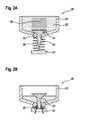
- Fig. 3 illustrates another example of a valve device 30 according to the invention.
- the closure means 31 is designed rod-shaped.
- the rod-shaped cross section of the closure means 31 closes the opening 34 of the cavity 32 of the component 33 (FIG. Fig. 3A ).
- the seal is optimized by a sealing ring 35.
- In the lower region of the rod-shaped closure means 31 there is a liquid-permeable region 39. With sufficient centrifugal force or equivalent force, the rod-shaped stopper 31 and the component 33 are moved downwards, the movement of the closure means 31 being limited by the movement limiting means 37 ( Fig. 3B ).
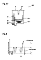
- a determination of the critical acceleration ⁇ 1 , ⁇ 2 , ⁇ 3 and ⁇ 4 depends in particular on the springs used and the properties of the respective cartridge mechanism and overall of the spring system.
- the critical accelerations can be selected from the following ranges, wherein it should be noted that ⁇ 1 ⁇ 2 ⁇ 3 ⁇ 4 should apply: 20 ⁇ G ⁇ ⁇ 1 ⁇ 150 ⁇ G 200 ⁇ G ⁇ ⁇ 2 ⁇ 600 ⁇ G 50 ⁇ G ⁇ ⁇ 3 ⁇ 3000 ⁇ G 3000 ⁇ G ⁇ ⁇ 4 ⁇ 6000 ⁇ G
Landscapes
- Health & Medical Sciences (AREA)
- Chemical & Material Sciences (AREA)
- Analytical Chemistry (AREA)
- General Health & Medical Sciences (AREA)
- Hematology (AREA)
- Clinical Laboratory Science (AREA)
- Chemical Kinetics & Catalysis (AREA)
- Centrifugal Separators (AREA)
- Automatic Analysis And Handling Materials Therefor (AREA)
Abstract
Bei einer Ventileinrichtung (30) mit wenigstens einem Verschlussmittel (31) und einem Bauteil (33), das wenigstens eine Kavität (32) aufweist, wobei das Verschlussmittel (31) zum Abdichten wenigstens einer Öffnung (34) in der Kavität vorgesehen ist, ist die Ventileinrichtung durch Zentrifugalkräfte oder gleichwirkende Kräfte betätigbar. Hierbei sind das Verschlussmittel (31) und das Bauteil (33) in Abhängigkeit von wirkenden Zentrifugalkräften oder gleichwirkenden Kräften beweglich gelagert. Für das Verschlussmittel (31) oder das Bauteil (33) ist wenigstens ein Bewegungsbegrenzungsmittel (37) vorgesehen, das die Bewegung des Verschlussmittels oder des Bauteils bei Überschreiten einer vorgebbaren Zentrifugalkraft oder gleichwirkenden Kraft begrenzt.In a valve device (30) having at least one closure means (31) and a component (33) having at least one cavity (32), wherein the closure means (31) is provided for sealing at least one opening (34) in the cavity is the valve device by centrifugal forces or equivalent forces operable. Here, the closure means (31) and the component (33) are movably mounted in response to acting centrifugal forces or equivalent forces. At least one movement-limiting means (37) is provided for the closure means (31) or the component (33) which limits the movement of the closure means or of the component when a predeterminable centrifugal force or equivalent force is exceeded.
Description
Die vorliegende Erfindung betrifft eine Ventileinrichtung mit wenigstens einem Verschlussmittel und einem Bauteil mit wenigstens einer Kavität, wobei das Verschlussmittel zum Abdichten wenigstens einer Öffnung der Kavität vorgesehen ist. Die Ventileinrichtung ist durch Zentrifugalkräfte oder gleichwirkende Kräfte betätigbar. Weiterhin betrifft die Erfindung die Verwendung einer solchen Ventileinrichtung sowie eine Vorrichtung zur Handhabung von Flüssigkeiten, die eine solche Ventileinrichtung umfasst.The present invention relates to a valve device having at least one closure means and a component having at least one cavity, wherein the closure means is provided for sealing at least one opening of the cavity. The valve device can be actuated by centrifugal forces or equivalent forces. Furthermore, the invention relates to the use of such a valve device and a device for handling liquids, comprising such a valve device.
Es sind bereits viele Systeme zur Automatisierung von chemischen oder biochemischen Prozessen und allgemein zur Handhabung von Flüssigkeiten bekannt. Die deutsche Offenlegungsschrift
Die Veröffentlichungsschrift der US-Patentanmeldung
Die Erfindung stellt eine mehrfach betätigbare Ventileinrichtung bereit, die durch Zentrifugalkräfte oder gleichwirkende Kräfte betätigbar ist. Diese Ventileinrichtung ist insbesondere für Systeme zur automatisierten Prozessierung von Flüssigkeiten geeignet, beispielsweise für kartuschenbasierte Systeme, die in einer Zentrifuge prozessiert werden. Die erfindungsgemäße Ventileinrichtung umfasst wenigstens ein Verschlussmittel und ein Bauteil mit wenigstens einer Kavität. Das Verschlussmittel ist zum Abdichten von wenigstens einer Öffnung der Kavität in dem Bauteil vorgesehen. Erfindungsgemäß sind das Verschlussmittel und das Bauteil in Abhängigkeit von wirkenden Zentrifugalkräften oder gleichwirkenden Kräfte beweglich gelagert. "Gleichwirkende Kräfte" können beispielsweise pneumatische Kräfte sein, die durch Anlegen von Druckluft bewirkt werden. Es ist wenigstens ein Bewegungsbegrenzungsmittel (Bewegungsstopp) für das Verschlussmittel und/oder das Bauteil vorgesehen, das die Bewegung des Verschlussmittels und/oder des Bauteils bei Überschreiten einer vorgebbaren Zentrifugalkraft oder einer gleichwirkenden Kraft begrenzt. Dadurch, dass sowohl das Bauteil als auch das Verschlussmittel im Prinzip beweglich gelagert sind, aber zumindest eines dieser Elemente in seiner Bewegung begrenzt ist, kommt es bei Kräften, die die Bewegung auslösen, zu einer unterschiedlich langen Bewegungsstrecke beider Elemente, wobei hierdurch eine Öffnung der zuvor verschlossenen Kavität erreicht wird. Vorzugsweise begrenzt das Bewegungsbegrenzungsmittel entweder die Bewegung des Verschlussmittels oder die des Bauteils. In bevorzugter Weise wirkt dabei die Bewegung des Bauteils und/oder des Verschlussmittels entgegen einer Rückstellkraft. Dies kann beispielsweise durch eine Federvorspannung des Bauteils und/oder des Verschlussmittels realisiert sein. Die Rückstellkraft ist dabei so ausgelegt, dass bei einer vorgebbaren Schwelle der Zentrifugalkraft oder gleichwirkenden Kraft die Rückstellkraft überstiegen wird, sodass die Bewegung des Bauteils und des Verschlussmittels ausgelöst wird und mithilfe des Bewegungsbegrenzungsmittels eine Offenposition der Ventileinrichtung erreicht wird. Bei einem Nachlassen der Zentrifugalkraft oder der gleichwirkenden Kraft übersteigt ab einem vorgebbaren Punkt die Rückstellkraft die Zentrifugalkraft oder gleichwirkende Kraft, sodass das Bauteil und/oder das Verschlussmittel wieder in die Ausgangslage, also in die Schließposition, zurückbewegt werden.The invention provides a multi-actuated valve device which can be actuated by centrifugal forces or equivalent forces. This valve device is particularly suitable for systems for the automated processing of liquids, for example for cartridge-based systems, which are processed in a centrifuge. The valve device according to the invention comprises at least one closure means and a component with at least one cavity. The closure means is provided for sealing at least one opening of the cavity in the component. According to the invention, the closure means and the component are movably mounted as a function of acting centrifugal forces or equivalent forces. "Equivalent forces" may be, for example, pneumatic forces caused by the application of compressed air. At least one movement limiting means (movement stop) is provided for the closure means and / or the component which controls the movement of the closure means and / or of the component when a predeterminable centrifugal force is exceeded or limited by an equivalent force. Characterized in that both the component and the closure means are mounted in principle movable, but at least one of these elements is limited in its movement, it comes at forces that trigger the movement to a different length of movement of both elements, thereby forming an opening of the previously closed cavity is reached. Preferably, the movement limiting means limits either the movement of the closure means or that of the component. In a preferred manner, the movement of the component and / or the closure means counteracts a restoring force. This can be realized for example by a spring bias of the component and / or the closure means. The restoring force is designed so that at a predefinable threshold of centrifugal force or equivalent force, the restoring force is exceeded, so that the movement of the component and the closure means is triggered and using the movement limiting means an open position of the valve device is achieved. When the centrifugal force or the equivalent force decreases, the restoring force exceeds the centrifugal force or equivalent force at a predeterminable point, so that the component and / or the closure means are moved back into the starting position, ie into the closed position.
Durch die mehrfach betätigbare Ventileinrichtung gemäß der Erfindung können beispielsweise in einem kartuschenbasierten Zentrifugalsystem die Möglichkeiten für die Prozessführung erheblich erweitert werden. Beispielsweise können freigesetzte Flüssigkeiten für eine bestimmte Zeit in einem definierten Raum zurückgehalten werden, bevor die Flüssigkeiten entlang des vorgesehenen fluidischen Pfades wieder freigesetzt werden. Es können mehrere Flüssigkeiten miteinander inkubiert werden. Beispielsweise ist es auch möglich, Flüssigkeiten mit einer Festphase zu inkubieren, wobei Flüssigkeiten mehrfach durch die Ventileinrichtung geführt werden können. Diese Möglichkeiten für die Durchführung von verschiedenen Einheitsoperationen bei biochemischen Prozessen erlauben die Durchführung von komplexen Abläufen in automatisierter Weise, beispielsweise können aufwendige Binde- oder Austauschprozesse oder das Lösen von beispielsweise lyophilisierten Stoffen durchgeführt werden. Die erfindungsgemäße Ventileinrichtung stellt damit ein wiederverschließbares Ventil bereit, das insbesondere für zentrifugale Systeme große Vorteile bietet.By virtue of the multiply operable valve device according to the invention, the possibilities for the process control can be considerably expanded, for example, in a cartridge-based centrifugal system. For example, liberated fluids may be retained in a defined space for a given time before the fluids are released along the intended fluidic pathway. Several liquids can be incubated with each other. For example, it is also possible to incubate liquids with a solid phase, wherein liquids can be repeatedly passed through the valve device. These possibilities for carrying out various unit operations in biochemical processes allow the execution of complex processes in an automated manner, for example, complex binding or exchange processes or the dissolution of, for example, lyophilized substances can be carried out. The valve device according to the invention thus provides a resealable valve which offers great advantages, in particular for centrifugal systems.
In einer besonders bevorzugten Ausführungsform der erfindungsgemäßen Ventileinrichtung ist ein weiteres Bewegungsbegrenzungsmittel für das Verschlussmittel und/oder für das Bauteil mit der wenigstens einen Kavität vorgesehen. Dieses weitere Bewegungsmittel begrenzt die Rückbewegung des Verschlussmittels und/oder des Bauteils, die bei Unterschreiten einer vorgebbaren Zentrifugalkraft oder gleichwirkenden Kraft einsetzt und die beispielsweise durch die beschriebene Rückstellkraft unterstützt werden kann. Durch die Rückbewegung des Verschlussmittels und/oder des Bauteils wird wieder die Ausgangsposition beziehungsweise Schließposition der Ventileinrichtung erreicht. Durch das weitere Begrenzungsmittel wird hierbei die Position des Verschlussmittels und/oder des Bauteils in einer bestimmten Position arretiert, sodass die Schließposition schnell und sicher erreicht wird. Vorzugsweise begrenzt das weitere Bewegungsbegrenzungsmittel entweder die Rückbewegung des Verschlussmittels oder die des Bauteils.In a particularly preferred embodiment of the valve device according to the invention, a further movement limiting means for the closure means and / or for the component with the at least one cavity is provided. This further movement means limits the return movement of the closure means and / or the component, which begins when falling below a predetermined centrifugal force or equivalent force and which can be supported for example by the restoring force described. By the return movement of the closure means and / or the component, the starting position or closing position of the valve device is again achieved. By the further limiting means in this case the position of the closure means and / or the component is locked in a certain position, so that the closed position is reached quickly and safely. Preferably, the further movement limiting means limits either the return movement of the closure means or that of the component.
Für die Realisierung der erfindungsgemäßen Ventileinrichtung sind vor allem zwei grundsätzliche Ausgestaltungen vorteilhaft. Bei der ersten prinzipiellen Ausgestaltung wird die Bewegung des Verschlussmittels begrenzt, sodass durch das Bewegungsbegrenzungsmittel das Verschlussmittel in eine Offenposition gezwungen wird. Vorteilhafterweise ist hierbei das Bauteil mit der wenigstens einen Kavität federvorgespannt, sodass es bei nachlassender Zentrifugalkraft oder der nachlassenden gleichwirkenden Kraft wieder in die Ausgangslage sicher zurückbewegt wird, wobei es zu einem Schließen der Ventileinrichtung kommt. In der anderen grundsätzlichen Ausgestaltung wird die Bewegung des Bauteils begrenzt, sodass es bei einem Überschreiten der vorgebbaren Zentrifugalkraft oder der gleichwirkenden Kraft zu einer Öffnung der Ventileinrichtung kommt. Vorteilhafterweise ist hierbei das Verschlussmittel federvorgespannt, wodurch es bei nachlassender Zentrifugalkraft oder gleichwirkenden Kraft wieder zu einem sicheren Verschluss der Ventileinrichtung kommt.For the realization of the valve device according to the invention, in particular two basic embodiments are advantageous. In the first basic embodiment, the movement of the closure means is limited, so that the closure means is forced by the movement limiting means in an open position. Advantageously, in this case the component is spring-biased with the at least one cavity, so that it is safely moved back to the starting position with decreasing centrifugal force or the decreasing equivalent force, resulting in a closing of the valve means. In the other basic embodiment, the movement of the component is limited so that it comes to an opening of the valve device when exceeding the predetermined centrifugal force or the same force acting. Advantageously, in this case the closure means is spring-biased, whereby it comes again to a safe closure of the valve device with decreasing centrifugal force or equivalent force.
Bei der erstgenannten Variante ist das Verschlussmittel vorzugsweise als kugelförmiger oder kegelförmiger oder keilförmiger oder stabförmiger Stöpsel ausgestaltet. Zur optimalen Abdichtung der Öffnung der Kavität kann eine Dichtung vorgesehen sein. Ein kugelförmiger Stöpsel befindet sich vorzugsweise innerhalb der Kavität und verschließt die Öffnung gewissermaßen von innen. Eine in der Kavität vorhandene Flüssigkeit kann durch den Druck der Flüssigkeitssäule auf den Stöpsel die Abdichtung verbessern. In vergleichbarer Weise kann der Stöpsel keil- oder kegelförmig ausgestaltet sein, wobei die Spitze eines solchen Stöpsels die Öffnung der Kavität durchragen kann. Für ein gutes Abdichten ist es vorteilhaft, wenn der Stöpsel eine möglichst hohe Masse aufweist, die in die Dichtung hineindrückt. Beispielsweise kann hierfür der Stöpsel aus einem Material gefertigt sein, das eine höhere Dichte als Wasser aufweist, beispielsweise Teflon oder POM (Polyoxymethylen). Als Dichtungsmaterial wird vorzugsweise ein elastisches Material wie beispielsweise Kautschuk gewählt, um eine gute Pressdichtung des Stöpsels gegenüber der Öffnung zu erreichen. Eine Ausgestaltung des Stöpsels in Keilform, also mit einer vergrößerten Fläche, die sich im Inneren der Kavität befindet, wird erreicht, dass die über dem Stöpsel liegende Flüssigkeitssäule verbreitert ist, sodass die zusätzliche Masse der Flüssigkeitssäule für einen erhöhten Anpressdruck in der Schließposition genutzt werden kann.In the former variant, the closure means is preferably designed as a spherical or conical or wedge-shaped or rod-shaped stopper. For optimal sealing of the opening of the cavity, a seal may be provided. A spherical plug is preferably located within the cavity and closes the opening from within, so to speak. A liquid present in the cavity can improve the seal by the pressure of the liquid column on the plug. Similarly, the plug may be wedge-shaped or tapered, with the tip of such a plug extending through the opening of the cavity. For a good sealing, it is advantageous if the stopper has the highest possible mass which presses into the seal. For example, for this purpose, the stopper may be made of a material having a higher density than water, for example Teflon or POM (polyoxymethylene). As the sealing material is preferably an elastic material such as rubber chosen to achieve a good press seal of the plug against the opening. An embodiment of the plug in a wedge shape, ie with an enlarged surface which is located in the interior of the cavity, is achieved in that the liquid column lying above the plug is widened so that the additional mass of the liquid column can be used for an increased contact pressure in the closed position ,
In der Ausgangsposition, in der die Zentrifugalkraft oder die gleichwirkende Kraft einen vorgebbaren Schwellenwert nicht überschreitet, befindet sich die Ventileinrichtung in Schließposition. Beim Überschreiten eines vorgebbaren Schwellenwertes für die wirkende Zentrifugalkraft oder die gleichwirkende Kraft bewegt sich sowohl das Bauteil mit der Kavität als auch das Verschlussmittel in Richtung der wirkenden Kraft. Das Bewegungsbegrenzungsmittel für das Verschlussmittel in der ersten prinzipiellen Ausgestaltung der erfindungsgemäßen Ventileinrichtung ist hierbei so ausgestaltet, dass ab einer bestimmten Länge des Bewegungspfades das Bewegungsbegrenzungsmittel die Bewegung des Verschlussmittels arretiert, sodass sich nur noch das Bauteil bewegt. Die Geometrien sind hierbei so gewählt, dass auf diese Weise eine Öffnung der Ventileinrichtung erreicht wird, wobei das Verschlussmittel durch die Öffnung der Kavität hindurch in eine Offenposition gedrückt wird. Dies kann beispielsweise durch ein stabförmiges Bewegungsbegrenzungsmittel erreicht werden, das im Durchmesser kleiner als die Öffnung der Kavität ist und das durch die Öffnung der Kavität hindurch beispielsweise den kugelförmigen Stöpsel zurückhält, sodass der Stöpsel die Öffnung nicht mehr verschließt. Flüssigkeiten können um den Stöpsel herum durch die Öffnung fließen und die Kavität verlassen. In einer anderen Ausgestaltung, insbesondere bei einem kegel- oder keilförmigen Stöpsel, kann das Bewegungsbegrenzungsmittel flächig ausgestaltet sein, sodass die durch die Öffnung der Kavität hindurch ragende Spitze des Stöpsels zurückgehalten wird, wodurch der Stöpsel aus der Öffnung teilweise herausgedrückt wird und es zu einer Öffnung und zu einem Fluidfluss kommt. Eine Federvorspannung des Bauteils kann in dieser Ausgestaltung beispielsweise so realisiert werden, dass eine Feder zwischen dem Bauteil und dem Bewegungsbegrenzungsmittel eingesetzt wird. Wenn die Zentrifugalkraft oder die gleichwirkende Kraft, die eine Öffnung des Ventils bewirkt hatte, einen vorgebbaren Schwellenwert unterschreitet, dominiert die Federkraft, sodass das Bauteil wieder in die Ausgangsposition zurückgedrückt wird.In the starting position, in which the centrifugal force or the equivalent force does not exceed a predefinable threshold value, the valve device is in the closed position. When a predefinable threshold for the acting centrifugal force or the equivalent force is exceeded, both the component with the cavity and the closure means moves in the direction of the acting force. The movement limiting means for the closure means in the first basic embodiment of the valve device according to the invention is in this case designed so that from a certain length of the movement path, the movement limiting means locks the movement of the closure means, so that only moves the component. The geometries are chosen so that in this way an opening of the valve device is achieved, wherein the closure means is pushed through the opening of the cavity through into an open position. This can be achieved, for example, by a rod-shaped movement limiting means which is smaller in diameter than the opening of the cavity and which, for example, retains the spherical plug through the opening of the cavity so that the plug no longer seals the opening. Liquids can flow around the plug through the opening and into the cavity leave. In another embodiment, in particular in the case of a conical or wedge-shaped stopper, the movement limiting means can be configured so that the tip of the stopper projecting through the opening of the cavity is retained, whereby the stopper is partially pushed out of the opening and becomes an opening and comes to a fluid flow. A spring bias of the component can be realized in this embodiment, for example, so that a spring between the component and the movement limiting means is used. If the centrifugal force or the equivalent force, which had caused an opening of the valve, falls below a predefinable threshold value, the spring force dominates, so that the component is pushed back into the starting position.
In einer besonders bevorzugten Ausgestaltung der erfindungsgemäßen Ventileinrichtung ist das Verschlussmittel im Wesentlichen als stabförmiger Stöpsel ausgestaltet, der in einem Teillängenabschnitt einen flüssigkeitsdurchlässigen Bereich aufweist. Dieser Längenabschnitt ist so angeordnet, dass sich dieser Längenabschnitt in der Schließposition außerhalb der Kavität und außerhalb der Öffnung der Kavität befindet. Wenn die Offenposition erreicht wird, befindet sich dieser Abschnitt innerhalb der Öffnung der Kavität, sodass Flüssigkeiten aus der Kavität über diesen Abschnitt nach außen gelangen können. Durch die wirkende Zentrifugalkraft oder gleichwirkende Kraft wird der Stöpsel gewissermaßen so verschoben, dass die Flüssigkeit den durchgängigen Bereich des stabförmigen Stöpsels erreichen kann. Der flüssigkeitsdurchlässige Bereich kann beispielsweise durch eine im Querschnitt teilkreisförmige Aussparung in diesem Abschnitt des Stöpsels realisiert sein. Die partielle Durchlässigkeit des Stöpsels kann aber auch auf andere Weise, beispielsweise durch eine oder mehrere Bohrungen in diesem Abschnitt, realisiert werden.In a particularly preferred embodiment of the valve device according to the invention, the closure means is designed substantially as a rod-shaped stopper which has a liquid-permeable region in a partial length section. This longitudinal section is arranged so that this longitudinal section is in the closed position outside the cavity and outside the opening of the cavity. When the open position is reached, this section is located within the cavity opening so that fluids from the cavity can escape through this section. By acting centrifugal force or equivalent force of the plug is shifted so to speak, that the liquid can reach the continuous portion of the rod-shaped plug. The liquid-permeable region can be realized, for example, by a cross-sectionally part-circular recess in this section of the stopper. However, the partial permeability of the stopper can also be realized in other ways, for example by means of one or more bores in this section.
Insbesondere in der Ausgestaltung mit einem stabförmigen Stöpsel mit einem flüssigkeitsdurchlässigen Bereich kann das bereits beschriebene weitere Begrenzungsmittel, das die Rückbewegung des Verschlussmittels beschränkt, vorteilhaft sein. Das weitere Bewegungsbegrenzungsmittel ist beispielsweise innerhalb der Kavität angeordnet und beispielsweise in Form eines Bewegungsanschlags ausgestaltet. Durch die Begrenzung der Rückbewegung wird der Stöpsel in der Verschlussposition genau positioniert, sodass sich der flüssigkeitsdurchlässige Bereich des Verschlussmittels außerhalb der Kavität befindet und die Abdichtung der Öffnung sicher gewährleistet ist.In particular, in the embodiment with a rod-shaped stopper with a liquid-permeable region, the already described further limiting means, which restricts the return movement of the closure means, may be advantageous. The further movement limiting means is arranged for example within the cavity and designed, for example, in the form of a movement stop. By limiting the return movement the stopper is accurately positioned in the closed position, so that the liquid-permeable area of the closure means is located outside the cavity and the sealing of the opening is assured.
Bei der weiter oben erwähnten zweiten prinzipiellen Variante der erfindungsgemäßen Ventileinrichtung begrenzt das Bewegungsbegrenzungsmittel die Bewegung des Bauteils mit der wenigstens einen Kavität. Zweckmäßigerweise verschließt in dieser Ausgestaltung das Verschlussmittel die Kavität von außen. Bei einem Überschreiten der vorgebbaren Zentrifugalkraft oder gleichwirkenden Kraft wird das Bauteil mit der Kavität durch das Bewegungsbegrenzungsmittel zurückgehalten und das Verschlussmittel bewegt sich in eine Offenposition, sodass Flüssigkeit die Kavität verlassen kann. Bei einer Entschleunigung der Zentrifuge oder allgemein, wenn die Zentrifugalkraft oder die gleichwirkende Kraft einen vorgebbaren Schwellenwert unterschreitet, dominiert die zweckmäßigerweise vorgesehene Rückstellkraft, die auf das Verschlussmittel wirkt, sodass wieder die Ausgangsposition, also die Schließposition, eingestellt wird. Mit besonderem Vorteil ist hierbei das bereits erwähnte weitere Bewegungsbegrenzungsmittel für die Rückbewegung des Bauteils vorgesehen, sodass die Rückbewegung des Bauteils nur bis zu dem entsprechend vorgesehenen Punkt erfolgt. Auf diese Weise kann die Schließposition in einer besonders präzisen Weise schnell wieder erreicht werden.In the above-mentioned second principal variant of the valve device according to the invention, the movement limiting means limits the movement of the component with the at least one cavity. Conveniently, in this embodiment, the closure means closes the cavity from the outside. When the predeterminable centrifugal force or equivalent force is exceeded, the component with the cavity is retained by the movement limiting means and the closure means moves into an open position so that liquid can leave the cavity. In a deceleration of the centrifuge or in general, when the centrifugal force or the equivalent force below a predetermined threshold, dominated by the appropriately provided restoring force acting on the closure means, so that the starting position, ie the closed position is adjusted again. With particular advantage, in this case, the already mentioned further movement limiting means for the return movement of the component is provided, so that the return movement of the component takes place only up to the correspondingly provided point. In this way, the closed position can be achieved quickly in a particularly precise manner again.
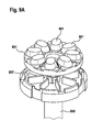
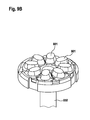
In einer bevorzugten Ausgestaltung der erfindungsgemäßen Ventileinrichtung ist eine Mehrzahl von Verschlussmitteln auf einem gemeinsamen Träger angeordnet. Beispielsweise kann eine Mehrzahl von Verschlussmitteln auf einem kreisförmigen Träger angeordnet sein, der auf einer gemeinsamen Feder gelagert ist. Mithilfe dieser Verschlussmittel können mehrere Kavitäten eines darüber angeordneten Bauteils von unten her verschlossen werden. Hierbei kann pro Öffnung einer Kavität ein Verschlussmittel vorgesehen sein. Es kann jedoch auch vorgesehen sein, dass mit einem Verschlussmittel mehrere Öffnungen, die einer oder gegebenenfalls mehreren Kavitäten zuzuordnen sind, verschlossen beziehungsweise geöffnet werden.In a preferred embodiment of the valve device according to the invention, a plurality of closure means is arranged on a common carrier. For example, a plurality of closure means may be arranged on a circular support which is mounted on a common spring. By means of this closure means, several cavities of a component arranged above can be closed from below. In this case, a closure means can be provided per opening of a cavity. However, provision may also be made for a closure means to close or open a plurality of openings which are to be assigned to one or possibly more cavities.
In einer besonders zweckmäßigen Ausgestaltung der erfindungsgemäßen Ventileinrichtung umfasst das Verschlussmittel eine reaktive Oberfläche, die insbesondere für chemische oder biochemische Prozesse, die mit der Vorrichtung, in die die erfindungsgemäße Ventileinrichtung integriert ist, durchgeführt werden sollen. Beispielsweise können Oberflächen mit immobilisierten Molekülen, z.B. Antikörpern, oder anderen reaktiven Substanzen vorgesehen sein, die für die Durchführung der vorgesehenen Verfahrensschritte eingesetzt werden können.In a particularly expedient embodiment of the valve device according to the invention, the closure means comprises a reactive surface which is to be carried out in particular for chemical or biochemical processes which are carried out with the device into which the valve device according to the invention is integrated. For example, surfaces with immobilized molecules, e.g. Antibodies, or other reactive substances may be provided, which can be used for carrying out the proposed method steps.
Das Verschlussmittel der erfindungsgemäßen Vorrichtung kann einteilig oder auch zwei- oder mehrteilig ausgebildet sein. Beispielsweise kann ein mehrteiliges Verschlussmittel vorgesehen sein, bei dem eines der Teile aus einem Dichtungsmaterial besteht oder ein Dichtungsmaterial aufweist. Insbesondere kann ein ringförmiges Element aus einem geeigneten Dichtungsmaterial vorgesehen sein, das zusammen mit einer weiteren Komponente, die den vollständigen Verschluss der Kavität ermöglicht, kombiniert wird. Das Dichtungsmaterial kann den randständigen Bereich des jeweiligen Verschlussmittels ausbilden, sodass hierdurch eine optimale Abdichtung der Öffnung der Kavität gewährleistet wird.The closure means of the device according to the invention may be formed in one piece or two or more parts. For example, a multi-part closure means may be provided, in which one of the parts consists of a sealing material or has a sealing material. In particular, an annular element may be provided of a suitable sealing material which is combined with another component which allows complete closure of the cavity. The sealing material can form the marginal region of the respective closure means, thereby ensuring optimum sealing of the opening of the cavity.
Die erfindungsgemäße Ventileinrichtung ist in besonders vorteilhafter Weise als Bestandteil eines Zentrifugalsystems geeignet, wobei mit der erfindungsgemäßen Ventileinrichtung ein wiederholtes Betätigen des Ventils möglich ist. Die Ventileinrichtung erweitert damit die Möglichkeiten insbesondere eines kartuschenbasierten Zentrifugalsystems für die automatisierte Durchführung von beispielsweise biochemischen oder chemischen Prozessen erheblich. Ein solches Zentrifugalsystem basiert insbesondere auf zwei oder mehr axial übereinander gelagerten Körpern (Revolvern), die in Abhängigkeit von einer Zentrifugalkraft oder einer gleichwirkenden Kraft gegeneinander verdrehbar sind. Hierbei ist mit "gleichwirkende Kraft" gemeint, dass die Kraft, wenn sie an das System angelegt wird, ein Verdrehen der Körper in Relation zueinander, wie es von einer entsprechenden Mechanik vorgesehen ist, auslöst. Dies kann beispielsweise durch Anlegen eines Drucks (Druckluft) erreicht werden. Für den Verdrehmechanismus einer solchen Vorrichtung kann beispielsweise eine sogenannte Kugelschreibermechanik vorgesehen sein, wobei ein Eingriff von Führungsfedern des einen Körpers in eine Profilzahnreihe des anderen Körpers und eine entgegen der Zentrifugalkraft oder entgegen der gleichwirkenden Kraft wirkende Rückstellkraft der Körper vorgesehen ist.The valve device according to the invention is suitable in a particularly advantageous manner as part of a centrifugal system, with the valve device according to the invention a repeated actuation of the valve is possible. The valve device thus considerably expands the possibilities, in particular of a cartridge-based centrifugal system, for the automated performance of, for example, biochemical or chemical processes. Such a centrifugal system is based in particular on two or more axially superimposed bodies (revolvers), which are rotatable relative to one another in dependence on a centrifugal force or an equivalent force. Herein, by "equivalent force" is meant that the force, when applied to the system, causes the bodies to rotate in relation to one another as provided by a corresponding mechanism. This can be achieved for example by applying a pressure (compressed air). For the twisting mechanism of such a device, for example, a so-called ballpoint pen mechanism may be provided, wherein an engagement of Guide springs of a body in a row of teeth of the other body and a counter to the centrifugal force or against the equivalent force acting restoring force of the body is provided.
Die Erfindung umfasst weiterhin die Verwendung der beschriebenen Ventileinrichtung für ein System zur Handhabung von Flüssigkeiten, wobei dieses System eine Mehrzahl von axial übereinander angeordneten Körpern umfasst, die in Abhängigkeit von einer Zentrifugalkraft oder einer gleichwirkenden Kraft gegeneinander verdrehbar sind. Schließlich umfasst die Erfindung eine Vorrichtung zur Handhabung von Flüssigkeiten mit einer Mehrzahl von axial übereinander angeordneten Körpern (Revolvern), die in Abhängigkeit von einer Zentrifugalkraft oder einer gleichwirkenden Kraft gegeneinander verdrehbar sind. Erfindungsgemäß umfasst diese Vorrichtung wenigstens eine Ventileinrichtung, wie sie vorliegend beschrieben ist. Die einzelnen Körper oder Revolver der Vorrichtung weisen jeweils wenigstens eine Kavität auf. Durch die Drehung der Revolver zueinander sind die einzelnen Kavitäten fluidisch miteinander koppelbar. Erfindungsgemäß wird wenigstens eine dieser fluidischen Kopplungen mittels der erfindungsgemäßen Ventileinrichtung realisiert. Diese Ventileinrichtung ist über die einstellbaren Beschleunigungswechsel der Zentrifuge oder einer gleichwirkenden Kraft zu betätigen. Der große Vorteil hierbei ist, dass diese Betätigung, also das Öffnen und Schließen des Ventils, mehrfach und im Prinzip unbegrenzt oft durchgeführt werden kann, wodurch die Möglichkeiten einer solchen Vorrichtung erheblich erweitert werden.The invention further comprises the use of the described valve device for a system for handling liquids, which system comprises a plurality of bodies arranged axially one above the other and which are rotatable relative to one another in dependence on a centrifugal force or an equivalent force. Finally, the invention comprises a device for handling liquids with a plurality of axially superposed bodies (revolvers), which are rotated in response to a centrifugal force or equivalent force against each other. According to the invention, this device comprises at least one valve device, as described herein. The individual bodies or revolvers of the device each have at least one cavity. As a result of the rotation of the revolvers with respect to one another, the individual cavities can be fluidly coupled to one another. According to the invention, at least one of these fluidic couplings is realized by means of the valve device according to the invention. This valve device is to be operated via the adjustable acceleration changes of the centrifuge or an equivalent force. The great advantage of this is that this operation, so the opening and closing of the valve, several times and in principle unlimited times can be performed, whereby the possibilities of such a device are considerably expanded.
Weitere Merkmale und Vorteile der Erfindung ergeben sich aus der nachfolgenden Beschreibung von Ausführungsbeispielen in Verbindung mit den Zeichnungen. Hierbei können die einzelnen Merkmale jeweils für sich oder in Kombination miteinander verwirklicht sein.Further features and advantages of the invention will become apparent from the following description of exemplary embodiments in conjunction with the drawings. In this case, the individual features can be implemented individually or in combination with each other.
In den Figuren zeigen:
- Fig. 1A/B
- schematische Darstellungen einer beispielhaften Ausgestaltung einer erfindungsgemäßen Ventileinrichtung mit kugelförmigem Verschlussmittel;
- Fig. 2A/B
- schematische Darstellungen einer erfindungsgemäßen Ventileinrichtung mit keilförmigem Verschlussmittel;
- Fig. 3A-C
- schematische Darstellungen einer erfindungsgemäßen Ventileinrichtung mit stabförmigem Verschlussmittel;
- Fig. 4
- Schnittdarstellung einer beispielhaften Ausgestaltung eines flüssigkeitsdurchlässigen Bereiches eines Verschlussmittels für eine erfindungsgemäße Ventileinrichtung;
- Fig. 5A-C
- schematische Darstellungen der Integration einer erfindungsgemäßen Ventileinrichtung in den Revolver eines Zentrifugalsystems für ein Bead-basiertes Prozessierungsprotokoll;
- Fig. 6
- zeitlicher Verlauf der Zentrifugationsschritte für ein Bead-basiertes Prozessierungsprotokoll;
- Fig. 7A-C
- schematische Darstellungen einer beispielhaften Ausgestaltung einer erfindungsgemäßen Ventileinrichtung mit federkraftunterstütztem Verschlussmittel;
- Fig. 8A/B
- isometrische Außenansicht (A) und Schnittansicht (B) einer beispielhaften Ausgestaltung der Körper eines Zentrifugalsystem mit erfindungsgemäßer Ventileinrichtung;
- Fig. 9A/B
- isometrische Darstellungen einer erfindungsgemäßen Ventileinrichtung mit einer Mehrzahl von Verschlussmitteln und
- Fig. 10A/B
- isometrische Darstellungen einer erfindungsgemäßen Ventileinrichtung mit einer Mehrzahl von mehrteilig zusammengesetzten Verschlussmitteln.
- Fig. 1A / B
- schematic representations of an exemplary embodiment of a valve device according to the invention with spherical closure means;
- Fig. 2A / B
- schematic representations of a valve device according to the invention with wedge-shaped closure means;
- Fig. 3A-C
- schematic representations of a valve device according to the invention with rod-shaped closure means;
- Fig. 4
- Sectional view of an exemplary embodiment of a liquid-permeable region of a closure means for a valve device according to the invention;
- Fig. 5A-C
- schematic representations of the integration of a valve device according to the invention in the turret of a bead- based processing protocol centrifugal system;
- Fig. 6
- time course of the centrifugation steps for a bead- based processing protocol;
- Fig. 7A-C
- schematic representations of an exemplary embodiment of a valve device according to the invention with spring-assisted closure means;
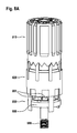
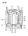
- Fig. 8A / B
- Isometric view (A) and sectional view (B) of an exemplary embodiment of the body of a centrifugal system with valve device according to the invention;
- Fig. 9A / B
- Isometric views of a valve device according to the invention with a plurality of closure means and
- Fig. 10A / B
- Isometric representations of a valve device according to the invention with a plurality of multi-part composite closure means.
Bei der Rückbewegung des Bauteils kann es allgemein vorgesehen sein, dass die Feder 38 unmittelbar nur auf das Bauteil 33 wirkt. Es ist jedoch zweckmäßig, dass der Stöpsel 31 beispielsweise durch eine Presspassung, die eine Abdichtung bewirkt, verhältnismäßig fest mit dem Bauteil 33 verbunden ist, sodass der Stöpsel bei der Rückbewegung des Bauteils ebenfalls bewegt wird. In anderen Ausführungsformen ist es auch möglich, dass die Federkraft unmittelbar auf das Bauteil und das Verschlussmittel wirkt.In the return movement of the component, it can generally be provided that the
Eine erfindungsgemäße Ventileinrichtung kann beispielsweise in einem Zentrifugalsystem für die automatisierte Prozessierung von Bead-basierten Assays verwendet werden. Für eine maximale Wechselwirkung der Beads mit den Reagenzien, beispielsweise für eine Adsorption oder für eine Reaktion von Wechselwirkungspartner, ist häufig eine gewisse Austauschdauer notwendig (Inkubationszeit). Die Erfordernisse für eine optimale Prozessführung können mithilfe einer erfindungsgemäßen Ventileinrichtung in besonders vorteilhafter Weise realisiert werden. Insbesondere kann hierdurch gewährleistet werden, dass die Beads mit der sie umgebenden Flüssigkeit mehrfach in Kontakt gebracht und durchmischt werden.
Eine Festlegung der kritischen Beschleunigung ω1, ω2, ω3 und ω4 hängt insbesondere von den verwendeten Federn und den Eigenschaften der jeweiligen Kartuschenmechanik und insgesamt des Federsystems ab. Beispielsweise können die kritischen Beschleunigungen aus den folgenden Bereichen gewählt werden, wobei zu beachten ist, dass ω1 < ω2 < ω3 < ω4 gelten sollte: ![]()
![]()
![]()
![]()
![]()
![]()
![]()
![]()
Eine Integration dieses Prinzips einer erfindungsgemäßen Ventileinrichtung in eine zentrifugalgesteuerte Kartuschenmechanik ist in
In bevorzugten Ausgestaltungen können die Verschlussmittel 801 mit reaktiven Oberflächen ausgestattet sein. Es kann beispielsweise vorgesehen sein, dass das Verschlussmittel 801 zumindest teilweise aus einem Polymer gebildet ist, das gleichzeitig die reaktive Oberfläche darstellt. Andererseits sind auch verschiedene Beschichtungen oder Ähnliches der Verschlussmittel 801 möglich. Reaktive Oberflächen können beispielsweise für die Durchführung von Immunoassays eingesetzt werden. Beispielsweise können als reaktive Oberflächen Träger mit immobilisierten Antikörpern eingesetzt werden, die für den Nachweis bestimmter Antigene im Rahmen von Immunoassays verwendet werden. Derartige Immunoassays erfordern wiederholte Inkubationen verschiedener Substanzen miteinander und gegebenenfalls mit einer reaktiven Oberfläche. Mit den erfindungsgemäßen Ventileinrichtungen können solche wiederholten Inkubationen von Flüssigkeiten mit einer reaktiven Oberfläche in besonders vorteilhafter Weise durchgeführt werden. Hierbei können in zentrifugalgesteuerter Weise verschiedene Flüssigkeiten untereinander oder Flüssigkeiten mit der reaktiven Oberfläche für eine definierte Zeit in Kontakt gebracht werden.In preferred embodiments, the closure means 801 may be provided with reactive surfaces. It can be provided, for example, that the closure means 801 is at least partially formed from a polymer, which at the same time represents the reactive surface. On the other hand, various coatings or the like of the closure means 801 are possible. Reactive surfaces can be used, for example, for carrying out immunoassays. For example, immobilized antibodies used for the detection of certain antigens in the context of immunoassays can be used as reactive surfaces. Such immunoassays require repeated incubations of various substances with one another and optionally with a reactive surface. With the valve devices according to the invention, such repeated incubations of liquids with a reactive surface can be carried out in a particularly advantageous manner. Here, in centrifugally controlled manner, different liquids can be brought into contact with each other or liquids with the reactive surface for a defined time.
Claims (15)
Applications Claiming Priority (1)
| Application Number | Priority Date | Filing Date | Title |
|---|---|---|---|
| DE102014206526.7A DE102014206526A1 (en) | 2014-04-04 | 2014-04-04 | Valve device and device for handling liquids |
Publications (1)
| Publication Number | Publication Date |
|---|---|
| EP2926906A1 true EP2926906A1 (en) | 2015-10-07 |
Family
ID=53174780
Family Applications (1)
| Application Number | Title | Priority Date | Filing Date |
|---|---|---|---|
| EP15160963.3A Withdrawn EP2926906A1 (en) | 2014-04-04 | 2015-03-26 | Valve device and fluid handling device |
Country Status (2)
| Country | Link |
|---|---|
| EP (1) | EP2926906A1 (en) |
| DE (1) | DE102014206526A1 (en) |
Cited By (1)
| Publication number | Priority date | Publication date | Assignee | Title |
|---|---|---|---|---|
| WO2021043567A1 (en) * | 2019-09-03 | 2021-03-11 | Robert Bosch Gmbh | Centrifuge unit for a microfluidic device for processing liquid samples |
Citations (6)
| Publication number | Priority date | Publication date | Assignee | Title |
|---|---|---|---|---|
| US20070134799A1 (en) | 1998-08-12 | 2007-06-14 | Schembri Carol T | Method and apparatus for controlling reactions |
| US20080164204A1 (en) * | 2007-01-08 | 2008-07-10 | Mehdi Hatamian | Valve for facilitating and maintaining separation of fluids and materials |
| WO2011069145A2 (en) * | 2009-12-04 | 2011-06-09 | Becton, Dickinson And Company | Blood collection tube with separation barrier |
| DE102010003223A1 (en) | 2010-03-24 | 2011-09-29 | Albert-Ludwigs-Universität Freiburg | Device for insertion into a rotor of a centrifuge, centrifuge and method for fluidic coupling of cavities |
| WO2013042435A1 (en) * | 2011-09-20 | 2013-03-28 | 富士紡ホールディングス株式会社 | Reagent container |
| EP2647436A2 (en) * | 2012-04-04 | 2013-10-09 | Robert Bosch GmbH | Revolver component for a reagent container |
-
2014
- 2014-04-04 DE DE102014206526.7A patent/DE102014206526A1/en not_active Withdrawn
-
2015
- 2015-03-26 EP EP15160963.3A patent/EP2926906A1/en not_active Withdrawn
Patent Citations (7)
| Publication number | Priority date | Publication date | Assignee | Title |
|---|---|---|---|---|
| US20070134799A1 (en) | 1998-08-12 | 2007-06-14 | Schembri Carol T | Method and apparatus for controlling reactions |
| US20080164204A1 (en) * | 2007-01-08 | 2008-07-10 | Mehdi Hatamian | Valve for facilitating and maintaining separation of fluids and materials |
| WO2011069145A2 (en) * | 2009-12-04 | 2011-06-09 | Becton, Dickinson And Company | Blood collection tube with separation barrier |
| DE102010003223A1 (en) | 2010-03-24 | 2011-09-29 | Albert-Ludwigs-Universität Freiburg | Device for insertion into a rotor of a centrifuge, centrifuge and method for fluidic coupling of cavities |
| WO2013042435A1 (en) * | 2011-09-20 | 2013-03-28 | 富士紡ホールディングス株式会社 | Reagent container |
| EP2759837A1 (en) * | 2011-09-20 | 2014-07-30 | Fujibo Holdings Inc. | Reagent container |
| EP2647436A2 (en) * | 2012-04-04 | 2013-10-09 | Robert Bosch GmbH | Revolver component for a reagent container |
Cited By (3)
| Publication number | Priority date | Publication date | Assignee | Title |
|---|---|---|---|---|
| WO2021043567A1 (en) * | 2019-09-03 | 2021-03-11 | Robert Bosch Gmbh | Centrifuge unit for a microfluidic device for processing liquid samples |
| CN114585844A (en) * | 2019-09-03 | 2022-06-03 | 罗伯特·博世有限公司 | Centrifugal unit for a microfluidic device for processing liquid samples |
| CN114585844B (en) * | 2019-09-03 | 2024-09-24 | 罗伯特·博世有限公司 | Centrifugal unit for a microfluidic device for processing liquid samples |
Also Published As
| Publication number | Publication date |
|---|---|
| DE102014206526A1 (en) | 2015-10-08 |
Similar Documents
| Publication | Publication Date | Title |
|---|---|---|
| EP2322277B1 (en) | Microfluid chip | |
| EP2389529A1 (en) | Valve, in particular for a component in microfluid technology | |
| EP3694645B1 (en) | Device having a first and a second chamber for receiving a body fluid | |
| EP3452217A1 (en) | Fluid handling device and method for fluid handling | |
| EP2647433B1 (en) | Reagent container insert part and reagent container | |
| DE102011077101A1 (en) | Microfluidic system and method of operating such a system | |
| DE60104485T2 (en) | Pyrotechnic actuator with deformable membrane | |
| WO2011076469A1 (en) | Magnetic valve and driver assistance device comprising said type of magnetic valve | |
| EP3406340A1 (en) | Flow cell with housing component | |
| WO2021018341A1 (en) | Valve, device for regulating the pressure of a flow medium using the valve, and device for securing the valve in a transmission component | |
| DE1935394C3 (en) | Pressure reducers, in particular for hydraulic vehicle brake systems | |
| EP2926906A1 (en) | Valve device and fluid handling device | |
| DE3446408C2 (en) | Lockable gas spring | |
| EP2692440A1 (en) | Reagent container insert, reagent container, method for centrifuging at least one material and method for pressure treating at least one material | |
| DE102013220264A1 (en) | Method for mixing liquids and microfluidic centrifugal system | |
| EP2879791A1 (en) | Revolver component for a reagent vessel, reagent vessel part and reagent vessel for a centrifuge and/or for a pressure-varying device | |
| DE102015203779A1 (en) | Device for the automated processing of liquids | |
| EP2774677A2 (en) | Device for performing chemical and/or biochemical processes | |
| WO2013149762A1 (en) | Chamber component for a reagent vessel, and use thereof | |
| EP2194300A1 (en) | Non-return valve for hydraulic power steering | |
| DE102019120221A1 (en) | Valve for regulating pressures of a fluid | |
| DE102015104258A1 (en) | Valve, in particular servo valve | |
| DE2046377A1 (en) | Valve arrangement | |
| DE19946654B4 (en) | Valve for liquid separation technology | |
| DE3518659A1 (en) | Valve |
Legal Events
| Date | Code | Title | Description |
|---|---|---|---|
| PUAI | Public reference made under article 153(3) epc to a published international application that has entered the european phase |
Free format text: ORIGINAL CODE: 0009012 |
|
| AK | Designated contracting states |
Kind code of ref document: A1 Designated state(s): AL AT BE BG CH CY CZ DE DK EE ES FI FR GB GR HR HU IE IS IT LI LT LU LV MC MK MT NL NO PL PT RO RS SE SI SK SM TR |
|
| AX | Request for extension of the european patent |
Extension state: BA ME |
|
| 17P | Request for examination filed |
Effective date: 20160407 |
|
| RBV | Designated contracting states (corrected) |
Designated state(s): AL AT BE BG CH CY CZ DE DK EE ES FI FR GB GR HR HU IE IS IT LI LT LU LV MC MK MT NL NO PL PT RO RS SE SI SK SM TR |
|
| STAA | Information on the status of an ep patent application or granted ep patent |
Free format text: STATUS: THE APPLICATION IS DEEMED TO BE WITHDRAWN |
|
| 18D | Application deemed to be withdrawn |
Effective date: 20160408 |