EP2925236B1 - Suture delivery system - Google Patents
Suture delivery system Download PDFInfo
- Publication number
- EP2925236B1 EP2925236B1 EP13795203.2A EP13795203A EP2925236B1 EP 2925236 B1 EP2925236 B1 EP 2925236B1 EP 13795203 A EP13795203 A EP 13795203A EP 2925236 B1 EP2925236 B1 EP 2925236B1
- Authority
- EP
- European Patent Office
- Prior art keywords
- guide
- anchor
- suture
- driver
- diameter
- Prior art date
- Legal status (The legal status is an assumption and is not a legal conclusion. Google has not performed a legal analysis and makes no representation as to the accuracy of the status listed.)
- Active
Links
- 210000000683 abdominal cavity Anatomy 0.000 claims description 24
- 239000000463 material Substances 0.000 claims description 19
- 230000000694 effects Effects 0.000 claims description 18
- 238000012800 visualization Methods 0.000 claims description 2
- 210000003815 abdominal wall Anatomy 0.000 description 65
- 230000007547 defect Effects 0.000 description 24
- 230000033001 locomotion Effects 0.000 description 19
- 210000000056 organ Anatomy 0.000 description 14
- 210000001519 tissue Anatomy 0.000 description 14
- 230000000670 limiting effect Effects 0.000 description 11
- 230000008878 coupling Effects 0.000 description 10
- 238000010168 coupling process Methods 0.000 description 10
- 238000005859 coupling reaction Methods 0.000 description 10
- 238000000034 method Methods 0.000 description 10
- HLXZNVUGXRDIFK-UHFFFAOYSA-N nickel titanium Chemical compound [Ti].[Ti].[Ti].[Ti].[Ti].[Ti].[Ti].[Ti].[Ti].[Ti].[Ti].[Ni].[Ni].[Ni].[Ni].[Ni].[Ni].[Ni].[Ni].[Ni].[Ni].[Ni].[Ni].[Ni].[Ni] HLXZNVUGXRDIFK-UHFFFAOYSA-N 0.000 description 9
- 229910001000 nickel titanium Inorganic materials 0.000 description 9
- 210000003491 skin Anatomy 0.000 description 9
- 238000004873 anchoring Methods 0.000 description 8
- 230000004048 modification Effects 0.000 description 7
- 238000012986 modification Methods 0.000 description 7
- 229920000642 polymer Polymers 0.000 description 7
- 230000000717 retained effect Effects 0.000 description 7
- 230000003187 abdominal effect Effects 0.000 description 6
- 230000008901 benefit Effects 0.000 description 6
- 238000011065 in-situ storage Methods 0.000 description 6
- 229920001610 polycaprolactone Polymers 0.000 description 5
- 239000004632 polycaprolactone Substances 0.000 description 5
- 238000001356 surgical procedure Methods 0.000 description 5
- 230000000007 visual effect Effects 0.000 description 5
- 230000001419 dependent effect Effects 0.000 description 4
- 238000013461 design Methods 0.000 description 4
- 230000014759 maintenance of location Effects 0.000 description 4
- 230000007115 recruitment Effects 0.000 description 4
- 230000009471 action Effects 0.000 description 3
- 238000007373 indentation Methods 0.000 description 3
- 239000003550 marker Substances 0.000 description 3
- 230000008569 process Effects 0.000 description 3
- 230000002829 reductive effect Effects 0.000 description 3
- 230000000284 resting effect Effects 0.000 description 3
- 239000007787 solid Substances 0.000 description 3
- 239000012780 transparent material Substances 0.000 description 3
- 240000007817 Olea europaea Species 0.000 description 2
- 208000031481 Pathologic Constriction Diseases 0.000 description 2
- 229920000954 Polyglycolide Polymers 0.000 description 2
- 230000008859 change Effects 0.000 description 2
- 238000010276 construction Methods 0.000 description 2
- 229920001577 copolymer Polymers 0.000 description 2
- 230000000593 degrading effect Effects 0.000 description 2
- 239000013536 elastomeric material Substances 0.000 description 2
- 210000003195 fascia Anatomy 0.000 description 2
- 230000006870 function Effects 0.000 description 2
- 238000002357 laparoscopic surgery Methods 0.000 description 2
- 238000012830 laparoscopic surgical procedure Methods 0.000 description 2
- 230000007246 mechanism Effects 0.000 description 2
- 239000000203 mixture Substances 0.000 description 2
- RVTZCBVAJQQJTK-UHFFFAOYSA-N oxygen(2-);zirconium(4+) Chemical compound [O-2].[O-2].[Zr+4] RVTZCBVAJQQJTK-UHFFFAOYSA-N 0.000 description 2
- 229920001606 poly(lactic acid-co-glycolic acid) Polymers 0.000 description 2
- 229920002463 poly(p-dioxanone) polymer Polymers 0.000 description 2
- 239000000622 polydioxanone Substances 0.000 description 2
- 239000004626 polylactic acid Substances 0.000 description 2
- 229910001220 stainless steel Inorganic materials 0.000 description 2
- 239000010935 stainless steel Substances 0.000 description 2
- 239000003356 suture material Substances 0.000 description 2
- 230000007704 transition Effects 0.000 description 2
- 210000001835 viscera Anatomy 0.000 description 2
- PJRSUKFWFKUDTH-JWDJOUOUSA-N (2s)-6-amino-2-[[2-[[(2s)-2-[[(2s,3s)-2-[[(2s)-2-[[2-[[(2s)-2-[[(2s)-6-amino-2-[[(2s)-2-[[(2s)-2-[[(2s)-2-[(2-aminoacetyl)amino]-4-methylsulfanylbutanoyl]amino]propanoyl]amino]-3-hydroxypropanoyl]amino]hexanoyl]amino]propanoyl]amino]acetyl]amino]propanoyl Chemical compound CSCC[C@H](NC(=O)CN)C(=O)N[C@@H](C)C(=O)N[C@@H](CO)C(=O)N[C@@H](CCCCN)C(=O)N[C@@H](C)C(=O)NCC(=O)N[C@@H](C)C(=O)N[C@@H]([C@@H](C)CC)C(=O)N[C@@H](C)C(=O)NCC(=O)N[C@@H](CCCCN)C(=O)N[C@@H]([C@@H](C)CC)C(=O)N[C@@H](C)C(=O)N[C@@H](CCCCN)C(=O)N[C@@H](C(C)C)C(=O)N[C@@H](C)C(=O)N[C@@H](CC(C)C)C(=O)N[C@@H](CCCCN)C(=O)N[C@@H](C)C(=O)N[C@@H](CC(C)C)C(N)=O PJRSUKFWFKUDTH-JWDJOUOUSA-N 0.000 description 1
- SCRCZNMJAVGGEI-UHFFFAOYSA-N 1,4-dioxane-2,5-dione;oxepan-2-one Chemical compound O=C1COC(=O)CO1.O=C1CCCCCO1 SCRCZNMJAVGGEI-UHFFFAOYSA-N 0.000 description 1
- AEMRFAOFKBGASW-UHFFFAOYSA-N Glycolic acid Polymers OCC(O)=O AEMRFAOFKBGASW-UHFFFAOYSA-N 0.000 description 1
- 206010019909 Hernia Diseases 0.000 description 1
- 239000004594 Masterbatch (MB) Substances 0.000 description 1
- 208000005646 Pneumoperitoneum Diseases 0.000 description 1
- 229920001244 Poly(D,L-lactide) Polymers 0.000 description 1
- 208000004550 Postoperative Pain Diseases 0.000 description 1
- 210000001015 abdomen Anatomy 0.000 description 1
- 230000004913 activation Effects 0.000 description 1
- 238000013459 approach Methods 0.000 description 1
- 230000000712 assembly Effects 0.000 description 1
- 238000000429 assembly Methods 0.000 description 1
- 230000002457 bidirectional effect Effects 0.000 description 1
- 230000015572 biosynthetic process Effects 0.000 description 1
- 230000000740 bleeding effect Effects 0.000 description 1
- 210000000988 bone and bone Anatomy 0.000 description 1
- 230000015556 catabolic process Effects 0.000 description 1
- 239000011248 coating agent Substances 0.000 description 1
- 238000000576 coating method Methods 0.000 description 1
- 238000004891 communication Methods 0.000 description 1
- 230000006835 compression Effects 0.000 description 1
- 238000007906 compression Methods 0.000 description 1
- 238000001816 cooling Methods 0.000 description 1
- 239000002537 cosmetic Substances 0.000 description 1
- 238000002425 crystallisation Methods 0.000 description 1
- 238000006731 degradation reaction Methods 0.000 description 1
- 210000004207 dermis Anatomy 0.000 description 1
- 230000009977 dual effect Effects 0.000 description 1
- 238000001125 extrusion Methods 0.000 description 1
- 230000005294 ferromagnetic effect Effects 0.000 description 1
- 239000003302 ferromagnetic material Substances 0.000 description 1
- 230000005484 gravity Effects 0.000 description 1
- 230000035876 healing Effects 0.000 description 1
- 238000010438 heat treatment Methods 0.000 description 1
- 238000003780 insertion Methods 0.000 description 1
- 230000037431 insertion Effects 0.000 description 1
- 239000007788 liquid Substances 0.000 description 1
- 238000004519 manufacturing process Methods 0.000 description 1
- 230000013011 mating Effects 0.000 description 1
- 238000000465 moulding Methods 0.000 description 1
- 210000005036 nerve Anatomy 0.000 description 1
- 230000036961 partial effect Effects 0.000 description 1
- 230000035515 penetration Effects 0.000 description 1
- 108010021753 peptide-Gly-Leu-amide Proteins 0.000 description 1
- 229920003023 plastic Polymers 0.000 description 1
- 239000004033 plastic Substances 0.000 description 1
- 229920001434 poly(D-lactide) Polymers 0.000 description 1
- 229920001432 poly(L-lactide) Polymers 0.000 description 1
- -1 poly(d-lactide) Polymers 0.000 description 1
- 229920002643 polyglutamic acid Polymers 0.000 description 1
- 230000002028 premature Effects 0.000 description 1
- 238000007789 sealing Methods 0.000 description 1
- 239000012781 shape memory material Substances 0.000 description 1
- 238000004659 sterilization and disinfection Methods 0.000 description 1
- 238000003860 storage Methods 0.000 description 1
- 230000008685 targeting Effects 0.000 description 1
- 238000011282 treatment Methods 0.000 description 1
- 238000010200 validation analysis Methods 0.000 description 1
- 239000011800 void material Substances 0.000 description 1
- 238000003466 welding Methods 0.000 description 1
Images


Classifications
-
- A—HUMAN NECESSITIES
- A61—MEDICAL OR VETERINARY SCIENCE; HYGIENE
- A61B—DIAGNOSIS; SURGERY; IDENTIFICATION
- A61B17/00—Surgical instruments, devices or methods
- A61B17/04—Surgical instruments, devices or methods for suturing wounds; Holders or packages for needles or suture materials
- A61B17/0401—Suture anchors, buttons or pledgets, i.e. means for attaching sutures to bone, cartilage or soft tissue; Instruments for applying or removing suture anchors
-
- A—HUMAN NECESSITIES
- A61—MEDICAL OR VETERINARY SCIENCE; HYGIENE
- A61B—DIAGNOSIS; SURGERY; IDENTIFICATION
- A61B17/00—Surgical instruments, devices or methods
- A61B17/04—Surgical instruments, devices or methods for suturing wounds; Holders or packages for needles or suture materials
- A61B17/0469—Suturing instruments for use in minimally invasive surgery, e.g. endoscopic surgery
-
- A—HUMAN NECESSITIES
- A61—MEDICAL OR VETERINARY SCIENCE; HYGIENE
- A61B—DIAGNOSIS; SURGERY; IDENTIFICATION
- A61B17/00—Surgical instruments, devices or methods
- A61B17/04—Surgical instruments, devices or methods for suturing wounds; Holders or packages for needles or suture materials
- A61B17/0482—Needle or suture guides
-
- A—HUMAN NECESSITIES
- A61—MEDICAL OR VETERINARY SCIENCE; HYGIENE
- A61B—DIAGNOSIS; SURGERY; IDENTIFICATION
- A61B17/00—Surgical instruments, devices or methods
- A61B17/04—Surgical instruments, devices or methods for suturing wounds; Holders or packages for needles or suture materials
- A61B17/0491—Sewing machines for surgery
-
- A—HUMAN NECESSITIES
- A61—MEDICAL OR VETERINARY SCIENCE; HYGIENE
- A61B—DIAGNOSIS; SURGERY; IDENTIFICATION
- A61B17/00—Surgical instruments, devices or methods
- A61B17/04—Surgical instruments, devices or methods for suturing wounds; Holders or packages for needles or suture materials
- A61B17/06—Needles ; Sutures; Needle-suture combinations; Holders or packages for needles or suture materials
- A61B17/06061—Holders for needles or sutures, e.g. racks, stands
-
- A—HUMAN NECESSITIES
- A61—MEDICAL OR VETERINARY SCIENCE; HYGIENE
- A61B—DIAGNOSIS; SURGERY; IDENTIFICATION
- A61B17/00—Surgical instruments, devices or methods
- A61B17/04—Surgical instruments, devices or methods for suturing wounds; Holders or packages for needles or suture materials
- A61B17/06—Needles ; Sutures; Needle-suture combinations; Holders or packages for needles or suture materials
- A61B17/06166—Sutures
-
- A—HUMAN NECESSITIES
- A61—MEDICAL OR VETERINARY SCIENCE; HYGIENE
- A61B—DIAGNOSIS; SURGERY; IDENTIFICATION
- A61B17/00—Surgical instruments, devices or methods
- A61B17/34—Trocars; Puncturing needles
- A61B17/3417—Details of tips or shafts, e.g. grooves, expandable, bendable; Multiple coaxial sliding cannulas, e.g. for dilating
- A61B17/3421—Cannulas
- A61B17/3423—Access ports, e.g. toroid shape introducers for instruments or hands
-
- A—HUMAN NECESSITIES
- A61—MEDICAL OR VETERINARY SCIENCE; HYGIENE
- A61B—DIAGNOSIS; SURGERY; IDENTIFICATION
- A61B17/00—Surgical instruments, devices or methods
- A61B17/04—Surgical instruments, devices or methods for suturing wounds; Holders or packages for needles or suture materials
- A61B17/06—Needles ; Sutures; Needle-suture combinations; Holders or packages for needles or suture materials
- A61B17/06114—Packages or dispensers for needles or sutures
- A61B17/06119—Packages or dispensers for needles or sutures of cylindrical shape
- A61B17/06128—Elongate cylinders, i.e. tubes
-
- A—HUMAN NECESSITIES
- A61—MEDICAL OR VETERINARY SCIENCE; HYGIENE
- A61B—DIAGNOSIS; SURGERY; IDENTIFICATION
- A61B17/00—Surgical instruments, devices or methods
- A61B17/34—Trocars; Puncturing needles
- A61B17/3494—Trocars; Puncturing needles with safety means for protection against accidental cutting or pricking, e.g. limiting insertion depth, pressure sensors
- A61B17/3496—Protecting sleeves or inner probes; Retractable tips
-
- A—HUMAN NECESSITIES
- A61—MEDICAL OR VETERINARY SCIENCE; HYGIENE
- A61B—DIAGNOSIS; SURGERY; IDENTIFICATION
- A61B17/00—Surgical instruments, devices or methods
- A61B2017/00477—Coupling
-
- A—HUMAN NECESSITIES
- A61—MEDICAL OR VETERINARY SCIENCE; HYGIENE
- A61B—DIAGNOSIS; SURGERY; IDENTIFICATION
- A61B17/00—Surgical instruments, devices or methods
- A61B17/0057—Implements for plugging an opening in the wall of a hollow or tubular organ, e.g. for sealing a vessel puncture or closing a cardiac septal defect
- A61B2017/00637—Implements for plugging an opening in the wall of a hollow or tubular organ, e.g. for sealing a vessel puncture or closing a cardiac septal defect for sealing trocar wounds through abdominal wall
-
- A—HUMAN NECESSITIES
- A61—MEDICAL OR VETERINARY SCIENCE; HYGIENE
- A61B—DIAGNOSIS; SURGERY; IDENTIFICATION
- A61B17/00—Surgical instruments, devices or methods
- A61B17/0057—Implements for plugging an opening in the wall of a hollow or tubular organ, e.g. for sealing a vessel puncture or closing a cardiac septal defect
- A61B2017/00646—Type of implements
- A61B2017/00663—Type of implements the implement being a suture
-
- A—HUMAN NECESSITIES
- A61—MEDICAL OR VETERINARY SCIENCE; HYGIENE
- A61B—DIAGNOSIS; SURGERY; IDENTIFICATION
- A61B17/00—Surgical instruments, devices or methods
- A61B2017/00831—Material properties
- A61B2017/00902—Material properties transparent or translucent
-
- A—HUMAN NECESSITIES
- A61—MEDICAL OR VETERINARY SCIENCE; HYGIENE
- A61B—DIAGNOSIS; SURGERY; IDENTIFICATION
- A61B17/00—Surgical instruments, devices or methods
- A61B17/04—Surgical instruments, devices or methods for suturing wounds; Holders or packages for needles or suture materials
- A61B17/0401—Suture anchors, buttons or pledgets, i.e. means for attaching sutures to bone, cartilage or soft tissue; Instruments for applying or removing suture anchors
- A61B2017/0409—Instruments for applying suture anchors
-
- A—HUMAN NECESSITIES
- A61—MEDICAL OR VETERINARY SCIENCE; HYGIENE
- A61B—DIAGNOSIS; SURGERY; IDENTIFICATION
- A61B17/00—Surgical instruments, devices or methods
- A61B17/04—Surgical instruments, devices or methods for suturing wounds; Holders or packages for needles or suture materials
- A61B17/0401—Suture anchors, buttons or pledgets, i.e. means for attaching sutures to bone, cartilage or soft tissue; Instruments for applying or removing suture anchors
- A61B2017/0414—Suture anchors, buttons or pledgets, i.e. means for attaching sutures to bone, cartilage or soft tissue; Instruments for applying or removing suture anchors having a suture-receiving opening, e.g. lateral opening
-
- A—HUMAN NECESSITIES
- A61—MEDICAL OR VETERINARY SCIENCE; HYGIENE
- A61B—DIAGNOSIS; SURGERY; IDENTIFICATION
- A61B17/00—Surgical instruments, devices or methods
- A61B17/04—Surgical instruments, devices or methods for suturing wounds; Holders or packages for needles or suture materials
- A61B17/0401—Suture anchors, buttons or pledgets, i.e. means for attaching sutures to bone, cartilage or soft tissue; Instruments for applying or removing suture anchors
- A61B2017/0417—T-fasteners
-
- A—HUMAN NECESSITIES
- A61—MEDICAL OR VETERINARY SCIENCE; HYGIENE
- A61B—DIAGNOSIS; SURGERY; IDENTIFICATION
- A61B17/00—Surgical instruments, devices or methods
- A61B17/04—Surgical instruments, devices or methods for suturing wounds; Holders or packages for needles or suture materials
- A61B17/0401—Suture anchors, buttons or pledgets, i.e. means for attaching sutures to bone, cartilage or soft tissue; Instruments for applying or removing suture anchors
- A61B2017/0427—Suture anchors, buttons or pledgets, i.e. means for attaching sutures to bone, cartilage or soft tissue; Instruments for applying or removing suture anchors having anchoring barbs or pins extending outwardly from the anchor body
- A61B2017/0437—Suture anchors, buttons or pledgets, i.e. means for attaching sutures to bone, cartilage or soft tissue; Instruments for applying or removing suture anchors having anchoring barbs or pins extending outwardly from the anchor body the barbs being resilient or spring-like
-
- A—HUMAN NECESSITIES
- A61—MEDICAL OR VETERINARY SCIENCE; HYGIENE
- A61B—DIAGNOSIS; SURGERY; IDENTIFICATION
- A61B17/00—Surgical instruments, devices or methods
- A61B17/04—Surgical instruments, devices or methods for suturing wounds; Holders or packages for needles or suture materials
- A61B17/0401—Suture anchors, buttons or pledgets, i.e. means for attaching sutures to bone, cartilage or soft tissue; Instruments for applying or removing suture anchors
- A61B2017/0438—Suture anchors, buttons or pledgets, i.e. means for attaching sutures to bone, cartilage or soft tissue; Instruments for applying or removing suture anchors slotted, i.e. having a longitudinal slot for enhancing their elasticity
-
- A—HUMAN NECESSITIES
- A61—MEDICAL OR VETERINARY SCIENCE; HYGIENE
- A61B—DIAGNOSIS; SURGERY; IDENTIFICATION
- A61B17/00—Surgical instruments, devices or methods
- A61B17/04—Surgical instruments, devices or methods for suturing wounds; Holders or packages for needles or suture materials
- A61B17/0401—Suture anchors, buttons or pledgets, i.e. means for attaching sutures to bone, cartilage or soft tissue; Instruments for applying or removing suture anchors
- A61B2017/0445—Suture anchors, buttons or pledgets, i.e. means for attaching sutures to bone, cartilage or soft tissue; Instruments for applying or removing suture anchors cannulated, e.g. with a longitudinal through-hole for passage of an instrument
-
- A—HUMAN NECESSITIES
- A61—MEDICAL OR VETERINARY SCIENCE; HYGIENE
- A61B—DIAGNOSIS; SURGERY; IDENTIFICATION
- A61B17/00—Surgical instruments, devices or methods
- A61B17/04—Surgical instruments, devices or methods for suturing wounds; Holders or packages for needles or suture materials
- A61B17/0401—Suture anchors, buttons or pledgets, i.e. means for attaching sutures to bone, cartilage or soft tissue; Instruments for applying or removing suture anchors
- A61B2017/0464—Suture anchors, buttons or pledgets, i.e. means for attaching sutures to bone, cartilage or soft tissue; Instruments for applying or removing suture anchors for soft tissue
-
- A—HUMAN NECESSITIES
- A61—MEDICAL OR VETERINARY SCIENCE; HYGIENE
- A61B—DIAGNOSIS; SURGERY; IDENTIFICATION
- A61B17/00—Surgical instruments, devices or methods
- A61B17/04—Surgical instruments, devices or methods for suturing wounds; Holders or packages for needles or suture materials
- A61B17/0469—Suturing instruments for use in minimally invasive surgery, e.g. endoscopic surgery
- A61B2017/0474—Knot pushers
-
- A—HUMAN NECESSITIES
- A61—MEDICAL OR VETERINARY SCIENCE; HYGIENE
- A61B—DIAGNOSIS; SURGERY; IDENTIFICATION
- A61B17/00—Surgical instruments, devices or methods
- A61B17/04—Surgical instruments, devices or methods for suturing wounds; Holders or packages for needles or suture materials
- A61B17/0469—Suturing instruments for use in minimally invasive surgery, e.g. endoscopic surgery
- A61B2017/0477—Suturing instruments for use in minimally invasive surgery, e.g. endoscopic surgery with pre-tied sutures
-
- A—HUMAN NECESSITIES
- A61—MEDICAL OR VETERINARY SCIENCE; HYGIENE
- A61B—DIAGNOSIS; SURGERY; IDENTIFICATION
- A61B17/00—Surgical instruments, devices or methods
- A61B17/04—Surgical instruments, devices or methods for suturing wounds; Holders or packages for needles or suture materials
- A61B2017/0496—Surgical instruments, devices or methods for suturing wounds; Holders or packages for needles or suture materials for tensioning sutures
-
- A—HUMAN NECESSITIES
- A61—MEDICAL OR VETERINARY SCIENCE; HYGIENE
- A61B—DIAGNOSIS; SURGERY; IDENTIFICATION
- A61B17/00—Surgical instruments, devices or methods
- A61B17/04—Surgical instruments, devices or methods for suturing wounds; Holders or packages for needles or suture materials
- A61B17/06—Needles ; Sutures; Needle-suture combinations; Holders or packages for needles or suture materials
- A61B17/06004—Means for attaching suture to needle
- A61B2017/06042—Means for attaching suture to needle located close to needle tip
-
- A—HUMAN NECESSITIES
- A61—MEDICAL OR VETERINARY SCIENCE; HYGIENE
- A61B—DIAGNOSIS; SURGERY; IDENTIFICATION
- A61B17/00—Surgical instruments, devices or methods
- A61B17/34—Trocars; Puncturing needles
- A61B17/3417—Details of tips or shafts, e.g. grooves, expandable, bendable; Multiple coaxial sliding cannulas, e.g. for dilating
- A61B17/3421—Cannulas
- A61B17/3439—Cannulas with means for changing the inner diameter of the cannula, e.g. expandable
- A61B2017/3441—Cannulas with means for changing the inner diameter of the cannula, e.g. expandable with distal sealing means
-
- A—HUMAN NECESSITIES
- A61—MEDICAL OR VETERINARY SCIENCE; HYGIENE
- A61B—DIAGNOSIS; SURGERY; IDENTIFICATION
- A61B17/00—Surgical instruments, devices or methods
- A61B17/34—Trocars; Puncturing needles
- A61B17/3462—Trocars; Puncturing needles with means for changing the diameter or the orientation of the entrance port of the cannula, e.g. for use with different-sized instruments, reduction ports, adapter seals
- A61B2017/3466—Trocars; Puncturing needles with means for changing the diameter or the orientation of the entrance port of the cannula, e.g. for use with different-sized instruments, reduction ports, adapter seals for simultaneous sealing of multiple instruments
Definitions
- the present invention relates to a suture delivery system.
- a suture delivery system which operably provides for deployment of an anchoring system which is usefully employed in laparoscopic surgery.
- a suture delivery system which operably provides a closure system which is usefully employed in laparoscopic surgical procedures.
- the patient may be subject to an early or late onset hernia, bowel stricture and/or bleeding from the port site. All of these complications have varying associated morbidities up to and including fatalities in serious undetected bowel strictures.
- the rate of port site herniation is widely published to be up to 3% for the normal population and double this for the obese cohort.
- WO2011/128392 discloses a laparoscopic port closure device which allows for the deployment of a suture internally into an abdominal wall and the subsequent use of that deployed suture to effect a closing of the wound that was used for the port.
- US5527322 discloses a suture applying device comprising a shaft having a nose piece attached at its distal end.
- the shaft and the nose piece are separated by a transition region, and a needle entry lumen in the shaft permits a flexible needle to be introduced in the distal direction.
- the needle is able to cross the transition region and penetrate tissue held therein and enter into a return lumen in the nose piece.
- suture delivery system for deployment of a suture and anchor to enable port site closure subsequent to a laparoscopic surgical procedure.
- the suture delivery system is used for anchoring purposes during a surgical procedure.
- a suture delivery system advantageously allows for the delivery of suture within an abdominal cavity of the patient. It will be appreciated that the following discussion regarding the specifics of the abdominal cavity and abdominal wall should not be construed as limiting in that a system provided in accordance with the present teaching may be used with other types of tissue including but not limited to organs, bones or the like.
- the use of a suture delivery system per the present teaching can be used for one or more of anchoring laparoscopic surgical equipment, assisting in the moving of internal organs to allow a surgeon access to a surgical site, or closure of a wound post completion of a surgical procedure.
- the anchors may be made from a ferromagnetic material so that a magnet could be passed down a trocar and the anchors would be attracted to and adhere to the magnet, allowing them to be drawn out through the trocar.
- the advantage of this approach is that direct visualisation may not be necessary.
- the anchors would need to be removed prior to tying the suture in a loop.
- the anchors may be themselves magnets and a ferromagnetic pick up device could be employed through the trocar to pick up the anchors.
- an anchor is coupled to the suture.
- the anchor may then be delivered to the surgical site through cooperation of the anchor with a driver tool.
- the driver engages with the anchor and is then used to deliver the anchor and its associated suture through to the abdominal cavity.
- a tensionsing of the suture will then allow for a retraction of the anchor against an inner part of the abdominal wall, where it then provides an anchoring function.
- the present teaching usefully provides in one embodiment, features on one or either of the anchor or driver which serves to minimise rotation of the anchor about the needle driver during delivery.
- One arrangement whereby such rotation could be prevented is by making the profile of the anchor oval and engaging it with a flat on the driver.
- non-rotate feature various shapes may be employed to achieve a non-rotate feature, and that the example given is not limiting. Such a non-rotate feature may be usefully employed in an application where it is required to orientate the angled cut of a driver in a given orientation.
- the driver may be used in combination with a needle guide channel such as those described in our co-pending application US 13/975,599 .
- a needle guide channel such as those described in our co-pending application US 13/975,599 .
- the driver in use, when the driver is presented into a needle entry port it moves within the channel until such time as it meets with the anchor that is located within the channel. It then drives the anchor through the channel until it exits through an exit port where it extends into the abdominal cavity.
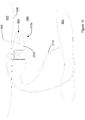
- FIG. 1 shows example of anchors 1800 that may be employed within the present teaching.
- These anchors are desirably formed of a bio-absorbable material such that they can be left within the body post-surgery.
- the anchors comprise a head portion 1810 and a suture coupling portion 1820 at opposing ends of the anchor.
- Two or more barbs 1830 are also provided.
- the barbs are at least partially flexible and are orientated that in the absence of an applied force thereon will extend outwardly from the head 1810.
- the barbs 1830 When being driven through a needle channel or the abdominal wall itself, the barbs 1830 are displaced inwardly to be substantially parallel with the major longitudinal axis of the anchor- that axis extending from the head 1810 to the suture coupling portion 1820.
- head portion 1810 is illustrated here with a radiused tip, this is not intended to be limiting, as the head portion may feature any number of needle tip configurations.
- the suture/anchor assembly may consist of a length of bioabsorbable suture attached to bioabsorbable anchor, provided for example in the form of a length of bioabsorbable tubing, and in one embodiment configured such that the assembly is t-shaped.
- the suture may be a braided suture made from a bioabsorbable polymer such as PGA for example.
- PGA bioabsorbable polymer
- the anchor may be deployed using a driver (not shown).
- the driver will typically engage with or couple to the suture coupling portion 1820.
- the driver comprises a hollow drive tip which is receivable onto the suture coupling portion 1820- the suture coupling portion being at least partially received into the hollow tip.
- the mating of the anchor with the driver provides an integrated anchor delivery tool where the head 1810 of the anchor is used to pierce the abdominal wall upon application of a force using the driver.
- the barbs may retract to align along an outer surface of the driver during delivery.
- the suture 1350 may be passed internally within the driver- requiring the body of the driver to be substantially hollow. In another configuration the suture will pass along the outer surface of the driver.
- the anchor of Figure 1 is suspended at one end of the anchor from the suture 1350 so that it hangs vertically from the suture.
- suture is coupled to the anchor in a way that causes the anchor to extend laterally or horizontally from the suture.
- Such a configuration effectively provides a T-bar arrangement whereby the suture forms the body of the T and the anchor the horizontal member that is coupled to the body. Examples of such an arrangement will be described with reference to Figure 2 .
- Such an arrangement may be deployed using a braided suture which has the advantage of securely holding a knot and is well suited to the construction method illustrated in 2A and 2B.
- the anchor 2103 is formed from a short length of PGLA tubing and has a hole 2102 made in its side wall.
- the suture 2101 is threaded through this hole and knotted with a constrictor knot such as a double overhand knot.
- the knot is then pulled back into the main lumen of the tubing, the knot being too large to come through the hole 2102 on the side wall.
- a double overhand knot is used in this embodiment the disclosure of such is not intended to limit the type of knot used.
- braided suture is not as prone to taking a shape set when wound tightly on a spool as monofilament is, making braided suture a preferred option on devices which entail the suture being wound on a spool.
- a monofilament suture could be used.
- Polydioxanone (PDS) and Poly(glycolideco-caprolactone) (Poliglecaprone 25) are examples of such materials.
- a disadvantage of monofilament suture is its reduced knot strength when compared to a comparably sized braided suture.
- An assembly employing monofilament suture may include a larger diameter suture, or be crimped into the anchor if the anchor is a stainless steel option.
- suture is attached to a bioabsorbable anchor
- Another option would be to place multiple barbs on the suture so that the suture itself acts as an anchor. An example of such suture will be described later.
- the anchor in this configuration consists of an extruded tube.
- the hole in the side wall is sized to suit the suture diameter and may be disposed at the centre of the extruded length.
- the tubing material in an exemplary arrangement is Poly(L-lactide-co-glycolide) (PLGA) but could be made from any ratios of the following materials Poly(L-lactide-co-glycolide) (PLGA), Polylactic acid (PLA), Polyglycolide (PGA), Polydioxanone (PDS), Polycaprolactone (PCL).
- the sutures and anchors may be composed of a fast degrading polymer.
- the sutures and anchors may be composed of a slow degrading polymer.
- the anchors may have an additional coating of Polylactic acid (PLA) or Polycaprolactone (PCL) or a copolymer blend of these polymers in order to vary the degradation profile.
- PLA Polylactic acid
- PCL Polycaprolactone
- the degree of crystallisation of the polymer composition of the anchors may be altered through heating and cooling treatments to change its mechanical properties.
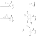
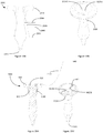
- FIG. 2 shows various examples of anchors that may be deployed in accordance with the present teaching.
- a suture 2101 is passed through an aperture 2102 in the body of the anchor 2103.
- a knot 2104 may then be tied to retain the suture relative to the anchor.
- the anchor body 2103 is desirably hollow to allow both for location of the knot within the body, but also to allow for engagement of a driver with the anchor to enable its presentation through the abdominal wall into the abdominal cavity.
- a front end or leading surface 2105 is chamfered or otherwise sharpened to provide a driving surface to facilitate the passage through the abdominal wall.
- the back end or trailing surface 2106 is desirably the end that engages with the driver, not shown.
- an additional aperture may be provided in the body of the anchor whereby suture may be reintroduced into the anchor body and then travel out of the back end 2106 of the anchor.
- Such an implementation would be particularly useful in combination with a hollow driver whereby the suture could then pass directly into the driver. This could be particularly useful in the context of use of barbed suture where there is a desire to minimise the exposure of the barbs to the tissue until such time as deployment is required.
- Figure 2C shows an alternative coupling arrangement for facilitating tethering of the anchor to suture.
- the suture passes through the body 2107 of the anchor- first and second apertures are provided to facilitate this passage.
- On threading the suture through the body it may then be tied against itself to retain the anchor within a loop.
- First and second anchors could be retained against one another by passing a first anchor through the loop formed for the second.
- the body of the anchor is solid, but this is not intended to be limiting.
- Figures 2D and 2E shows a further arrangement whereby suture 2101 is tied around an outer surface of an anchor 2100 in a knot 2108.
- the knot when formed has a knot tail.
- This tail desirably has a length sufficient that when tension is applied to the knot, the knot will constrict on itself prior to pulling the tail through the knot and effecting an opening of the knot.
- Suitable lengths of the tail are those that are related to the diameter of the suture that is used. Typical dimensions of suture are 0.25 mm and the knot tail is formed with a length of at least 2.5 mm. In accordance with the present teaching knot tails of a length at least 10-40 times the diameter of the suture used are desirable.
- the knot is located within a recessed portion 2109 of the outer body of the anchor. In this way the physical formation of the knot does not project substantially beyond the major surface 2110 of the anchor. It will be understood that the anchor is delivered in direction that is substantially parallel to the major axis of the body and that the recessed portion prevents lateral movement of the knot as it is driven through tissue.
- the anchor could alternatively, or additionally, comprise a textured surface which would restrict relative movement of the knot to the anchor.
- the location of the knot 2108 to the anchor may be more closely secured by provision of a second knot 2111 below the anchor. Further securing could be facilitated by a third knot 2112 above the anchor such as shown in Figure 2G .
- a heat formed flat 2114 provided such as the example of Figure 2H .
- the end of the suture could be heat stamped. It will be appreciated that heat forming a braided material in this fashion will produce a flared end to the suture, which could be usefully employed to prevent the end of the suture pulling through the knot.
- the knot or a portion of the knot could be dipped or coated in liquid bioabsorbable polymer for example polyglycolide, poly(d-lactide), poly(l-lactide), poly(dl-lactide), polycaprolactone or copolymers of those listed.
- the end of the suture could be dipped to form a stiff portion in a similar manner to an aglet on a shoe lace, which would prevent this portion form being pulled into the knot when tension is applied to the suture, avoiding knot failure.
- FIGS 2D-2H illustrate exemplary assemblies where the suture is attached to the anchor with a constrictor knot. It will be appreciated however, that other knots could be usefully employed to achieve a similar result, examples of which would be a boa knot, double overhand, strangle knot or double constrictor. This list is not intended to be limiting and the selection of knot is based on end requirements like knot security and knot profile.
- the knot of Figures 2D-2E may be further secured by pre-tensioning the knot. This may be achieved by making the knot, securing one end of the suture, and to the other end applying a weight.
- the weight used could be in the range 0.5kg - 2kg, and more specifically 1kg for the illustrated embodiment. This range is not intended to be limiting as a number of factors influence knot security, for example the suture material, braid construction, knot selection or the presence of adjacent knots or flats as illustrated in Figures 2F-H .
- the anchor is substantially hollow so as to allow presentation of a driver into an inner volume of the anchor.
- the anchor will be arranged collinearly with the longitudinal axis of the driver such that a presentation of the driver through the abdominal wall- or a guide channel provided in a cooperating device- will direct the anchor in the same direction as the leading end of the driver.
- the driver may extend through the anchor, in which case the driver will have a piercing leading surface that will extend beyond the body of the anchor and which on delivery of the anchor to the abdominal cavity can be withdrawn from the anchor, leaving the anchor in situ.
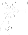
- FIG 3 shows how a driver 2200 may engage with an anchor 2100- such as the examples of Figure 2 and then drive the anchor forwardly.
- the driver 2200 engages with an end surface of the anchor. Pushing the driver forwardly effects a corresponding movement of the anchor through and into the abdominal cavity.
- the driver has a main body portion 2202 and a tapered end portion 2203.
- the tapered end portion 2203 has a smaller cross sectional diameter than the body portion 2202. In this way when the tapered end portion 2203 is presented into and engages with the end 2106 of the anchor, a step 2204 is formed. This step provides an abutment surface.
- the abutment surface of the step 2204 will engage with or contact against the abdominal wall. This will create a resistance which facilitates the removal of the driver from the anchor.
- the outer diameter of the end portion 2106 in the region of the step is greater than the diameter of the tapered end portion 2203. It may extend to have a diameter as great as the diameter of the body portion 2202 of the driver.
- the driver projects through the anchor such that the anchor is located on the driver between the driver needle end portion 2205 and the main body 2202.
- the needle end portion is desirably sharpened to allow a piercing of the abdominal wall as necessary.
- the length of the needle end portion and geometry may vary- as shown in the examples of Figures 3A and 3B .
- the end surface 2100 of the anchor may also include a chamfered outer surface 2207 which also facilitates the presentation of the anchor through the abdominal wall. It will be appreciated that as the driver is presented through the abdominal wall, the pressure on the leading surface 2207 will increase and will push the anchor towards the head of the driver, until such time as the inner diameter of the anchor is greater than the outer diameter of the driver, at which time movement rearwardly of the anchor is prevented.
- FIG. 4 shows another example of an anchor and driver arrangement.
- an anchor is located on a driver which is used to deliver the anchor within the abdominal cavity.
- the needle end portion 2205 is not provided with a continuous tapered outer surface but rather is configured in a two part construct with a tip 400 being provided at the very end of the driver.
- the tip advantageously allows the anchor to be positioned on the non-tip portion such that the needle portion is never within the lumen of the anchor. In that scenario there would be an opportunity for tissue to lodge at the tip of the anchor and prevent accurate deployment of the anchor.
- This arrangement of driver differs from that previously described in that it includes a cleat 405 or other securement feature.
- the cleat is integrally formed in a head portion 410 of the driver. This is advantageous in that it allows the suture 2101 to be maintained in location along the body of the driver. It also ensures that an end portion of the suture is accessible subsequent to delivery of the anchor into the abdominal cavity. It will be appreciated that the actual location or form of the securement feature may vary.
- the suture may be wrapped around the head portion a number of times to attain greater security. In this embodiment, premature anchor deployment is prevented while the suture removal process remains the same in that the user pulls the suture vertically to release.
- the head portion 410 also includes a textured outer surface 415 which provides improved grip to the user of the driver. This may be formed in a variety of different ways such as overmoulding an elastomeric material onto the body of the driver.
- FIG. 5 shows another example of a driver which again uses the same reference numerals for parts previously described.
- a bulbous head portion 500 is provided.
- This is another grip configuration that may be advantageously employed within the context of the present teaching.
- Such a bulbous head allows location of the driver securely into a user's palm and increases the amount of actual force that may be used in delivery of the anchor through the abdominal wall. Such an arrangement is particularly advantageous in scenarios where the driver is used by itself to effect presentation of the anchor through the abdominal wall.
- the present teaching provides a driver with an integrated guide indicator.
- An example of such an arrangement is shown in an upper surface 505 of the bulbous head 500.
- a visual indicator 510 is provided.
- This configuration of the visual window employs three windows- although of course it will be appreciated that the dimensions or numbers of such windows may vary.
- the windows are colour coded and dependent on the orientation of the driver relative to the desired orientation one of the windows may be preferentially illuminated.
- the driver may include an angular orientation sensor implemented in the form for example of an accelerometer or gyroscope, which will provide an output of the angular orientation of the driver relative to a predetermined plane.
- the driver may be pre-calibrated, or the surgeon may be able to calibrate the driver himself, as to a correct presentation angle.
- the window will show a first colour, for example green.
- a second colour for example orange may be displayed. This will prompt the surgeon to modify the angle of presentation until the green is again shown.
- a different colour, for example red may be shown. This may prompt the surgeon to withdraw and retry.
- the visual indicators of green, orange and red are exemplary of the type of visual indicator that may be deployed.
- the driver may include an audible warning generator which will be similarly activated dependent on the orientation of the driver relative to a desired preselected orientation.
- the necessary hardware and or software necessary to implement such an angular indicator may be located within the bulbous head of the driver.
- the driver is used to directly pass the anchor through the abdominal wall it is preferable that the driver has a degree of rigidity such that it will not flex during the presentation to and through the abdominal wall.
- the driver may be necessary for all or part of the driver body to have a degree of resilience or flex to allow it adopt to the contours of the guide channel.
- These two forms of driver may be collectively known as rigid or flexible drivers and within the context of the present teaching it is not intended to limit to any one form of driver- except as may be deemed necessary in light of a specific application of use.
- Figure 6 and Figure 7 show an example of a guide tool, or simply a guide, that may be used in combination with the driver/anchor arrangement heretofore described.
- a guide 600 is provided.
- the guide is configured to define a driver guide channel located between an inlet 620 and outlet 625 defined within the body of the guide 600.
- the body is provided in a telescopic arrangement comprising first 605, second 610 and third 615 parts. It will be appreciated that the number and dimensions of these parts may vary dependent on the actual implementation.
- the telescopic arrangement facilitates different defect or trocar lengths.
- the guide tool is co-operable with the driver and anchor.
- the at least one driver guide channel is dimensioned for accommodating the driver and anchor.
- the tool otherwise has dimensions insufficient to accommodate other surgical equipment. In this way it is different from other laparoscopic surgical equipment which may have had a dual functionality; that of providing an access port for delivery of surgical equipment into the abdominal cavity and also driver guide channels for separate delivery of suture.
- the guide tool is a dedicated sole purpose guide which allows for the delivery of suture into or through an abdominal wall.
- a flange 630 is provided between the inlet 620 and outlet 625.
- the flange 630 provides a collar which has a larger diameter than the body of the guide 600.
- the guide body 600 will be presented through a cut formed in the abdominal wall and will pass through that cut until the collar abuts against the outer part of the fascial layer.
- the collar provides a locator to assist the surgeon in ensuring the relative location of the outlet 625.
- the driver with attached anchor may then be presented through the inlet which is located outside the body and will pass out the outlet into the abdominal wall. It will be appreciated that in certain configurations the inlet and outlet will be on the same side of the guide 600. This will require the driver to have degree of flexibility sufficient to allow it to deform to the curved channel formed between the inlet and outlet.
- the inlet and outlet are on opposing sides of the guide 600 such that a rigid driver may be presented through the inlet and along a substantially straight channel before exiting the outlet.
- two inlets and two outlets may be provided but it will be appreciated that the present teaching is not intended to be restricted to any specific number of inlets or outlets.
- the user could then rotate the device to allow use of the same inlets and outlets in another location.
- multiple inlets and outlets could be used.
- a single inlet could be in communication with a plurality of outlets.
- Figure 7 shows another example of a guide 700 which differs in that a flange 730 is located in a lower portion of the guide 700.
- the guide has a leading end 705 and a trailing end 710.
- the flange is desirably flexible such that when the guide is being presented through the abdominal wall the flange will flex rearwardly away from the leading end 705 and attempt to conform with the contours of the body of the guide 700. To facilitate this conformity of the flange and ensure that it does not project substantially beyond the body surface during passage through the abdominal wall, it may be preferable not to form the flange as a continuous piece.
- the flange is formed from two portions 731, 732 which are located on either side of the flange body.
- the flange portions 731, 732 will deform in the direction shown by the arrow so as to attempt to be parallel with the major axis of the body 700.
- the flange portions On receipt within the abdominal cavity, there is no biasing force on the flange with the result that the flange portions will return to their normal position, which is substantially perpendicular to the body- the position shown in Figure 7 .
- the open flange will contact against an inner surface of the abdominal wall giving the surgeon tactile feedback as to the location of the guide.
- This guide 700 also includes an inlet 725 and outlet 726.
- the inlet will, similarly to Figure 6 , be located outside the body and allows for the presentation of a driver into the guide.
- the driver and its associated anchor will then travel out of the outlet and into the abdominal wall. Further application of pressure onto the driver will cause the driver and anchor to pass into the abdominal cavity. Retraction of the driver will then release the anchor from the driver and the application of tension onto the suture will increase the tension applied onto the anchor and bring it into contact with an inner surface of the abdominal wall.
- use of an anchor and guide/driver combination may be used to deliver two or more anchors. This may be usefully employed in circumstances where two or more anchors are required to effect closure of larger wound sites. For example three anchors could be deployed in a triangular configuration or four anchors in an X configuration could be deployed using the present teaching,
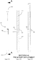
- Figure 8A shows the guide of Figure 7 including a section line A-A.
- Figure 8B and 8C show two alternatives of guide channels that could be formed within the body of the guide.
- a driver will enter a guide channel 800 on a first side of the body and then exit from a second side- shown in the two examples of a solid and dash line. Effectively first and second guide channels are provided. This arrangement is particularly usefully deployed in conjunction with a rigid driver as the channel 800 is substantially straight. The angle of the channel will determine the angle of presentation of the driver and associated anchor into the abdominal wall.
- the driver will enter and exit a guide channel 810 on the same side of the body.
- First and second channels 810 are provided on either side of the body and the driver will require a degree of flexibility to allow it to adopt to the curved contour of the channel 810.
- the driver will exit via the exit port 726 at an angle determined by the deflection surface 815 provided proximal to the exit 726.
- Figure 8D shows yet a further example which is not based on the configuration of Figure 7 .
- the entry ports are in the top of the body such that the driver will be presented coaxially with the major axis of the guide prior to being deflected outwardly by a deflection surface 815 provided proximal to the exit port 726.
- the guide shown in Figures 6 to 8 may include an insufflation port which may be usefully employed in maintaining pneumoperitoneum during surgical procedures.
- Figures 9 , 10 and 11 show examples of how an anchor in accordance with the present teaching may be used to assist in the moving of internal organs to allow a surgeon access to a surgical site.
- the schematics of these Figures illustrate the scenario where the anchor has already been deployed into the abdominal cavity.
- the void 900 represents the abdominal cavity and the abdominal wall 910 is located above same.
- a representative organ- the small bowel 920 - is shown as an example of the type of organ that may require movement to allow surgical access to a site otherwise occluded by its normal location.
- an anchor 2100 is secured to suture 2101 using a knot 2108- similarly to that described before.
- Suture is passed through the abdominal wall- such as using the technique that will be described below with reference to Figure 11 - and then looped around the organ to be moved.
- the suture may then be retained in the anchor using a cleat or other securement feature 925.
- the tensioning of the anchor against the abdominal wall 910 is achieved by tightening the suture until such time as the anchor 2100 is brought into contact with an inner surface 930 of the abdominal wall.
- a free end 935 of the suture may then be passed around the organ 920 and pulled so as to move the organ to a desired location.
- the securement of the suture within the cleat 925 maintains that desired location until such time as the surgical requirement for the movement of the organ is dispensed with, at which time the release of the suture from the cleat will allow the organ return to its normal location.
- the cleat is provided or formed in the back end 2106 of the anchor.
- the cleat is formed by a cut 926 in the back end that extends from the step 2204 back to an eye 927.
- the suture may be passed through the eye- which defines an opening in the body of the anchor sufficiently large for the suture to pass- and then locked in the cut 926 where it is retained.
- the cleat is formed in the front end 2207 of the anchor 2100.
- the free end 935 of the suture is passed through the back of the anchor and through the body of the anchor where it is then secured in the cleat.
- Such an arrangement is advantageous as the suture cleat is adjacent to the suture and is provided in the form of a tapered slot which may provide a more secure attachment to that of Figure 9 and thereby may be usefully employed for heavier organs.
- FIG 11 shows an example of how the suture shown in the abdominal wall of Figures 9 and 10 can be located.
- a tissue grasper 1100 which comprises two opposing arms 1105, 1106 which are moveable relative to one another is used to grasp a portion of the abdominal wall 910.
- Each of the arms include a window 1110 through which an anchor 2100 deployed on a driver 2200 may be presented.
- the anchor will therefore pass through the portion of the abdominal wall retained within the tissue grasper arms, and will bring its associated suture 2101 with it. Once through both surfaces a retraction of the driver will displace the anchor from the driver and allow for the subsequent looping of the suture about the tissue or organ that requires movement.
- the grasper 1100 and driver 2200 may be activated externally of the abdominal cavity during laparoscopic surgeries.
- each of the anchor and driver may be configured to allow the suture to pass internally from the anchor through the body of the driver. The suture will then exit the driver from an exit port which is operably located externally of the body. Such an arrangement advantageously allows the surgeon to visualise the deployment of the suture and anchor as it is easier to see the suture passing relative to the exit port of the driver.
- the anchor and driver are co-operable with a guide shaft 1200.
- the guide shaft 1200 is desirably provided with a tapered or sharpened leading edge.
- the guide shaft may be used for transporting the anchor 2100 through the abdominal wall into the abdominal cavity- the anchor being located within the guide shaft during this passage.
- the anchor 2100 On passage of the leading edge 1205 into the abdominal cavity, the anchor 2100 may then be biased out of the guide shaft using a driver 1210.
- driver and anchor in these configurations do not have to come into contact with the abdominal wall during the transit of the anchor into the abdominal cavity, their shapes and configurations do not have to be contoured to facilitate such passage.
- Figure 12D also shows a variant in coupling of the suture to the anchor whereby a knot is located within the anchor as opposed to tied on the outer surface- such as Figures 12A to 12C .
- This arrangement of Figure 12D is similar in construct to that described with reference to Figure 2A and 2B .
- Figure 12E shows another variant whereby the driver is configured to receive suture within the body of the driver. In this way the suture is retained within the driver until such time as the driver is withdrawn from the surgical site, at which time the suture will be drawn out from the driver.
- the guide of Figure 12 may be used independently of another guide, it is also possible to deploy the guide in conjunction with one or more of the guides described above with reference to Figure 8 .
- the anchor and driver are provided within a guide such as that shown in Figure 12 .
- a guide such as that shown in Figure 8 is then deployed into the abdominal incision and provides a channel for delivery of the Figure 12 guide to allow deployment of the anchor.
- the guide shaft of Figure 12 may also incorporate a flange or collar such as that described with reference to Figure 7 , which will assist the surgeon in determination when the guide shaft has pierced the abdominal wall and is in location for delivery of the anchor into the abdominal cavity. On location the anchor can be biased out of the guide shaft using an application of pressure via the driver 1210.
- the length of travel of the driver 1210 within the guide shaft may be limited so as to control how far the anchor is pushed relative to the end of the guide shaft.
- Such control is particularly advantageous in deployment of barbed suture such as that shown in Figure 12B .
- a plurality of barbs 1215 are integrated onto the suture- examples include unidirectional and bidirectional barbs. As the barbs will naturally engage with the tissue that they contact it is important to control their deployment.
- the barbed suture may be contained within the guide shaft until such time as it is needed. The deployment may then be controlled.
- the anchor and driver have been referenced with regard to a single deployment configuration. Effectively one anchor is provided onto the driver and then located as appropriate.
- the anchor is provided with a length of suture that can then be used to effect a closure of a wound or to provide an anchoring arrangement.
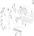
- Figure 13 shows a modification where there is a desire to retain or anchor a web, mesh, or organ at a plurality of locations.
- the illustrated exemplary scenario is a desired retention of a web 1310 against the abdominal wall 1320.
- the web 1310 has an extended surface area and therefore requires retention at a plurality of locations.
- an anchor/driver combination In this configuration an anchor 1330 is, similarly to that described before such as with reference to Figure 2 , coupled at a mid-point thereof to suture 1340.
- suture is a preferred coupling mechanism but other couplers could also be considered and usefully employed.
- the anchor will hang vertically from the suture in an inverted T configuration - particularly if the point of coupling is the centre of gravity or center of mass of the anchor.
- the anchor comprises first and second elements.
- the first element or main anchor body 1331 is similar to that described already.
- a second element, the anchor head 1332 is also coupled to suture but is coupled at the other end of the suture to the anchor body. In this way the suture 1340 separates the anchor head 1332 from the anchor body 1331.
- the driver 1315 is configured to engage with the anchor and to achieve a driving of the anchor to a desired location.
- the driver comprises a socket 1316 provided in a leading end 1317 of the driver.
- This leading end 1317 may be sharpened or otherwise optimised to allow an at least partial penetration of the leading end of the driver into the abdominal wall or other organ as desired.
- the anchor head 1332 is seatable in the socket 1316 and when seated, movement of the driver will effect a corresponding movement of the anchor 1330.
- the driver will operably effect a driving of the anchor head into the abdominal wall 1320.
- the length of the suture 1340 - or other coupling member- separating the anchor head from the anchor body is desirably such that the length of travel of the driver into the abdominal wall is greater than the length of the suture. In this way when the driver effects a driving of the anchor into the abdominal wall, the anchor head will be driven into the actual abdominal wall whereas the anchor body 1331 which is trailing on the suture behind the anchor head 1332 will not travel into the abdominal wall.
- a compressive force is then applied between the delivered anchor head 1332 and the anchor body 1331 and this will achieve retention of the anchor against the abdominal wall.
- judiciously targeting the point of delivery of the anchor head it is possible to locate a web or other material/device that requires anchoring between the anchor head and anchor body. In this way a located anchor serves to retain the web or other material/device in situ. Where one or more elements of this anchor are formed from bioabsorable materials these can be left in situ until such time as they dissolve.
- Such anchors can be used independently of other aspects of the present teaching as described herein.
- one anchor may be sufficient.
- multiple anchors may be required.
- the anchor 1330 and driver 1315 may be provided in a gun configuration 1300 whereby a plurality of anchors may be sequentially used in conjunction with the same driver 1315. By bringing a succession of anchors into contact with the same driver it is possible to use that driver to locate, in a sequential fashion, a plurality of anchors which may be spring loaded in position or ratcheted into position.
- the anchor and driver are located within the volume defined by a guide 1350.
- the guide comprises first 1351 and second 1352 walls and each of the anchors 1320 and driver 1315 are moveable relative to the walls of the guide.
- a plurality of anchors are stacked or stackable in the guide.
- the anchors are desirably stacked such that the anchor head 1332 is located above the anchor body 1331.
- the orientation of the anchor body is desirably such that its major axis is parallel with the major axis of the guide.
- the head 1332 typically rests on a side surface of the anchor body 1331.
- the driver is moveable between a resting and active position.
- the socket 1316 In the resting position the socket 1316 is provided proximal to a head of a neighbouring anchor.
- the head 1332 may be displaced onto the socket 1316 by action of a pivotable actuator 1360 on the head 1332. This will typically be achieved by a triggering action effected by a user.
- the actuator 1360 comprises a chamfered surface 1361 which will, on movement of the actuator, displace the head 1332 into the path of the driver- where it is received and seated within the socket 1316.
- a second triggering action by the user will effect a movement of the driver out of the guide 1350.
- the movement of a first anchor out of the guide will desirably effect a corresponding movement of the next anchor in line towards the mouth of the guide. In this way when the driver returns to its resting position, there is another anchor awaiting deployment within the gun.
- anchor heads may vary dependent on the application.
- anchor heads are shown being a sphere, a tetrahedron, a cube and a dodecahedron but it will be appreciated that other configurations may also usefully be employed.
- the anchor heads can be provided as a molded part as could the suture element. In other configurations the anchor head could be formed from a knot formed in the suture or other material.
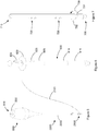
- FIG 14A shows another example of a guide which may be used with a driver and anchors like those illustrated in Figure 4 .
- a guide of this design is used by removing the Trocar 2400 shown in Figure 14B .
- the suture guide is positioned in the defect and a driver 2300 is used deliver an anchor 2100 though a guide channel 800 defined within the guide. This process is repeated through a second guide channel.
- the suture 2101 at the proximal end of the anchor in Figure 14D is pulled by the surgeon to approximate the defect and tied with a knot as illustrated in Figure 14E .
- the guide illustrated in Figure 14A features a tapered leading portion 2580.
- tissue will tend to contact against the tapered portion of the suture guide.
- the fascial recruitment will increase as the abdominal thickness increases. This may be disadvantageous as a larger fascial recruitment can lead to an increased likelihood of capturing nerves, leading to post operative pain.
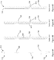
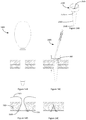
- a guide such as that shown in Figure 15 may be provided, In such a configuration, a portion of the shaft 2690 of the guide tapers as the depth increases within the specified target abdominal wall thickness 2995. This profile enables a relatively uniform fascial recruitment to be achieved across the target abdominal wall thickness.
- Figure 18 shows a guide which has a more exaggerated shaft geometry than that of Figure 15 .
- Figure 18A illustrates how using such a geometry it is possible to achieve a consistent bite in the target abdominal wall thickness.
- the bite trajectory is illustrated by the line 2992 and the maximum and minimum abdominal wall thickness are represented respectively by lines 2993 and 2994.
- Figure 18 also illustrates a grip 2970 on the head portion which may be advantageously used to aid the user in gripping the device while inserting it into a defect.
- the guides of Figures 15 and 18 features a narrow tip 2695 preceded by a larger diameter section which centres the device during delivery and aids navigation through tissue layers.
- the guide of Figures 15 and 18 also features a tapered portion 2991, between the head portion and the shaft which facilitates sealing larger port sites.
- the device could include an exchangeable central core, not shown.
- This central core could form the tip portion 2695 and be substantially longer than the device of Figure 15A .
- This core could be passed through a trocar, and the trocar then exchanged, leaving the core in situ in the defect.
- This core would then act as a guide rail for the device similar to that of Figure 15A , but having a hollow channel though its centreline, slightly larger than the diameter of the core rod. This would be advantageous in a thicker abdominal wall, allowing for easier placement of the guide.
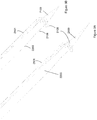
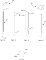
- Figure 16A shows a further embodiment of a guide.
- the guide comprises a shaft 650 having a constant diameter along its length.
- Figure 17 illustrates a guide rod.
- the guide rod 600 will be provided with a separate co operable sleeve 640.
- the guide rod has a deformable rectangular profile 2830 at its distal end. This portion could be configured to provide more resistance on removal than entry.
- the user would insert the guide rod through a trocar.
- the deformable rectangular profile would bend towards the proximal end of the guide rod as the guide rod is advanced through the trocar. Once the deformable portion exits the trocar inside the abdominal space the deformable portion adopts a t-bar configuration. The trocar is then removed.
- the guide rod can be positioned against the inner abdominal wall using a laparoscopic camera, or by relying on the tactile feedback of the deformable portion coming in contact with the inner abdominal wall.
- the sleeve 640 can then be passed over the proximal end 2810 of the guide rod and can be used to provide an airtight seal around the defect, and has the advantage of allowing the guide rod to be useable with a greater range of trocar sizes as the under surface 641 of the sleeve tapers from the guide rod diameter to a substantially larger diameter.
- the sleeve features an upper portion 642 which can be pressed by the user when the anchors are being deployed to stabilise the guide rod, ensuring a good vertical orientation of the rod relative to the abdominal wall.
- a driver and anchor such as that shown in Figure 4 , could then be used to deliver the anchor through firstly the first driver channel 2825A and secondly through the second driver channel 2825B.
- a pair of anchors are left in the defect as illustrated in Figure 14D and the defect can then be closed as illustrated in Figure 14E .
- the deformable portion could be formed from a shape memory material such as that provided in the form of a flat Nitinol wire.
- the Nitinol wire could be passed through a slot in the guide rod and held in place by an interference fit. More ideally a screw could be used to secure the Nitinol. A hole for the screw could be left in the leading edge portion 2805 and provided so as to be substantially parallel to the major axis of the rod. To provide additional securement the Nitinol may have a hole at its centre with which the screw engages.
- the slot through which the Nitinol passes is illustrated as being substantially perpendicular to the major axis of the guide rod.
- This channel could be curved to bias the Nitinol in a given direction, or a dowel could be used to bias the Nitinol.
- a more cost effective version of the device could be manufactured from a plastic extrusion, preferably in a rectangular shape.
- the guide of Figure 19 is similar to those described as Figures 15 and 18 , but has two additional features.
- the first is a change to the driver channel.
- the initial portion of the driver channel 820 is of reduced diameter.
- the driver channel diameter is governed by the diameter of the anchor which has a larger diameter than the driver. By reducing the diameter of this portion the driver has less play room in the device, which should result in more accurate delivery.
- the guide illustrated also features a larger diameter portion 830 to the driver channel. This portion can be utilised to receive anchors which are pre-loaded as illustrated in Figure 19A .
- a second feature is the inclusion of a suture retention cleat 406. This cleat can be used to hold the preloaded anchors in place by pulling the suture taut and placing the suture in the cleats as illustrated in Figure 19A .
- Figure 20 illustrates another arrangement of guide rod system.
- the guide rod features a pair of wings which are biased outwards 3130, see Figure 20D .
- the wings are maintained against the guide rod shaft by a sleeve 645.
- the sleeve features a window 646.
- this window is pushed forward, allowing the wings to deploy and form an inner abdominal wall engaging surface. The user will pull the device back until the inner abdominal wall engaging surface engages the inner abdominal wall.
- This activation method may also be used with the configuration shown in Figure 17 .
- a driver and anchor of Figure 4 could then be used to deliver the anchor through firstly the first driver channel 2125A and secondly through the second driver channel 2125B.
- the sleeve When the sleeve is retracted the edge at the distal end of the window 647 engages with the wings and forces them back into a non deployed configuration. This allows the guide rod to be removed, and upon removal a pair of anchors is left in the defect as illustrated in Figure 14D and the defect can then be closed as illustrated in Figure 14E .
- Figure 21 show a further embodiment of guide rod whereby the wings 3230 are formed from two Nitinol wires 3231 Aand 3231 B.
- the Nitinol wires are in a channel in the main shaft 3232 of the guide rod.
- the Nitinol wires are joined to a pusher 3233. When this pusher is advanced the Nitinol wires are pushed out of the channel creating a wing feature as illustrated in Figure 21C .
- the device can then be used in a similar fashion to that described for the device of Figure 20 .
- Figure 22 shows another embodiment of a guide rod.
- a pair of guide channels 800 are formed in the outer portion of the guide rod 600.
- Removal of the inner shaft 3333 causes the tapered surface 3334 to engage with the inner surface of the guide channel which causes the guide channel to move laterally towards a deployed configuration once the constant diameter portion 3335 of the inner shaft comes in contact with the inner surface of the guide channels.
- the inner shaft could feature a range of constant diameter sections joined by tapering sections, This would allow the guide channels to be deployed to accommodate different diameter port sizes.
- a polymeric sleeve could be added to cover the guide channel portion of the guide rod, which would further increase the perimeter for use in larger defects.
- Figure 23A illustrates an isometric view of a guide rod which facilitates delivery of an guide 3900.
- a spline 3450 is cut from the rod. This spline corresponds to the geometry of the guide 3900, which is shown over the rod in Figure 1A .
- the rod could be placed in the defect after the trocar is removed, or the shaft could be optimally designed to exchange through a trocar, which would advantageously maintain pneumoperitonium.
- Figure 23B shows the guide 3900 interacting with the spline channel, with the guide 3900 advanced even further in Figure 23C .
- the guide 3900 could be removed and placed in a similar recess on the opposite side of the rod to facilitate delivery of the guide 3900 on the second side of the defect.
- round portion 3420 of the rod distal to the spline shaft is crucial to maintaining pneumoperitonium as the spline channels would present a escapement route for air.
- This round shaft portion could be extended in length as illustrated by 3520 in Figure 24A .
- the images presented here are not intended to be limiting.
- An additional feature which may be included, but is not illustrated, is a ratchet type of mechanism, or a catch which could hold the guide 3900 in position, once it is at the desired location.
- this type of rod could be usefully employed to facilitate delivery of a guide 3950 as illustrated in Figure 23D .
- a similar method of deployment could be achieved with a simple port exchange rod such as that provided by the Conmed Corporation under the trade name Port Saver® ghostStick.
- Figure 24A and 24B show a further modification of the device illustrated in Figure 23A .
- the spline 3550 is sized such that the guide 3900 does not protrude past the outer diameter of the rod when it is presented into the spline channel of the rod, Figure 24A .
- the spline channel would be parallel 3560 with the rod for the majority of its travel. Towards the end of the travel the channel tapers outward 3570 to deploy the guide 3900 for use, as shown in Figures 24B and 24C .
- a marker, not shown, on the shaft could be placed slightly above the point at which guide 3900 protrudes past the rod diameter.
- this marker could be coincident with the skin, ensuring that the guide 3900 is deployed below the skin, allowing for use in tighter skin incisions.
- This marker could be a line or band on the rod, or it could be formed by an elastomeric tube portion which could cover the distal portion of the rod.
- An advantage of use of an elastomeric portion is that it would increase the overall diameter of the rod portion within the defect, preventing unwanted loss of pneumoperitonium and enabling compatibility with larger defects.
- Figure 25A to 25B show a further embodiment, whereby the spline 3650 channel guides the guide 3900 through the rod where the guide 3900 exits the side of rod at a level below the skin 3680.
- the guide 3900 when the guide 3900 is in the first part of the guide channel, its largest profile is equal to that of the rod, allowing the profile to pass through the skin line.
- the guide 3900 When advanced below the skin the guide 3900 is then guided outwards by the tapering out 3670 of the guide channels, though the side wall of the rod.
- the guide 3900 at this point is adjacent to the outer diameter of the rod, which maximises the fascial recruitment obtained by the driver and anchor when passed through the guide.
- Figure 26 shows a further embodiment of the guide of Figures 15 and 18 .
- the guide illustrated here features a series of indentations 3770 arranged circumferentially around the head portion of the guide. These indentations function as grips for the user when handling the head portion, enabling easier rotation of the device in situ. The size and number of such indentations could be varied to improve the grip/fell of the device. It will also be understood that a similar result could be attained by making protrusions on the outer surface.
- the shaft features an increasing shaft diameter portion 3790, as with the guides of Figure 15 and 18 . A disadvantage of the design of Figures 15 and 18 is that the increased diameter portion may make insertion difficult.
- Figure 27 shows an alternate arrangement of the guide from Figure 26 .
- material in removed to leave windows 3810.
- the benefit of such material removal is to significantly reduce moulding times but also allows visibility through the guide.
- the geometry of the guide presented here has been optimised to maintain the strength of the device and minimise air escapement from an insufflated abdomen.
- This device is intended to be a single use device and features a pair of blind holes 3815 arranged opposite to each other.
- the provision of one or more blinds holes such as illustrated may be usefully employed in applications where there is a desire to make the validation of re-sterilisation process difficult.
- This embodiment could be configured reusable by manufacturing it from stainless steel and removing the window portions. Instead, a larger window portion could be provided in a plane perpendicular to the shown windows so that the anchors could be visualised as in this case the guide would not be translucent.
- Figure 27B illustrates the cut out portion of the device which operably is in contact with the tissue adjacent to the driver and anchor trajectory. This surface ensures a consistent bite at increasing depths as illustrated earlier the embodiments of Figures 15 and 18 .
- the profile of the embodiment of Figure 27A features a constant diameter portion 3820 close to the skin surface. This constant diameter portion 3820 desirably provides a surface that is parallel to the major axis of the guide.
- the guide channels 800 are defined within the body of the guide coincident with this constant diameter portion and exit the guide proximal to a lower edge 3820A of the constant diameter portion
- the guide channel comprises exit ports 3826 defined on a cutout portion 3830 below the constant diameter portion 3820.
- the length of the constant diameter portion is selected to be sufficient that when the device is inserted to the head portion 3840, there is no risk of the driver needle catching skin or sub dermis, which is advantageous in producing a more pleasing cosmetic effect.
- Another feature of the guide of Figure 27 is the curved underside surface 3840 of the head portion. This continuously curving portion can be advantageously used to prevent loss of insufflation when the device is placed in ports which are significantly larger than the constant diameter portion 3820. By providing a curved surface which extends upwardly and outwardly from a central axis of the guide, it is possible to present the guide deeper into a wound so as to maintain contact between the guide and the side walls of the wound.
- the cutout portion 3830 defines a concave surface which provides an undercut below the planar surfaces defined by the constant diameter portion.
- the head portion 3800 may define a receiving well 3800A within which suture may be stored prior to deployment. While not shown in Figure 26 , additional storage structures such as spigots or the like about which the suture could be wound may be provided. A lid or cap may be provided on the head portion to cover the receiving well prior to usage of the guide. In this way the suture could be safely retained within the guide until such times as the suture is required for deployment through the guide channels 800.
- a guide provided in accordance with the present teaching may be optimised to have a length greater than the length of the driver that is used with the device.
- the guide provides a stop that prevents the presentation of the driver into the cavity to a depth greater than the length of the guide. This advantageously prevents the tip of the driver inadvertently contacting organs or tissue within the cavity.
- the guide of Figures 26 and 27 feature a leading portion 3880 which is sized to be similar to a human finger.
- This leading portion should optimally have a diameter of between 1 and 2cm.
- the diameter of the device in Figure 27 is sized at 1cm at the leading edge 3881 and tapers up to 1.5cm at the proximal end 3882 of the leading portion which is located about the waist region of the guide, to minimise the profile of the device. This may be especially useful in a scenario where the defect is through a thick abdominal wall where the layers may have shifted laterally after removal of the trocar.
- Devices with narrower tips like the one illustrated in Figure 14A or 18A have a tendency to catch on layers as the device is being placed in the port site making delivery tedious.
- guides such as those described with reference to Figures 26 and 27 allow the deployment of suture on two sides of the guide shaft.
- introduction of suture using such a guide will be monitored by the surgeon using a camera located within the abdominal cavity. It is not unusual in such circumstances for one side of the guide to be occluded from view.
- the present teaching provides, in certain aspects a window, within the guide shaft which allows a user to view through the guide to the other side of the guide. By providing such a window, the surgeon should be able to see the driver being delivered through the device.
- the surgeon may find it easier to tell whether the guide is delivered below the skin surface, as this should be visible through a head portion of the guide,
- a window there are many ways for such a window to be provided, for example it the guide itself could be fabricated from a transparent material. It is not necessary for the entire guide to be formed from such a transparent material and in certain configurations only certain portions of the guide could be formed from such a transparent material.
- the body of the guide could define a window by having a non-solid body form.
- the guide could be fabricated from two or more materials, with a first material being transparent and allow visibility through the guide.
- the exit hole 3826 of the driver channel in the device of Figure 27 is close to approaching the true perimeter of a hole sized for the delivery channel. If we compare this to the exit hole 2526 of Figure 14A or the exit hole 3826 of Figure 26 we can observe that the perimeter of these hole are much greater than the true diameter. This is due to these holes exiting on a surface that is divergent from the channel direction. The disadvantage of such a wide exit hole is that there is greater variance were the path that the driver takes when it exits the guide.
- the device of 27 solves this problem by utilising the proximal cutout portion 3830 to create a surface roughly perpendicular to the driver channel path onto which the hole exits. The advantage of this is that the exit path of the driver is more consistent.
- the device of Figure 27 could be used with a driver and anchor of Figure 4 to close a defect.
- the driver could be used to deliver the anchor through firstly the first driver channel 3825A and secondly through the second driver channel 3825B.
- a pair of anchors are left in the defect as illustrated in Figure 14D and the defect can then be closed as illustrated in Figure 14E .
Landscapes
- Health & Medical Sciences (AREA)
- Life Sciences & Earth Sciences (AREA)
- Surgery (AREA)
- Molecular Biology (AREA)
- Engineering & Computer Science (AREA)
- Biomedical Technology (AREA)
- Heart & Thoracic Surgery (AREA)
- Medical Informatics (AREA)
- Nuclear Medicine, Radiotherapy & Molecular Imaging (AREA)
- Animal Behavior & Ethology (AREA)
- General Health & Medical Sciences (AREA)
- Public Health (AREA)
- Veterinary Medicine (AREA)
- Pathology (AREA)
- Rheumatology (AREA)
- Surgical Instruments (AREA)
Applications Claiming Priority (2)
| Application Number | Priority Date | Filing Date | Title |
|---|---|---|---|
| US13/688,005 US9855031B2 (en) | 2010-04-13 | 2012-11-28 | Suture delivery system |
| PCT/EP2013/073989 WO2014082876A1 (en) | 2012-11-28 | 2013-11-15 | Suture delivery system |
Publications (2)
| Publication Number | Publication Date |
|---|---|
| EP2925236A1 EP2925236A1 (en) | 2015-10-07 |
| EP2925236B1 true EP2925236B1 (en) | 2020-01-22 |
Family
ID=49639860
Family Applications (1)
| Application Number | Title | Priority Date | Filing Date |
|---|---|---|---|
| EP13795203.2A Active EP2925236B1 (en) | 2012-11-28 | 2013-11-15 | Suture delivery system |
Country Status (5)
| Country | Link |
|---|---|
| US (3) | US9855031B2 (enExample) |
| EP (1) | EP2925236B1 (enExample) |
| JP (1) | JP6749098B2 (enExample) |
| AU (1) | AU2013351428A1 (enExample) |
| WO (1) | WO2014082876A1 (enExample) |
Families Citing this family (13)
| Publication number | Priority date | Publication date | Assignee | Title |
|---|---|---|---|---|
| GB2486497B (en) | 2010-12-17 | 2013-06-19 | Neosurgical Ltd | Laparoscopic trocar system |
| US9855031B2 (en) | 2010-04-13 | 2018-01-02 | Neosurgical Limited | Suture delivery system |
| US20150335320A1 (en) * | 2010-04-13 | 2015-11-26 | neoSurgical Ltd. | Suture delivery system |
| WO2014169215A2 (en) * | 2013-04-11 | 2014-10-16 | University Of Utah Research Foundation | Self-closing laparoscopic port |
| JP6402458B2 (ja) * | 2014-03-14 | 2018-10-10 | 住友ベークライト株式会社 | 臓器固定具および臓器固定装置 |
| US11006952B2 (en) | 2016-01-13 | 2021-05-18 | Sharp Fluidics, Llc | Fixation device delivery system |
| US12059148B2 (en) | 2017-06-05 | 2024-08-13 | Conmed Corporation | Suture system and related methods for connecting and creating suspension between at least two bodies |
| EP3801290A4 (en) * | 2018-06-11 | 2022-03-02 | University Of Louisville Research Foundation, Inc. | Trocar site closure clip |
| CN112638283B (zh) * | 2018-07-16 | 2024-02-27 | 乌巴特·奥贾克 | 缝合构件、缝合针和缝合装置 |
| DE202020000044U1 (de) * | 2020-01-02 | 2020-03-31 | Vusal Hajiyev | Anker zur Korrektur eines Mitralklappen-Segel ProlapsAnker mit zentralen Loch zur Befestigung, Ziehen vom Mitralklappen Segel |
| US11344295B2 (en) * | 2020-07-31 | 2022-05-31 | Medos International Sàrl | Minimally invasive systems and methods for approximating tissue with a suture |
| CN112842554A (zh) * | 2021-03-04 | 2021-05-28 | 江苏常生科技有限公司 | 一种肺小结节定位器 |
| WO2025034236A1 (en) * | 2023-08-08 | 2025-02-13 | 3R Life Sciences Corporation | Surgical suture holder |
Citations (2)
| Publication number | Priority date | Publication date | Assignee | Title |
|---|---|---|---|---|
| US5527322A (en) * | 1993-11-08 | 1996-06-18 | Perclose, Inc. | Device and method for suturing of internal puncture sites |
| US20040015177A1 (en) * | 2002-07-22 | 2004-01-22 | Scimed Life Systems, Inc. | Placing sutures |
Family Cites Families (107)
| Publication number | Priority date | Publication date | Assignee | Title |
|---|---|---|---|---|
| NL137173C (enExample) | 1965-10-08 | 1900-01-01 | ||
| US5387196A (en) | 1992-05-19 | 1995-02-07 | United States Surgical Corporation | Cannula assembly having conductive cannula |
| US5443484A (en) | 1992-06-16 | 1995-08-22 | Loma Linda University Medical Center | Trocar and method for endoscopic surgery |
| US5507755A (en) * | 1993-08-03 | 1996-04-16 | Origin Medsystems, Inc. | Apparatus and method for closing puncture wounds |
| US5830125A (en) | 1993-08-12 | 1998-11-03 | Scribner-Browne Medical Design Incorporated | Catheter introducer with suture capability |
| US5827299A (en) | 1993-08-25 | 1998-10-27 | Inlet Medical, Inc | Insertable suture passing grasping probe and methodology for using same |
| US5330437A (en) | 1993-11-12 | 1994-07-19 | Ethicon Endo-Surgery | Self sealing flexible elastomeric valve and trocar assembly for incorporating same |
| US5716369A (en) | 1994-03-25 | 1998-02-10 | Riza; Erol D. | Apparatus facilitating suturing in laparoscopic surgery |
| US5478345A (en) | 1994-08-19 | 1995-12-26 | United States Surgical Corporation | Mechanism for endoscopic suturing device |
| US5460170A (en) | 1994-08-23 | 1995-10-24 | Hammerslag; Julius G. | Adjustable surgical retractor |
| US5514133A (en) | 1994-08-26 | 1996-05-07 | Golub; Robert | Access device for endoscopic surgery |
| US5672168A (en) | 1994-10-07 | 1997-09-30 | De La Torre; Roger A. | Laparoscopic access port for surgical instruments or the hand |
| US5634937A (en) | 1995-05-19 | 1997-06-03 | General Surgical Innovations, Inc. | Skin seal with inflatable membrane |
| US5626614A (en) * | 1995-12-22 | 1997-05-06 | Applied Medical Resources Corporation | T-anchor suturing device and method for using same |
| US6488692B1 (en) | 1996-09-16 | 2002-12-03 | Origin Medsystems, Inc. | Access and cannulation device and method for rapidly placing same and for rapidly closing same in minimally invasive surgery |
| US5948002A (en) | 1996-11-15 | 1999-09-07 | Bonutti; Peter M. | Apparatus and method for use in positioning a suture anchor |
| US6440063B1 (en) | 1997-04-30 | 2002-08-27 | University Of Massachusetts | Surgical access port and laparoscopic surgical method |
| US5906577A (en) | 1997-04-30 | 1999-05-25 | University Of Massachusetts | Device, surgical access port, and method of retracting an incision into an opening and providing a channel through the incision |
| US5891159A (en) | 1997-05-02 | 1999-04-06 | Cardiothoratic Systems, Inc. | Automatic purse string suture device |
| AU731976B2 (en) | 1997-06-02 | 2001-04-12 | Jeannette M. D. Martello | Soft tissue securing anchor |
| US6059800A (en) | 1997-09-10 | 2000-05-09 | Applied Medical Resources Corporation | Suturing apparatus and method |
| US5954732A (en) | 1997-09-10 | 1999-09-21 | Hart; Charles C. | Suturing apparatus and method |
| US6589167B1 (en) | 1997-10-08 | 2003-07-08 | Hakko Electric Machine Works Co., Ltd. | Valve and valved trocar jacket tube |
| US6660010B2 (en) * | 1998-01-27 | 2003-12-09 | Scimed Life Systems, Inc. | Bone anchor placement device with recessed anchor mount |
| US6143004A (en) | 1998-08-18 | 2000-11-07 | Atrion Medical Products, Inc. | Suturing device |
| US7344547B2 (en) | 1998-09-15 | 2008-03-18 | Phavel Systems, Inc. | Laparoscopic instruments and trocar systems and related surgical method |
| US7537564B2 (en) | 1998-12-01 | 2009-05-26 | Atropos Limited | Wound retractor device |
| CA2261488A1 (en) | 1999-01-21 | 2000-07-21 | Anthony Paolitto | Transabdominal device for performing closed-chest cardiac surgery |
| US8137364B2 (en) | 2003-09-11 | 2012-03-20 | Abbott Laboratories | Articulating suturing device and method |
| US6610071B1 (en) | 1999-07-26 | 2003-08-26 | Beth Israel Deaconess Medical Center | Suture system |
| US6190396B1 (en) | 1999-09-14 | 2001-02-20 | Perclose, Inc. | Device and method for deploying and organizing sutures for anastomotic and other attachments |
| WO2001034035A1 (en) | 1999-11-05 | 2001-05-17 | Onux Medical, Inc. | Apparatus and method for approximating and closing the walls of a hole or puncture in a physiological shell structure |
| US6203554B1 (en) | 1999-11-23 | 2001-03-20 | William Roberts | Apparatus, kit and methods for puncture site closure |
| US7153312B1 (en) * | 1999-12-02 | 2006-12-26 | Smith & Nephew Inc. | Closure device and method for tissue repair |
| CN1192906C (zh) | 2000-06-09 | 2005-03-16 | 富士胶片株式会社 | 平版印刷印版支架及其生产方法 |
| DE60142978D1 (de) | 2000-10-19 | 2010-10-14 | Applied Med Resources | Chirurgisches zugangsgerät und -verfahren |
| US20020111638A1 (en) | 2001-02-14 | 2002-08-15 | Perclose, Inc. | Device and method for deploying and organizing sutures for anastomotic and other attachments |
| US7201754B2 (en) | 2002-02-08 | 2007-04-10 | Kenneth Stewart | Device for installing an anchor in a bone |
| US7402166B2 (en) | 2002-02-15 | 2008-07-22 | A&P Feigl Family Limited Partnership | Devices and methods for positioning sutures |
| US6770084B1 (en) | 2002-06-26 | 2004-08-03 | Opus Medical, Inc. | Suture capture device |
| US20050021055A1 (en) | 2002-08-27 | 2005-01-27 | Souhail Toubia | Surgical closure instrument and methods |
| US6966916B2 (en) * | 2002-09-26 | 2005-11-22 | Kumar Sarbjeet S | Device and method for surgical repair of abdominal wall hernias |
| US7323004B2 (en) | 2002-09-30 | 2008-01-29 | Ethicon, Inc. | Device for providing automatic stitching of an incision |
| DE20216712U1 (de) | 2002-10-30 | 2003-01-30 | Geister Medizintechnik GmbH, 78532 Tuttlingen | Wundspreizer |
| US7942884B2 (en) * | 2002-12-11 | 2011-05-17 | Usgi Medical, Inc. | Methods for reduction of a gastric lumen |
| AU2003297955A1 (en) | 2002-12-16 | 2004-07-22 | Edrich Vascular Devices, Inc. | Multiple stapling device for narrow blood vessels |
| US20040138683A1 (en) * | 2003-01-09 | 2004-07-15 | Walter Shelton | Suture arrow device and method of using |
| US7896889B2 (en) | 2003-02-20 | 2011-03-01 | Medtronic, Inc. | Trajectory guide with angled or patterned lumens or height adjustment |
| US7150757B2 (en) | 2003-06-11 | 2006-12-19 | Fallin T Wade | Adjustable line locks and methods |
| US7704263B2 (en) | 2003-07-02 | 2010-04-27 | Morris John K | Method and device for suture isolation |
| US7753901B2 (en) | 2004-07-21 | 2010-07-13 | Tyco Healthcare Group Lp | Laparoscopic instrument and cannula assembly and related surgical method |
| US7850600B1 (en) | 2003-09-23 | 2010-12-14 | Tyco Healthcare Group Lp | Laparoscopic instrument and trocar system and related surgical method |
| US7344495B2 (en) | 2004-01-27 | 2008-03-18 | Arvik Enterprises, Llc | Surgical retractor apparatus for use with a surgical port |
| AU2005231485B2 (en) | 2004-04-05 | 2010-08-05 | Covidien Lp | Surgical hand access apparatus |
| US7736378B2 (en) * | 2004-05-07 | 2010-06-15 | Usgi Medical, Inc. | Apparatus and methods for positioning and securing anchors |
| US7951117B2 (en) | 2008-06-25 | 2011-05-31 | Tyco Healthcare Group Lp | Multi-lumen access port |
| US7678135B2 (en) * | 2004-06-09 | 2010-03-16 | Usgi Medical, Inc. | Compressible tissue anchor assemblies |
| AU2005262460B2 (en) | 2004-06-16 | 2011-12-15 | Smith & Nephew, Inc. | Suture passing |
| US8992549B2 (en) * | 2004-08-05 | 2015-03-31 | Teleflex Medical Incorporated | Laparoscopic port site closure tool |
| US7905904B2 (en) * | 2006-02-03 | 2011-03-15 | Biomet Sports Medicine, Llc | Soft tissue repair device and associated methods |
| US7909851B2 (en) * | 2006-02-03 | 2011-03-22 | Biomet Sports Medicine, Llc | Soft tissue repair device and associated methods |
| US20060142784A1 (en) | 2004-12-28 | 2006-06-29 | Stavros Kontos | Device and method for suturing internal structures puncture wounds |
| US7909804B2 (en) | 2005-02-07 | 2011-03-22 | C. R. Bard, Inc. | Vascular access port with integral attachment mechanism |
| US20060178702A1 (en) * | 2005-02-10 | 2006-08-10 | Inion Ltd. | Apparatus for attaching sutures |
| US20060270911A1 (en) | 2005-04-08 | 2006-11-30 | Voegele James W | Tissue retraction device |
| EP1876967A2 (en) | 2005-04-19 | 2008-01-16 | Vladimir Shpaichler | Device for wound suturing and hemostasis in the thoracic and the abdominal wall mainly in endoscopic operations |
| US8333777B2 (en) * | 2005-04-22 | 2012-12-18 | Benvenue Medical, Inc. | Catheter-based tissue remodeling devices and methods |
| US7896891B2 (en) * | 2005-05-20 | 2011-03-01 | Neotract, Inc. | Apparatus and method for manipulating or retracting tissue and anatomical structure |
| US7875056B2 (en) | 2005-07-22 | 2011-01-25 | Anpa Medical, Inc. | Wedge operated retainer device and methods |
| US7749247B2 (en) | 2005-08-04 | 2010-07-06 | St. Jude Medical Puerto Rico, Llc | Tissue puncture closure device with coiled automatic tamping system |
| US8758375B2 (en) * | 2005-09-28 | 2014-06-24 | Olympus Medical Systems Corp | Method for suturing perforation |
| US7824419B2 (en) | 2006-02-09 | 2010-11-02 | Sreevathsa Boraiah | Laparoscopic trocar and facial closure systems and methods |
| US7828820B2 (en) * | 2006-03-21 | 2010-11-09 | Biomet Sports Medicine, Llc | Method and apparatuses for securing suture |
| US8961406B2 (en) | 2009-03-06 | 2015-02-24 | Ethicon Endo-Surgery, Inc. | Surgical access devices and methods providing seal movement in predefined movement regions |
| US8485970B2 (en) | 2008-09-30 | 2013-07-16 | Ethicon Endo-Surgery, Inc. | Surgical access device |
| WO2007146362A2 (en) * | 2006-06-13 | 2007-12-21 | Aspire Medical, Inc. | Glossopexy tension system and method |
| EP2083730A4 (en) * | 2006-10-05 | 2012-12-12 | Tyco Healthcare | ENDOSCOPIC FLEXIBLE STAPLING DEVICES |
| US7967748B2 (en) | 2006-12-15 | 2011-06-28 | Ethicon Endo-Surgery, Inc. | Resiliently supported seal cap for hand assisted laparoscopic surgical procedures |
| WO2008093313A1 (en) | 2007-02-01 | 2008-08-07 | Atropos Limited | An instrument insertion device |
| KR100838983B1 (ko) | 2007-02-23 | 2008-06-17 | 고려대학교 산학협력단 | 봉합용 비드, 장기흡인용 진공캡 및 이를 이용한 장기봉합장치 |
| US7651477B2 (en) | 2007-02-28 | 2010-01-26 | Powers David M | Cannula having unbreakable tip |
| ES2639382T3 (es) | 2007-03-30 | 2017-10-26 | Covidien Lp | Conjunto de adaptador de paso laparoscópico |
| JP5443341B2 (ja) | 2007-05-25 | 2014-03-19 | クック メディカル テクノロジーズ エルエルシー | 穿孔を閉鎖するための医療器具、システム及び方法 |
| US8187178B2 (en) | 2007-06-05 | 2012-05-29 | Atropos Limited | Instrument access device |
| US8657740B2 (en) | 2007-06-05 | 2014-02-25 | Atropos Limited | Instrument access device |
| US7963972B2 (en) | 2007-09-12 | 2011-06-21 | Arthrocare Corporation | Implant and delivery system for soft tissue repair |
| US20090227843A1 (en) | 2007-09-12 | 2009-09-10 | Smith Jeffrey A | Multi-instrument access devices and systems |
| US20090093683A1 (en) | 2007-10-05 | 2009-04-09 | Tyco Healthcare Group Lp | Surgical portal kit for use in single incision surgery |
| US8092430B2 (en) | 2008-03-03 | 2012-01-10 | Tyco Healthcare Group Lp | Single port device with multi-lumen cap |
| EP2291143B1 (en) * | 2008-05-16 | 2020-07-08 | Mimedx, Inc. | Medical constructs of twisted lengths of collagen fibers and methods of making same |
| US8795161B2 (en) | 2008-06-25 | 2014-08-05 | Covidien Lp | Button port |
| US8834495B2 (en) | 2008-06-30 | 2014-09-16 | Arthrocare Corporation | Independent suture tensioning and snaring apparatus |
| US20100023026A1 (en) * | 2008-07-25 | 2010-01-28 | Zeiner Mark S | Reloadable laparoscopic fastener deploying device with disposable cartridge for use in a gastric volume reduction procedure |
| WO2010014821A2 (en) | 2008-07-30 | 2010-02-04 | Neotract, Inc. | Anchor delivery system with replaceable cartridge |
| US8628539B2 (en) | 2008-09-05 | 2014-01-14 | Innovia, Llc | Flexible disposable surgical port |
| EP2344045A1 (en) | 2008-09-16 | 2011-07-20 | Ventralfix, Inc. | Method and apparatus for minimally invasive delivery, tensioned deployment and fixation of secondary material prosthetic devices in patient body tissue, including hernia repair within the patient's herniation site |
| US8480686B2 (en) * | 2008-09-25 | 2013-07-09 | Ethicon Endo-Surgery, Inc. | Methods and devices for delivering and applying suture anchors |
| JP5229356B2 (ja) * | 2008-11-17 | 2013-07-03 | クリエートメディック株式会社 | トロカールセット |
| DE102009018639A1 (de) | 2009-04-17 | 2010-10-21 | Karl Storz Gmbh & Co. Kg | Dichtung zum Abschließen eines Zugangsinstrumentes in einen Körper |
| US8109943B2 (en) * | 2009-04-10 | 2012-02-07 | Gordian Surgical, LLC | Systems and methods for suture anchor deployment |
| US9078695B2 (en) | 2009-06-05 | 2015-07-14 | Ethicon Endo-Surgery, Inc. | Methods and devices for accessing a body cavity using a surgical access device with modular seal components |
| US9855031B2 (en) | 2010-04-13 | 2018-01-02 | Neosurgical Limited | Suture delivery system |
| GB2486497B (en) * | 2010-12-17 | 2013-06-19 | Neosurgical Ltd | Laparoscopic trocar system |
| US20150335320A1 (en) | 2010-04-13 | 2015-11-26 | neoSurgical Ltd. | Suture delivery system |
| WO2011156591A2 (en) * | 2010-06-09 | 2011-12-15 | C.R. Bard, Inc. | Instruments for delivering transfascial sutures, transfascial suture assemblies, and methods of transfascial suturing |
| US8727974B2 (en) | 2010-11-24 | 2014-05-20 | Covidien Lp | Access assembly including one or more compressible vents |
| US9395339B2 (en) | 2013-08-26 | 2016-07-19 | The Boeing Comapany | Apparatus for non-destructive inspection of stringers |
-
2012
- 2012-11-28 US US13/688,005 patent/US9855031B2/en active Active
-
2013
- 2013-11-15 AU AU2013351428A patent/AU2013351428A1/en not_active Abandoned
- 2013-11-15 WO PCT/EP2013/073989 patent/WO2014082876A1/en not_active Ceased
- 2013-11-15 EP EP13795203.2A patent/EP2925236B1/en active Active
- 2013-11-15 JP JP2015544410A patent/JP6749098B2/ja active Active
-
2017
- 2017-12-22 US US15/853,444 patent/US11103231B2/en active Active
-
2021
- 2021-07-27 US US17/443,789 patent/US20220015754A1/en not_active Abandoned
Patent Citations (2)
| Publication number | Priority date | Publication date | Assignee | Title |
|---|---|---|---|---|
| US5527322A (en) * | 1993-11-08 | 1996-06-18 | Perclose, Inc. | Device and method for suturing of internal puncture sites |
| US20040015177A1 (en) * | 2002-07-22 | 2004-01-22 | Scimed Life Systems, Inc. | Placing sutures |
Also Published As
| Publication number | Publication date |
|---|---|
| WO2014082876A1 (en) | 2014-06-05 |
| US20180132842A1 (en) | 2018-05-17 |
| JP2015535471A (ja) | 2015-12-14 |
| US11103231B2 (en) | 2021-08-31 |
| EP2925236A1 (en) | 2015-10-07 |
| AU2013351428A1 (en) | 2015-07-16 |
| JP6749098B2 (ja) | 2020-09-02 |
| US9855031B2 (en) | 2018-01-02 |
| US20220015754A1 (en) | 2022-01-20 |
| US20130090670A1 (en) | 2013-04-11 |
Similar Documents
| Publication | Publication Date | Title |
|---|---|---|
| EP2925236B1 (en) | Suture delivery system | |
| US20150335320A1 (en) | Suture delivery system | |
| US20250160818A1 (en) | Endoscopic suture loop anchors and methods | |
| US9775601B2 (en) | Laparoscopic surgical system | |
| US10667803B2 (en) | Systems and methods for repairing tissue | |
| EP3154446B1 (en) | Apparatus for suturing a tissue | |
| US10675015B2 (en) | Systems, devices and methods for delivering transfascial suture implants for securing surgical mesh to tissue | |
| EP3104786B1 (en) | Surgical device | |
| US20230157684A1 (en) | Suture delivery system |
Legal Events
| Date | Code | Title | Description |
|---|---|---|---|
| PUAI | Public reference made under article 153(3) epc to a published international application that has entered the european phase |
Free format text: ORIGINAL CODE: 0009012 |
|
| 17P | Request for examination filed |
Effective date: 20150625 |
|
| AK | Designated contracting states |
Kind code of ref document: A1 Designated state(s): AL AT BE BG CH CY CZ DE DK EE ES FI FR GB GR HR HU IE IS IT LI LT LU LV MC MK MT NL NO PL PT RO RS SE SI SK SM TR |
|
| AX | Request for extension of the european patent |
Extension state: BA ME |
|
| DAX | Request for extension of the european patent (deleted) | ||
| RIN1 | Information on inventor provided before grant (corrected) |
Inventor name: RABBITTE, GERARD Inventor name: KEATING, RONAN Inventor name: O'RORKE, SUZANNE Inventor name: RUSSELL, BARRY |
|
| STAA | Information on the status of an ep patent application or granted ep patent |
Free format text: STATUS: EXAMINATION IS IN PROGRESS |
|
| 17Q | First examination report despatched |
Effective date: 20171128 |
|
| REG | Reference to a national code |
Ref country code: DE Ref legal event code: R079 Ref document number: 602013065329 Country of ref document: DE Free format text: PREVIOUS MAIN CLASS: A61B0017040000 Ipc: A61B0017340000 |
|
| GRAP | Despatch of communication of intention to grant a patent |
Free format text: ORIGINAL CODE: EPIDOSNIGR1 |
|
| STAA | Information on the status of an ep patent application or granted ep patent |
Free format text: STATUS: GRANT OF PATENT IS INTENDED |
|
| RIC1 | Information provided on ipc code assigned before grant |
Ipc: A61B 17/34 20060101AFI20190507BHEP Ipc: A61B 17/04 20060101ALI20190507BHEP Ipc: A61B 17/00 20060101ALN20190507BHEP Ipc: A61B 17/06 20060101ALI20190507BHEP |
|
| INTG | Intention to grant announced |
Effective date: 20190603 |
|
| GRAS | Grant fee paid |
Free format text: ORIGINAL CODE: EPIDOSNIGR3 |
|
| GRAA | (expected) grant |
Free format text: ORIGINAL CODE: 0009210 |
|
| STAA | Information on the status of an ep patent application or granted ep patent |
Free format text: STATUS: THE PATENT HAS BEEN GRANTED |
|
| AK | Designated contracting states |
Kind code of ref document: B1 Designated state(s): AL AT BE BG CH CY CZ DE DK EE ES FI FR GB GR HR HU IE IS IT LI LT LU LV MC MK MT NL NO PL PT RO RS SE SI SK SM TR |
|
| REG | Reference to a national code |
Ref country code: GB Ref legal event code: FG4D |
|
| REG | Reference to a national code |
Ref country code: CH Ref legal event code: EP |
|
| REG | Reference to a national code |
Ref country code: AT Ref legal event code: REF Ref document number: 1226429 Country of ref document: AT Kind code of ref document: T Effective date: 20200215 |
|
| REG | Reference to a national code |
Ref country code: IE Ref legal event code: FG4D |
|
| REG | Reference to a national code |
Ref country code: DE Ref legal event code: R096 Ref document number: 602013065329 Country of ref document: DE |
|
| REG | Reference to a national code |
Ref country code: NL Ref legal event code: MP Effective date: 20200122 |
|
| REG | Reference to a national code |
Ref country code: LT Ref legal event code: MG4D |
|
| PG25 | Lapsed in a contracting state [announced via postgrant information from national office to epo] |
Ref country code: NL Free format text: LAPSE BECAUSE OF FAILURE TO SUBMIT A TRANSLATION OF THE DESCRIPTION OR TO PAY THE FEE WITHIN THE PRESCRIBED TIME-LIMIT Effective date: 20200122 Ref country code: PT Free format text: LAPSE BECAUSE OF FAILURE TO SUBMIT A TRANSLATION OF THE DESCRIPTION OR TO PAY THE FEE WITHIN THE PRESCRIBED TIME-LIMIT Effective date: 20200614 Ref country code: NO Free format text: LAPSE BECAUSE OF FAILURE TO SUBMIT A TRANSLATION OF THE DESCRIPTION OR TO PAY THE FEE WITHIN THE PRESCRIBED TIME-LIMIT Effective date: 20200422 Ref country code: FI Free format text: LAPSE BECAUSE OF FAILURE TO SUBMIT A TRANSLATION OF THE DESCRIPTION OR TO PAY THE FEE WITHIN THE PRESCRIBED TIME-LIMIT Effective date: 20200122 Ref country code: RS Free format text: LAPSE BECAUSE OF FAILURE TO SUBMIT A TRANSLATION OF THE DESCRIPTION OR TO PAY THE FEE WITHIN THE PRESCRIBED TIME-LIMIT Effective date: 20200122 |
|
| PG25 | Lapsed in a contracting state [announced via postgrant information from national office to epo] |
Ref country code: LV Free format text: LAPSE BECAUSE OF FAILURE TO SUBMIT A TRANSLATION OF THE DESCRIPTION OR TO PAY THE FEE WITHIN THE PRESCRIBED TIME-LIMIT Effective date: 20200122 Ref country code: SE Free format text: LAPSE BECAUSE OF FAILURE TO SUBMIT A TRANSLATION OF THE DESCRIPTION OR TO PAY THE FEE WITHIN THE PRESCRIBED TIME-LIMIT Effective date: 20200122 Ref country code: HR Free format text: LAPSE BECAUSE OF FAILURE TO SUBMIT A TRANSLATION OF THE DESCRIPTION OR TO PAY THE FEE WITHIN THE PRESCRIBED TIME-LIMIT Effective date: 20200122 Ref country code: GR Free format text: LAPSE BECAUSE OF FAILURE TO SUBMIT A TRANSLATION OF THE DESCRIPTION OR TO PAY THE FEE WITHIN THE PRESCRIBED TIME-LIMIT Effective date: 20200423 Ref country code: IS Free format text: LAPSE BECAUSE OF FAILURE TO SUBMIT A TRANSLATION OF THE DESCRIPTION OR TO PAY THE FEE WITHIN THE PRESCRIBED TIME-LIMIT Effective date: 20200522 Ref country code: BG Free format text: LAPSE BECAUSE OF FAILURE TO SUBMIT A TRANSLATION OF THE DESCRIPTION OR TO PAY THE FEE WITHIN THE PRESCRIBED TIME-LIMIT Effective date: 20200422 |
|
| REG | Reference to a national code |
Ref country code: DE Ref legal event code: R097 Ref document number: 602013065329 Country of ref document: DE |
|
| PG25 | Lapsed in a contracting state [announced via postgrant information from national office to epo] |
Ref country code: SM Free format text: LAPSE BECAUSE OF FAILURE TO SUBMIT A TRANSLATION OF THE DESCRIPTION OR TO PAY THE FEE WITHIN THE PRESCRIBED TIME-LIMIT Effective date: 20200122 Ref country code: CZ Free format text: LAPSE BECAUSE OF FAILURE TO SUBMIT A TRANSLATION OF THE DESCRIPTION OR TO PAY THE FEE WITHIN THE PRESCRIBED TIME-LIMIT Effective date: 20200122 Ref country code: LT Free format text: LAPSE BECAUSE OF FAILURE TO SUBMIT A TRANSLATION OF THE DESCRIPTION OR TO PAY THE FEE WITHIN THE PRESCRIBED TIME-LIMIT Effective date: 20200122 Ref country code: EE Free format text: LAPSE BECAUSE OF FAILURE TO SUBMIT A TRANSLATION OF THE DESCRIPTION OR TO PAY THE FEE WITHIN THE PRESCRIBED TIME-LIMIT Effective date: 20200122 Ref country code: RO Free format text: LAPSE BECAUSE OF FAILURE TO SUBMIT A TRANSLATION OF THE DESCRIPTION OR TO PAY THE FEE WITHIN THE PRESCRIBED TIME-LIMIT Effective date: 20200122 Ref country code: ES Free format text: LAPSE BECAUSE OF FAILURE TO SUBMIT A TRANSLATION OF THE DESCRIPTION OR TO PAY THE FEE WITHIN THE PRESCRIBED TIME-LIMIT Effective date: 20200122 Ref country code: DK Free format text: LAPSE BECAUSE OF FAILURE TO SUBMIT A TRANSLATION OF THE DESCRIPTION OR TO PAY THE FEE WITHIN THE PRESCRIBED TIME-LIMIT Effective date: 20200122 Ref country code: SK Free format text: LAPSE BECAUSE OF FAILURE TO SUBMIT A TRANSLATION OF THE DESCRIPTION OR TO PAY THE FEE WITHIN THE PRESCRIBED TIME-LIMIT Effective date: 20200122 |
|
| REG | Reference to a national code |
Ref country code: AT Ref legal event code: MK05 Ref document number: 1226429 Country of ref document: AT Kind code of ref document: T Effective date: 20200122 |
|
| PLBE | No opposition filed within time limit |
Free format text: ORIGINAL CODE: 0009261 |
|
| STAA | Information on the status of an ep patent application or granted ep patent |
Free format text: STATUS: NO OPPOSITION FILED WITHIN TIME LIMIT |
|
| REG | Reference to a national code |
Ref country code: DE Ref legal event code: R081 Ref document number: 602013065329 Country of ref document: DE Owner name: SHARP FLUIDICS INC., HAYWARD, US Free format text: FORMER OWNER: NEOSURGICAL LTD., DUBLIN, IE Ref country code: DE Ref legal event code: R081 Ref document number: 602013065329 Country of ref document: DE Owner name: SHARP FLUIDICS, LLC., HAYWARD, US Free format text: FORMER OWNER: NEOSURGICAL LTD., DUBLIN, IE |
|
| 26N | No opposition filed |
Effective date: 20201023 |
|
| REG | Reference to a national code |
Ref country code: GB Ref legal event code: 732E Free format text: REGISTERED BETWEEN 20201203 AND 20201209 |
|
| PG25 | Lapsed in a contracting state [announced via postgrant information from national office to epo] |
Ref country code: AT Free format text: LAPSE BECAUSE OF FAILURE TO SUBMIT A TRANSLATION OF THE DESCRIPTION OR TO PAY THE FEE WITHIN THE PRESCRIBED TIME-LIMIT Effective date: 20200122 Ref country code: IT Free format text: LAPSE BECAUSE OF FAILURE TO SUBMIT A TRANSLATION OF THE DESCRIPTION OR TO PAY THE FEE WITHIN THE PRESCRIBED TIME-LIMIT Effective date: 20200122 |
|
| PG25 | Lapsed in a contracting state [announced via postgrant information from national office to epo] |
Ref country code: PL Free format text: LAPSE BECAUSE OF FAILURE TO SUBMIT A TRANSLATION OF THE DESCRIPTION OR TO PAY THE FEE WITHIN THE PRESCRIBED TIME-LIMIT Effective date: 20200122 Ref country code: SI Free format text: LAPSE BECAUSE OF FAILURE TO SUBMIT A TRANSLATION OF THE DESCRIPTION OR TO PAY THE FEE WITHIN THE PRESCRIBED TIME-LIMIT Effective date: 20200122 |
|
| PG25 | Lapsed in a contracting state [announced via postgrant information from national office to epo] |
Ref country code: MC Free format text: LAPSE BECAUSE OF FAILURE TO SUBMIT A TRANSLATION OF THE DESCRIPTION OR TO PAY THE FEE WITHIN THE PRESCRIBED TIME-LIMIT Effective date: 20200122 |
|
| REG | Reference to a national code |
Ref country code: CH Ref legal event code: PL |
|
| PG25 | Lapsed in a contracting state [announced via postgrant information from national office to epo] |
Ref country code: LU Free format text: LAPSE BECAUSE OF NON-PAYMENT OF DUE FEES Effective date: 20201115 |
|
| REG | Reference to a national code |
Ref country code: BE Ref legal event code: MM Effective date: 20201130 |
|
| PG25 | Lapsed in a contracting state [announced via postgrant information from national office to epo] |
Ref country code: CH Free format text: LAPSE BECAUSE OF NON-PAYMENT OF DUE FEES Effective date: 20201130 Ref country code: LI Free format text: LAPSE BECAUSE OF NON-PAYMENT OF DUE FEES Effective date: 20201130 |
|
| REG | Reference to a national code |
Ref country code: DE Ref legal event code: R081 Ref document number: 602013065329 Country of ref document: DE Owner name: SHARP FLUIDICS INC., HAYWARD, US Free format text: FORMER OWNER: SHARP FLUIDICS, LLC., HAYWARD, CA, US |
|
| PG25 | Lapsed in a contracting state [announced via postgrant information from national office to epo] |
Ref country code: TR Free format text: LAPSE BECAUSE OF FAILURE TO SUBMIT A TRANSLATION OF THE DESCRIPTION OR TO PAY THE FEE WITHIN THE PRESCRIBED TIME-LIMIT Effective date: 20200122 Ref country code: MT Free format text: LAPSE BECAUSE OF FAILURE TO SUBMIT A TRANSLATION OF THE DESCRIPTION OR TO PAY THE FEE WITHIN THE PRESCRIBED TIME-LIMIT Effective date: 20200122 Ref country code: CY Free format text: LAPSE BECAUSE OF FAILURE TO SUBMIT A TRANSLATION OF THE DESCRIPTION OR TO PAY THE FEE WITHIN THE PRESCRIBED TIME-LIMIT Effective date: 20200122 |
|
| PG25 | Lapsed in a contracting state [announced via postgrant information from national office to epo] |
Ref country code: MK Free format text: LAPSE BECAUSE OF FAILURE TO SUBMIT A TRANSLATION OF THE DESCRIPTION OR TO PAY THE FEE WITHIN THE PRESCRIBED TIME-LIMIT Effective date: 20200122 Ref country code: AL Free format text: LAPSE BECAUSE OF FAILURE TO SUBMIT A TRANSLATION OF THE DESCRIPTION OR TO PAY THE FEE WITHIN THE PRESCRIBED TIME-LIMIT Effective date: 20200122 |
|
| PG25 | Lapsed in a contracting state [announced via postgrant information from national office to epo] |
Ref country code: BE Free format text: LAPSE BECAUSE OF NON-PAYMENT OF DUE FEES Effective date: 20201130 |
|
| P01 | Opt-out of the competence of the unified patent court (upc) registered |
Effective date: 20230515 |
|
| PGFP | Annual fee paid to national office [announced via postgrant information from national office to epo] |
Ref country code: IE Payment date: 20240910 Year of fee payment: 12 |
|
| PGFP | Annual fee paid to national office [announced via postgrant information from national office to epo] |
Ref country code: GB Payment date: 20240926 Year of fee payment: 12 |
|
| PGFP | Annual fee paid to national office [announced via postgrant information from national office to epo] |
Ref country code: FR Payment date: 20240909 Year of fee payment: 12 |
|
| PGFP | Annual fee paid to national office [announced via postgrant information from national office to epo] |
Ref country code: DE Payment date: 20240925 Year of fee payment: 12 |