EP2925094B1 - Système d'éclairage et procédé pour faire fonctionner un système d'éclairage utilisant la consommation de puissance pour la transmission d'informations. - Google Patents
Système d'éclairage et procédé pour faire fonctionner un système d'éclairage utilisant la consommation de puissance pour la transmission d'informations. Download PDFInfo
- Publication number
- EP2925094B1 EP2925094B1 EP14161501.3A EP14161501A EP2925094B1 EP 2925094 B1 EP2925094 B1 EP 2925094B1 EP 14161501 A EP14161501 A EP 14161501A EP 2925094 B1 EP2925094 B1 EP 2925094B1
- Authority
- EP
- European Patent Office
- Prior art keywords
- unit
- slave
- slave units
- master unit
- units
- Prior art date
- Legal status (The legal status is an assumption and is not a legal conclusion. Google has not performed a legal analysis and makes no representation as to the accuracy of the status listed.)
- Active
Links
- 238000000034 method Methods 0.000 title claims description 24
- 230000005540 biological transmission Effects 0.000 title description 4
- 230000006854 communication Effects 0.000 claims description 51
- 238000004891 communication Methods 0.000 claims description 51
- 230000008859 change Effects 0.000 claims description 9
- 230000008569 process Effects 0.000 claims description 6
- 230000010363 phase shift Effects 0.000 claims description 4
- 230000003213 activating effect Effects 0.000 claims 1
- 230000007175 bidirectional communication Effects 0.000 description 2
- 238000010276 construction Methods 0.000 description 2
- 230000003247 decreasing effect Effects 0.000 description 1
- 230000001419 dependent effect Effects 0.000 description 1
- 238000011161 development Methods 0.000 description 1
- 230000018109 developmental process Effects 0.000 description 1
- 238000004519 manufacturing process Methods 0.000 description 1
- 238000005259 measurement Methods 0.000 description 1
- 238000012544 monitoring process Methods 0.000 description 1
- 230000004044 response Effects 0.000 description 1
- 230000008054 signal transmission Effects 0.000 description 1
- 230000009466 transformation Effects 0.000 description 1
- 230000001960 triggered effect Effects 0.000 description 1
- 238000004148 unit process Methods 0.000 description 1
Images


Classifications
-
- H—ELECTRICITY
- H05—ELECTRIC TECHNIQUES NOT OTHERWISE PROVIDED FOR
- H05B—ELECTRIC HEATING; ELECTRIC LIGHT SOURCES NOT OTHERWISE PROVIDED FOR; CIRCUIT ARRANGEMENTS FOR ELECTRIC LIGHT SOURCES, IN GENERAL
- H05B47/00—Circuit arrangements for operating light sources in general, i.e. where the type of light source is not relevant
- H05B47/10—Controlling the light source
- H05B47/175—Controlling the light source by remote control
- H05B47/19—Controlling the light source by remote control via wireless transmission
-
- H—ELECTRICITY
- H04—ELECTRIC COMMUNICATION TECHNIQUE
- H04L—TRANSMISSION OF DIGITAL INFORMATION, e.g. TELEGRAPHIC COMMUNICATION
- H04L27/00—Modulated-carrier systems
- H04L27/02—Amplitude-modulated carrier systems, e.g. using on-off keying; Single sideband or vestigial sideband modulation
- H04L27/04—Modulator circuits; Transmitter circuits
-
- H—ELECTRICITY
- H04—ELECTRIC COMMUNICATION TECHNIQUE
- H04L—TRANSMISSION OF DIGITAL INFORMATION, e.g. TELEGRAPHIC COMMUNICATION
- H04L27/00—Modulated-carrier systems
- H04L27/10—Frequency-modulated carrier systems, i.e. using frequency-shift keying
- H04L27/12—Modulator circuits; Transmitter circuits
-
- H—ELECTRICITY
- H04—ELECTRIC COMMUNICATION TECHNIQUE
- H04L—TRANSMISSION OF DIGITAL INFORMATION, e.g. TELEGRAPHIC COMMUNICATION
- H04L27/00—Modulated-carrier systems
- H04L27/18—Phase-modulated carrier systems, i.e. using phase-shift keying
- H04L27/20—Modulator circuits; Transmitter circuits
- H04L27/2003—Modulator circuits; Transmitter circuits for continuous phase modulation
-
- H—ELECTRICITY
- H05—ELECTRIC TECHNIQUES NOT OTHERWISE PROVIDED FOR
- H05B—ELECTRIC HEATING; ELECTRIC LIGHT SOURCES NOT OTHERWISE PROVIDED FOR; CIRCUIT ARRANGEMENTS FOR ELECTRIC LIGHT SOURCES, IN GENERAL
- H05B47/00—Circuit arrangements for operating light sources in general, i.e. where the type of light source is not relevant
- H05B47/10—Controlling the light source
- H05B47/175—Controlling the light source by remote control
- H05B47/185—Controlling the light source by remote control via power line carrier transmission
Definitions
- the present invention relates to a lighting system and to a method for operating a lighting system, in which a power consumption is used as a communication channel.
- a master unit controls the operation of attached slave units, for example lamps.
- a connection between the master unit and the slave units usually uses a directed wired connection, or a bus connection, for example DALI, or even a wireless connection.
- Implementing a full bidirectional communication between the master unit and the individual slave units requires a receiver and a transmitter on both ends. This results in a complex hardware of the individual components and thereby a high manufacturing cost.
- a solution to this problem is to reduce the communication to a unidirectional communication from the master unit to the slave units. In this case though, a feedback from the slave units to the master unit is not possible.
- the master unit has no way of knowing if a command has reached its destination and was implemented.
- German patent application DE 10 2004 002 027 A1 shows a lighting system, in which a master unit provides power to a number of slave units using a DC output circuit. The state of the DC output circuit is monitored. The slave units are able to deliberately change the state of the DC output circuit in order to transmit feedback information to the master unit.
- Document D1 discloses that a master unit monitors the current/voltage/power of connected output circuits which are in turn connected to slave units. It is also mentioned that the monitoring unit of the master unit monitors continuous or intermittent state changes of the slave unit. The state change can be understood as a signal-feedback by the master unit. The state change can also be triggered intentionally in the slave unit.
- the object of the invention is to provide a lighting system and a method for operating a lighting system, which allow for a transmission of commands to the slave units and a feedback from the slave units without requiring a complex hardware setup.
- An inventive lighting control system comprises a master unit and a plurality of slave units.
- the slave units are respectively designed to consume power by operating lighting means, are supplied by a common power supply unit, can be provided with commands from the master unit, and are respectively provided with a control unit which modulates the power consumption of the associated slave unit according to a defined protocol.
- the master unit is designed to measure the power consumed by all slave units. It is thereby possible to achieve an information feedback from the slave units to the master unit without requiring any additional communication hardware.
- the slave units are adapted to transmit a signal to the master unit by modulating the power consumption.
- the master unit is then adapted to recreate the signal from the measured power consumption of all slave units. It is therefore possible to create an information flow from the slave unit to the master unit.
- the master unit is adapted to transmit a command to all connected slave units instructing all connected slave units to increase or decrease their respective power consumption by a defined amount, wherein the control units of all connected slave units are adapted to increase or decrease the power consumption of their respective slave unit as instructed, and wherein the master unit is adapted to determine a number of connected slave units from a resulting change in total power consumption of all connected slave units.
- the master unit and the slave unit comprise a communication unit.
- the communication unit of the master unit is then adapted to unidirectionally transmit commands to the communication unit of the slave unit.
- the control unit of the slave unit is then adapted to unidirectionally receive commands from the communication unit of the master unit using the communication unit of the slave unit. It is thereby possible to transmit the commands from the master unit to the slave unit.
- the communication unit of the master unit is connected to the control unit of the slave unit using a direct wired connection and/or a bus connection and/or a wireless connection.
- the control unit of the master unit is then adapted to transmit the commands to the control unit of the slave unit using the direct wired connection and/or the bus connection and/or the wireless connection.
- the control unit of the master unit is advantageously adapted to query the control unit of the slave unit using the communication unit of the master unit and the communication unit of the slave unit.
- the control unit of the slave unit is adapted to answer queries of the control unit of the master by modulating the power consumption. A two-way communication is thereby possible.
- the system comprises an address assigning unit adapted to assign addresses to all slave units connected to the master unit.
- the control unit of the master unit is then adapted to transmit commands to the control unit of the slave unit and to the control unit of the further slave unit using addresses assigned to the slave unit and the further slave unit.
- the communication units of the slave units are adapted to detect commands targeted at their respective slave unit.
- the control units of the slave units are adapted to only process commands targeted at their respective slave unit. It is thereby possible to achieve a communication from the master unit only to select slave units.
- control unit of the master unit is adapted to transmit a command to all connected slave units using the communication unit of the master unit instructing all connected slave units to increase or decrease the respective power consumption by a defined amount.
- the control units of all connected slave units are then adapted to increase or decrease the power consumption of their respective slave unit as instructed.
- the control unit of the master unit is in this case adapted to determine a number of connected slave units from a resulting change in total power consumption of all connected slave units. Thereby, it is very easily possible to determine the number of connected slave units.
- the control units of the slave units are advantageously adapted to modulate the power consumption using an amplitude-shift keying, especially an on-off keying or a phase-shift keying or a frequency-shift keying, and/or using a modulation frequency below 10Hz, preferably below 5Hz, most preferably below 1Hz. Thereby a greater flexibility in performing the modulation is achieved.
- control unit of the master unit is furthermore adapted to detect when the slave units are not in operation and to activate at least one slave unit, after it was detected that the respective slave unit is not in operation. It is then furthermore adapted to instruct the respective slave unit to modulate the power consumption after the slave unit has been activated and to deactivate the slave unit after the power consumption has been modulated. It is thereby possible to transmit the information from the slave unit to the master unit during times at which the slave unit is not used. For example, the lights in an office building can be switched on and off at night in order to generate the feedback signal. This does not hinder usual office processes, since the office is not occupied during these times.
- An inventive method serves the purpose of operating a lighting system comprising a master unit and a plurality of slave units.
- the slave units consume power by operating lighting means, are supplied by a common power supply unit, can be provided with commands from the master unit, and modulate the power consumption of the associated slave unit according to a defined protocol.
- the master unit measures the power consumed by all slave units. It is thereby possible to achieve a communication path from the slave unit to the control unit without requiring a complex communication infrastructure.
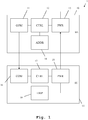
- a lighting system 1 is depicted.
- the lighting system 1 comprises a master unit 10, which comprises a communication unit 11 connected to a control unit 12, which is furthermore connected to a power supply unit 13 and an address assigning unit 14.
- the lighting system 1 comprises a slave unit 15, which comprises a communication unit 16, a control unit 17, a power supply unit 18 and a lamp 19.
- the control unit 17 is connected to the communication unit 16 and to the power supply unit 18.
- the lamp 19 is connected to the power supply unit 18.
- the communication unit 11 of the master unit 10 is connected to the communication unit 16 of the slave unit 15.
- the power supply unit 13 of the master unit 10 is connected to the power supply unit 18 of the slave unit 15.
- the power supply unit 13 of the master unit 10 furthermore comprises a mains connection.
- the power supply unit 13 of the master unit 10 is supplied with power through its mains connections.
- the power supply unit 13 processes the mains power, for example performs a transformation to a lower voltage level and a rectification and supplies the remaining components of the master unit 10 with power.
- the power supply unit 13 supplies power to the power supply unit 18 of the slave unit 15.
- the arrow connecting the power supply unit 13 and the power supply unit 18 merely indicates the direction of information flow and not the direction of power flow.
- the control unit 12 of the master unit 10 is adapted to control the function of the communication unit 11, the power supply unit 13 and the address assigning unit 14 of the master unit 10. Especially, the control unit 12 is set up for generating commands, which are transmitted to the slave unit 15 by use of the communication unit 11 of the master unit 10 and the communication unit 16 of the slave unit 15. These commands are received by the control unit 17 of the slave unit 15 from the communication unit 16 of the slave unit 15. The commands are processed by the control unit 17. For example in reaction to such a command, the lamp 19, which is a power consuming unit is activated or deactivated or dimmed. Also, the control unit 17 is adapted to generate a signal for transmitting information to the master unit 10.
- the signal is handed on to the power supply unit 18, which modulates the power consumption of the slave unit 15 according to the signal.
- this can for example be achieved by the power supply unit 18 increasing or decreasing the brightness setting of the lamp 19 or switching the lamp 19 on and off in order to increase or decrease the power consumption of the slave unit 15.
- the modulation is performed according a protocol. Due to the use of this protocol, it is possible to achieve a communication using this channel.
- the protocol can be a standard communication protocol or a proprietary protocol.
- the modulation of the power consumption can be an amplitude-shift keying, especially an off-on keying or a phase-shift keying or a frequency-shift keying.
- the power consumption of the slave unit 15 is modulated by the power supply unit 18, which is a conventional power supply unit and not set up for performing high speed modulation, the modulation frequency is advantageously below 10 Hz, preferably below 5Hz, most preferably below 1Hz. This results in a very low data rate of the signal, which can be transmitted from the slave unit 15 to the master unit 10. On the other hand, this allows for a signal transmission without any additional complex hardware.
- connection between the communication unit 11 of the master unit 10 and the communication unit 16 of the slave unit 15 can be a direct wired connection or a bus connection, for example a DALI bus or a wireless connection.
- the connection between the power supply unit 13 of the master unit 10 and the power supply unit 18 of the slave unit 15 is a wired connection.
- the control unit 12 of the master unit 10 can furthermore be set up for determining times at which the slave unit 15 is usually not in operation.
- the control unit 17 of the slave unit 15 could inform the control unit 12 of the master unit 10, when the slave unit 15 is presently not used. These times are ideal for performing the transmission from the slave unit 15 to the control unit 10, since for modulating the power consumption of the slave unit 15, it might be necessary to compromise the regular function of the slave unit 15, in this case, the function of the lamp 19.
- a second embodiment of the inventive lighting system 2 is shown.
- the lighting system 2 comprises a master unit 20, a first slave unit 25, a second slave unit 26 and a third slave unit 27.
- the master unit 20 is connected to the slave units 25 - 27 through individual wired connections, 28, 29, 30. These connections are used for connecting the communication unit of the master unit 20 to the communication units of the slave units 25 - 27.
- the master unit 20 is connected to the slave units 25 - 27 through a wired connection connecting the power supply unit of the master unit to the power supply units of the slave units 25 - 27.
- a wireless connection 48 connects a master unit 40 to slave units 45, 46 and 47.
- the wireless connection 48 is used for connecting the communication units of the central controlled unit 40 and the slave units 45 - 47.
- the master unit 40 is connected to the slave units 45 - 47 through a wired connection, connecting the power supply units of the master unit and the slave units 45 - 47.
- the master unit 20, 40 can broadcast commands to all slave units 25 - 27, 45 - 47.
- the signals broadcast by the central units 20, 40 are received by the slave units 25, 27, 45 - 47.
- the slave units 25 - 27, 45 - 47 can then each modulate the respective power consumption in order to generate a signal for transmission to the respective control unit 20, 40.
- the master unit 10 can individually target commands at slave units.
- the command comprises the respective address. Only the targeted slave unit processes the respective command and reacts thereupon.
- the address assigning unit 14 of Fig. 1 is, furthermore, adapted to assign addresses to individual slave units.
- the master unit 10 transmits an address assigning request to all connected slave units.
- an individual slave unit is selected and supplied with an address by the address assigning unit 14. This process is repeated for all connected slave units until each slave unit has been assigned an address.
- the master unit 10 of Fig. 1 can, furthermore, determine how many slave units are connected by broadcasting a command to all slave units instructing the slave units to increase or decrease the respective power consumption by a finite amount. From the resulting change in power consumption, the master unit can determine the number of connected slave units.
- a master unit of a lighting system creates and transmits a command to a slave unit of the lighting system.
- the slave unit receives the command.
- the slave unit generates a response signal by modulating the power consumed by the slave unit.
- this modulated power consumption is detected by the master unit. The signal is recreated therefrom by the master unit.
- the lighting system 2 shown in Fig. 2 can also be extended. As already described above it is possible that master unit 20 can measure the combined power consumption of slave unit 25, slave unit 26 and slave unit 27.
- slave unit 25 can be also be possible for slave unit 25 to measure the power consumption of slave unit 26 and slave unit 27 which are connected to the slave unit 25.
- a device can measure the power of devices connected "behind" such device (seen from the view of the master unit 20).
- slave unit 26 would be able to measure the power consumption of slave unit 27. With such arrangement it would be possible to send messages from slave unit 27 to slave unit 26 and slave unit 25 and to send messages from slave unit 26 to slave unit 25.
- the slave unit 25 and slave unit 26 could comprise a measurement unit to measure the power consumption of slave units connected to those slave units.
- the invention is not limited to the examples shown above. Especially, the invention can be used for communication between a master unit and a great number of different slave units.
- the slave units can be, for example, lamps, sensors, actors, etc.
- the characteristics of the exemplary embodiments can be used in any advantageous combination.
Claims (12)
- Système d'allumage (1, 2, 3) comprenant :(a) une unité maître (10, 20, 40),(b) une pluralité d'unités esclaves (15, 25, 26, 27, 45, 46, 47),
dans lequel les unités esclaves (15, 25, 26, 27, 45, 46, 47)(c) sont respectivement conçues pour consommer la puissance en mettant en oeuvre des moyens d'éclairage (19),(d) sont alimentées par une unité d'alimentation commune (13) prévue dans l'unité maître (10, 20, 40),(e) peuvent recevoir des commandes de l'unité maître (10, 20, 40),(f) sont respectivement pourvues d'une unité de commande (17) qui module la consommation de puissance de l'unité esclave (15, 25, 26, 27, 45, 46, 47) associée conformément à un protocole défini, et(g) dans lequel l'unité maître (10, 20, 40) est conçue pour mesurer la puissance consommée par toutes les unités esclaves (15, 25, 26, 27, 45, 46, 47),(h1) dans lequel les unités esclaves (15, 25, 26, 27, 45, 46, 47) sont conçues pour transmettre un signal à l'unité maître (10, 20, 40) en modulant la consommation de puissance conformément au protocole défini, et(h2) dans lequel l'unité maître (10, 20, 40) est conçue pour recréer le signal à partir de la consommation de puissance mesurée de toutes les unités esclaves (15, 25, 26, 27, 45, 46, 47) conformément au protocole défini,caractérisé en ce que
l'unité maître (10, 20, 40) est conçue pour transmettre une commande à toutes les unités esclaves (15, 25, 26, 27, 45, 46, 47) connectées ordonnant à toutes les unités esclaves (15, 25, 26, 27, 45, 46, 47) connectées d'augmenter ou de diminuer leur consommation de puissance respective d'une quantité définie,
dans lequel les unités de commande (17) de toutes les unités esclaves (15, 25, 26, 27, 45, 46, 47) connectées sont conçues pour augmenter ou diminuer la consommation de puissance de leur unité esclave (15, 25, 26, 27, 45, 46, 47) respective comme ordonné, et
dans lequel l'unité maître (10, 20, 40) est conçue pour déterminer un nombre d'unités esclaves (15, 25, 26, 27, 45, 46, 47) connectées à partir d'un changement résultant de la consommation de puissance totale de toutes les unités esclaves (15, 25, 26, 27, 45, 46, 47) connectées. - Système d'allumage (1, 2, 3) selon la revendication 1,
dans lequel les unités esclaves (15, 25, 26, 27, 45, 46, 47) comprennent chacune une unité de communication (16),
dans lequel l'unité maître (10, 20, 40) comprend une unité de communication (11),
dans lequel l'unité maître (10, 20, 40) comprend une unité de commande (12) conçue pour fournir les commandes et transmettre de manière unidirectionnelle les commandes à l'unité de communication (16) de l'unité esclave (15, 25, 26, 27, 45, 46, 47) respective en utilisant l'unité de communication (11) de l'unité maître (10, 20, 40), et
dans lequel les unités de commande (17) des unités esclaves (15, 25, 26, 27, 45, 46, 47) sont conçues pour recevoir de manière unidirectionnelle les commandes de l'unité de communication (11) de l'unité maître (10, 20, 40) en utilisant l'unité de communication (16) de l'unité esclave (15, 25, 26, 27, 45, 46, 47) respective. - Système d'allumage (1, 2, 3) selon la revendication 2,
dans lequel l'unité de communication (11) de l'unité maître (10, 20, 40) est connectée à l'unité de communication (16) de l'unité esclave (15, 25, 26, 27, 45, 46, 47) en utilisant une connexion câblée directe et/ou une connexion de bus et/ou une connexion sans fil, et
dans lequel l'unité de commande (12) de l'unité maître (10, 20, 40) est conçue pour transmettre les commandes à l'unité de commande (17) de l'unité esclave (15, 25, 26, 27, 45, 46, 47) en utilisant la connexion câblée directe et/ou la connexion de bus et/ou la connexion sans fil. - Système d'allumage (1, 2, 3) selon la revendication 2 ou 3,
dans lequel l'unité de commande (12) de l'unité maître (10, 20, 40) est conçue pour interroger l'unité de commande (17) de l'unité esclave (15, 25, 26, 27, 45, 46, 47) en utilisant l'unité de communication (11) de l'unité maître (10, 20, 40) et l'unité de communication (16) de l'unité esclave (15, 25, 26, 27, 45, 46, 47), et
dans lequel l'unité de commande (17) de l'unité esclave (15, 25, 26, 27, 45, 46, 47) est conçue pour répondre aux interrogations de l'unité de commande (12) de l'unité maître (10, 20, 40) en modulant la consommation de puissance de l'unité esclave (15, 25, 26, 27, 45, 46, 47) respective. - Système d'allumage (1, 2, 3) selon l'une quelconque des revendications 1 à 4,
dans lequel le système (1, 2, 3) comprend une unité d'attribution d'adresse (14) conçue pour attribuer des adresses à toutes les unités esclaves (15, 25, 26, 27, 45, 46, 47) connectées à l'unité maître (10, 20, 40),
dans lequel l'unité maître (10, 20, 40) est conçue pour transmettre des commandes aux unités esclaves (15, 25, 26, 27, 45, 46, 47) en utilisant les adresses attribuées aux unités esclaves (15, 25, 26, 27, 45, 46, 47), et
dans lequel les unités esclaves (15, 25, 26, 27, 45, 46, 47) sont conçues pour détecter les commandes qui leur sont destinées, et
dans lequel les unités esclaves (15, 25, 26, 27, 45, 46, 47) sont conçues pour ne traiter que les commandes destinées à leur l'unité esclave (15, 25, 26, 27, 45, 46, 47) respective. - Système d'allumage (1, 2, 3) selon l'une quelconque des revendications 1 à 5,
dans lequel les unités de commande (17) des unités esclaves (15, 25, 26, 27, 45, 46, 47) sont conçues pour moduler la consommation de puissance- en utilisant une modulation par déplacement d'amplitude, en particulier une modulation tout ou rien ou une modulation par déplacement de phase ou une modulation par déplacement de fréquence, et/ou- en utilisant une fréquence de modulation inférieure à 10 Hz, de préférence inférieure à 5 Hz, plus préférablement inférieure à 1 Hz. - Système d'allumage (1, 2, 3) selon l'une quelconque des revendications 1 à 6,
dans lequel l'unité maître (10, 20, 40) est conçue pour- détecter quand les unités esclaves (15, 25, 26, 27, 45, 46, 47) ne sont pas en fonctionnement, pour- activer au moins une unité esclave (15, 25, 26, 27, 45, 46, 47), après qu'il a été détecté que ladite au moins une unité esclave (15, 25, 26, 27, 45, 46, 47) respective n'est pas en fonctionnement, pour- ordonner à ladite au moins une unité esclave (15, 25, 26, 27, 45, 46, 47) de moduler sa consommation de puissance après que ladite au moins une unité esclave (15, 25, 26, 27, 45, 46, 47) a été activée, et pour- désactiver ladite au moins une unité esclave (15, 25, 26, 27, 45, 46, 47) après que la consommation de puissance a été modulée. - Procédé pour mettre en oeuvre un système d'allumage (1, 2, 3) selon la revendication 1, dans lequel le procédé comprend les étapes- de transmission, par l'unité maître (10, 20, 40), d'une commande à toutes les unités esclaves (15, 25, 26, 27, 45, 46, 47) connectées ordonnant à toutes les unités esclaves (15, 25, 26, 27, 45, 46, 47) connectées d'augmenter ou de diminuer leur consommation de puissance respective d'une quantité définie, et- de détermination, par l'unité maître (10, 20, 40), d'un nombre d'unités esclaves (15, 25, 26, 27, 45, 46, 47) connectées à partir d'un changement résultant de la consommation de puissance totale de toutes les unités esclaves (15, 25, 26, 27, 45, 46, 47) connectées.
- Procédé selon la revendication 8, dans lequel le procédé comprend les étapes- de transmission de manière unidirectionnelle, par l'unité maître (10, 20, 40), des commandes à l'unité esclave (15, 25, 26, 27, 45, 46, 47) respective, et- de réception de manière unidirectionnelle, par les unités esclaves (15, 25, 26, 27, 45, 46, 47), des commandes de l'unité maître (10, 20, 40).
- Procédé selon l'une quelconque des revendications 8 et 9,
dans lequel le procédé comprend les étapes- d'attribution d'adresses à toutes les unités esclaves (15, 25, 26, 27, 45, 46, 47) connectées à l'unité maître (10, 20, 40),- de transmission, par l'unité maître (10, 20, 40), de commandes aux unités esclaves (15, 25, 26, 27, 45, 46, 47) en utilisant les adresses attribuées aux unités esclaves (15, 25, 26, 27, 45, 46, 47),- de détection, par les unités esclaves (15, 25, 26, 27, 45, 46, 47), des commandes qui leur sont destinées, et- de traitement, par les unités esclaves (15, 25, 26, 27, 45, 46, 47), uniquement des commandes qui sont destinées à l'unité esclave (15, 25, 26, 27, 45, 46, 47) respective. - Procédé selon l'une quelconque des revendications 8 à 10,
dans lequel le procédé comprend l'étape de modulation, par les unités esclaves (15, 25, 26, 27, 45, 46, 47), de la consommation de puissance- en utilisant une modulation par déplacement d'amplitude, en particulier une modulation tout ou rien ou une modulation par déplacement de phase ou une modulation par déplacement de fréquence, et/ou- en utilisant une fréquence de modulation inférieure à 10 Hz, de préférence inférieure à 5 Hz, plus préférablement inférieure à 1 Hz. - Procédé selon l'une quelconque des revendications 8 à 11,
dans lequel le procédé comprend les étapes- de détection, par l'unité maître (10, 20, 40), des moments auxquels les unités esclaves (15, 25, 26, 27, 45, 46, 47) ne sont pas en fonctionnement,- d'activation, par l'unité maître (10, 20, 40), d'au moins une unité esclave (15, 25, 26, 27, 45, 46, 47), après qu'il a été détecté que ladite au moins une unité esclave (15, 25, 26, 27, 45, 46, 47) respective n'est pas en fonctionnement,- de commande, par l'unité maître (10, 20, 40), de ladite au moins une unité esclave (15, 25, 26, 27, 45, 46, 47) pour qu'elle module sa consommation de puissance après que ladite au moins une unité esclave (15, 25, 26, 27, 45, 46, 47) a été activée, et- de désactivation, par l'unité maître (10, 20, 40), de ladite au moins une unité esclave (15, 25, 26, 27, 45, 46, 47) après que la consommation de puissance a été modulée.
Priority Applications (3)
| Application Number | Priority Date | Filing Date | Title |
|---|---|---|---|
| EP14161501.3A EP2925094B1 (fr) | 2014-03-25 | 2014-03-25 | Système d'éclairage et procédé pour faire fonctionner un système d'éclairage utilisant la consommation de puissance pour la transmission d'informations. |
| US14/662,900 US9468077B2 (en) | 2014-03-25 | 2015-03-19 | Lighting system and method for operating a lighting system using power consumption for information transmission |
| CN201510127594.7A CN104955219B (zh) | 2014-03-25 | 2015-03-23 | 照明系统和用于操控照明系统的方法 |
Applications Claiming Priority (1)
| Application Number | Priority Date | Filing Date | Title |
|---|---|---|---|
| EP14161501.3A EP2925094B1 (fr) | 2014-03-25 | 2014-03-25 | Système d'éclairage et procédé pour faire fonctionner un système d'éclairage utilisant la consommation de puissance pour la transmission d'informations. |
Publications (2)
| Publication Number | Publication Date |
|---|---|
| EP2925094A1 EP2925094A1 (fr) | 2015-09-30 |
| EP2925094B1 true EP2925094B1 (fr) | 2019-01-30 |
Family
ID=50423995
Family Applications (1)
| Application Number | Title | Priority Date | Filing Date |
|---|---|---|---|
| EP14161501.3A Active EP2925094B1 (fr) | 2014-03-25 | 2014-03-25 | Système d'éclairage et procédé pour faire fonctionner un système d'éclairage utilisant la consommation de puissance pour la transmission d'informations. |
Country Status (3)
| Country | Link |
|---|---|
| US (1) | US9468077B2 (fr) |
| EP (1) | EP2925094B1 (fr) |
| CN (1) | CN104955219B (fr) |
Families Citing this family (3)
| Publication number | Priority date | Publication date | Assignee | Title |
|---|---|---|---|---|
| US10289592B1 (en) * | 2017-11-09 | 2019-05-14 | Funai Electric Co., Ltd. | Location-based address adapter and system |
| TWI721520B (zh) * | 2019-08-07 | 2021-03-11 | 新唐科技股份有限公司 | 操作裝置 |
| CN110708848B (zh) * | 2019-09-26 | 2022-03-22 | 深圳市飞鹤电子有限公司 | 灯具绑定控制方法 |
Family Cites Families (15)
| Publication number | Priority date | Publication date | Assignee | Title |
|---|---|---|---|---|
| US4593232A (en) * | 1984-01-20 | 1986-06-03 | Mcedwards Timothy K | Flame simulating apparatus |
| US5825135A (en) * | 1997-03-10 | 1998-10-20 | Chang; Chin-Hsiung | Halogen lamp control circuit assembly |
| DE19852351A1 (de) * | 1998-11-13 | 2000-05-18 | Hella Kg Hueck & Co | Diagnosesystem für eine LED-Leuchte in einem Kraftfahrzeug |
| WO2003067934A2 (fr) * | 2002-02-06 | 2003-08-14 | Color Kinetics Incorporated | Procedes et appareils d'eclairage commande |
| DE102004002027B4 (de) | 2004-01-14 | 2020-03-26 | Tridonic Gmbh & Co Kg | Zentraler PFC mit DC-Ausgangskreisregelung |
| US20090322251A1 (en) * | 2006-06-27 | 2009-12-31 | Koninklijke Philips Electronics N.V. | Large area lighting |
| US8441215B1 (en) * | 2009-03-12 | 2013-05-14 | The Active Reactor Company, Pty | Time based high intensity discharge lamp control |
| DE102010031242B4 (de) * | 2010-03-19 | 2023-02-23 | Tridonic Ag | LED-Beleuchtungssystem mit Betriebsdatenspeicher |
| US8492983B1 (en) * | 2010-05-11 | 2013-07-23 | Analog Technologies Corporation | System and method to address and control serially connected LEDs |
| US9521725B2 (en) * | 2011-07-26 | 2016-12-13 | Hunter Industries, Inc. | Systems and methods for providing power and data to lighting devices |
| US9024617B2 (en) * | 2011-09-23 | 2015-05-05 | Carrier Corporation | Non-intrusive electrical load monitoring |
| US9253845B2 (en) * | 2011-12-15 | 2016-02-02 | Terralux, Inc. | Systems and methods for data communication from an LED device to the driver system |
| US9160414B2 (en) * | 2012-09-28 | 2015-10-13 | Osram Sylvania Inc. | Transient power communication |
| JP6081795B2 (ja) * | 2012-12-27 | 2017-02-15 | 東芝ライテック株式会社 | 照明制御システム及び照明灯 |
| US20150084547A1 (en) * | 2013-09-26 | 2015-03-26 | Verified Energy, Llc | DALI commissioning tools and methods for implementing |
-
2014
- 2014-03-25 EP EP14161501.3A patent/EP2925094B1/fr active Active
-
2015
- 2015-03-19 US US14/662,900 patent/US9468077B2/en active Active
- 2015-03-23 CN CN201510127594.7A patent/CN104955219B/zh active Active
Non-Patent Citations (1)
| Title |
|---|
| None * |
Also Published As
| Publication number | Publication date |
|---|---|
| CN104955219B (zh) | 2019-03-08 |
| CN104955219A (zh) | 2015-09-30 |
| US9468077B2 (en) | 2016-10-11 |
| EP2925094A1 (fr) | 2015-09-30 |
| US20150282281A1 (en) | 2015-10-01 |
Similar Documents
| Publication | Publication Date | Title |
|---|---|---|
| US10034340B2 (en) | Electrical lighting system power control | |
| EP2979520B1 (fr) | Dispositifs de commande d'appareil d'éclairage à double mode | |
| US8463454B2 (en) | Wireless ballast control unit | |
| US8471492B2 (en) | Wireless adaptation of lighting power supply | |
| US20100204847A1 (en) | Wireless infrastructure mesh network system using a lighting node | |
| EP2976825B1 (fr) | Système de distribution de courant contin | |
| CN101414173B (zh) | 负载控制系统 | |
| EP2925094B1 (fr) | Système d'éclairage et procédé pour faire fonctionner un système d'éclairage utilisant la consommation de puissance pour la transmission d'informations. | |
| US10432239B2 (en) | Lighting device and method for supplying a wireless transmission module | |
| KR20110048257A (ko) | 무선 조명 제어 장치 및 방법 | |
| US20170055332A1 (en) | Illumination system | |
| KR101463490B1 (ko) | 통신 시스템 및 이에 사용하는 전송 유닛 | |
| US9516725B2 (en) | Distributed lighting networks | |
| CN103636291A (zh) | 照明元件的寻址方法 | |
| US20170188435A1 (en) | Apparatuses and Methods to Detect and Provision for Lighting Interfaces | |
| KR20150096057A (ko) | 블루투스를 이용한 조명 제어 시스템 | |
| JP2014067486A (ja) | 照明装置、照明器具および照明システム | |
| JP7351100B2 (ja) | 照明制御システム | |
| CN110352629B (zh) | 亮度调节器的同步系统及方法 | |
| JP2011204412A (ja) | 照明制御システム | |
| KR20140140780A (ko) | Led 조명 제어 시스템의 자동 주소 지정 장치 및 방법 | |
| JP2021174572A (ja) | 制御システムおよびコントローラ | |
| KR20110124747A (ko) | 무선 조명 제어 장치 및 방법 |
Legal Events
| Date | Code | Title | Description |
|---|---|---|---|
| PUAI | Public reference made under article 153(3) epc to a published international application that has entered the european phase |
Free format text: ORIGINAL CODE: 0009012 |
|
| AK | Designated contracting states |
Kind code of ref document: A1 Designated state(s): AL AT BE BG CH CY CZ DE DK EE ES FI FR GB GR HR HU IE IS IT LI LT LU LV MC MK MT NL NO PL PT RO RS SE SI SK SM TR |
|
| AX | Request for extension of the european patent |
Extension state: BA ME |
|
| 17P | Request for examination filed |
Effective date: 20160330 |
|
| RBV | Designated contracting states (corrected) |
Designated state(s): AL AT BE BG CH CY CZ DE DK EE ES FI FR GB GR HR HU IE IS IT LI LT LU LV MC MK MT NL NO PL PT RO RS SE SI SK SM TR |
|
| STAA | Information on the status of an ep patent application or granted ep patent |
Free format text: STATUS: EXAMINATION IS IN PROGRESS |
|
| 17Q | First examination report despatched |
Effective date: 20161209 |
|
| REG | Reference to a national code |
Ref country code: DE Ref legal event code: R079 Ref document number: 602014040252 Country of ref document: DE Free format text: PREVIOUS MAIN CLASS: H05B0037020000 Ipc: H04L0027120000 |
|
| GRAP | Despatch of communication of intention to grant a patent |
Free format text: ORIGINAL CODE: EPIDOSNIGR1 |
|
| STAA | Information on the status of an ep patent application or granted ep patent |
Free format text: STATUS: GRANT OF PATENT IS INTENDED |
|
| RIC1 | Information provided on ipc code assigned before grant |
Ipc: H04L 27/04 20060101ALI20181022BHEP Ipc: H04L 27/12 20060101AFI20181022BHEP Ipc: H04L 27/20 20060101ALI20181022BHEP Ipc: H05B 37/02 20060101ALI20181022BHEP |
|
| GRAS | Grant fee paid |
Free format text: ORIGINAL CODE: EPIDOSNIGR3 |
|
| INTG | Intention to grant announced |
Effective date: 20181121 |
|
| GRAA | (expected) grant |
Free format text: ORIGINAL CODE: 0009210 |
|
| STAA | Information on the status of an ep patent application or granted ep patent |
Free format text: STATUS: THE PATENT HAS BEEN GRANTED |
|
| AK | Designated contracting states |
Kind code of ref document: B1 Designated state(s): AL AT BE BG CH CY CZ DE DK EE ES FI FR GB GR HR HU IE IS IT LI LT LU LV MC MK MT NL NO PL PT RO RS SE SI SK SM TR |
|
| REG | Reference to a national code |
Ref country code: GB Ref legal event code: FG4D |
|
| REG | Reference to a national code |
Ref country code: CH Ref legal event code: EP |
|
| REG | Reference to a national code |
Ref country code: AT Ref legal event code: REF Ref document number: 1094127 Country of ref document: AT Kind code of ref document: T Effective date: 20190215 |
|
| REG | Reference to a national code |
Ref country code: IE Ref legal event code: FG4D |
|
| REG | Reference to a national code |
Ref country code: DE Ref legal event code: R096 Ref document number: 602014040252 Country of ref document: DE |
|
| REG | Reference to a national code |
Ref country code: LT Ref legal event code: MG4D |
|
| REG | Reference to a national code |
Ref country code: NL Ref legal event code: MP Effective date: 20190130 |
|
| PG25 | Lapsed in a contracting state [announced via postgrant information from national office to epo] |
Ref country code: PT Free format text: LAPSE BECAUSE OF FAILURE TO SUBMIT A TRANSLATION OF THE DESCRIPTION OR TO PAY THE FEE WITHIN THE PRESCRIBED TIME-LIMIT Effective date: 20190530 Ref country code: SE Free format text: LAPSE BECAUSE OF FAILURE TO SUBMIT A TRANSLATION OF THE DESCRIPTION OR TO PAY THE FEE WITHIN THE PRESCRIBED TIME-LIMIT Effective date: 20190130 Ref country code: FI Free format text: LAPSE BECAUSE OF FAILURE TO SUBMIT A TRANSLATION OF THE DESCRIPTION OR TO PAY THE FEE WITHIN THE PRESCRIBED TIME-LIMIT Effective date: 20190130 Ref country code: NO Free format text: LAPSE BECAUSE OF FAILURE TO SUBMIT A TRANSLATION OF THE DESCRIPTION OR TO PAY THE FEE WITHIN THE PRESCRIBED TIME-LIMIT Effective date: 20190430 Ref country code: NL Free format text: LAPSE BECAUSE OF FAILURE TO SUBMIT A TRANSLATION OF THE DESCRIPTION OR TO PAY THE FEE WITHIN THE PRESCRIBED TIME-LIMIT Effective date: 20190130 Ref country code: PL Free format text: LAPSE BECAUSE OF FAILURE TO SUBMIT A TRANSLATION OF THE DESCRIPTION OR TO PAY THE FEE WITHIN THE PRESCRIBED TIME-LIMIT Effective date: 20190130 Ref country code: LT Free format text: LAPSE BECAUSE OF FAILURE TO SUBMIT A TRANSLATION OF THE DESCRIPTION OR TO PAY THE FEE WITHIN THE PRESCRIBED TIME-LIMIT Effective date: 20190130 Ref country code: ES Free format text: LAPSE BECAUSE OF FAILURE TO SUBMIT A TRANSLATION OF THE DESCRIPTION OR TO PAY THE FEE WITHIN THE PRESCRIBED TIME-LIMIT Effective date: 20190130 |
|
| PG25 | Lapsed in a contracting state [announced via postgrant information from national office to epo] |
Ref country code: IS Free format text: LAPSE BECAUSE OF FAILURE TO SUBMIT A TRANSLATION OF THE DESCRIPTION OR TO PAY THE FEE WITHIN THE PRESCRIBED TIME-LIMIT Effective date: 20190530 Ref country code: HR Free format text: LAPSE BECAUSE OF FAILURE TO SUBMIT A TRANSLATION OF THE DESCRIPTION OR TO PAY THE FEE WITHIN THE PRESCRIBED TIME-LIMIT Effective date: 20190130 Ref country code: GR Free format text: LAPSE BECAUSE OF FAILURE TO SUBMIT A TRANSLATION OF THE DESCRIPTION OR TO PAY THE FEE WITHIN THE PRESCRIBED TIME-LIMIT Effective date: 20190501 Ref country code: LV Free format text: LAPSE BECAUSE OF FAILURE TO SUBMIT A TRANSLATION OF THE DESCRIPTION OR TO PAY THE FEE WITHIN THE PRESCRIBED TIME-LIMIT Effective date: 20190130 Ref country code: RS Free format text: LAPSE BECAUSE OF FAILURE TO SUBMIT A TRANSLATION OF THE DESCRIPTION OR TO PAY THE FEE WITHIN THE PRESCRIBED TIME-LIMIT Effective date: 20190130 Ref country code: BG Free format text: LAPSE BECAUSE OF FAILURE TO SUBMIT A TRANSLATION OF THE DESCRIPTION OR TO PAY THE FEE WITHIN THE PRESCRIBED TIME-LIMIT Effective date: 20190430 |
|
| PG25 | Lapsed in a contracting state [announced via postgrant information from national office to epo] |
Ref country code: SK Free format text: LAPSE BECAUSE OF FAILURE TO SUBMIT A TRANSLATION OF THE DESCRIPTION OR TO PAY THE FEE WITHIN THE PRESCRIBED TIME-LIMIT Effective date: 20190130 Ref country code: RO Free format text: LAPSE BECAUSE OF FAILURE TO SUBMIT A TRANSLATION OF THE DESCRIPTION OR TO PAY THE FEE WITHIN THE PRESCRIBED TIME-LIMIT Effective date: 20190130 Ref country code: IT Free format text: LAPSE BECAUSE OF FAILURE TO SUBMIT A TRANSLATION OF THE DESCRIPTION OR TO PAY THE FEE WITHIN THE PRESCRIBED TIME-LIMIT Effective date: 20190130 Ref country code: EE Free format text: LAPSE BECAUSE OF FAILURE TO SUBMIT A TRANSLATION OF THE DESCRIPTION OR TO PAY THE FEE WITHIN THE PRESCRIBED TIME-LIMIT Effective date: 20190130 Ref country code: CZ Free format text: LAPSE BECAUSE OF FAILURE TO SUBMIT A TRANSLATION OF THE DESCRIPTION OR TO PAY THE FEE WITHIN THE PRESCRIBED TIME-LIMIT Effective date: 20190130 Ref country code: DK Free format text: LAPSE BECAUSE OF FAILURE TO SUBMIT A TRANSLATION OF THE DESCRIPTION OR TO PAY THE FEE WITHIN THE PRESCRIBED TIME-LIMIT Effective date: 20190130 Ref country code: AL Free format text: LAPSE BECAUSE OF FAILURE TO SUBMIT A TRANSLATION OF THE DESCRIPTION OR TO PAY THE FEE WITHIN THE PRESCRIBED TIME-LIMIT Effective date: 20190130 Ref country code: MC Free format text: LAPSE BECAUSE OF FAILURE TO SUBMIT A TRANSLATION OF THE DESCRIPTION OR TO PAY THE FEE WITHIN THE PRESCRIBED TIME-LIMIT Effective date: 20190130 |
|
| REG | Reference to a national code |
Ref country code: CH Ref legal event code: PL Ref country code: DE Ref legal event code: R097 Ref document number: 602014040252 Country of ref document: DE |
|
| PG25 | Lapsed in a contracting state [announced via postgrant information from national office to epo] |
Ref country code: SM Free format text: LAPSE BECAUSE OF FAILURE TO SUBMIT A TRANSLATION OF THE DESCRIPTION OR TO PAY THE FEE WITHIN THE PRESCRIBED TIME-LIMIT Effective date: 20190130 Ref country code: LU Free format text: LAPSE BECAUSE OF NON-PAYMENT OF DUE FEES Effective date: 20190325 |
|
| REG | Reference to a national code |
Ref country code: BE Ref legal event code: MM Effective date: 20190331 |
|
| PLBE | No opposition filed within time limit |
Free format text: ORIGINAL CODE: 0009261 |
|
| STAA | Information on the status of an ep patent application or granted ep patent |
Free format text: STATUS: NO OPPOSITION FILED WITHIN TIME LIMIT |
|
| 26N | No opposition filed |
Effective date: 20191031 |
|
| PG25 | Lapsed in a contracting state [announced via postgrant information from national office to epo] |
Ref country code: CH Free format text: LAPSE BECAUSE OF NON-PAYMENT OF DUE FEES Effective date: 20190331 Ref country code: LI Free format text: LAPSE BECAUSE OF NON-PAYMENT OF DUE FEES Effective date: 20190331 Ref country code: IE Free format text: LAPSE BECAUSE OF NON-PAYMENT OF DUE FEES Effective date: 20190325 |
|
| PG25 | Lapsed in a contracting state [announced via postgrant information from national office to epo] |
Ref country code: BE Free format text: LAPSE BECAUSE OF NON-PAYMENT OF DUE FEES Effective date: 20190331 Ref country code: SI Free format text: LAPSE BECAUSE OF FAILURE TO SUBMIT A TRANSLATION OF THE DESCRIPTION OR TO PAY THE FEE WITHIN THE PRESCRIBED TIME-LIMIT Effective date: 20190130 |
|
| PG25 | Lapsed in a contracting state [announced via postgrant information from national office to epo] |
Ref country code: TR Free format text: LAPSE BECAUSE OF FAILURE TO SUBMIT A TRANSLATION OF THE DESCRIPTION OR TO PAY THE FEE WITHIN THE PRESCRIBED TIME-LIMIT Effective date: 20190130 |
|
| PGFP | Annual fee paid to national office [announced via postgrant information from national office to epo] |
Ref country code: AT Payment date: 20200319 Year of fee payment: 7 |
|
| PG25 | Lapsed in a contracting state [announced via postgrant information from national office to epo] |
Ref country code: MT Free format text: LAPSE BECAUSE OF NON-PAYMENT OF DUE FEES Effective date: 20190325 |
|
| REG | Reference to a national code |
Ref country code: AT Ref legal event code: UEP Ref document number: 1094127 Country of ref document: AT Kind code of ref document: T Effective date: 20190130 |
|
| REG | Reference to a national code |
Ref country code: DE Ref legal event code: R084 Ref document number: 602014040252 Country of ref document: DE |
|
| PG25 | Lapsed in a contracting state [announced via postgrant information from national office to epo] |
Ref country code: CY Free format text: LAPSE BECAUSE OF FAILURE TO SUBMIT A TRANSLATION OF THE DESCRIPTION OR TO PAY THE FEE WITHIN THE PRESCRIBED TIME-LIMIT Effective date: 20190130 |
|
| PG25 | Lapsed in a contracting state [announced via postgrant information from national office to epo] |
Ref country code: HU Free format text: LAPSE BECAUSE OF FAILURE TO SUBMIT A TRANSLATION OF THE DESCRIPTION OR TO PAY THE FEE WITHIN THE PRESCRIBED TIME-LIMIT; INVALID AB INITIO Effective date: 20140325 |
|
| REG | Reference to a national code |
Ref country code: AT Ref legal event code: MM01 Ref document number: 1094127 Country of ref document: AT Kind code of ref document: T Effective date: 20210325 |
|
| PG25 | Lapsed in a contracting state [announced via postgrant information from national office to epo] |
Ref country code: AT Free format text: LAPSE BECAUSE OF NON-PAYMENT OF DUE FEES Effective date: 20210325 |
|
| PG25 | Lapsed in a contracting state [announced via postgrant information from national office to epo] |
Ref country code: MK Free format text: LAPSE BECAUSE OF FAILURE TO SUBMIT A TRANSLATION OF THE DESCRIPTION OR TO PAY THE FEE WITHIN THE PRESCRIBED TIME-LIMIT Effective date: 20190130 |
|
| PGFP | Annual fee paid to national office [announced via postgrant information from national office to epo] |
Ref country code: FR Payment date: 20230323 Year of fee payment: 10 |
|
| PGFP | Annual fee paid to national office [announced via postgrant information from national office to epo] |
Ref country code: GB Payment date: 20230321 Year of fee payment: 10 Ref country code: DE Payment date: 20230328 Year of fee payment: 10 |
|
| P01 | Opt-out of the competence of the unified patent court (upc) registered |
Effective date: 20230530 |
|
| PGFP | Annual fee paid to national office [announced via postgrant information from national office to epo] |
Ref country code: DE Payment date: 20240328 Year of fee payment: 11 Ref country code: GB Payment date: 20240319 Year of fee payment: 11 |