EP2924871A1 - Motor drive system and motor control device - Google Patents
Motor drive system and motor control device Download PDFInfo
- Publication number
- EP2924871A1 EP2924871A1 EP12888720.5A EP12888720A EP2924871A1 EP 2924871 A1 EP2924871 A1 EP 2924871A1 EP 12888720 A EP12888720 A EP 12888720A EP 2924871 A1 EP2924871 A1 EP 2924871A1
- Authority
- EP
- European Patent Office
- Prior art keywords
- motor
- control device
- drive system
- torque sensor
- torque
- Prior art date
- Legal status (The legal status is an assumption and is not a legal conclusion. Google has not performed a legal analysis and makes no representation as to the accuracy of the status listed.)
- Withdrawn
Links
Images






Classifications
-
- H—ELECTRICITY
- H02—GENERATION; CONVERSION OR DISTRIBUTION OF ELECTRIC POWER
- H02P—CONTROL OR REGULATION OF ELECTRIC MOTORS, ELECTRIC GENERATORS OR DYNAMO-ELECTRIC CONVERTERS; CONTROLLING TRANSFORMERS, REACTORS OR CHOKE COILS
- H02P6/00—Arrangements for controlling synchronous motors or other dynamo-electric motors using electronic commutation dependent on the rotor position; Electronic commutators therefor
- H02P6/10—Arrangements for controlling torque ripple, e.g. providing reduced torque ripple
-
- H—ELECTRICITY
- H02—GENERATION; CONVERSION OR DISTRIBUTION OF ELECTRIC POWER
- H02P—CONTROL OR REGULATION OF ELECTRIC MOTORS, ELECTRIC GENERATORS OR DYNAMO-ELECTRIC CONVERTERS; CONTROLLING TRANSFORMERS, REACTORS OR CHOKE COILS
- H02P27/00—Arrangements or methods for the control of AC motors characterised by the kind of supply voltage
- H02P27/04—Arrangements or methods for the control of AC motors characterised by the kind of supply voltage using variable-frequency supply voltage, e.g. inverter or converter supply voltage
-
- H—ELECTRICITY
- H02—GENERATION; CONVERSION OR DISTRIBUTION OF ELECTRIC POWER
- H02K—DYNAMO-ELECTRIC MACHINES
- H02K11/00—Structural association of dynamo-electric machines with electric components or with devices for shielding, monitoring or protection
- H02K11/20—Structural association of dynamo-electric machines with electric components or with devices for shielding, monitoring or protection for measuring, monitoring, testing, protecting or switching
- H02K11/24—Devices for sensing torque, or actuated thereby
-
- H—ELECTRICITY
- H02—GENERATION; CONVERSION OR DISTRIBUTION OF ELECTRIC POWER
- H02P—CONTROL OR REGULATION OF ELECTRIC MOTORS, ELECTRIC GENERATORS OR DYNAMO-ELECTRIC CONVERTERS; CONTROLLING TRANSFORMERS, REACTORS OR CHOKE COILS
- H02P21/00—Arrangements or methods for the control of electric machines by vector control, e.g. by control of field orientation
- H02P21/14—Estimation or adaptation of machine parameters, e.g. flux, current or voltage
- H02P21/18—Estimation of position or speed
-
- H—ELECTRICITY
- H02—GENERATION; CONVERSION OR DISTRIBUTION OF ELECTRIC POWER
- H02P—CONTROL OR REGULATION OF ELECTRIC MOTORS, ELECTRIC GENERATORS OR DYNAMO-ELECTRIC CONVERTERS; CONTROLLING TRANSFORMERS, REACTORS OR CHOKE COILS
- H02P21/00—Arrangements or methods for the control of electric machines by vector control, e.g. by control of field orientation
- H02P21/14—Estimation or adaptation of machine parameters, e.g. flux, current or voltage
- H02P21/20—Estimation of torque
-
- H—ELECTRICITY
- H02—GENERATION; CONVERSION OR DISTRIBUTION OF ELECTRIC POWER
- H02P—CONTROL OR REGULATION OF ELECTRIC MOTORS, ELECTRIC GENERATORS OR DYNAMO-ELECTRIC CONVERTERS; CONTROLLING TRANSFORMERS, REACTORS OR CHOKE COILS
- H02P21/00—Arrangements or methods for the control of electric machines by vector control, e.g. by control of field orientation
- H02P21/22—Current control, e.g. using a current control loop
-
- H—ELECTRICITY
- H02—GENERATION; CONVERSION OR DISTRIBUTION OF ELECTRIC POWER
- H02P—CONTROL OR REGULATION OF ELECTRIC MOTORS, ELECTRIC GENERATORS OR DYNAMO-ELECTRIC CONVERTERS; CONTROLLING TRANSFORMERS, REACTORS OR CHOKE COILS
- H02P2205/00—Indexing scheme relating to controlling arrangements characterised by the control loops
- H02P2205/05—Torque loop, i.e. comparison of the motor torque with a torque reference
Definitions
- Disclosed embodiments relate to a motor drive system and a motor control device.
- a position and a speed (a rotational angle and a rotational speed) of the motor are generally detected by using a position sensor such as an encoder (see, for example, Patent Literature 1).
- Patent Literature 1 JP 2009-095154 A
- the position sensor such as the encoder is costly and is slightly problematic in terms of environment resistance such as vibration and shock.
- the encoder-less motor that obtains a position and a speed of the motor from a voltage and an electric current of the motor; however, it may not be capable of sufficiently compensating a torque ripple.
- One aspect of an embodiment has been made in view of the above, and an objective thereof is to provide a motor drive system and a motor control device having excellent environment resistance and being constructible at a low cost.
- a motor drive system includes: a motor; a torque sensor provided between the motor and a load; and a motor control device configured to control driving of the motor.
- the motor control device includes an estimation unit configured to estimate at least either of a speed or a position of the motor based on a torque detection signal detected by the torque sensor.
- the motor drive system and the motor control device having the excellent environment resistance and being capable of improving operational performance at a low cost.
- FIG. 1 is an explanatory diagram illustrating one example of a robot 1 to which a motor drive system according to an embodiment is applied.
- a direction substantially vertical to an installation surface G, on which the robot 1 is installed may be referred to as a vertical direction.
- the robot 1 is provided with a body unit 11 attached through a turning unit 20 to be freely turnable in a horizontal direction to a base 10, which is fixedly installed on the installation surface G, an arm unit 12 interlockingly connected to the body unit 11, and a wrist unit 13 provided to a tip of the arm unit 12.
- an end effector (not illustrated) is connected as appropriate according to purposes.
- each of the arm unit 12 and the wrist unit 13 is configured to be freely rotatable around a shaft through first to fourth joint units 21 to 24.
- the arm unit 12 is provided with a first arm unit 12a, which is connected to the body unit 11 to be freely swingable vertically through the first joint unit 21, and a second arm unit 12b, which is connected to a tip portion of the first arm unit 12a to be freely swingable vertically through the second joint unit 22.
- the wrist unit 13 is connected to the second arm unit 12b to be freely rotatable around the shaft through the third joint unit 23 and to be freely swingable vertically through the fourth joint unit 24.
- the turning unit 20 as well as the first to fourth joint units 21 to 24 incorporate an actuator for driving the body unit 11, the arm unit 12, and the wrist unit 13, which are movable members.
- the robot 1 according to this embodiment is provided with a motor 2 and a torque sensor 3 as the actuator. Then, as illustrated, the motor 2 and the torque sensor 3 are electrically connected with a motor control device 4 that controls driving of the motor 2.
- motor control device 4 is described as well as the motor drive system provided with the motor control device 4 is specifically described.
- FIG. 2A is a block diagram illustrating one example of the motor drive system.
- the first joint unit 21 is provided with the motor 2, which serves as a driving source for driving the first arm unit 12a, and the torque sensor 3, which detects torque when the motor 2 is driving.
- the torque sensor 3 is provided between the motor 2 and the first arm unit 12a, which is one example of the movable members and a load of the motor 2.
- the motor 2 and the torque sensor 3 are integrally constituted, and a sensor-integrated type motor 2a is provided in which the torque sensor 3 is integrally incorporated into the motor 2.
- FIG. 2B is a block diagram illustrating another example of the motor drive system.
- the first joint unit 21 is provided with the motor 2 and a sensor-integrated type reduction gear 5a integrally constituted of a reduction gear 5, which is interlockingly connected to the motor 2, and the torque sensor 3.
- the sensor-integrated type motor 2a or the motor 2 with the sensor-integrated type reduction gear 5a is arranged, whereby the first arm unit 12a is swung.
- illustration is omitted, note that it is also possible to employ a sensor-integrated type actuator integrally constituted of the motor 2, the reduction gear 5, and the torque sensor 3 in place of the sensor-integrated type motor 2a not provided with the reduction gear 5 or the sensor-integrated type reduction gear 5a being a separate body from the motor 2.
- the motor control device 4 which controls the driving of the motor 2, is provided with a current control unit 41, a position/speed control unit 42, and an estimation unit 43.
- the estimation unit 43 estimates either of a speed or a position of the motor 2 based on a torque detection signal T fb fed back from the torque sensor 3 and outputs a mechanical angular velocity, which is an estimation result, to the position/speed control unit 42 or an estimated electric angle to the current control unit 41. Based on the mechanical angular velocity and a speed command from the estimation unit 43, the position/speed control unit 42 outputs a current command to the current control unit 41. Accordingly, the current control unit 41 controls the motor 2 based on a feedback electric current I fb , which is a signal obtained by detecting an output current to be supplied to the motor 2 by a current detector, the estimated electric angle of the motor 2 from the estimation unit 43, and the current command from the position/speed control unit 42. Details will be described below.
- the motor control device 4 performs control of the motor 2 by using the torque sensor 3 having an excellent environment resistance without using, for example, a position detector such as an encoder, which is costly and is problematic in terms of environment resistance such as vibration and shock. Therefore, it is possible to realize a motor drive system and the motor control device 4 that are low-cost and capable of improving operational performance.
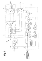
- FIG. 3 is an explanatory diagram more specifically illustrating the motor control device 4.
- the motor control device 4 is provided with a high frequency current command unit 45 that generates a high frequency current command Id hfi to be superimposed on the output current to the motor 2. That is, the estimation unit 43 of the motor control device 4 estimates at least either of the speed or the position of the motor 2 based on the high frequency current command Id hfi and the torque detection signal T fb . Note that it is not always necessary that the high frequency current command unit 45 be provided to the motor control device 4, and it is also possible to provide it as an external device separate from the motor control device 4.
- the current control unit 41 is provided with an ACR d (d-axis current controller) 51, an ACR q (q-axis current controller) 52, a three-phase/dq coordinate converter 55, a d-axis current calculator 65, adders 66 and 67, and a dq/three-phase coordinate converter 44.
- the three-phase/dq coordinate converter 55 is a coordinate conversion unit provided to the motor control device 4. It calculates a d-axis component and a q-axis component of a d-q axes rotating coordinate system, which is synchronized with the motor 2, and derives a d-axis current and a q-axis current for each of three phases of currents I uvw from the motor 2.
- the dq/three-phase coordinate converter 44 is provided with a dq coordinate conversion unit 53 and derives a three-phase voltage command V uvw from a d-axis voltage command V d and a q-axis voltage command V q .
- the current control unit 41 is also provided with a PWM controller, a switching element (power element), and a current detector that are not illustrated.
- the PWM controller by performing a so-callect carrier comparison calculation and space vector calculation, converts a three-phase voltage command into a PWM control signal and outputs it to the switching element (power element).
- the switching element (power element) is, for example, an intelligent power module (IPM), and it supplies an electric current corresponding to the PWM control signal from the PWM controller to the motor.
- the current detector is disposed to a current supply line to the motor, and it outputs a detected current signal Iuvw.
- the ACRd 51 adjusts and outputs a d-axis voltage command based on a command constituted of the detection high frequency current command Id hfi from the high frequency current command unit 45 and a d-axis current command I * d , which are synthesized by the d-axis current calculator 65, and a d-axis current value Id output from the three-phase/dq coordinate converter 55.
- the ACR d 51 adjusts the d-axis voltage command such that a deviation of the d-axis current command I * d from the d-axis current value, which is input through the three-phase/dq coordinate converter 55, is zero.
- the d-axis voltage command that has been output is synthesized with a d-axis compensation voltage Vd ff by the adder 66 and is input to the dq coordinate conversion unit 53 of a PMW controller 44.
- the ACRq 52 Based on a q-axis current command I * q from the position/speed control unit 42 and a q-axis current value Iq output from the three-phase/dq coordinate converter 55, the ACRq 52 adjusts and outputs a q-axis voltage command.
- the q-axis voltage command that has been output is synthesized with a q-axis compensation voltage Vq ff by the adder 67 and is input to the dq coordinate conversion unit 53 of the PMW controller 44.
- the position/speed control unit 42 is provided with a subtracter 68 that obtains a deviation by comparing a speed command ⁇ * with an estimated mechanical angular velocity ⁇ m , which is a mechanical angular velocity from the estimation unit 43, and an automatic speed regulator (ASR) 56 that outputs the q-axis current command I*q to the ACR q 52 of the current control unit 41.
- ASR automatic speed regulator
- the embodiment illustrated in FIG. 3 is a case where the motor control device 4 performs speed control of the motor 2.
- the motor control device 4 performs position control of the motor 2
- it is configured to further include an integrator 71, a subtracter 72, and an automatic position regulator (APR) 73.
- the integrator 71 outputs an estimated mechanical angle P ⁇ m by integrating the estimated mechanical angular velocity ⁇ m , which is the mechanical angular velocity from the estimation unit 43.
- the subtracter 72 obtains a deviation by comparing a position command P* with the estimated mechanical angle P ⁇ m .
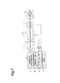
- FIG. 4 is an explanatory diagram illustrating a modification of the motor control device having the same configuration as the one illustrated in FIG. 3 other than that it is provided with the integrator 71, the subtracter 72, and the automatic position regulator (APR) 73. It is also possible to provide the integrator 71 inside the estimation unit 43. Accordingly, the estimation unit 43 becomes capable of estimating at least either of the speed or the position of the motor.
- the estimation unit 43 is provided with a bandpass filter (BPF) 57, a multiplier 64, low pass filters (LPF) 58 and 63, a subtracter 59, a PI controller 60, an integrator 61, and a mechanical angle calculation unit 62.
- BPF bandpass filter
- LPF low pass filters
- the multiplier 64 multiplies the torque detection signal T fb , which is fed back from the torque sensor 3, by the high frequency current command Id hfi , which is input from the high frequency current command unit 45.
- the torque detection signal T fb here is a vibration component of the torque extracted by the BPF 57, and this is input to the multiplier 64.
- the high frequency current command Id hfi is to be superimposed on a d-axis of the motor 2, and the BPF 57 functions as a vibration component extraction unit that extracts the vibration component of the torque when the high frequency current command Id hfi is superimposed on the d-axis.
- the frequency that has been multiplied by the multiplier 64 becomes information indicating a phase error by averaging processing is performed thereon by the LPF 58. This is input to the subtracter 59 where an electric angular velocity is adjusted such that amplitude thereof becomes zero. Then, an estimated electric angular velocity ⁇ e is derived by the PI controller 60. It is integrated by the integrator 61, whereby an estimated electric angle ⁇ e is obtained. The estimated electric angle ⁇ e that has been obtained is output to the three-phase/dq coordinate converter 55 of the current control unit 41. It is converted into the d-axis current value Id and the q-axis current value Iq on a rotating coordinate and is output to the ACR d 51 and the ACR q 52.
- the estimated electric angular velocity ⁇ e is input to the mechanical angle calculation unit 62 after noise thereof has been eliminated by the LPF 63, and is divided by the number of poles, whereby the estimated mechanical angular velocity ⁇ m is derived. Then, the estimated mechanical angular velocity ⁇ m is output to the subtracter 68 of the position/speed control unit 42.
- the motor control device 4 is capable of directly estimating the estimated mechanical angular velocity ⁇ m of the motor 2. Note that by integrating this estimated mechanical angular velocity ⁇ m , it is possible to obtain the estimated mechanical angle P ⁇ m , and as a result, it is possible to estimate at least either of the speed or the position of the motor 2. Needless to say, it is also possible to obtain the speed and the position of the motor 2.
- FIGS. 5 and 6 are explanatory diagrams illustrating the principle of estimation function by the estimation unit 43, which is provided to the motor control device 4.
- the estimated electric angle ⁇ e is delayed or advanced can be determined by multiplying the high frequency current command Id hfi , which is a detection signal superimposed on the d-axis, by the vibration component extracted by the BPF 57 (see FIG. 3 ). That is, the phase error indicated by a multiplication result of the detection signal and the vibration of the torque is expressed in a state of being offset in a positive or negative direction as illustrated.
- the electric angular velocity is adjusted such that the amplitude of the phase error becomes zero.
- the electric angular velocity is increased.
- the electric angular velocity is decreased.
- the estimated electric angular velocity ⁇ e that is adjusted such that the amplitude of the phase error becomes zero, after being denoised by the LPF 63, is input to the mechanical angle calculation unit 62 and is divided by the number of poles, and then constitutes the estimated mechanical angular velocity ⁇ m illustrated in FIGS. 3 and 4 .
- the estimated mechanical angle P ⁇ m FIG. 4 ).
- FIG. 7 is an explanatory diagram illustrating the motor drive system according to the other embodiment.
- the motor drive system is provided with an encoder 6 as a position detector that detects position of a motor 2 in addition to a torque sensor 3, and a motor control device 4 is provided with a determination unit 7 that determines whether or not the encoder 6 is in normal operation.
- an estimated mechanical angle P ⁇ m which is estimated and calculated based on a position detection signal from the encoder 6 and a torque detection signal T fb from a position/speed control unit 42 are input to the determination unit 7. Then, by comparing the detection signal from the encoder 6 with the estimated mechanical angle P ⁇ m from the position/speed control unit 42, the determination unit 7 is capable of determining there is encoder abnormality in a case where there is a difference of a predetermined value or greater.
- the position/speed control unit 42 may use the position detection signal from the encoder 6 as a position feedback signal and the torque detection signal T fb from the torque sensor 3 as a torque compensation signal.
- the position/speed control unit 42 may use the estimated mechanical angle P ⁇ m as the position feedback signal.
- the motor control device 4 may control driving of the motor 2 based on the detection signal from the encoder 6 and performs torque compensation based on the torque detection signal T fb from the torque sensor 3.
- an estimation unit 43 may estimate at least either of a speed or a position of the motor 2 based on the torque detection signal T fb from the torque sensor 3.
- the motor control can be performed based on the torque sensor 3. Therefore, it is possible to realize a fail-safe function of the motor drive system at a low cost. Furthermore, since it is possible to constantly perform the torque compensation in which a torque ripple caused by a motor structure and a reduction gear is directly detected and suppressed, improvement of operational performance of the motor drive system can be expected.
- FIG. 7A is an explanatory diagram illustrating the torque sensor 3 in a front view
- FIG. 8B is a sectional view along line I-I in FIG. 8A .
- FIG. 9A is an explanatory diagram illustrating one example of an attachment state of strain gages A1 to A4 and B1 to B4 to the torque sensor 3
- FIG. 9B is an explanatory diagram illustrating a bridge circuit assembled by the strain gages A1 to A4 and B1 to B4.
- the torque sensor 3 has a substantially disk-shaped external appearance having a predetermined thickness and diameter. Then, it is provided with a plurality of extending bodies 31 capable of being attached with the strain gages A1 to A4 and B1 to B4 and extending outward relative to an output shaft (not illustrated) of the motor 2 or an output shaft (not illustrated) of a reduction gear 5 interlockingly connected to the motor 2.
- a base end of each of the plurality (e.g. twelve) of extending bodies 31 is provided at a regular interval from each other and radially extending from a center 30a of the circular hole 30. Then, each of tips of the extending bodies 31 are connected to an outer ring-shaped body 32. Note that it is not always necessary that the outer ring-shaped body 32 be provided; however, by connecting the extending bodies 31 to the outer ring-shaped body 32, it is possible to constitute a more robust torque sensor 3.
- All of the strain gages A1 to A4 and B1 to B4 have the same configuration and, as illustrated in FIG. 9A , are provided to both sides of each of two pairs of the extending bodies 31, which are 180 degrees apart and line symmetric to each other. That is, a pair of the strain gages A1 and A2 is disposed to both sides of one extending body 31, and a pair of the strain gages A3 and A4 is disposed to both sides of an opposing extending body 31. Then, the strain gages B1 to B4 are similarly disposed to another pair of the extending bodies 31 and 31. In this way, each of the strain gages A1 to A4 and B1 to B4 is disposed in a so-called orthogonal arrangement.
- strain gages A1 to A4 and the strain gages B1 to B4 constituting the bridge circuit as illustrated in FIG. 9B it is possible to obtain an average of a bridge A output of the strain gages A1 to A4 and a bridge B output of the strain gages B1 to B4, whereby it is possible to decrease an influence of an output error on each of the bridges.
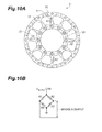
- FIG. 10A is an explanatory diagram illustrating another example of the attachment state of the strain gages to the torque sensor 3
- FIG. 10B is an explanatory diagram illustrating the bridge circuit assembled by the strain gages A1 to A4.
- strain gages A1 to A4 are provided to four extending bodies 31, respectively, at an interval of 90 degrees.
- each of pairs of the strain gage A1 and the strain gage A2 as well as the strain gage A3 and the strain gage A4 is disposed so as to be positioned on one side and the other side of the extending body 31.
- the torque sensor 3 according to this configuration is also capable of detecting torque of the motor 2 without any problem.
- a space 33 surrounded by each of the extending bodies 31, the outer ring-shaped body 32, and the inner ring-shaped body 34 is formed.
- this space 33 for example, it is possible to provide a substrate (not illustrated) having a terminal and the like enabling connection with a strain gage A amplifier and a power supply, AD conversion, and communication with outside.
- the extending body 31 is formed to be gradually tapered toward the tip according to a distance in a radial direction from the center of the output shaft.
- a tip portion width t2 of the extending body 31 is approximately 1/2 of a base end portion width t1.
- each of the extending bodies 31 may be formed to be inversely proportional to the distance from the center 30a of the circular hole 30 or it may be formed by changing a reduction ratio as appropriate from a base end side to a tip side (e.g. by increasing the reduction ratio from the base end side to the middle).
- the width of the extending body 31 is to be thinner than at least a thickness of the torque sensor 3.
- the maximum width of the extending body 31 (here, the base end portion width t1) be set to less than 1/2 or not more than 1/2 of the thickness of the extending body 31, the outer ring-shaped body 32, and the inner ring-shaped body 34.
- a dimension ratio and the like of the width and the thickness may be set as appropriate considering sensitivity and the like of the strain gages A1 to A4 and B1 to B4.
- torque detection can be performed easily and securely without any strict alignment and the like.
- the torque sensor 3 for example, when an object to be driven by the motor 2 is a movable member and a member interlockingly connected to this movable member is relatively a fixed member, the torque sensor 3 can be attached to this fixed member. Then, the motor 2 can be attached to the movable member.
- the torque sensor 3 is provided with the outer ring-shaped body 32 to which each of the tips of the plurality of extending bodies 31 is connected, it is preferred that the torque sensor 3 be fixed to the fixed member through the outer ring-shaped body 32. In this way, by attaching the torque sensor 3 to the fixed member and the motor 2 to the movable member, the torque sensor 3 is capable of effectively performing the torque detection through the outer ring-shaped body 32 by using a reaction force of a driving force of the motor 2.
- the fixed member and the movable member are relative.
- the body unit 11 when the base 10 is the fixed member, the body unit 11 is the movable member, while when the body unit 11 is the fixed member, a first arm unit 12a is the movable member.
- a wrist unit 13 when the first arm unit 12a is the fixed member, a wrist unit 13 is the movable member.
- the motor drive system is provided with the motor control device 4 having the estimation unit 43 that estimates at least either of the speed or the position based on the torque detection signal T fb detected by the torque sensor 3, which is provided between the motor 2 and the movable member to be a load.
- the estimation unit 43 of the motor control device 4 is capable of receiving a high frequency current command Id hfi from a high frequency current command unit 45and is capable of estimating at least either of the speed or the position of the motor 2 based on the high frequency current command Id hfi and the torque detection signal T fb .
- the motor drive system of this embodiment it is possible to improve environment resistance and to significantly decrease the torque ripple and the like while it is not necessary to use a costly position sensor and the like, whereby it is possible to reduce costs of the motor drive system.
- the motor drive system of this embodiment can be applied regardless of a type of a permanent magnet of the motor 2 whether it is an embedded type or a surface installation type. Therefore, for example, a high power-density surface permanent magnet motor (SPMM) in which a permanent magnet is laminated on a surface of a rotor may be used, and use of which may also contribute to downsizing of the motor 2.
- SPMM high power-density surface permanent magnet motor
- the motor drive system is applied to the robot 1; however, it may be applied to everything that is driven by the motor 2. It is also possible to change a specific configuration and the like of the torque sensor 3 as appropriate.
Landscapes
- Engineering & Computer Science (AREA)
- Power Engineering (AREA)
- Microelectronics & Electronic Packaging (AREA)
- Control Of Electric Motors In General (AREA)
- Control Of Ac Motors In General (AREA)
- Control Of Motors That Do Not Use Commutators (AREA)
- Manipulator (AREA)
Abstract
Provided is a motor drive system having an excellent environment resistance and being constructible at a low cost and a motor control device used therein. There is provided a motor, a torque sensor provided between the motor and a load, and the motor control device that controls driving of the motor. The motor control device is provided with an estimation unit that estimates at least either of a speed or a position of the motor based on a torque detection signal detected by the torque sensor.
Description
- Disclosed embodiments relate to a motor drive system and a motor control device.
- Conventionally, in a system provided with a motor, in a case where drive control is performed on the motor, a position and a speed (a rotational angle and a rotational speed) of the motor are generally detected by using a position sensor such as an encoder (see, for example, Patent Literature 1).
- Patent Literature 1:
JP 2009-095154 A - However, the position sensor such as the encoder is costly and is slightly problematic in terms of environment resistance such as vibration and shock. On the other hand, in recent years, there has been known a system using a so-called encoder-less motor that obtains a position and a speed of the motor from a voltage and an electric current of the motor; however, it may not be capable of sufficiently compensating a torque ripple.
- One aspect of an embodiment has been made in view of the above, and an objective thereof is to provide a motor drive system and a motor control device having excellent environment resistance and being constructible at a low cost.
- A motor drive system according to one aspect of an embodiment includes: a motor; a torque sensor provided between the motor and a load; and a motor control device configured to control driving of the motor. The motor control device includes an estimation unit configured to estimate at least either of a speed or a position of the motor based on a torque detection signal detected by the torque sensor.
- According to one aspect of the embodiment, it is possible to realize the motor drive system and the motor control device having the excellent environment resistance and being capable of improving operational performance at a low cost.
-
-
FIG. 1 is an explanatory diagram illustrating one example of a robot to which a motor drive system according to an embodiment is applied. -
FIG. 2A is a block diagram illustrating one example of the motor drive system. -
FIG. 2B is a block diagram illustrating another example of the motor drive system. -
FIG. 3 is an explanatory diagram illustrating a motor control device according to the embodiment. -
FIG. 4 is an explanatory diagram illustrating a modification of a motor control device. -
FIG. 5 is an explanatory diagram illustrating a principle of an estimation function by an estimation unit provided to the motor control device. -
FIG. 6 is an explanatory diagram illustrating the principle of the estimation function by the estimation unit. -
FIG. 7 is an explanatory diagram illustrating a motor drive system according to another embodiment. -
FIG. 8A is an explanatory diagram illustrating a torque sensor according to the embodiment in a front view. -
FIG. 8B is a sectional view along line I-I inFIG. 8A . -
FIG. 9A is an explanatory diagram illustrating one example of an attachment state of a strain gage to the torque sensor. -
FIG. 9B is an explanatory diagram illustrating a bridge circuit assembled by the strain gage. -
FIG. 10A is an explanatory diagram illustrating another example of the attachment state of the strain gage to the torque sensor. -
FIG. 10B is an explanatory diagram illustrating a bridge circuit assembled by the strain gage. - Hereinafter, embodiments of a motor drive system and a motor control device disclosed in the present application are described in detail with reference to the drawings. Note that the present invention is not to be limited by the embodiments described below.
-
FIG. 1 is an explanatory diagram illustrating one example of arobot 1 to which a motor drive system according to an embodiment is applied. Hereinafter, a direction substantially vertical to an installation surface G, on which therobot 1 is installed, may be referred to as a vertical direction. - As illustrated, the
robot 1 is provided with abody unit 11 attached through aturning unit 20 to be freely turnable in a horizontal direction to abase 10, which is fixedly installed on the installation surface G, anarm unit 12 interlockingly connected to thebody unit 11, and awrist unit 13 provided to a tip of thearm unit 12. At the tip of thewrist unit 13, an end effector (not illustrated) is connected as appropriate according to purposes. - Note that each of the
arm unit 12 and thewrist unit 13 is configured to be freely rotatable around a shaft through first tofourth joint units 21 to 24. Thearm unit 12 is provided with afirst arm unit 12a, which is connected to thebody unit 11 to be freely swingable vertically through thefirst joint unit 21, and asecond arm unit 12b, which is connected to a tip portion of thefirst arm unit 12a to be freely swingable vertically through thesecond joint unit 22. - The
wrist unit 13 is connected to thesecond arm unit 12b to be freely rotatable around the shaft through thethird joint unit 23 and to be freely swingable vertically through thefourth joint unit 24. - The turning
unit 20 as well as the first tofourth joint units 21 to 24 incorporate an actuator for driving thebody unit 11, thearm unit 12, and thewrist unit 13, which are movable members. Therobot 1 according to this embodiment is provided with amotor 2 and atorque sensor 3 as the actuator. Then, as illustrated, themotor 2 and thetorque sensor 3 are electrically connected with amotor control device 4 that controls driving of themotor 2. - Here, the
motor control device 4 is described as well as the motor drive system provided with themotor control device 4 is specifically described. -
FIG. 2A is a block diagram illustrating one example of the motor drive system. For example, when the motor drive system is applied to the firstjoint unit 21, as illustrated, the firstjoint unit 21 is provided with themotor 2, which serves as a driving source for driving thefirst arm unit 12a, and thetorque sensor 3, which detects torque when themotor 2 is driving. - The
torque sensor 3 is provided between themotor 2 and thefirst arm unit 12a, which is one example of the movable members and a load of themotor 2. Here, an example is illustrated in which themotor 2 and thetorque sensor 3 are integrally constituted, and a sensor-integratedtype motor 2a is provided in which thetorque sensor 3 is integrally incorporated into themotor 2. -
FIG. 2B is a block diagram illustrating another example of the motor drive system. As illustrated, the firstjoint unit 21 is provided with themotor 2 and a sensor-integratedtype reduction gear 5a integrally constituted of areduction gear 5, which is interlockingly connected to themotor 2, and thetorque sensor 3. - That is, to the first
joint unit 21 of therobot 1 illustrated inFIG. 1 , the sensor-integratedtype motor 2a or themotor 2 with the sensor-integratedtype reduction gear 5a is arranged, whereby thefirst arm unit 12a is swung. Although illustration is omitted, note that it is also possible to employ a sensor-integrated type actuator integrally constituted of themotor 2, thereduction gear 5, and thetorque sensor 3 in place of the sensor-integratedtype motor 2a not provided with thereduction gear 5 or the sensor-integratedtype reduction gear 5a being a separate body from themotor 2. - As illustrated in
FIGS. 2A and 2B , themotor control device 4, which controls the driving of themotor 2, is provided with acurrent control unit 41, a position/speed control unit 42, and anestimation unit 43. - The
estimation unit 43 estimates either of a speed or a position of themotor 2 based on a torque detection signal Tfb fed back from thetorque sensor 3 and outputs a mechanical angular velocity, which is an estimation result, to the position/speed control unit 42 or an estimated electric angle to thecurrent control unit 41. Based on the mechanical angular velocity and a speed command from theestimation unit 43, the position/speed control unit 42 outputs a current command to thecurrent control unit 41. Accordingly, thecurrent control unit 41 controls themotor 2 based on a feedback electric current Ifb, which is a signal obtained by detecting an output current to be supplied to themotor 2 by a current detector, the estimated electric angle of themotor 2 from theestimation unit 43, and the current command from the position/speed control unit 42. Details will be described below. - In this way, the
motor control device 4 according to this embodiment performs control of themotor 2 by using thetorque sensor 3 having an excellent environment resistance without using, for example, a position detector such as an encoder, which is costly and is problematic in terms of environment resistance such as vibration and shock. Therefore, it is possible to realize a motor drive system and themotor control device 4 that are low-cost and capable of improving operational performance. - Here, the
motor control device 4 is described more specifically.FIG. 3 is an explanatory diagram more specifically illustrating themotor control device 4. - As illustrated, the
motor control device 4 is provided with a high frequencycurrent command unit 45 that generates a high frequency current command Idhfi to be superimposed on the output current to themotor 2. That is, theestimation unit 43 of themotor control device 4 estimates at least either of the speed or the position of themotor 2 based on the high frequency current command Idhfi and the torque detection signal Tfb. Note that it is not always necessary that the high frequencycurrent command unit 45 be provided to themotor control device 4, and it is also possible to provide it as an external device separate from themotor control device 4. - The
current control unit 41 is provided with an ACRd (d-axis current controller) 51, an ACRq (q-axis current controller) 52, a three-phase/dq coordinateconverter 55, a d-axiscurrent calculator 65,adders converter 44. The three-phase/dq coordinateconverter 55 is a coordinate conversion unit provided to themotor control device 4. It calculates a d-axis component and a q-axis component of a d-q axes rotating coordinate system, which is synchronized with themotor 2, and derives a d-axis current and a q-axis current for each of three phases of currents Iuvw from themotor 2. The dq/three-phase coordinateconverter 44 is provided with a dq coordinateconversion unit 53 and derives a three-phase voltage command Vuvw from a d-axis voltage command Vd and a q-axis voltage command Vq. - The
current control unit 41 is also provided with a PWM controller, a switching element (power element), and a current detector that are not illustrated. The PWM controller, by performing a so-callect carrier comparison calculation and space vector calculation, converts a three-phase voltage command into a PWM control signal and outputs it to the switching element (power element). The switching element (power element) is, for example, an intelligent power module (IPM), and it supplies an electric current corresponding to the PWM control signal from the PWM controller to the motor. The current detector is disposed to a current supply line to the motor, and it outputs a detected current signal Iuvw. - The
ACRd 51 adjusts and outputs a d-axis voltage command based on a command constituted of the detection high frequency current command Idhfi from the high frequencycurrent command unit 45 and a d-axis current command I* d, which are synthesized by the d-axiscurrent calculator 65, and a d-axis current value Id output from the three-phase/dq coordinateconverter 55. Note that theACR d 51 adjusts the d-axis voltage command such that a deviation of the d-axis current command I* d from the d-axis current value, which is input through the three-phase/dq coordinateconverter 55, is zero. The d-axis voltage command that has been output is synthesized with a d-axis compensation voltage Vdff by theadder 66 and is input to the dq coordinateconversion unit 53 of aPMW controller 44. - Based on a q-axis current command I*q from the position/
speed control unit 42 and a q-axis current value Iq output from the three-phase/dq coordinateconverter 55, theACRq 52 adjusts and outputs a q-axis voltage command. The q-axis voltage command that has been output is synthesized with a q-axis compensation voltage Vqff by theadder 67 and is input to the dq coordinateconversion unit 53 of thePMW controller 44. - The position/
speed control unit 42 is provided with asubtracter 68 that obtains a deviation by comparing a speed command ω* with an estimated mechanical angular velocity ω^m, which is a mechanical angular velocity from theestimation unit 43, and an automatic speed regulator (ASR) 56 that outputs the q-axis current command I*q to theACR q 52 of thecurrent control unit 41. - Here, the embodiment illustrated in
FIG. 3 is a case where themotor control device 4 performs speed control of themotor 2. On the other hand, in a case where themotor control device 4 performs position control of themotor 2, as illustrated inFIG. 4 , preferably it is configured to further include anintegrator 71, asubtracter 72, and an automatic position regulator (APR) 73. Theintegrator 71 outputs an estimated mechanical angle P^m by integrating the estimated mechanical angular velocity ω^m, which is the mechanical angular velocity from theestimation unit 43. Thesubtracter 72 obtains a deviation by comparing a position command P* with the estimated mechanical angle P^m. The automatic position regulator (APR) 73 outputs the speed command ω* to the automatic speed regulator (ASR) 56. Note thatFIG. 4 is an explanatory diagram illustrating a modification of the motor control device having the same configuration as the one illustrated inFIG. 3 other than that it is provided with theintegrator 71, thesubtracter 72, and the automatic position regulator (APR) 73. It is also possible to provide theintegrator 71 inside theestimation unit 43. Accordingly, theestimation unit 43 becomes capable of estimating at least either of the speed or the position of the motor. - The
estimation unit 43 is provided with a bandpass filter (BPF) 57, amultiplier 64, low pass filters (LPF) 58 and 63, asubtracter 59, aPI controller 60, anintegrator 61, and a mechanicalangle calculation unit 62. - The
multiplier 64 multiplies the torque detection signal Tfb, which is fed back from thetorque sensor 3, by the high frequency current command Idhfi, which is input from the high frequencycurrent command unit 45. The torque detection signal Tfb here is a vibration component of the torque extracted by theBPF 57, and this is input to themultiplier 64. The high frequency current command Idhfi is to be superimposed on a d-axis of themotor 2, and theBPF 57 functions as a vibration component extraction unit that extracts the vibration component of the torque when the high frequency current command Idhfi is superimposed on the d-axis. - The frequency that has been multiplied by the
multiplier 64 becomes information indicating a phase error by averaging processing is performed thereon by theLPF 58. This is input to thesubtracter 59 where an electric angular velocity is adjusted such that amplitude thereof becomes zero. Then, an estimated electric angular velocity ω^e is derived by thePI controller 60. It is integrated by theintegrator 61, whereby an estimated electric angle θ^e is obtained. The estimated electric angle θ^e that has been obtained is output to the three-phase/dq coordinateconverter 55 of thecurrent control unit 41. It is converted into the d-axis current value Id and the q-axis current value Iq on a rotating coordinate and is output to theACR d 51 and theACR q 52. - On the other hand, the estimated electric angular velocity ω^e is input to the mechanical
angle calculation unit 62 after noise thereof has been eliminated by theLPF 63, and is divided by the number of poles, whereby the estimated mechanical angular velocity ω^m is derived. Then, the estimated mechanical angular velocity ω^m is output to thesubtracter 68 of the position/speed control unit 42. - Accordingly, the
motor control device 4 according to this embodiment is capable of directly estimating the estimated mechanical angular velocity ω^m of themotor 2. Note that by integrating this estimated mechanical angular velocity ω^m, it is possible to obtain the estimated mechanical angle P^m, and as a result, it is possible to estimate at least either of the speed or the position of themotor 2. Needless to say, it is also possible to obtain the speed and the position of themotor 2. - Here, a principle of speed estimation or position estimation by the
estimation unit 43 is described with reference toFIGS. 5 and6 . -
FIGS. 5 and6 are explanatory diagrams illustrating the principle of estimation function by theestimation unit 43, which is provided to themotor control device 4. - As illustrated in
FIG. 5 , when a q-axis (torque) current command I*q is input to a q-axis, the detection high frequency current command Idhfi, which is a high frequency current command, is superimposed on the d-axis. When there is no error in the estimated electric angle θ^e, the torque indicates a correct waveform as illustrated in (b). When there is an error in the estimated electric angle θ^e, however, the torque vibrates as illustrated in (a) since a vibration component of the d-axis is superimposed on the torque. In this way, by using that the torque vibrates when the estimated electric angle θ^e is shifted, the vibration component thereof is extracted by the BPF 57 (seeFIGS. 3 and4 ). - Also, as a relationship between the shift of the estimated electric angle θ^e and vibration of the torque, in a case where the estimated electric angle θ^e is delayed, the d-axis current and the vibration of the torque are in reverse phases as illustrated in
FIG. 6(a) . On the other hand, in a case where the estimated electric angle θ^e is advanced, the d-axis current and the vibration of the torque are in the same phase as illustrated inFIG. 6(b) . - Whether or not the estimated electric angle θ^e is delayed or advanced can be determined by multiplying the high frequency current command Idhfi, which is a detection signal superimposed on the d-axis, by the vibration component extracted by the BPF 57 (see
FIG. 3 ). That is, the phase error indicated by a multiplication result of the detection signal and the vibration of the torque is expressed in a state of being offset in a positive or negative direction as illustrated. - As described above, in a case where the estimated electric angular velocity ω^e is derived, the electric angular velocity is adjusted such that the amplitude of the phase error becomes zero. In this adjustment, in a case where a phase is delayed, the electric angular velocity is increased. Conversely, in a case where the phase is advanced, the electric angular velocity is decreased.
- In this way, the estimated electric angular velocity ω^e that is adjusted such that the amplitude of the phase error becomes zero, after being denoised by the
LPF 63, is input to the mechanicalangle calculation unit 62 and is divided by the number of poles, and then constitutes the estimated mechanical angular velocity ω^m illustrated inFIGS. 3 and4 . By integrating this, it is possible to obtain the estimated mechanical angle P^m (FIG. 4 ). - Here, another embodiment of a motor drive system is described.
FIG. 7 is an explanatory diagram illustrating the motor drive system according to the other embodiment. - As illustrated, the motor drive system according to this embodiment is provided with an
encoder 6 as a position detector that detects position of amotor 2 in addition to atorque sensor 3, and amotor control device 4 is provided with a determination unit 7 that determines whether or not theencoder 6 is in normal operation. - That is, while the determination unit 7 is monitoring operation of the
encoder 6, an estimated mechanical angle P^m, which is estimated and calculated based on a position detection signal from theencoder 6 and a torque detection signal Tfb from a position/speed control unit 42 are input to the determination unit 7. Then, by comparing the detection signal from theencoder 6 with the estimated mechanical angle P^m from the position/speed control unit 42, the determination unit 7 is capable of determining there is encoder abnormality in a case where there is a difference of a predetermined value or greater. - In a case where there is no abnormality in the operation of the
encoder 6, the position/speed control unit 42 may use the position detection signal from theencoder 6 as a position feedback signal and the torque detection signal Tfb from thetorque sensor 3 as a torque compensation signal. On the other hand, in a case where the abnormality of theencoder 6 is determined, the position/speed control unit 42 may use the estimated mechanical angle P^m as the position feedback signal. - In this configuration, during the normal operation, the
motor control device 4 may control driving of themotor 2 based on the detection signal from theencoder 6 and performs torque compensation based on the torque detection signal Tfb from thetorque sensor 3. On the other hand, when there is the abnormality of theencoder 6, it may allow anestimation unit 43 to estimate at least either of a speed or a position of themotor 2 based on the torque detection signal Tfb from thetorque sensor 3. - In this configuration, even in a case where a failure occurs in the
encoder 6 that has been used for motor control, the motor control can be performed based on thetorque sensor 3. Therefore, it is possible to realize a fail-safe function of the motor drive system at a low cost. Furthermore, since it is possible to constantly perform the torque compensation in which a torque ripple caused by a motor structure and a reduction gear is directly detected and suppressed, improvement of operational performance of the motor drive system can be expected. - Next, a specific configuration of the
torque sensor 3 provided to the above-described motor drive system is described.FIG. 7A is an explanatory diagram illustrating thetorque sensor 3 in a front view, and -
FIG. 8B is a sectional view along line I-I inFIG. 8A .FIG. 9A is an explanatory diagram illustrating one example of an attachment state of strain gages A1 to A4 and B1 to B4 to thetorque sensor 3, andFIG. 9B is an explanatory diagram illustrating a bridge circuit assembled by the strain gages A1 to A4 and B1 to B4. - As illustrated in
FIGS. 8A and 8B , thetorque sensor 3 has a substantially disk-shaped external appearance having a predetermined thickness and diameter. Then, it is provided with a plurality of extendingbodies 31 capable of being attached with the strain gages A1 to A4 and B1 to B4 and extending outward relative to an output shaft (not illustrated) of themotor 2 or an output shaft (not illustrated) of areduction gear 5 interlockingly connected to themotor 2. - That is, as illustrated, in a circumferential direction of an inner ring-shaped
body 34 forming acircular hole 30, into which the output shaft of themotor 2 or thereduction gear 5 is fitted, a base end of each of the plurality (e.g. twelve) of extendingbodies 31 is provided at a regular interval from each other and radially extending from acenter 30a of thecircular hole 30. Then, each of tips of the extendingbodies 31 are connected to an outer ring-shapedbody 32. Note that it is not always necessary that the outer ring-shapedbody 32 be provided; however, by connecting the extendingbodies 31 to the outer ring-shapedbody 32, it is possible to constitute a morerobust torque sensor 3. - All of the strain gages A1 to A4 and B1 to B4 have the same configuration and, as illustrated in
FIG. 9A , are provided to both sides of each of two pairs of the extendingbodies 31, which are 180 degrees apart and line symmetric to each other. That is, a pair of the strain gages A1 and A2 is disposed to both sides of one extendingbody 31, and a pair of the strain gages A3 and A4 is disposed to both sides of an opposing extendingbody 31. Then, the strain gages B1 to B4 are similarly disposed to another pair of the extendingbodies - By the strain gages A1 to A4 and the strain gages B1 to B4 constituting the bridge circuit as illustrated in
FIG. 9B , it is possible to obtain an average of a bridge A output of the strain gages A1 to A4 and a bridge B output of the strain gages B1 to B4, whereby it is possible to decrease an influence of an output error on each of the bridges. - By the way, it is also possible to configure the
torque sensor 3 in an orthogonal arrangement as illustrated inFIG. 10A and to constitute a bridge circuit as illustrated inFIG. 10B. FIG. 10A is an explanatory diagram illustrating another example of the attachment state of the strain gages to thetorque sensor 3, andFIG. 10B is an explanatory diagram illustrating the bridge circuit assembled by the strain gages A1 to A4. - That is, four strain gages A1 to A4 (or B1 to B4) are provided to four extending
bodies 31, respectively, at an interval of 90 degrees. Here, each of pairs of the strain gage A1 and the strain gage A2 as well as the strain gage A3 and the strain gage A4 is disposed so as to be positioned on one side and the other side of the extendingbody 31. Thetorque sensor 3 according to this configuration is also capable of detecting torque of themotor 2 without any problem. - By the way, to the above-described disk-shaped
torque sensor 3, aspace 33 surrounded by each of the extendingbodies 31, the outer ring-shapedbody 32, and the inner ring-shapedbody 34 is formed. By using thisspace 33, for example, it is possible to provide a substrate (not illustrated) having a terminal and the like enabling connection with a strain gage A amplifier and a power supply, AD conversion, and communication with outside. - As illustrated in
FIG. 8A , the extendingbody 31 is formed to be gradually tapered toward the tip according to a distance in a radial direction from the center of the output shaft. For example, a tip portion width t2 of the extendingbody 31 is approximately 1/2 of a base end portion width t1. Note that in a case where each of the extendingbodies 31 is formed to be tapered, it may be formed to be inversely proportional to the distance from thecenter 30a of thecircular hole 30 or it may be formed by changing a reduction ratio as appropriate from a base end side to a tip side (e.g. by increasing the reduction ratio from the base end side to the middle). - The width of the extending
body 31 is to be thinner than at least a thickness of thetorque sensor 3. For example, it is preferred that the maximum width of the extending body 31 (here, the base end portion width t1) be set to less than 1/2 or not more than 1/2 of the thickness of the extendingbody 31, the outer ring-shapedbody 32, and the inner ring-shapedbody 34. Note that a dimension ratio and the like of the width and the thickness may be set as appropriate considering sensitivity and the like of the strain gages A1 to A4 and B1 to B4. In this configuration, when attaching the strain gages A1 to A4 (B1 to B4) to the extendingbody 31, torque detection can be performed easily and securely without any strict alignment and the like. In this configuration, it is also possible to output a torque detection signal having high sensitivity to a high frequency current command to be superimposed on a d-axis. - As for the above-described arrangement position of the
torque sensor 3, for example, when an object to be driven by themotor 2 is a movable member and a member interlockingly connected to this movable member is relatively a fixed member, thetorque sensor 3 can be attached to this fixed member. Then, themotor 2 can be attached to the movable member. - As described above, since the
torque sensor 3 is provided with the outer ring-shapedbody 32 to which each of the tips of the plurality of extendingbodies 31 is connected, it is preferred that thetorque sensor 3 be fixed to the fixed member through the outer ring-shapedbody 32. In this way, by attaching thetorque sensor 3 to the fixed member and themotor 2 to the movable member, thetorque sensor 3 is capable of effectively performing the torque detection through the outer ring-shapedbody 32 by using a reaction force of a driving force of themotor 2. - The fixed member and the movable member are relative. For example, in the
robot 1 illustrated inFIG. 1 , when thebase 10 is the fixed member, thebody unit 11 is the movable member, while when thebody unit 11 is the fixed member, afirst arm unit 12a is the movable member. Similarly, when thefirst arm unit 12a is the fixed member, awrist unit 13 is the movable member. - As described above, the motor drive system according to the above-described embodiment is provided with the
motor control device 4 having theestimation unit 43 that estimates at least either of the speed or the position based on the torque detection signal Tfb detected by thetorque sensor 3, which is provided between themotor 2 and the movable member to be a load. Theestimation unit 43 of themotor control device 4 is capable of receiving a high frequency current command Idhfi from a high frequency current command unit 45and is capable of estimating at least either of the speed or the position of themotor 2 based on the high frequency current command Idhfi and the torque detection signal Tfb. - Therefore, according to the motor drive system of this embodiment, it is possible to improve environment resistance and to significantly decrease the torque ripple and the like while it is not necessary to use a costly position sensor and the like, whereby it is possible to reduce costs of the motor drive system.
- The motor drive system of this embodiment can be applied regardless of a type of a permanent magnet of the
motor 2 whether it is an embedded type or a surface installation type. Therefore, for example, a high power-density surface permanent magnet motor (SPMM) in which a permanent magnet is laminated on a surface of a rotor may be used, and use of which may also contribute to downsizing of themotor 2. - By the way, in the above-described embodiment, an example has been described in which the motor drive system is applied to the
robot 1; however, it may be applied to everything that is driven by themotor 2. It is also possible to change a specific configuration and the like of thetorque sensor 3 as appropriate. - Note that further effects and modifications may be easily derived by those skilled in the art. Accordingly, a broader aspect of the present invention is not to be limited to specific details and representative embodiments expressed and described as above. Therefore, various changes are possible without deviating from a spirit or a scope of an overall concept of the present invention defined by the attached claims and equivalents thereof.
-
- 2:
- motor
- 3:
- torque sensor
- 4:
- motor control device
- 5:
- reduction gear
- 6:
- encoder (position detector)
- 31:
- extending body
- 32:
- outer ring-shaped body
- 43:
- estimation unit
- 55:
- dq coordinate converter (coordinate conversion unit)
Claims (10)
- A motor drive system comprising:a motor;a torque sensor provided between the motor and a load; anda motor control device configured to control driving of the motor, whereinthe motor control device includes an estimation unit configured to estimate at least either of a speed or a position of the motor based on a torque detection signal detected by the torque sensor.
- The motor drive system according to claim 1, further comprising:a high frequency current command unit configured to generate a high frequency current command to be superimposed on an output current to the motor, whereinthe estimation unit of the motor control device is configured to estimate at least either of the speed or the position of the motor based on the high frequency current command and the torque detection signal.
- The motor drive system according to claim 2, wherein
the motor control device is provided with a coordinate conversion unit configured to calculate a d-axis component and a q-axis component of a d-q axes rotating coordinate system synchronized with the motor and configured to derive a d-axis current and a q-axis current, and
the estimation unit is
provided with a vibration component extraction unit configured to extract a vibration component of the q-axis current when the high frequency current command is superimposed on a d-axis, and
configured to estimate at least either of the speed or the position of the motor based on a multiplication result of the vibration component extracted by the vibration component extraction unit and the high frequency current command superimposed on the d-axis. - The motor drive system according to claim 1, 2, or 3, wherein
the torque sensor is integrally configured with the motor or a reduction gear interlockingly connected to the motor. - The motor drive system according to any one of claims 1 to 4, wherein
the torque sensor is provided with a plurality of extending bodies capable of being attached with a strain gage and extending outward relative to an output shaft of the motor or an output shaft of the reduction gear interlockingly connected to the motor. - The motor drive system according to claim 5, wherein
the extending body is formed to be gradually tapered toward a tip according to a distance in a radial direction from a center of the output shaft. - The motor drive system according to claim 5 or 6, further comprising:a fixed member and a movable member that are interlockingly connected to each other, whereinthe fixed member is attached with the torque sensor through a ring-shaped body to which each of the tips of the plurality of the extending bodies is connected, and the movable member is attached with the motor.
- The motor drive system according to any one of claims 1 to 7, further comprising:a position detector configured to detect the position of the motor, whereinthe motor control device isduring normal operation, configured to control the driving of the motor based on a detection signal of the position detector and to perform torque compensation based on the torque detection signal of the torque sensor, andwhen there is abnormality in the position detector, configured to cause the estimation unit to estimate at least either of the speed or the position of the motor based on the detection signal of the torque sensor.
- A motor control device comprising:an estimation unit configured to estimate at least either of the speed or a position based on a torque detection signal detected by a torque sensor provided between a motor and a load.
- The motor control device according to claim 9, wherein
the estimation unit of the motor control device is capable of receiving a high frequency current command from a high frequency current command unit and is configured to estimate at least either of the speed or the position of the motor based on the high frequency current command and the torque detection signal.
Applications Claiming Priority (1)
| Application Number | Priority Date | Filing Date | Title |
|---|---|---|---|
| PCT/JP2012/080092 WO2014080456A1 (en) | 2012-11-20 | 2012-11-20 | Motor drive system and motor control device |
Publications (1)
| Publication Number | Publication Date |
|---|---|
| EP2924871A1 true EP2924871A1 (en) | 2015-09-30 |
Family
ID=50775662
Family Applications (1)
| Application Number | Title | Priority Date | Filing Date |
|---|---|---|---|
| EP12888720.5A Withdrawn EP2924871A1 (en) | 2012-11-20 | 2012-11-20 | Motor drive system and motor control device |
Country Status (5)
| Country | Link |
|---|---|
| US (1) | US20150256113A1 (en) |
| EP (1) | EP2924871A1 (en) |
| JP (1) | JP6079786B2 (en) |
| CN (1) | CN104813580B (en) |
| WO (1) | WO2014080456A1 (en) |
Families Citing this family (12)
| Publication number | Priority date | Publication date | Assignee | Title |
|---|---|---|---|---|
| JP6433728B2 (en) * | 2014-09-02 | 2018-12-05 | アイシン精機株式会社 | Vehicle control device |
| JP6460927B2 (en) | 2015-06-29 | 2019-01-30 | 日立オートモティブシステムズ株式会社 | Control device for electric power steering device and electric power steering device |
| JP2017177255A (en) * | 2016-03-29 | 2017-10-05 | ソニー株式会社 | Control apparatus and control method |
| JP6502916B2 (en) * | 2016-11-17 | 2019-04-17 | ミネベアミツミ株式会社 | Motor drive control device and motor drive control method |
| EP3576298B1 (en) * | 2017-03-01 | 2020-12-16 | Panasonic Intellectual Property Management Co., Ltd. | Robot control method |
| US10270379B2 (en) * | 2017-06-14 | 2019-04-23 | Software Motor Company | Method and apparatus for quasi-sensorless adaptive control of switched reluctance motor drives |
| JP6865184B2 (en) * | 2018-02-27 | 2021-04-28 | 本田技研工業株式会社 | Drive motor and electric vehicle |
| JP6655159B2 (en) * | 2018-12-25 | 2020-02-26 | 日立オートモティブシステムズ株式会社 | Control device and control method for three-phase synchronous motor, drive device, and electric power steering device |
| JP6885436B2 (en) * | 2019-09-11 | 2021-06-16 | 富士電機株式会社 | Servo amplifier and servo system |
| JP7476309B2 (en) * | 2019-11-08 | 2024-04-30 | ミルウォーキー エレクトリック ツール コーポレイション | Motor control for gas engine conversion equipment |
| CN113031498A (en) * | 2019-12-25 | 2021-06-25 | 日本电产三协株式会社 | Robot monitoring system |
| CN112260489B (en) * | 2020-12-23 | 2021-09-03 | 北京新能源汽车股份有限公司 | Motor shaft assembly, motor assembly and vehicle |
Family Cites Families (12)
| Publication number | Priority date | Publication date | Assignee | Title |
|---|---|---|---|---|
| US4408954A (en) * | 1981-07-27 | 1983-10-11 | Earle John L | Windmill yaw and speed controls |
| JP3094091B2 (en) * | 1991-10-16 | 2000-10-03 | 工業技術院長 | Space robot controller |
| GB9316851D0 (en) * | 1993-08-13 | 1993-09-29 | Lucas Ind Plc | Enhanced position signals in optical torque sensors |
| US5969269A (en) * | 1996-10-10 | 1999-10-19 | Kop-Flex, Inc. | Flexible coupling with torque measuring and detecting device |
| JP3282541B2 (en) * | 1997-05-21 | 2002-05-13 | 株式会社日立製作所 | Motor control device |
| FR2774349B1 (en) * | 1998-02-04 | 2000-03-03 | Roulements Soc Nouvelle | STEERING COLUMN WITH COUPLEMETER |
| JP3669421B2 (en) * | 2000-04-25 | 2005-07-06 | 日産自動車株式会社 | Torque measuring device |
| JP4867067B2 (en) * | 2000-12-04 | 2012-02-01 | 富士電機株式会社 | Control device for permanent magnet type synchronous motor |
| US6737828B2 (en) * | 2001-07-19 | 2004-05-18 | Matsushita Electric Industrial Co., Ltd. | Washing machine motor drive device |
| JP2009095154A (en) | 2007-10-10 | 2009-04-30 | Yaskawa Electric Corp | Motor control device and speed detection method thereof |
| JP5534292B2 (en) * | 2008-06-30 | 2014-06-25 | 株式会社ジェイテクト | Vehicle steering system |
| JP2010029030A (en) * | 2008-07-23 | 2010-02-04 | Jtekt Corp | Motor controller |
-
2012
- 2012-11-20 CN CN201280077161.XA patent/CN104813580B/en not_active Expired - Fee Related
- 2012-11-20 WO PCT/JP2012/080092 patent/WO2014080456A1/en not_active Ceased
- 2012-11-20 EP EP12888720.5A patent/EP2924871A1/en not_active Withdrawn
- 2012-11-20 JP JP2014548357A patent/JP6079786B2/en not_active Expired - Fee Related
-
2015
- 2015-05-20 US US14/717,246 patent/US20150256113A1/en not_active Abandoned
Non-Patent Citations (1)
| Title |
|---|
| See references of WO2014080456A1 * |
Also Published As
| Publication number | Publication date |
|---|---|
| CN104813580A (en) | 2015-07-29 |
| WO2014080456A1 (en) | 2014-05-30 |
| JPWO2014080456A1 (en) | 2017-01-05 |
| US20150256113A1 (en) | 2015-09-10 |
| JP6079786B2 (en) | 2017-02-15 |
| CN104813580B (en) | 2017-09-22 |
Similar Documents
| Publication | Publication Date | Title |
|---|---|---|
| US20150256113A1 (en) | Motor drive system and motor control device | |
| EP3032735A1 (en) | Motor drive system and motor control device | |
| US9973128B2 (en) | Control device | |
| JP6613793B2 (en) | Magnetic bearing device and rotor rotation drive device | |
| EP2779415A2 (en) | Motor control system to compensate for torque ripple | |
| JP4754379B2 (en) | Electric motor control device | |
| WO2015025356A1 (en) | Motor drive system and motor control device | |
| KR101339653B1 (en) | Synchronous machine control device without position sensors | |
| JP5741611B2 (en) | AC motor control device | |
| JP6129972B2 (en) | AC motor control device, AC motor drive system, fluid pressure control system, positioning system | |
| JP2008193869A (en) | Motor control device | |
| JP4712585B2 (en) | Electric motor control device | |
| US10483882B2 (en) | Drive device | |
| JP5744151B2 (en) | Electric motor driving apparatus and electric motor driving method | |
| JP5842482B2 (en) | Motor control device and electric power steering device | |
| CN105144573A (en) | Motor drive system, motor controller, and motor | |
| JP5262267B2 (en) | Three-phase AC motor drive device | |
| WO2019163382A1 (en) | Motor control device | |
| JP2010004696A (en) | Device for estimating output, motor controller using it and motor control system | |
| JP5327503B2 (en) | Motor control device | |
| JP2009296678A (en) | Output estimating device, motor controller using the same, and motor control system | |
| JP5726243B2 (en) | Motor control device | |
| JP2013005486A (en) | Motor control device | |
| JP2012191780A (en) | Motor control device | |
| JP2019047728A (en) | Control device for three-phase synchronous motor, control method, driving device and electrically-driven power steering device |
Legal Events
| Date | Code | Title | Description |
|---|---|---|---|
| PUAI | Public reference made under article 153(3) epc to a published international application that has entered the european phase |
Free format text: ORIGINAL CODE: 0009012 |
|
| 17P | Request for examination filed |
Effective date: 20150619 |
|
| AK | Designated contracting states |
Kind code of ref document: A1 Designated state(s): AL AT BE BG CH CY CZ DE DK EE ES FI FR GB GR HR HU IE IS IT LI LT LU LV MC MK MT NL NO PL PT RO RS SE SI SK SM TR |
|
| AX | Request for extension of the european patent |
Extension state: BA ME |
|
| DAX | Request for extension of the european patent (deleted) | ||
| STAA | Information on the status of an ep patent application or granted ep patent |
Free format text: STATUS: THE APPLICATION HAS BEEN WITHDRAWN |
|
| 18W | Application withdrawn |
Effective date: 20160803 |