EP2924339A1 - Vehicle headlamp - Google Patents
Vehicle headlamp Download PDFInfo
- Publication number
- EP2924339A1 EP2924339A1 EP13856630.2A EP13856630A EP2924339A1 EP 2924339 A1 EP2924339 A1 EP 2924339A1 EP 13856630 A EP13856630 A EP 13856630A EP 2924339 A1 EP2924339 A1 EP 2924339A1
- Authority
- EP
- European Patent Office
- Prior art keywords
- light distribution
- lens
- distribution pattern
- vehicle headlamp
- light
- Prior art date
- Legal status (The legal status is an assumption and is not a legal conclusion. Google has not performed a legal analysis and makes no representation as to the accuracy of the status listed.)
- Granted
Links
- 230000003287 optical effect Effects 0.000 claims description 12
- 238000009792 diffusion process Methods 0.000 claims description 10
- 230000003595 spectral effect Effects 0.000 abstract description 10
- 239000004065 semiconductor Substances 0.000 abstract 2
- 230000002093 peripheral effect Effects 0.000 description 44
- 230000004075 alteration Effects 0.000 description 10
- 238000010586 diagram Methods 0.000 description 6
- 230000000694 effects Effects 0.000 description 4
- 239000000654 additive Substances 0.000 description 3
- 230000000996 additive effect Effects 0.000 description 3
- 230000004048 modification Effects 0.000 description 3
- 238000012986 modification Methods 0.000 description 3
- 238000005094 computer simulation Methods 0.000 description 2
- 238000007789 sealing Methods 0.000 description 2
- 239000000758 substrate Substances 0.000 description 2
- 238000000149 argon plasma sintering Methods 0.000 description 1
- 239000002131 composite material Substances 0.000 description 1
- 238000005192 partition Methods 0.000 description 1
- 239000011347 resin Substances 0.000 description 1
- 229920005989 resin Polymers 0.000 description 1
- 230000002194 synthesizing effect Effects 0.000 description 1
Images


Classifications
-
- F—MECHANICAL ENGINEERING; LIGHTING; HEATING; WEAPONS; BLASTING
- F21—LIGHTING
- F21S—NON-PORTABLE LIGHTING DEVICES; SYSTEMS THEREOF; VEHICLE LIGHTING DEVICES SPECIALLY ADAPTED FOR VEHICLE EXTERIORS
- F21S41/00—Illuminating devices specially adapted for vehicle exteriors, e.g. headlamps
- F21S41/10—Illuminating devices specially adapted for vehicle exteriors, e.g. headlamps characterised by the light source
- F21S41/14—Illuminating devices specially adapted for vehicle exteriors, e.g. headlamps characterised by the light source characterised by the type of light source
- F21S41/141—Light emitting diodes [LED]
- F21S41/143—Light emitting diodes [LED] the main emission direction of the LED being parallel to the optical axis of the illuminating device
-
- F—MECHANICAL ENGINEERING; LIGHTING; HEATING; WEAPONS; BLASTING
- F21—LIGHTING
- F21S—NON-PORTABLE LIGHTING DEVICES; SYSTEMS THEREOF; VEHICLE LIGHTING DEVICES SPECIALLY ADAPTED FOR VEHICLE EXTERIORS
- F21S41/00—Illuminating devices specially adapted for vehicle exteriors, e.g. headlamps
- F21S41/20—Illuminating devices specially adapted for vehicle exteriors, e.g. headlamps characterised by refractors, transparent cover plates, light guides or filters
- F21S41/285—Refractors, transparent cover plates, light guides or filters not provided in groups F21S41/24 - F21S41/2805
-
- F—MECHANICAL ENGINEERING; LIGHTING; HEATING; WEAPONS; BLASTING
- F21—LIGHTING
- F21S—NON-PORTABLE LIGHTING DEVICES; SYSTEMS THEREOF; VEHICLE LIGHTING DEVICES SPECIALLY ADAPTED FOR VEHICLE EXTERIORS
- F21S41/00—Illuminating devices specially adapted for vehicle exteriors, e.g. headlamps
- F21S41/10—Illuminating devices specially adapted for vehicle exteriors, e.g. headlamps characterised by the light source
- F21S41/14—Illuminating devices specially adapted for vehicle exteriors, e.g. headlamps characterised by the light source characterised by the type of light source
- F21S41/141—Light emitting diodes [LED]
- F21S41/155—Surface emitters, e.g. organic light emitting diodes [OLED]
-
- F—MECHANICAL ENGINEERING; LIGHTING; HEATING; WEAPONS; BLASTING
- F21—LIGHTING
- F21S—NON-PORTABLE LIGHTING DEVICES; SYSTEMS THEREOF; VEHICLE LIGHTING DEVICES SPECIALLY ADAPTED FOR VEHICLE EXTERIORS
- F21S41/00—Illuminating devices specially adapted for vehicle exteriors, e.g. headlamps
- F21S41/20—Illuminating devices specially adapted for vehicle exteriors, e.g. headlamps characterised by refractors, transparent cover plates, light guides or filters
- F21S41/25—Projection lenses
- F21S41/255—Lenses with a front view of circular or truncated circular outline
-
- F—MECHANICAL ENGINEERING; LIGHTING; HEATING; WEAPONS; BLASTING
- F21—LIGHTING
- F21S—NON-PORTABLE LIGHTING DEVICES; SYSTEMS THEREOF; VEHICLE LIGHTING DEVICES SPECIALLY ADAPTED FOR VEHICLE EXTERIORS
- F21S41/00—Illuminating devices specially adapted for vehicle exteriors, e.g. headlamps
- F21S41/20—Illuminating devices specially adapted for vehicle exteriors, e.g. headlamps characterised by refractors, transparent cover plates, light guides or filters
- F21S41/25—Projection lenses
- F21S41/265—Composite lenses; Lenses with a patch-like shape
-
- F—MECHANICAL ENGINEERING; LIGHTING; HEATING; WEAPONS; BLASTING
- F21—LIGHTING
- F21S—NON-PORTABLE LIGHTING DEVICES; SYSTEMS THEREOF; VEHICLE LIGHTING DEVICES SPECIALLY ADAPTED FOR VEHICLE EXTERIORS
- F21S41/00—Illuminating devices specially adapted for vehicle exteriors, e.g. headlamps
- F21S41/20—Illuminating devices specially adapted for vehicle exteriors, e.g. headlamps characterised by refractors, transparent cover plates, light guides or filters
- F21S41/25—Projection lenses
- F21S41/275—Lens surfaces, e.g. coatings or surface structures
-
- G—PHYSICS
- G02—OPTICS
- G02B—OPTICAL ELEMENTS, SYSTEMS OR APPARATUS
- G02B19/00—Condensers, e.g. light collectors or similar non-imaging optics
- G02B19/0004—Condensers, e.g. light collectors or similar non-imaging optics characterised by the optical means employed
- G02B19/0028—Condensers, e.g. light collectors or similar non-imaging optics characterised by the optical means employed refractive and reflective surfaces, e.g. non-imaging catadioptric systems
-
- G—PHYSICS
- G02—OPTICS
- G02B—OPTICAL ELEMENTS, SYSTEMS OR APPARATUS
- G02B19/00—Condensers, e.g. light collectors or similar non-imaging optics
- G02B19/0033—Condensers, e.g. light collectors or similar non-imaging optics characterised by the use
- G02B19/0047—Condensers, e.g. light collectors or similar non-imaging optics characterised by the use for use with a light source
- G02B19/0061—Condensers, e.g. light collectors or similar non-imaging optics characterised by the use for use with a light source the light source comprising a LED
-
- F—MECHANICAL ENGINEERING; LIGHTING; HEATING; WEAPONS; BLASTING
- F21—LIGHTING
- F21W—INDEXING SCHEME ASSOCIATED WITH SUBCLASSES F21K, F21L, F21S and F21V, RELATING TO USES OR APPLICATIONS OF LIGHTING DEVICES OR SYSTEMS
- F21W2102/00—Exterior vehicle lighting devices for illuminating purposes
-
- F—MECHANICAL ENGINEERING; LIGHTING; HEATING; WEAPONS; BLASTING
- F21—LIGHTING
- F21W—INDEXING SCHEME ASSOCIATED WITH SUBCLASSES F21K, F21L, F21S and F21V, RELATING TO USES OR APPLICATIONS OF LIGHTING DEVICES OR SYSTEMS
- F21W2107/00—Use or application of lighting devices on or in particular types of vehicles
- F21W2107/10—Use or application of lighting devices on or in particular types of vehicles for land vehicles
-
- F—MECHANICAL ENGINEERING; LIGHTING; HEATING; WEAPONS; BLASTING
- F21—LIGHTING
- F21Y—INDEXING SCHEME ASSOCIATED WITH SUBCLASSES F21K, F21L, F21S and F21V, RELATING TO THE FORM OR THE KIND OF THE LIGHT SOURCES OR OF THE COLOUR OF THE LIGHT EMITTED
- F21Y2115/00—Light-generating elements of semiconductor light sources
- F21Y2115/10—Light-emitting diodes [LED]
Definitions
- the present invention relates to a lens direct type vehicle headlamp provided with a semiconductor-type light source and a lens.
- the present invention relates to a vehicle headlamp that suppresses the occurrence of color bands due to spectral phenomena of a lens.
- a vehicle headlamp of this type is conventional (for example, Patent Literatures 1, 2, 3).
- Patent Literatures 1, 2, 3 a conventional vehicle headlamp will be described.
- the vehicle headlamp of Patent Literature 1 is configured such that light from a light source is reflected by a reflector, a part of the reflected light is hidden by a mask, the remaining reflected light passes through a lens, and radiates as a low beam.
- the vehicle headlamp of Patent Literature 1 is configured to suppress the occurrence of color bands by providing an area having optical scattering effects on the lens surface.
- the vehicle headlamp of Patent Literature 2 is configured such that light from a light source is reflected by a reflector, a part of the reflected light is cut off by a shade, and the remaining reflected light passes through a projection lens, and radiates as a light distribution pattern having a cutoff line.
- the projection lens comprises an upper first projection lens part having a large refractive index and a lower second projection lens part having a small refractive index, thereby suppressing the occurrence of color bands due to spectral phenomena of a lens.
- the vehicle headlamp of Patent Literature 3 is configured such that light from a semiconductor-type light source is reflected by a reflector, a part of the reflected light is cut off by a shade, the remaining reflected light passes through a projection lens, and radiates as a light distribution pattern having a cutoff line.
- a light scattering part is provided in the projection lens, thereby suppressing the occurrence of color bands due to spectral phenomena of a lens.
- a problem to be solved by the present invention is to suppress the occurrence of color bands due to spectral phenomena of a lens.
- a vehicle headlamp comprising a semiconductor-type light source and a lens, characterized in that: an emission center of the semiconductor-type light source is arranged at a reference focal point of the lens, or in the proximity thereof, at least a part of the lens is configured of an upper part and a lower part, and at least one of a light distribution pattern formed by the upper part and a light distribution pattern formed by the lower part is shifted at least one of upward and downward relative to the other light distribution patterns.
- the vehicle headlamp according to second aspect of the present invention characterized in that: the lens is configured of a first part including a reference optical axis, and a second part around the first part, and a micro-diffusion element group is provided in at least one of an incident surface and an exit surface of the second part.
- the vehicle headlamp according to third aspect of the present invention characterized in that the light distribution pattern formed by the upper part is shifted upward relative to the light distribution pattern formed by the lower part.
- the vehicle headlamp according to fourth aspect of the present invention characterized in that the light distribution pattern formed by the lower part is shifted downward relative to the light distribution pattern formed by the upper part.
- an incident surface of a lens is configured of an upper part and a lower part with respect to a reference focal point.
- a band-shaped red hereinafter referred to as "red band”
- a band-shaped blue hereinafter referred to as "blue band”
- a blue band occurs in the upper peripheral part
- a red band occurs in the lower peripheral part.
- At least one of the light distribution pattern formed by the upper part and the light distribution pattern formed by the lower part is shifted at least one of upward and downward relative to the other light distribution pattern.
- the light distribution pattern formed by the upper part is shifted upward relative to the light distribution pattern formed by the lower part.
- the light distribution pattern formed by the lower part is shifted downward relative to the light distribution pattern formed by the upper part.
- a part of the light distribution pattern formed by a part of the upper part is shifted upward relative to a part of the light distribution pattern formed by a part of the corresponding lower part, and the other part of the light distribution pattern formed by the other part of the lower part is shifted downward relative to the other part of the light distribution pattern formed by the other part of the corresponding upper part.
- the red band in the upper peripheral part of the light distribution pattern formed by the upper part substantially overlaps on the blue band in the upper peripheral part of the light distribution pattern formed by the lower part.
- the blue band in the lower peripheral part of the light distribution pattern formed by the upper part substantially overlaps on the red band in the lower peripheral part of the light distribution pattern formed by the lower part.
- a symbol “VU-VD” denotes an upper and lower vertical line of the screen.
- a symbol “HL-HR” denotes a left and right horizontal line of the screen.
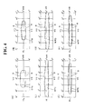
- Fig. 4 shows explanatory diagrams showing a simplified light distribution pattern on the screen plotted by computer simulation.
- Figs. 5 and 6 are explanatory diagrams of isointensity curves showing a simplified light distribution pattern on the screen plotted by computer simulation.
- the central isointensity curve shows a high intensity
- the outside isointensity curve shows a low intensity.
- front, back, top, bottom, left, right are front, back, top, bottom, left, right when a vehicle headlamp according to the present invention is mounted on a vehicle.
- a symbol 1 denotes a vehicle headlamp according to the embodiment (e.g., a headlamp).
- the vehicle headlamp 1 is mounted on the left and right ends of the front of a vehicle.
- the vehicle headlamp 1 comprises, as shown in Figs. 1 to 3 , a lamp housing (not shown), a lamp lens (not shown), a semiconductor-type light source 2, a lens 3, and a heat sink member (not shown).
- the semiconductor-type light source 2, lens 3 and the heat sink member configure a lamp unit.
- the lamp housing and the lamp lens define a lamp chamber (not shown).
- the lamp units 2, 3 are arranged in the lamp chamber, and attached to the lamp housing via a vertical direction optical axis adjustment mechanism (not shown) and a horizontal direction optical axis adjustment mechanism (not shown).
- the semiconductor-type light source 2 is, as shown in Figs. 1 to 3 , a self-emitting semiconductor-type light source, for example, an LED, OEL, or OLED (organic EL) in this example.
- the semiconductor-type light source 2 comprises one or a plurality of emitting chips (not shown), a light emitting part (package, LED package) 20 sealing the light-emitting chip with a sealing resin member, and a substrate mounting the light emitting part 20 (not shown). When two or more light-emitting chips are used, they are aligned in the X-axis direction (horizontal direction).
- the substrate is fixed to the heat sink member.
- the semiconductor-type light source 2 is held by (fixed to) the heat sink member.
- the semiconductor-type light source 2 is electrically connected to a power supply (battery).
- the light-emitting surface of the light emitting part 20 of semiconductor-type light source 2 is provided on the front side in a horizontal direction.
- the center of the light emitting surface (light emission center) O of the light emitting part 20 is located at a reference focal point F of the lens 3, or in the proximity thereof, and is located on the reference optical axis (reference axis) Z of the lens 3, or in the proximity thereof.
- X, Y, Z constitute an orthogonal coordinate (X-Y-Z orthogonal coordinate system).
- the X-axis is a horizontal axis in the lateral direction passing through the light emission center O of the light emitting part 20, and in the embodiment, the right side is a + direction, and the left side is a - direction.
- the Y-axis is a vertical axis passing through the light emission center O of the light emitting portion, and in the embodiment, the upper side is a + direction, and the lower side is a - direction.
- the Z-axis is a normal line (perpendicular line) passing through the light emission center O of the light emitting part 20, that is, an axis in the longitudinal direction orthogonal to the X-axis and Y-axis, and in the embodiment, the front side is a + direction, and the rear side is a - direction.
- the lens 3 comprises, as shown in Figs. 1 to 3 , an incident surface 30 that enters the light from the semiconductor-type light source 2 into the lens 3, and an exit surface that emits the light entered into the lens 3.
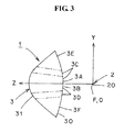
- the incident surface 30 comprises a composite secondary surface that a surface in the horizontal direction forms a concave surface with respect to the semiconductor-type light source 2 (see Fig. 2 ), and a surface in the vertical direction forms a convex surface with respect to the semiconductor-type light source 2 (see Fig. 3 ).
- the exit surface 31 forms a convex shape projecting to the opposite side of the semiconductor-type light source 2, and comprises a free-form surface.
- the lens 3 is attached to the heat sink member directly or via a holder member (not shown).
- the lens 3 radiates the light directly entered from the semiconductor-type light source 2 forward of a vehicle as a high beam light distribution pattern HP shown in Fig. 5 .
- the lens 3 is configured of an upper part and a lower part.
- the lens 3 is configured in three pairs, so that the upper part and the lower part, which are in a vertically symmetrical relationship, form a pair with respect to the horizontal line (the X axis) passing through the reference optical axis Z.
- a first upper part 3A and a first lower part 3B form a first pair
- a second upper part 3C and a second lower part 3D form a second pair
- a third upper part 3E and a third lower part 3F form a third pair.
- the upper parts 3A, 3C, 3E and the lower parts 3B, 3D, 3F are partitioned by the two-dot chain line in Figs. 2 and 3 .
- the first upper part 3A is provided in a range of latitude 0 ° to about + 15° and longitude about ⁇ 30 ° of the incident surface 30.
- the first lower part 3B is in a vertically symmetrical relationship with the first upper part 3A, and is provided in a range of latitude 0 ° to about - 15 ° and longitude about ⁇ 30 ° of the incident surface 30.
- the second upper part 3C is provided in the remaining range of the incident surface 30, excluding the range of the first upper part 3A from the range of latitude 0 ° to about + 30 ° and longitude about ⁇ 55°.
- the second lower part 3D is in a vertically symmetrical relationship with the second upper part 3C, and is provided in the remaining range of the incident surface 30, excluding the range of the first lower part 3B from the range of latitude 0 ° to about - 30 ° and longitude about ⁇ 55°.
- the third upper part 3E is provided in a range of latitude + 30 ° to about + 55 ° and longitude about ⁇ 55° of the incident surface 30.
- the third lower part 3F is in a vertically symmetrical relationship with the third upper part 3E, and is provided in a range of latitude - 30 ° to about - 55 ° and longitude about ⁇ 55° of the incident surface 30.
- the upper parts 3A, 3C, 3E and the lower parts 3B, 3D, 3F are provided respectively in the ranges corresponding to the ranges of the incident surface 30.
- the above latitude is an angle formed by the Z axis and a straight line connecting the light emission center O of the light emitting part 20 and a point on the Y axis.
- the above longitude is an angle formed by the Z axis and a straight line connecting the omission center of the light emitting part 20 and a point on the X axis.
- a boundary line between the upper parts 3A, 3C, 3E and the lower parts 3B, 3D, 3F is indicated by a solid line in Fig. 1 , and by a two-dot chain line in Figs. 2 and 3 .
- the first upper part 3A and the first lower part 3B of the first pair form a condensed light distribution pattern SPA (see Fig. 4 (A) ) and a condensed light distribution pattern SPB (see Fig. 4 (B) ), respectively, of the high beam light distribution pattern HP.
- the second upper part 3C and the second lower part 3D of the second pair form a large diffused light distribution pattern WPC (see Fig. 4 (C) ) and a large diffused light distribution pattern WPD (see Fig. 4 (D) ), respectively, of the high beam light distribution pattern HP.
- the third upper part 3E and the third lower part 3F of the third pair form a medium diffused light distribution pattern WPE (see Fig. 4 (E) ) and a medium diffused light distribution pattern WPF (see Fig. 4 (F) ), respectively, of the high beam light distribution pattern HP.
- the lens 3 comprises a first part including the reference optical axis Z, and a second part around the first part.
- the lens 3 comprises a first part that forms the condensed light distribution patterns SPA and SPB of the high beam light distribution pattern HP, and a second part that forms the large diffused light distribution patterns WPC and WPD, and the medium diffused light distribution patterns WPE and WPF of the high beam light distribution pattern HP.
- the first part comprises the first upper part 3A and the first lower lower part 3B of the first pair.
- the second part comprises the second upper part 3C and the second lower part 3D of the second pair, and the third upper part 3E and the third upper part 3F of the third pair.
- the incident surface 30 and the exit surface 31 of the lens 3 are configured to perform light distribution control of the light from the semiconductor-type light source 2, as follows.
- the condensed light distribution pattern SPA formed by the first upper part 3A is shifted about 0.9 ° upward relative to the condensed light distribution pattern SPB formed by the first lower part 3B.
- the large diffused light distribution pattern WPC formed by the second upper part 3C is shifted about 0.4 ° upward relative to the large diffused light distribution pattern WPD formed by the second lower part 3D.
- the medium diffused light distribution pattern WPE formed by the third upper part 3E is shifted about 1.2 ° upward relative to the medium diffused light distribution pattern WPF formed by the third lower part 3F.
- the vehicle headlamp according to the embodiment has the above configuration.
- the functions of the embodiment will be described.
- the light emitting part 20 of the semiconductor-type light source 2 When the light emitting part 20 of the semiconductor-type light source 2 is turned on, the light emitted from the light emitting part 20 enters directly into the lens 3 from the incident surface 30 of the lens 3. At this time, the incident light is subjected to light distribution control by the incident surface 30. The incident light that has entered into the lens 3 exits from the exit surface 31 of the lens 3. At this time, the exit light is subjected to light distribution control by the exit surface 31.
- the exit light from the lens 3 is, as shown in Fig. 5 , emitted forward of a vehicle as a high beam light distribution pattern HP having a hot zone HZ (high luminous intensity zone).
- SPB condensed light distribution pattern
- a red band R occurs in the upper peripheral part, and a blue band B occurs in the lower peripheral part, as shown in Fig. 4 (A) .
- a blue band B occurs in the upper peripheral part, and a red band R occurs in the lower peripheral part, as shown in Fig. 4 (B) .
- a red band R occurs in the upper peripheral part
- a blue band B occurs in the lower peripheral part, as shown in Fig. 4 (C) .
- a red band R occurs in the upper peripheral part
- a blue band B occurs in the lower peripheral part, as shown in Fig.
- the condensed light distribution pattern SPA formed by the first upper part 3A is, as shown in Figs. 4 (A), (B) , shifted about 0.9 ° upward relative to the condensed light distribution pattern SPB formed by the first lower part 3B.
- the red band R in the upper peripheral part of the condensed light distribution pattern SPA formed by the first upper part 3A substantially overlaps on the blue band B in the upper peripheral part of the condensed light distribution pattern SPB formed by the first lower part 3B, and the red and blue cancel each other.
- the blue band B in the lower peripheral part of the condensed light distribution pattern SPA formed by the first upper part 3A substantially overlaps on the red band R in the lower peripheral part of the condensed light distribution pattern SPB formed by the first lower part 3B, and the red and blue cancel each other.
- the large diffused light distribution pattern WPC formed by the second upper part 3C is, as shown in Figs. 4 (C), (D) , shifted about 0.4 ° upward relative to the large diffused light distribution pattern WPD formed by the second lower part 3D.
- the red band R in the upper peripheral part of the large diffused light distribution pattern WPC formed by the second upper part 3C substantially overlaps on the blue band B in the upper peripheral part of the large diffused light distribution pattern WPD formed by the second lower part 3D, and the red and blue cancel each other.
- the blue band B in the lower peripheral part of the large diffused light distribution pattern WPC formed by the second upper part 3C substantially overlaps on the red band R in the lower peripheral part of the large diffused light distribution pattern WPD formed by the second lower part 3D, and the red and blue cancel each other.
- the medium diffused light distribution pattern SPE formed by the third upper part 3E is, as shown in Figs. 4 (E), (F) , shifted about 1.2 ° upward relative to the medium diffused light distribution pattern SPF formed by the third lower part 3F.
- the red band R in the upper peripheral part of the medium diffused light distribution pattern WPE formed by the third upper part 3E substantially overlaps on the blue band B in the upper peripheral part of the medium diffused light distribution pattern WPF formed by the third lower part 3F, and the red and blue cancel each other.
- the blue band B in the lower peripheral part of the medium diffused light distribution pattern WPE formed by the third upper part 3E substantially overlaps on the blue band B in the lower peripheral part of the medium diffused light distribution pattern WPF formed by the third lower part 3F, and the red and blue cancel each other.
- a high beam light distribution pattern HP that the occurrence of color bands is suppressed based on the principle of color mixing, radiates forward of a vehicle.
- the vehicle headlamp 1 according to the embodiment has the above configuration and functions. Hereinafter, the effects of the embodiment will be described.
- the lens 3 is configured of upper parts 3A, 3C, 3E and lower parts 3B, 3D, 3F.
- a red band R occurs in the upper peripheral part
- a blue band B occurs in the lower peripheral part.
- the blue band B occurs in the upper peripheral part
- the red band R occurs in the lower peripheral part.
- the light distribution patterns SPA, WPC, WPE formed by the upper parts 3A, 3C, 3E are shifted upward relative to the light distribution patterns SPB, WPD, WPF formed by the lower parts 3B, 3D, 3F.
- the red band R in the upper peripheral part of the light distribution patterns SPA, WPC, WPE formed by the upper parts 3A, 3C, 3E substantially overlaps on the blue band B in the upper peripheral part of the light distribution patters SPB, WPD, WPF formed by the lower parts 3B, 3D, 3F.
- the blue band B in the lower peripheral part of the light distribution patterns SPA, WPC, WPE formed by the upper parts 3A, 3C, 3E substantially overlaps on the red band R in the lower peripheral part of the light distribution patterns SPB, WPD, WPF formed by the lower parts 3B, 3D, 3F.
- additive mixing it is possible to suppress the occurrence of color bands due to spectral phenomena of a lens.
- the vehicle headlamp 1 Since the light distribution patterns SPA, WPC, WPE formed by the upper parts 3A, 3C, 3E are shifted upward relative to the light distribution patterns SPB, WPD, WPF formed by the lower parts 3B, 3D, 3F, the vehicle headlamp 1 according to the embodiment is able to suppress the occurrence of a blue band B (a band of blue color) whose band width becomes wider in accordance with the refractive index depending on the wavelength.
- a blue band B a band of blue color
- the vehicle headlamp 1 Since the light distribution patterns SPA, WPC, WPE formed by the upper parts 3A, 3C, 3E are shifted upward relative to the light distribution patterns SPB, WPD, WPF formed by the lower parts 3B, 3D, 3F, the vehicle headlamp 1 according to the embodiment is optimal for a high beam light distribution pattern HP.
- a micro-diffusion element group is provided in a part of at least one of the second parts 3C, 3D, 3E, 3F of the incident surface 30 of the lens 3 and the exit surface 31.
- the part above the upper boundary line of the first upper part 3A (the upper boundary line indicated by the two-dot chain line in Fig. 1 , that is, the boundary line of latitude about + 15 °)
- the part below the lower boundary line of the first lower part 3B (the lower boundary line indicated by the two-dot chain line in Fig. 1 , that is, the boundary line of latitude about - 15 °).
- a part of the second parts 3C, 3D, 3E, 3F is, at maximum, the part above the upper boundary line of the first upper part 3A of the second upper part 3C, the third upper part 3E, the part below the lower boundary line of the first lower part 3B of the second lower part 3D, and the third lower part 3F.
- the micro-diffusion element group is configured of a concave surface, a convex surface, or an uneven surface of a micrometer order. Thus, light entering the micro-diffusion element group diffuses. Further, the micro-diffusion element group may be provided on all surfaces of the incident surface 30 and the exit surface 31, except the first part 3A, 3B.
- a micro-diffusion element group is provided at least in a part of the second parts 3C, 3D, 3E, 3F of the lens 3, that is, the upper and lower end portions of one of the incident surface 30 and the exit surface 31 of the lens 3.
- the red band R in the upper peripheral part of the light distribution patterns WPC, WPE formed by the upper parts 3C, 3E substantially overlaps on the blue band B in the upper peripheral part of the light distribution patterns WPD, WPF formed by the lower parts 3D, 3F.
- the blue band B in the lower peripheral part of the light distribution patterns WPC, WPE formed by the upper parts 3C, 3E substantially overlaps on the red band R in the lower peripheral part of the light distribution patterns WPD, WPF formed by the lower parts 3D, 3F. Therefore, based on the principle of color mixing (additive mixing), it is possible to more securely suppress the occurrence of color bands due to spectral phenomena of a lens.
- a micro-diffusion element group is provided at least in a part of the second parts 3C, 3D, 3E, 3F of the lens 3, that is, the upper and lower end portions of one of the incident surface 30 and the exit surface 31 of the lens 3.
- the hot zone HZ1 high luminous intensity zone
- the embodiment is configured to radiate the high beam light distribution pattern HP, HP1.
- HP high beam light distribution pattern
- HP1 low beam light distribution pattern
- fog lamp light distribution pattern a light distribution pattern other than the high beam light distribution pattern HP, HP1, for example, a low beam light distribution pattern and a fog lamp light distribution pattern.
- the light distribution patterns SPA, WPC, WPE formed by the upper parts 3A, 3C, 3E are shifted upward relative to the light distribution patterns SPB, WPD, WPF formed by the lower parts 3B, 3D, 3F.
- the light distribution patterns SPA, WPC, WPE formed by the upper parts 3A, 3C, 3E may be shifted downward relative to the light distribution patterns SPB, WPD, WPF formed by the lower parts 3B, 3D, 3F.
- the present invention is suitable for a light distribution pattern having a horizontal cutoff line, such as, a low beam light distribution pattern and a fog lamp light distribution pattern.
- a part of the light distribution patterns SPA, WPC, WPE formed by a part of the upper parts 3A, 3C, 3E may be shifted upward relative to a part of the light distribution patterns SPB, WPD, WPF formed by the corresponding lower parts 3B, 3D, 3F, and the other parts of the light distribution patterns SPA, WPC, WPE formed by the other parts of the upper parts 3A, 3C, 3E may be shifted downward relative to the other parts of the light distribution patterns SPB, WPD, WPF formed by the other parts of the corresponding lower parts 3B, 3D, 3F.
- the lens 3 is configured in three pairs, so that the upper parts 3A, 3C, 3E and the lower parts 3B, 3D, 3F, which are in a vertically symmetrical relationship, form pairs with respect to the horizontal line (the X axis) passing through the reference optical axis Z,.
- the upper part and the lower part may be one pair, two pairs, and four pairs or more.
- the light distribution pattern formed by the upper part and the light distribution pattern formed by the lower part becomes a predetermined light distribution pattern of one by one, two by two, or by four or more.
- the lens 3 is, as a whole, configured in three pairs, so that the upper parts 3A, 3C, 3E and the lower parts 3B, 3D, 3F, which are in a vertically symmetrical relationship, form pairs with respect to the horizontal line (the X axis) passing through the reference optical axis Z.
- a part of the lens 3 may be configured in one pair or more pairs, so that the upper part and the lower part, which are in a vertically symmetrical relationship, form a pair with respect to the horizontal line (the X axis) passing through the reference optical axis Z.
- the first upper part 3A and the first lower part 3B may form a pair, and the other parts may not form a pair, and may be an ordinary incident surface.
Landscapes
- Engineering & Computer Science (AREA)
- Physics & Mathematics (AREA)
- Optics & Photonics (AREA)
- General Engineering & Computer Science (AREA)
- Microelectronics & Electronic Packaging (AREA)
- General Physics & Mathematics (AREA)
- Non-Portable Lighting Devices Or Systems Thereof (AREA)
Abstract
Description
- The present invention relates to a lens direct type vehicle headlamp provided with a semiconductor-type light source and a lens. In particular, the present invention relates to a vehicle headlamp that suppresses the occurrence of color bands due to spectral phenomena of a lens.
- A vehicle headlamp of this type is conventional (for example,
Patent Literatures - The vehicle headlamp of
Patent Literature 1 is configured such that light from a light source is reflected by a reflector, a part of the reflected light is hidden by a mask, the remaining reflected light passes through a lens, and radiates as a low beam. The vehicle headlamp ofPatent Literature 1 is configured to suppress the occurrence of color bands by providing an area having optical scattering effects on the lens surface. - The vehicle headlamp of
Patent Literature 2 is configured such that light from a light source is reflected by a reflector, a part of the reflected light is cut off by a shade, and the remaining reflected light passes through a projection lens, and radiates as a light distribution pattern having a cutoff line. In the vehicle headlamp ofPatent Literature 2, the projection lens comprises an upper first projection lens part having a large refractive index and a lower second projection lens part having a small refractive index, thereby suppressing the occurrence of color bands due to spectral phenomena of a lens. - Further, the vehicle headlamp of
Patent Literature 3 is configured such that light from a semiconductor-type light source is reflected by a reflector, a part of the reflected light is cut off by a shade, the remaining reflected light passes through a projection lens, and radiates as a light distribution pattern having a cutoff line. In the vehicle headlamp ofPatent Literature 3, a light scattering part is provided in the projection lens, thereby suppressing the occurrence of color bands due to spectral phenomena of a lens. -
- Patent Literature 1:
JP-A-2005-302718 - Patent Literature 2:
JP-A-2009-181845 - Patent Literature 3:
JP-A-2009-199938 - In such a vehicle headlamp, it is important to suppress the occurrence of color bands due to spectral phenomena of a lens.
- A problem to be solved by the present invention is to suppress the occurrence of color bands due to spectral phenomena of a lens.
- A vehicle headlamp according to first aspect of the present invention, comprising a semiconductor-type light source and a lens, characterized in that: an emission center of the semiconductor-type light source is arranged at a reference focal point of the lens, or in the proximity thereof, at least a part of the lens is configured of an upper part and a lower part, and at least one of a light distribution pattern formed by the upper part and a light distribution pattern formed by the lower part is shifted at least one of upward and downward relative to the other light distribution patterns.
- The vehicle headlamp according to second aspect of the present invention, characterized in that: the lens is configured of a first part including a reference optical axis, and a second part around the first part, and a micro-diffusion element group is provided in at least one of an incident surface and an exit surface of the second part.
- The vehicle headlamp according to third aspect of the present invention, characterized in that the light distribution pattern formed by the upper part is shifted upward relative to the light distribution pattern formed by the lower part.
- The vehicle headlamp according to fourth aspect of the present invention, characterized in that the light distribution pattern formed by the lower part is shifted downward relative to the light distribution pattern formed by the upper part.
- In the vehicle headlamp of the present invention, an incident surface of a lens is configured of an upper part and a lower part with respect to a reference focal point. Thus, due to chromatic aberrations of a lens, in a light distribution pattern formed by the upper part, a band-shaped red (hereinafter referred to as "red band") occurs in the upper peripheral part, and a band-shaped blue (hereinafter referred to as "blue band") occurs in the lower peripheral part. On the other hand, due to chromatic aberrations of a lens, in a light distribution pattern formed by the lower part, a blue band occurs in the upper peripheral part, and a red band occurs in the lower peripheral part.
- In the vehicle headlamp of the invention, at least one of the light distribution pattern formed by the upper part and the light distribution pattern formed by the lower part is shifted at least one of upward and downward relative to the other light distribution pattern. In other words, the light distribution pattern formed by the upper part is shifted upward relative to the light distribution pattern formed by the lower part. Or, the light distribution pattern formed by the lower part is shifted downward relative to the light distribution pattern formed by the upper part. Or, a part of the light distribution pattern formed by a part of the upper part is shifted upward relative to a part of the light distribution pattern formed by a part of the corresponding lower part, and the other part of the light distribution pattern formed by the other part of the lower part is shifted downward relative to the other part of the light distribution pattern formed by the other part of the corresponding upper part.
- As a result, in the vehicle headlamp of the invention, the red band in the upper peripheral part of the light distribution pattern formed by the upper part substantially overlaps on the blue band in the upper peripheral part of the light distribution pattern formed by the lower part. Further, the blue band in the lower peripheral part of the light distribution pattern formed by the upper part substantially overlaps on the red band in the lower peripheral part of the light distribution pattern formed by the lower part. Thus, based on the principle of color mixing (additive mixing), it is possible to suppress the occurrence of color bands due to spectral phenomena of a lens.
-
-
Fig. 1 is a rear view of a lens and a semiconductor-type light source showing an embodiment of the vehicle headlamp according to the present invention. -
Fig. 2 is a plan view (a view taken along the arrow II inFig. 1 ) showing a lens and a semiconductor-type light source. -
Fig. 3 is a side view (a view taken along the arrow III inFig. 1 ) showing a lens and a semiconductor-type light source. -
Fig. 4 shows explanatory diagrams showing a light distribution pattern of each configuration (section) of a lens. -
Fig. 5 is an explanatory diagram showing a high beam light distribution pattern formed by superimposing (synthesizing) a light distribution pattern of each configuration (partition) of a lens. -
Fig. 6 is an explanatory diagram showing a high beam light distribution pattern in the case when a micro-diffusion element group is provided in a lens. - Hereinafter, embodiments (examples) of the present invention will be described with reference to the drawings. The invention is not limited to the embodiments. In
Figs. 4 to 6 , a symbol "VU-VD" denotes an upper and lower vertical line of the screen. A symbol "HL-HR" denotes a left and right horizontal line of the screen.Fig. 4 shows explanatory diagrams showing a simplified light distribution pattern on the screen plotted by computer simulation.Figs. 5 and 6 are explanatory diagrams of isointensity curves showing a simplified light distribution pattern on the screen plotted by computer simulation. In the explanatory diagrams of isointensity curves, the central isointensity curve shows a high intensity, the outside isointensity curve shows a low intensity. In this specification and claims, front, back, top, bottom, left, right are front, back, top, bottom, left, right when a vehicle headlamp according to the present invention is mounted on a vehicle. - Hereinafter, a configuration of the vehicle headlamp according to the embodiment will be described. In the drawings, a
symbol 1 denotes a vehicle headlamp according to the embodiment (e.g., a headlamp). Thevehicle headlamp 1 is mounted on the left and right ends of the front of a vehicle. - The
vehicle headlamp 1 comprises, as shown inFigs. 1 to 3 , a lamp housing (not shown), a lamp lens (not shown), a semiconductor-type light source 2, alens 3, and a heat sink member (not shown). - The semiconductor-
type light source 2,lens 3 and the heat sink member configure a lamp unit. The lamp housing and the lamp lens define a lamp chamber (not shown). Thelamp units - The semiconductor-
type light source 2 is, as shown inFigs. 1 to 3 , a self-emitting semiconductor-type light source, for example, an LED, OEL, or OLED (organic EL) in this example. The semiconductor-type light source 2 comprises one or a plurality of emitting chips (not shown), a light emitting part (package, LED package) 20 sealing the light-emitting chip with a sealing resin member, and a substrate mounting the light emitting part 20 (not shown). When two or more light-emitting chips are used, they are aligned in the X-axis direction (horizontal direction). - The substrate is fixed to the heat sink member. As a result, the semiconductor-
type light source 2 is held by (fixed to) the heat sink member. The semiconductor-type light source 2 is electrically connected to a power supply (battery). The light-emitting surface of thelight emitting part 20 of semiconductor-type light source 2 is provided on the front side in a horizontal direction. The center of the light emitting surface (light emission center) O of thelight emitting part 20 is located at a reference focal point F of thelens 3, or in the proximity thereof, and is located on the reference optical axis (reference axis) Z of thelens 3, or in the proximity thereof. - In
Figs. 1 to 3 , X, Y, Z constitute an orthogonal coordinate (X-Y-Z orthogonal coordinate system). The X-axis is a horizontal axis in the lateral direction passing through the light emission center O of thelight emitting part 20, and in the embodiment, the right side is a + direction, and the left side is a - direction. The Y-axis is a vertical axis passing through the light emission center O of the light emitting portion, and in the embodiment, the upper side is a + direction, and the lower side is a - direction. Further, the Z-axis is a normal line (perpendicular line) passing through the light emission center O of thelight emitting part 20, that is, an axis in the longitudinal direction orthogonal to the X-axis and Y-axis, and in the embodiment, the front side is a + direction, and the rear side is a - direction. - The
lens 3 comprises, as shown inFigs. 1 to 3 , anincident surface 30 that enters the light from the semiconductor-type light source 2 into thelens 3, and an exit surface that emits the light entered into thelens 3. Theincident surface 30 comprises a composite secondary surface that a surface in the horizontal direction forms a concave surface with respect to the semiconductor-type light source 2 (seeFig. 2 ), and a surface in the vertical direction forms a convex surface with respect to the semiconductor-type light source 2 (seeFig. 3 ). Theexit surface 31 forms a convex shape projecting to the opposite side of the semiconductor-type light source 2, and comprises a free-form surface. - The
lens 3 is attached to the heat sink member directly or via a holder member (not shown). Thelens 3 radiates the light directly entered from the semiconductor-type light source 2 forward of a vehicle as a high beam light distribution pattern HP shown inFig. 5 . - The
lens 3 is configured of an upper part and a lower part. In other words, thelens 3 is configured in three pairs, so that the upper part and the lower part, which are in a vertically symmetrical relationship, form a pair with respect to the horizontal line (the X axis) passing through the reference optical axis Z. In the example, a firstupper part 3A and a firstlower part 3B form a first pair, a secondupper part 3C and a secondlower part 3D form a second pair, and a thirdupper part 3E and a thirdlower part 3F form a third pair. Theupper parts lower parts Figs. 2 and3 . - The first
upper part 3A is provided in a range of latitude 0 ° to about + 15° and longitude about ± 30 ° of theincident surface 30. The firstlower part 3B is in a vertically symmetrical relationship with the firstupper part 3A, and is provided in a range of latitude 0 ° to about - 15 ° and longitude about ± 30 ° of theincident surface 30. The secondupper part 3C is provided in the remaining range of theincident surface 30, excluding the range of the firstupper part 3A from the range of latitude 0 ° to about + 30 ° and longitude about ± 55°. The secondlower part 3D is in a vertically symmetrical relationship with the secondupper part 3C, and is provided in the remaining range of theincident surface 30, excluding the range of the firstlower part 3B from the range of latitude 0 ° to about - 30 ° and longitude about ± 55°. The thirdupper part 3E is provided in a range of latitude + 30 ° to about + 55 ° and longitude about ± 55° of theincident surface 30. The thirdlower part 3F is in a vertically symmetrical relationship with the thirdupper part 3E, and is provided in a range of latitude - 30 ° to about - 55 ° and longitude about ± 55° of theincident surface 30. Also, in theexit surface 31, theupper parts lower parts incident surface 30. - The above latitude is an angle formed by the Z axis and a straight line connecting the light emission center O of the
light emitting part 20 and a point on the Y axis. The above longitude is an angle formed by the Z axis and a straight line connecting the omission center of thelight emitting part 20 and a point on the X axis. A boundary line between theupper parts lower parts Fig. 1 , and by a two-dot chain line inFigs. 2 and3 . - The first
upper part 3A and the firstlower part 3B of the first pair form a condensed light distribution pattern SPA (seeFig. 4 (A) ) and a condensed light distribution pattern SPB (seeFig. 4 (B) ), respectively, of the high beam light distribution pattern HP. The secondupper part 3C and the secondlower part 3D of the second pair form a large diffused light distribution pattern WPC (seeFig. 4 (C) ) and a large diffused light distribution pattern WPD (seeFig. 4 (D) ), respectively, of the high beam light distribution pattern HP. The thirdupper part 3E and the thirdlower part 3F of the third pair form a medium diffused light distribution pattern WPE (seeFig. 4 (E) ) and a medium diffused light distribution pattern WPF (seeFig. 4 (F) ), respectively, of the high beam light distribution pattern HP. - The
lens 3 comprises a first part including the reference optical axis Z, and a second part around the first part. In other words, thelens 3 comprises a first part that forms the condensed light distribution patterns SPA and SPB of the high beam light distribution pattern HP, and a second part that forms the large diffused light distribution patterns WPC and WPD, and the medium diffused light distribution patterns WPE and WPF of the high beam light distribution pattern HP. As a result, the first part comprises the firstupper part 3A and the first lowerlower part 3B of the first pair. The second part comprises the secondupper part 3C and the secondlower part 3D of the second pair, and the thirdupper part 3E and the thirdupper part 3F of the third pair. - The
incident surface 30 and theexit surface 31 of thelens 3 are configured to perform light distribution control of the light from the semiconductor-type light source 2, as follows. In other words, the condensed light distribution pattern SPA formed by the firstupper part 3A is shifted about 0.9 ° upward relative to the condensed light distribution pattern SPB formed by the firstlower part 3B. The large diffused light distribution pattern WPC formed by the secondupper part 3C is shifted about 0.4 ° upward relative to the large diffused light distribution pattern WPD formed by the secondlower part 3D. Further, the medium diffused light distribution pattern WPE formed by the thirdupper part 3E is shifted about 1.2 ° upward relative to the medium diffused light distribution pattern WPF formed by the thirdlower part 3F. - The vehicle headlamp according to the embodiment has the above configuration. Hereinafter, the functions of the embodiment will be described.
- When the
light emitting part 20 of the semiconductor-type light source 2 is turned on, the light emitted from thelight emitting part 20 enters directly into thelens 3 from theincident surface 30 of thelens 3. At this time, the incident light is subjected to light distribution control by theincident surface 30. The incident light that has entered into thelens 3 exits from theexit surface 31 of thelens 3. At this time, the exit light is subjected to light distribution control by theexit surface 31. The exit light from thelens 3 is, as shown inFig. 5 , emitted forward of a vehicle as a high beam light distribution pattern HP having a hot zone HZ (high luminous intensity zone). - In other words, the light that has entered into the
incident surface 30 of the firstupper part 3A of thelens 3 and exited from theexit surface 31, radiates forward of a vehicle as a condensed light distribution pattern SPA shown inFig. 4 (A) . The light that has entered into theincident surface 30 of the firstlower part 3B of thelens 3 and exited from theexit surface 31, radiates forward of a vehicle as a condensed light distribution pattern SPB shown inFig. 4 (B) . At this time, by chromatic aberrations of thelens 3, in the condensed light distribution pattern SPA formed by the firstupper part 3A, as shown inFig. 4(A) , a red band R occurs in the upper peripheral part, and a blue band B occurs in the lower peripheral part, as shown inFig. 4 (A) . On the other hand, by chromatic aberrations of thelens 3, in the condensed light distribution pattern SPB formed by the firstlower part 3B, as shown inFig. 4 (A) , a blue band B occurs in the upper peripheral part, and a red band R occurs in the lower peripheral part, as shown inFig. 4 (B) . - The light that has entered into the
incident surface 30 of the secondupper part 3C of thelens 3 and exited from theexit surface 31, radiates forward of a vehicle as a large diffused light distribution pattern WPC shown inFig. 4(C) . The light that has entered into theincident surface 30 of the secondlower part 3D of thelens 3 and exited from theexit surface 31, radiates forward of a vehicle as a large diffused light distribution pattern WPD shown inFig. 4 (D) . At this time, by chromatic aberrations of thelens 3, in the large diffused light distribution pattern WPC formed by the secondupper part 3C, a red band R occurs in the upper peripheral part, and a blue band B occurs in the lower peripheral part, as shown inFig. 4 (C) . On the other hand, by chromatic aberrations of thelens 3, in the large diffused light distribution pattern WPD formed by the secondlower part 3D, a blue band B occurs in the upper peripheral part, and a red band R occurs in the lower peripheral part, as shown inFig. 4 (D) . - Further, the light that has entered into the
incident surface 30 of the thirdupper part 3E of thelens 3 and exited from theexit surface 31, radiates forward of a vehicle as a medium diffused light distribution pattern WPE shown inFig. 4 (E) . The light that has entered into theincident surface 30 of the thirdlower part 3F of thelens 3 and exited from theexit surface 31, radiates forward of a vehicle as a medium diffused light distribution pattern WPF shown inFig. 4(F) . At this time, by chromatic aberrations of thelens 3, in the medium diffused light distribution pattern WPE formed by the thirdupper part 3E, a red band R occurs in the upper peripheral part, and a blue band B occurs in the lower peripheral part, as shown inFig. 4 (E) . On the other hand, by chromatic aberrations of thelens 3, in the medium diffused light distribution pattern WPF formed by the thirdlower part 3F, a blue band B occurs in the upper peripheral part, and a red band R occurs in the lower peripheral part, as shown inFig. 4(F) . - Here, the condensed light distribution pattern SPA formed by the first
upper part 3A is, as shown inFigs. 4 (A), (B) , shifted about 0.9 ° upward relative to the condensed light distribution pattern SPB formed by the firstlower part 3B. As a result, the red band R in the upper peripheral part of the condensed light distribution pattern SPA formed by the firstupper part 3A substantially overlaps on the blue band B in the upper peripheral part of the condensed light distribution pattern SPB formed by the firstlower part 3B, and the red and blue cancel each other. Further, the blue band B in the lower peripheral part of the condensed light distribution pattern SPA formed by the firstupper part 3A substantially overlaps on the red band R in the lower peripheral part of the condensed light distribution pattern SPB formed by the firstlower part 3B, and the red and blue cancel each other. - Further, the large diffused light distribution pattern WPC formed by the second
upper part 3C is, as shown inFigs. 4 (C), (D) , shifted about 0.4 ° upward relative to the large diffused light distribution pattern WPD formed by the secondlower part 3D. As a result, the red band R in the upper peripheral part of the large diffused light distribution pattern WPC formed by the secondupper part 3C substantially overlaps on the blue band B in the upper peripheral part of the large diffused light distribution pattern WPD formed by the secondlower part 3D, and the red and blue cancel each other. Further, the blue band B in the lower peripheral part of the large diffused light distribution pattern WPC formed by the secondupper part 3C substantially overlaps on the red band R in the lower peripheral part of the large diffused light distribution pattern WPD formed by the secondlower part 3D, and the red and blue cancel each other. - Furthermore, the medium diffused light distribution pattern SPE formed by the third
upper part 3E is, as shown inFigs. 4 (E), (F) , shifted about 1.2 ° upward relative to the medium diffused light distribution pattern SPF formed by the thirdlower part 3F. As a result, the red band R in the upper peripheral part of the medium diffused light distribution pattern WPE formed by the thirdupper part 3E substantially overlaps on the blue band B in the upper peripheral part of the medium diffused light distribution pattern WPF formed by the thirdlower part 3F, and the red and blue cancel each other. Further, the blue band B in the lower peripheral part of the medium diffused light distribution pattern WPE formed by the thirdupper part 3E substantially overlaps on the blue band B in the lower peripheral part of the medium diffused light distribution pattern WPF formed by the thirdlower part 3F, and the red and blue cancel each other. - Therefore, a high beam light distribution pattern HP, that the occurrence of color bands is suppressed based on the principle of color mixing, radiates forward of a vehicle.
- The
vehicle headlamp 1 according to the embodiment has the above configuration and functions. Hereinafter, the effects of the embodiment will be described. - In the
vehicle headlamp 1 according to the embodiment, thelens 3 is configured ofupper parts lower parts lens 3, in the light distribution patterns SPA, WPC, WPE formed by theupper parts lens 3, in the light distribution patterns SPB, WPD, WPF formed by thelower parts - In the
vehicle headlamp 1 according to the embodiment, the light distribution patterns SPA, WPC, WPE formed by theupper parts lower parts vehicle headlamp 1 according to the embodiment, the red band R in the upper peripheral part of the light distribution patterns SPA, WPC, WPE formed by theupper parts lower parts upper parts lower parts - Since the light distribution patterns SPA, WPC, WPE formed by the
upper parts lower parts vehicle headlamp 1 according to the embodiment is able to suppress the occurrence of a blue band B (a band of blue color) whose band width becomes wider in accordance with the refractive index depending on the wavelength. - Since the light distribution patterns SPA, WPC, WPE formed by the
upper parts lower parts vehicle headlamp 1 according to the embodiment is optimal for a high beam light distribution pattern HP. - A micro-diffusion element group is provided in a part of at least one of the
second parts incident surface 30 of thelens 3 and theexit surface 31. - Apart of the
second parts upper part 3A (the upper boundary line indicated by the two-dot chain line inFig. 1 , that is, the boundary line of latitude about + 15 °), and the part below the lower boundary line of the firstlower part 3B (the lower boundary line indicated by the two-dot chain line inFig. 1 , that is, the boundary line of latitude about - 15 °). In other words, a part of thesecond parts upper part 3A of the secondupper part 3C, the thirdupper part 3E, the part below the lower boundary line of the firstlower part 3B of the secondlower part 3D, and the thirdlower part 3F. - The micro-diffusion element group is configured of a concave surface, a convex surface, or an uneven surface of a micrometer order. Thus, light entering the micro-diffusion element group diffuses. Further, the micro-diffusion element group may be provided on all surfaces of the
incident surface 30 and theexit surface 31, except thefirst part - In the modification, a micro-diffusion element group is provided at least in a part of the
second parts lens 3, that is, the upper and lower end portions of one of theincident surface 30 and theexit surface 31 of thelens 3. Thus, when light reaches the micro-diffusion element group in the upper and lower end portions of at least one of theincident surface 30 and theexit surface 31 of thelens 3, the light diffuses. Therefore, the red band R in the upper peripheral part of the light distribution patterns WPC, WPE formed by theupper parts lower parts upper parts lower parts - In the modification, a micro-diffusion element group is provided at least in a part of the
second parts lens 3, that is, the upper and lower end portions of one of theincident surface 30 and theexit surface 31 of thelens 3. Thus, light enters theincident surface 30 at the center of thelens 3, and exits directly from theexit surface 31. Therefore, as shown inFig. 6 , it is possible to maintain the hot zone HZ1 (high luminous intensity zone), and it is possible to obtain the high beam light distribution pattern HP1 that is able to suppress the occurrence of color bands. In other words, the high beam light distribution pattern HP1 shown inFig. 6 is able to maintain the hot zone HZ1 substantially equal to the hot zone HZ of the high beam light distribution pattern HP shown inFig. 5 , and further, able to suppress the occurrence of color bands more securely than the high beam light distribution pattern HP shown inFig. 5 . - The embodiment is configured to radiate the high beam light distribution pattern HP, HP1. However, other examples of the present invention may radiate a light distribution pattern other than the high beam light distribution pattern HP, HP1, for example, a low beam light distribution pattern and a fog lamp light distribution pattern.
- Further, in the embodiment, the light distribution patterns SPA, WPC, WPE formed by the
upper parts lower parts upper parts lower parts upper parts lower parts upper parts lower parts - Still further, in the embodiment, the
lens 3 is configured in three pairs, so that theupper parts lower parts - Furthermore, in the embodiment, the
lens 3 is, as a whole, configured in three pairs, so that theupper parts lower parts lens 3 may be configured in one pair or more pairs, so that the upper part and the lower part, which are in a vertically symmetrical relationship, form a pair with respect to the horizontal line (the X axis) passing through the reference optical axis Z. For example, the firstupper part 3A and the firstlower part 3B may form a pair, and the other parts may not form a pair, and may be an ordinary incident surface. -
- 1
- Vehicle headlamp
- 2
- Semiconductor-type light source
- 20
- Light emitting part
- 3
- Lens
- 30
- Incident surface
- 31
- Exit surface
- 3A
- First upper part
- 3B
- First lower part
- 3C
- Second upper part
- 3D
- Second lower part
- 3E
- Third upper part
- 3F
- Third lower part
- B
- Blue band
- F
- Reference focal point of lens
- HL-HR
- Left and right horizontal line of screen
- HP, HP1
- High beam light distribution pattern
- HZ, HZ1
- Hot zone
- O
- Light emission center
- R
- Red band
- SPA, APB
- Condensed light distribution pattern
- VU-VD
- Upper and lower vertical line of screen
- WPC, WPD
- Large diffused light distribution pattern
- WPE, WPF
- Medium diffused light distribution pattern
- X
- X axis
- Y
- Y axis
- Z
- Reference optical axis of lens (Z axis)
Claims (4)
- A vehicle headlamp comprising a semiconductor-type light source and a lens, wherein:an emission center of the semiconductor-type light source is arranged at a reference focal point of the lens, or in the proximity of the reference focal point,at least a part of the lens is configured of an upper part and a lower part, andat least one of a light distribution pattern formed by the upper part and a light distribution pattern formed by the lower part is shifted at least one of upward and downward relative to the other light distribution patterns.
- The vehicle headlamp according to claim 1, wherein:the lens is configured of a first part including a reference optical axis, and a second part around the first part, anda micro-diffusion element group is provided in at least one of an incident surface and an exit surface of the second part.
- The vehicle headlamp according to claim 1 or 2, wherein
the light distribution pattern formed by the upper part is shifted upward relative to the light distribution pattern formed by the lower part. - The vehicle headlamp according to claim 1 or 2, wherein
the light distribution pattern formed by the lower part is shifted downward relative to the light distribution pattern formed by the upper part.
Applications Claiming Priority (2)
| Application Number | Priority Date | Filing Date | Title |
|---|---|---|---|
| JP2012254236A JP6131576B2 (en) | 2012-11-20 | 2012-11-20 | Vehicle headlamp |
| PCT/JP2013/079780 WO2014080748A1 (en) | 2012-11-20 | 2013-11-01 | Vehicle headlamp |
Publications (3)
| Publication Number | Publication Date |
|---|---|
| EP2924339A1 true EP2924339A1 (en) | 2015-09-30 |
| EP2924339A4 EP2924339A4 (en) | 2016-08-10 |
| EP2924339B1 EP2924339B1 (en) | 2020-04-08 |
Family
ID=50775934
Family Applications (1)
| Application Number | Title | Priority Date | Filing Date |
|---|---|---|---|
| EP13856630.2A Active EP2924339B1 (en) | 2012-11-20 | 2013-11-01 | Vehicle headlamp |
Country Status (5)
| Country | Link |
|---|---|
| US (1) | US9476559B2 (en) |
| EP (1) | EP2924339B1 (en) |
| JP (1) | JP6131576B2 (en) |
| CN (1) | CN104797881B (en) |
| WO (1) | WO2014080748A1 (en) |
Cited By (2)
| Publication number | Priority date | Publication date | Assignee | Title |
|---|---|---|---|---|
| US10731816B2 (en) | 2017-03-09 | 2020-08-04 | Automotive Lighting Reutlingen Gmbh | Motor vehicle headlight module with light distributions spaced from the cutoff line |
| WO2023274595A1 (en) * | 2021-06-29 | 2023-01-05 | Psa Automobiles Sa | Headlamp module of a vehicle headlamp, vehicle headlamp and vehicle comprising the vehicle headlamp |
Families Citing this family (5)
| Publication number | Priority date | Publication date | Assignee | Title |
|---|---|---|---|---|
| KR102297128B1 (en) * | 2014-09-22 | 2021-09-02 | 현대모비스 주식회사 | Lamp lens with reduced chromatic aberration and Lamp for vehicle using the same |
| JP6604030B2 (en) | 2015-05-13 | 2019-11-13 | 市光工業株式会社 | Vehicle lighting |
| JP6693052B2 (en) * | 2015-06-02 | 2020-05-13 | 市光工業株式会社 | Vehicle lighting |
| CN105090816A (en) * | 2015-06-29 | 2015-11-25 | 合肥京东方显示光源有限公司 | Light source assembly, backlight source and display device |
| AT518286B1 (en) * | 2016-02-24 | 2017-11-15 | Zkw Group Gmbh | Headlights for vehicles |
Family Cites Families (9)
| Publication number | Priority date | Publication date | Assignee | Title |
|---|---|---|---|---|
| JPH0817045B2 (en) * | 1989-10-06 | 1996-02-21 | 株式会社小糸製作所 | Automotive headlamp |
| JP3223797B2 (en) | 1996-06-17 | 2001-10-29 | 市光工業株式会社 | Projector type headlamp |
| DE102004018424B4 (en) | 2004-04-08 | 2016-12-08 | Docter Optics Se | Process for producing a lens |
| JP4780723B2 (en) | 2007-04-13 | 2011-09-28 | 株式会社小糸製作所 | Vehicle lamp |
| JP2009181845A (en) * | 2008-01-31 | 2009-08-13 | Koito Mfg Co Ltd | Vehicular headlight |
| JP5212785B2 (en) | 2008-02-22 | 2013-06-19 | スタンレー電気株式会社 | Vehicle headlamp |
| JP5157883B2 (en) * | 2008-12-25 | 2013-03-06 | 市光工業株式会社 | Vehicle headlamp |
| FR2943799B1 (en) | 2009-03-31 | 2011-09-02 | Valeo Vision Sas | "LENS FOR LIGHTING MODULE FOR MOTOR VEHICLE". |
| JP5537989B2 (en) | 2010-02-24 | 2014-07-02 | スタンレー電気株式会社 | Headlamp and bifocal lens |
-
2012
- 2012-11-20 JP JP2012254236A patent/JP6131576B2/en not_active Expired - Fee Related
-
2013
- 2013-11-01 US US14/646,120 patent/US9476559B2/en active Active
- 2013-11-01 WO PCT/JP2013/079780 patent/WO2014080748A1/en active Application Filing
- 2013-11-01 EP EP13856630.2A patent/EP2924339B1/en active Active
- 2013-11-01 CN CN201380060272.4A patent/CN104797881B/en not_active Expired - Fee Related
Cited By (2)
| Publication number | Priority date | Publication date | Assignee | Title |
|---|---|---|---|---|
| US10731816B2 (en) | 2017-03-09 | 2020-08-04 | Automotive Lighting Reutlingen Gmbh | Motor vehicle headlight module with light distributions spaced from the cutoff line |
| WO2023274595A1 (en) * | 2021-06-29 | 2023-01-05 | Psa Automobiles Sa | Headlamp module of a vehicle headlamp, vehicle headlamp and vehicle comprising the vehicle headlamp |
Also Published As
| Publication number | Publication date |
|---|---|
| US9476559B2 (en) | 2016-10-25 |
| CN104797881B (en) | 2017-12-01 |
| EP2924339A4 (en) | 2016-08-10 |
| EP2924339B1 (en) | 2020-04-08 |
| JP6131576B2 (en) | 2017-05-24 |
| WO2014080748A1 (en) | 2014-05-30 |
| US20150316224A1 (en) | 2015-11-05 |
| JP2014102984A (en) | 2014-06-05 |
| CN104797881A (en) | 2015-07-22 |
Similar Documents
| Publication | Publication Date | Title |
|---|---|---|
| EP2924339B1 (en) | Vehicle headlamp | |
| EP2921769B1 (en) | Vehicle lamp device | |
| JP6127472B2 (en) | Vehicle headlamp | |
| US9423087B2 (en) | Vehicular lamp | |
| EP3015760B1 (en) | Vehicle lamp fitting | |
| US9500334B2 (en) | Vehicle lamp having auxiliary lens with main lens | |
| US9506613B2 (en) | Vehicle lamp fitting | |
| JP6205713B2 (en) | Vehicle lighting | |
| JP2013051168A (en) | Headlamp for vehicle | |
| JP5874901B2 (en) | Vehicle lamp unit | |
| EP3043109B1 (en) | Vehicular lighting | |
| JP2015158986A (en) | Vehicular lighting fixture | |
| KR102036098B1 (en) | Lamp for vehicle and Vehicle having the same | |
| US10697603B2 (en) | Vehicular light with projection lens | |
| JP6136213B2 (en) | Vehicle lighting | |
| JP2020181813A (en) | Vehicular lighting fixture | |
| JP6402592B2 (en) | Vehicle headlamp | |
| JP6496976B2 (en) | Vehicle headlamp | |
| US20160281949A1 (en) | Vehicle lighting fixture | |
| JP6299265B2 (en) | Vehicle headlamp | |
| JP2015011783A (en) | Lamp for vehicle |
Legal Events
| Date | Code | Title | Description |
|---|---|---|---|
| PUAI | Public reference made under article 153(3) epc to a published international application that has entered the european phase |
Free format text: ORIGINAL CODE: 0009012 |
|
| 17P | Request for examination filed |
Effective date: 20150520 |
|
| AK | Designated contracting states |
Kind code of ref document: A1 Designated state(s): AL AT BE BG CH CY CZ DE DK EE ES FI FR GB GR HR HU IE IS IT LI LT LU LV MC MK MT NL NO PL PT RO RS SE SI SK SM TR |
|
| AX | Request for extension of the european patent |
Extension state: BA ME |
|
| DAX | Request for extension of the european patent (deleted) | ||
| RA4 | Supplementary search report drawn up and despatched (corrected) |
Effective date: 20160712 |
|
| RIC1 | Information provided on ipc code assigned before grant |
Ipc: F21W 101/10 20060101ALI20160706BHEP Ipc: F21S 8/10 20060101AFI20160706BHEP |
|
| REG | Reference to a national code |
Ref country code: DE Ref legal event code: R079 Ref document number: 602013067794 Country of ref document: DE Free format text: PREVIOUS MAIN CLASS: F21S0008100000 Ipc: F21S0041143000 |
|
| RIC1 | Information provided on ipc code assigned before grant |
Ipc: F21S 41/255 20180101ALI20191007BHEP Ipc: G02B 19/00 20060101ALI20191007BHEP Ipc: F21S 41/143 20180101AFI20191007BHEP Ipc: F21S 41/275 20180101ALI20191007BHEP Ipc: F21S 41/155 20180101ALI20191007BHEP |
|
| GRAP | Despatch of communication of intention to grant a patent |
Free format text: ORIGINAL CODE: EPIDOSNIGR1 |
|
| STAA | Information on the status of an ep patent application or granted ep patent |
Free format text: STATUS: GRANT OF PATENT IS INTENDED |
|
| INTG | Intention to grant announced |
Effective date: 20191115 |
|
| GRAS | Grant fee paid |
Free format text: ORIGINAL CODE: EPIDOSNIGR3 |
|
| GRAA | (expected) grant |
Free format text: ORIGINAL CODE: 0009210 |
|
| STAA | Information on the status of an ep patent application or granted ep patent |
Free format text: STATUS: THE PATENT HAS BEEN GRANTED |
|
| AK | Designated contracting states |
Kind code of ref document: B1 Designated state(s): AL AT BE BG CH CY CZ DE DK EE ES FI FR GB GR HR HU IE IS IT LI LT LU LV MC MK MT NL NO PL PT RO RS SE SI SK SM TR |
|
| REG | Reference to a national code |
Ref country code: AT Ref legal event code: REF Ref document number: 1254855 Country of ref document: AT Kind code of ref document: T Effective date: 20200415 Ref country code: CH Ref legal event code: EP |
|
| REG | Reference to a national code |
Ref country code: IE Ref legal event code: FG4D |
|
| REG | Reference to a national code |
Ref country code: DE Ref legal event code: R096 Ref document number: 602013067794 Country of ref document: DE |
|
| REG | Reference to a national code |
Ref country code: NL Ref legal event code: MP Effective date: 20200408 |
|
| REG | Reference to a national code |
Ref country code: LT Ref legal event code: MG4D |
|
| PG25 | Lapsed in a contracting state [announced via postgrant information from national office to epo] |
Ref country code: NL Free format text: LAPSE BECAUSE OF FAILURE TO SUBMIT A TRANSLATION OF THE DESCRIPTION OR TO PAY THE FEE WITHIN THE PRESCRIBED TIME-LIMIT Effective date: 20200408 Ref country code: PT Free format text: LAPSE BECAUSE OF FAILURE TO SUBMIT A TRANSLATION OF THE DESCRIPTION OR TO PAY THE FEE WITHIN THE PRESCRIBED TIME-LIMIT Effective date: 20200817 Ref country code: LT Free format text: LAPSE BECAUSE OF FAILURE TO SUBMIT A TRANSLATION OF THE DESCRIPTION OR TO PAY THE FEE WITHIN THE PRESCRIBED TIME-LIMIT Effective date: 20200408 Ref country code: GR Free format text: LAPSE BECAUSE OF FAILURE TO SUBMIT A TRANSLATION OF THE DESCRIPTION OR TO PAY THE FEE WITHIN THE PRESCRIBED TIME-LIMIT Effective date: 20200709 Ref country code: IS Free format text: LAPSE BECAUSE OF FAILURE TO SUBMIT A TRANSLATION OF THE DESCRIPTION OR TO PAY THE FEE WITHIN THE PRESCRIBED TIME-LIMIT Effective date: 20200808 Ref country code: NO Free format text: LAPSE BECAUSE OF FAILURE TO SUBMIT A TRANSLATION OF THE DESCRIPTION OR TO PAY THE FEE WITHIN THE PRESCRIBED TIME-LIMIT Effective date: 20200708 Ref country code: FI Free format text: LAPSE BECAUSE OF FAILURE TO SUBMIT A TRANSLATION OF THE DESCRIPTION OR TO PAY THE FEE WITHIN THE PRESCRIBED TIME-LIMIT Effective date: 20200408 Ref country code: SE Free format text: LAPSE BECAUSE OF FAILURE TO SUBMIT A TRANSLATION OF THE DESCRIPTION OR TO PAY THE FEE WITHIN THE PRESCRIBED TIME-LIMIT Effective date: 20200408 |
|
| REG | Reference to a national code |
Ref country code: AT Ref legal event code: MK05 Ref document number: 1254855 Country of ref document: AT Kind code of ref document: T Effective date: 20200408 |
|
| PG25 | Lapsed in a contracting state [announced via postgrant information from national office to epo] |
Ref country code: HR Free format text: LAPSE BECAUSE OF FAILURE TO SUBMIT A TRANSLATION OF THE DESCRIPTION OR TO PAY THE FEE WITHIN THE PRESCRIBED TIME-LIMIT Effective date: 20200408 Ref country code: RS Free format text: LAPSE BECAUSE OF FAILURE TO SUBMIT A TRANSLATION OF THE DESCRIPTION OR TO PAY THE FEE WITHIN THE PRESCRIBED TIME-LIMIT Effective date: 20200408 Ref country code: LV Free format text: LAPSE BECAUSE OF FAILURE TO SUBMIT A TRANSLATION OF THE DESCRIPTION OR TO PAY THE FEE WITHIN THE PRESCRIBED TIME-LIMIT Effective date: 20200408 Ref country code: BG Free format text: LAPSE BECAUSE OF FAILURE TO SUBMIT A TRANSLATION OF THE DESCRIPTION OR TO PAY THE FEE WITHIN THE PRESCRIBED TIME-LIMIT Effective date: 20200708 |
|
| PG25 | Lapsed in a contracting state [announced via postgrant information from national office to epo] |
Ref country code: AL Free format text: LAPSE BECAUSE OF FAILURE TO SUBMIT A TRANSLATION OF THE DESCRIPTION OR TO PAY THE FEE WITHIN THE PRESCRIBED TIME-LIMIT Effective date: 20200408 |
|
| REG | Reference to a national code |
Ref country code: DE Ref legal event code: R097 Ref document number: 602013067794 Country of ref document: DE |
|
| PG25 | Lapsed in a contracting state [announced via postgrant information from national office to epo] |
Ref country code: CZ Free format text: LAPSE BECAUSE OF FAILURE TO SUBMIT A TRANSLATION OF THE DESCRIPTION OR TO PAY THE FEE WITHIN THE PRESCRIBED TIME-LIMIT Effective date: 20200408 Ref country code: ES Free format text: LAPSE BECAUSE OF FAILURE TO SUBMIT A TRANSLATION OF THE DESCRIPTION OR TO PAY THE FEE WITHIN THE PRESCRIBED TIME-LIMIT Effective date: 20200408 Ref country code: RO Free format text: LAPSE BECAUSE OF FAILURE TO SUBMIT A TRANSLATION OF THE DESCRIPTION OR TO PAY THE FEE WITHIN THE PRESCRIBED TIME-LIMIT Effective date: 20200408 Ref country code: DK Free format text: LAPSE BECAUSE OF FAILURE TO SUBMIT A TRANSLATION OF THE DESCRIPTION OR TO PAY THE FEE WITHIN THE PRESCRIBED TIME-LIMIT Effective date: 20200408 Ref country code: IT Free format text: LAPSE BECAUSE OF FAILURE TO SUBMIT A TRANSLATION OF THE DESCRIPTION OR TO PAY THE FEE WITHIN THE PRESCRIBED TIME-LIMIT Effective date: 20200408 Ref country code: EE Free format text: LAPSE BECAUSE OF FAILURE TO SUBMIT A TRANSLATION OF THE DESCRIPTION OR TO PAY THE FEE WITHIN THE PRESCRIBED TIME-LIMIT Effective date: 20200408 Ref country code: AT Free format text: LAPSE BECAUSE OF FAILURE TO SUBMIT A TRANSLATION OF THE DESCRIPTION OR TO PAY THE FEE WITHIN THE PRESCRIBED TIME-LIMIT Effective date: 20200408 Ref country code: SM Free format text: LAPSE BECAUSE OF FAILURE TO SUBMIT A TRANSLATION OF THE DESCRIPTION OR TO PAY THE FEE WITHIN THE PRESCRIBED TIME-LIMIT Effective date: 20200408 |
|
| PLBE | No opposition filed within time limit |
Free format text: ORIGINAL CODE: 0009261 |
|
| STAA | Information on the status of an ep patent application or granted ep patent |
Free format text: STATUS: NO OPPOSITION FILED WITHIN TIME LIMIT |
|
| PG25 | Lapsed in a contracting state [announced via postgrant information from national office to epo] |
Ref country code: SK Free format text: LAPSE BECAUSE OF FAILURE TO SUBMIT A TRANSLATION OF THE DESCRIPTION OR TO PAY THE FEE WITHIN THE PRESCRIBED TIME-LIMIT Effective date: 20200408 Ref country code: PL Free format text: LAPSE BECAUSE OF FAILURE TO SUBMIT A TRANSLATION OF THE DESCRIPTION OR TO PAY THE FEE WITHIN THE PRESCRIBED TIME-LIMIT Effective date: 20200408 |
|
| 26N | No opposition filed |
Effective date: 20210112 |
|
| PG25 | Lapsed in a contracting state [announced via postgrant information from national office to epo] |
Ref country code: SI Free format text: LAPSE BECAUSE OF FAILURE TO SUBMIT A TRANSLATION OF THE DESCRIPTION OR TO PAY THE FEE WITHIN THE PRESCRIBED TIME-LIMIT Effective date: 20200408 |
|
| PG25 | Lapsed in a contracting state [announced via postgrant information from national office to epo] |
Ref country code: MC Free format text: LAPSE BECAUSE OF FAILURE TO SUBMIT A TRANSLATION OF THE DESCRIPTION OR TO PAY THE FEE WITHIN THE PRESCRIBED TIME-LIMIT Effective date: 20200408 |
|
| REG | Reference to a national code |
Ref country code: CH Ref legal event code: PL |
|
| PG25 | Lapsed in a contracting state [announced via postgrant information from national office to epo] |
Ref country code: LU Free format text: LAPSE BECAUSE OF NON-PAYMENT OF DUE FEES Effective date: 20201101 |
|
| REG | Reference to a national code |
Ref country code: BE Ref legal event code: MM Effective date: 20201130 |
|
| PG25 | Lapsed in a contracting state [announced via postgrant information from national office to epo] |
Ref country code: LI Free format text: LAPSE BECAUSE OF NON-PAYMENT OF DUE FEES Effective date: 20201130 Ref country code: CH Free format text: LAPSE BECAUSE OF NON-PAYMENT OF DUE FEES Effective date: 20201130 |
|
| PG25 | Lapsed in a contracting state [announced via postgrant information from national office to epo] |
Ref country code: IE Free format text: LAPSE BECAUSE OF NON-PAYMENT OF DUE FEES Effective date: 20201101 |
|
| PGFP | Annual fee paid to national office [announced via postgrant information from national office to epo] |
Ref country code: GB Payment date: 20211119 Year of fee payment: 9 Ref country code: DE Payment date: 20211118 Year of fee payment: 9 Ref country code: FR Payment date: 20211122 Year of fee payment: 9 |
|
| PG25 | Lapsed in a contracting state [announced via postgrant information from national office to epo] |
Ref country code: TR Free format text: LAPSE BECAUSE OF FAILURE TO SUBMIT A TRANSLATION OF THE DESCRIPTION OR TO PAY THE FEE WITHIN THE PRESCRIBED TIME-LIMIT Effective date: 20200408 Ref country code: MT Free format text: LAPSE BECAUSE OF FAILURE TO SUBMIT A TRANSLATION OF THE DESCRIPTION OR TO PAY THE FEE WITHIN THE PRESCRIBED TIME-LIMIT Effective date: 20200408 Ref country code: CY Free format text: LAPSE BECAUSE OF FAILURE TO SUBMIT A TRANSLATION OF THE DESCRIPTION OR TO PAY THE FEE WITHIN THE PRESCRIBED TIME-LIMIT Effective date: 20200408 |
|
| PG25 | Lapsed in a contracting state [announced via postgrant information from national office to epo] |
Ref country code: MK Free format text: LAPSE BECAUSE OF FAILURE TO SUBMIT A TRANSLATION OF THE DESCRIPTION OR TO PAY THE FEE WITHIN THE PRESCRIBED TIME-LIMIT Effective date: 20200408 |
|
| PG25 | Lapsed in a contracting state [announced via postgrant information from national office to epo] |
Ref country code: BE Free format text: LAPSE BECAUSE OF NON-PAYMENT OF DUE FEES Effective date: 20201130 |
|
| REG | Reference to a national code |
Ref country code: DE Ref legal event code: R119 Ref document number: 602013067794 Country of ref document: DE |
|
| GBPC | Gb: european patent ceased through non-payment of renewal fee |
Effective date: 20221101 |
|
| PG25 | Lapsed in a contracting state [announced via postgrant information from national office to epo] |
Ref country code: GB Free format text: LAPSE BECAUSE OF NON-PAYMENT OF DUE FEES Effective date: 20221101 Ref country code: DE Free format text: LAPSE BECAUSE OF NON-PAYMENT OF DUE FEES Effective date: 20230601 |
|
| PG25 | Lapsed in a contracting state [announced via postgrant information from national office to epo] |
Ref country code: FR Free format text: LAPSE BECAUSE OF NON-PAYMENT OF DUE FEES Effective date: 20221130 |