EP2924312A2 - Coupling assembly, motor vehicle power train and coupling control method - Google Patents
Coupling assembly, motor vehicle power train and coupling control method Download PDFInfo
- Publication number
- EP2924312A2 EP2924312A2 EP15150874.4A EP15150874A EP2924312A2 EP 2924312 A2 EP2924312 A2 EP 2924312A2 EP 15150874 A EP15150874 A EP 15150874A EP 2924312 A2 EP2924312 A2 EP 2924312A2
- Authority
- EP
- European Patent Office
- Prior art keywords
- valve
- hydraulic
- pressure
- pump
- flow
- Prior art date
- Legal status (The legal status is an assumption and is not a legal conclusion. Google has not performed a legal analysis and makes no representation as to the accuracy of the status listed.)
- Granted
Links
Images
Classifications
-
- F—MECHANICAL ENGINEERING; LIGHTING; HEATING; WEAPONS; BLASTING
- F16—ENGINEERING ELEMENTS AND UNITS; GENERAL MEASURES FOR PRODUCING AND MAINTAINING EFFECTIVE FUNCTIONING OF MACHINES OR INSTALLATIONS; THERMAL INSULATION IN GENERAL
- F16D—COUPLINGS FOR TRANSMITTING ROTATION; CLUTCHES; BRAKES
- F16D48/00—External control of clutches
- F16D48/02—Control by fluid pressure
- F16D2048/0227—Source of pressure producing the clutch engagement or disengagement action within a circuit; Means for initiating command action in power assisted devices
- F16D2048/0233—Source of pressure producing the clutch engagement or disengagement action within a circuit; Means for initiating command action in power assisted devices by rotary pump actuation
- F16D2048/0251—Electric motor driving a piston, e.g. for actuating the master cylinder
-
- F—MECHANICAL ENGINEERING; LIGHTING; HEATING; WEAPONS; BLASTING
- F16—ENGINEERING ELEMENTS AND UNITS; GENERAL MEASURES FOR PRODUCING AND MAINTAINING EFFECTIVE FUNCTIONING OF MACHINES OR INSTALLATIONS; THERMAL INSULATION IN GENERAL
- F16D—COUPLINGS FOR TRANSMITTING ROTATION; CLUTCHES; BRAKES
- F16D48/00—External control of clutches
- F16D48/02—Control by fluid pressure
- F16D2048/0257—Hydraulic circuit layouts, i.e. details of hydraulic circuit elements or the arrangement thereof
- F16D2048/0266—Actively controlled valves between pressure source and actuation cylinder
-
- F—MECHANICAL ENGINEERING; LIGHTING; HEATING; WEAPONS; BLASTING
- F16—ENGINEERING ELEMENTS AND UNITS; GENERAL MEASURES FOR PRODUCING AND MAINTAINING EFFECTIVE FUNCTIONING OF MACHINES OR INSTALLATIONS; THERMAL INSULATION IN GENERAL
- F16D—COUPLINGS FOR TRANSMITTING ROTATION; CLUTCHES; BRAKES
- F16D2500/00—External control of clutches by electric or electronic means
- F16D2500/10—System to be controlled
- F16D2500/102—Actuator
- F16D2500/1021—Electrical type
- F16D2500/1023—Electric motor
- F16D2500/1024—Electric motor combined with hydraulic actuation
-
- F—MECHANICAL ENGINEERING; LIGHTING; HEATING; WEAPONS; BLASTING
- F16—ENGINEERING ELEMENTS AND UNITS; GENERAL MEASURES FOR PRODUCING AND MAINTAINING EFFECTIVE FUNCTIONING OF MACHINES OR INSTALLATIONS; THERMAL INSULATION IN GENERAL
- F16D—COUPLINGS FOR TRANSMITTING ROTATION; CLUTCHES; BRAKES
- F16D2500/00—External control of clutches by electric or electronic means
- F16D2500/70—Details about the implementation of the control system
- F16D2500/704—Output parameters from the control unit; Target parameters to be controlled
- F16D2500/70402—Actuator parameters
- F16D2500/70406—Pressure
Definitions
- the present invention relates to a clutch assembly for a motor vehicle drive train, comprising a friction clutch and a hydraulic actuator assembly for actuating the friction clutch, wherein the actuator assembly comprises a hydraulic cylinder, a pump and an electric motor, wherein the electric motor drives the pump, wherein a pressure port of the pump via a pressure line is connected directly to the hydraulic cylinder, wherein the pressure provided by the pump in the pressure line by adjusting the speed of the electric motor is adjustable, wherein the pressure port is connected via a hydraulic branch with a low pressure region and wherein in the hydraulic branch, a flow restricting device is arranged.
- the present invention relates to a drive train for a motor vehicle with such a clutch assembly and a method for driving such a clutch assembly.
- clutch assemblies of the type referred to above are often used as startup and disconnect clutches. This may relate both to automated manual transmissions with a single friction clutch and to dual clutch transmissions with a clutch arrangement having two such friction clutches which are independently controllable.
- Known hydraulic circuits of hydraulic actuator assemblies for actuating friction clutches generally include a pump that is driven via an auxiliary drive of an internal combustion engine or via an electric motor. It is known to generate a line pressure by means of a pressure control valve. From the line pressure then an operating pressure is further derived, usually by means of another pressure control valve. Such pressure control valves are designed as proportional or servo valves. Such valves are expensive and have the disadvantage that they require high demands on the mounting environment in the assembly process.
- each clutch is associated with a hydraulic cylinder, wherein hydraulic fluid is provided by a controllable pump unit from a reservoir.
- the pump unit has a bidirectionally drivable pump, whose one port is connected to one hydraulic cylinder and whose other port is connected to the other hydraulic cylinder.
- a proportional pressure control valve is provided to adjust the pressure. Via a pressure compensator, the pressure control valve is connected either to one or to the other connection of the pump.
- the pump ports are also connected to quick release valves, which are also designed as proportional valves. These quick release valves are pressure actuated, depending on the pressure in the respective pressure line.
- the pressure control valve is controlled by a control device.
- the quick-release valves are controlled so that they, when at the one pump port, a significant pressure is provided, are closed.
- a hydraulic actuator assembly includes a so-called pump actuator.
- a pump is connected to an electric motor.
- a pressure port of the pump is connected via a pressure line directly to a hydraulic cylinder for actuating the friction clutch.
- a direct connection is understood in particular to mean that no pressure regulating valve is present in this connection.
- the pressure in the pressure line between the pump and the hydraulic cylinder is adjusted by controlling the speed of the electric motor.
- Such a pump actuator is, for example, from the document EP 1 236 918 B1 known.
- a design-related leakage of the pump or a desired leak may be advantageous to provide continuous operation of the pump assembly at least with a relatively small minimum delivery volume to reduce wear of the pump assembly and / or increase a response rate of the pump assembly.
- hydraulic accumulators are connected to the pressure line to dampen pressure / volume peaks.
- an object of the invention to provide an improved clutch assembly, an improved driving method for a clutch assembly and a drive train for a motor vehicle with such a clutch assembly, the clutch assembly can be particularly adapted to better operating conditions of the clutch assembly and / or the drive train, in which the clutch assembly is integrated.
- the valve is preferably controllable by a control device.
- the controller may detect operating conditions of the clutch assembly and / or other components of the drive train to control the valve based thereon.
- the valve is preferably - logically - in series with the flow restricting device. This preferably implies that the volume flow through the hydraulic branch is generally limited to a value set by the flow restricting device.
- the flow-restricting device may in particular be a diaphragm.
- the valve is formed in a - logically - serial arrangement with such a device to limit the limited volume flow, if necessary, even further.
- the leakage current which generally provides for improved controllability, can be adapted to operating conditions.
- the operating conditions may include a temperature of a hydraulic fluid, a boost phase of the powertrain, a start-stop phase of the powertrain, a high pressure request in the pressure line, and / or an emergency or fault condition of the clutch assembly and / or powertrain.
- valve is actuated to further limit flow through the hydraulic branch when the temperature of the hydraulic fluid exceeds a threshold. Because with very warm hydraulic fluids can be achieved in this way that despite the warm hydraulic fluid required high clutch pressures can always be realized. Furthermore, the pump drive can be made more compact.
- the clutch assembly according to the invention can also be used to reduce the power consumption of the clutch assembly. Due to the constant flow in the prior art over the hydraulic branch, it is necessary to constantly drive the pump in stationary operation, for example. In a start-stop state or the like, in order to maintain the respective pressure. By driving the valve so that the flow is further limited, the efficiency of the clutch assembly can thus be improved.
- the valve can in particular be controlled to completely block the flow through the hydraulic branch. As a result, the energy consumption of the clutch assembly can be significantly reduced in certain operating conditions.
- valve By controlling the valve, it is generally also possible to compensate for a changed pressure response (pressure build-up and release) due to fluctuating hydraulic fluid temperature.
- the hydraulic actuator assembly preferably has no pressure control valve in the pressure line, in particular no proportional pressure control valve.
- valve in the hydraulic branch is designed as a directional control valve, which has a switching position in which the hydraulic branch is blocked.
- the directional control valve is preferably designed as a conventional directional control valve, which is currently not designed as a proportional or servo valve. As a result, the valve can be integrated into the coupling arrangement with comparatively low demands on the purity during assembly.
- the directional control valve is preferably connected in series with the flow restricting device in the hydraulic branch.
- the directional control valve may be biased to a shift position in which the directional control valve is fully open, such that flow through the hydraulic branch is limited solely by the flow restricting device.
- the directional control valve can electrically via a control device be controllable (for example by means of a solenoid actuator) to enable the directional control valve in the switching position in which the hydraulic branch is locked.
- the flow restricting device is a diaphragm.
- the flow restricting device can be realized inexpensively.
- the diaphragm can be designed as a separate component, which is arranged in series in front of or behind the valve in the hydraulic branch.
- the diaphragm is integrated in the valve.
- valve In general, it is also conceivable to design the valve as a servo valve or as a proportional valve. Such valves typically permit adjustment of the flow through the hydraulic branch from a fully locked condition to a fully open condition, with all possible intermediate values.
- the clutch assembly may be provided for a powertrain in which only the single friction clutch is provided between a drive motor and a stepped transmission.
- the clutch assembly includes a further friction clutch, wherein the hydraulic actuator assembly is also designed to actuate the further friction clutch, wherein the actuator assembly comprises a further hydraulic cylinder, another pump and a further electric motor, wherein the further electric motor drives the further pump, wherein a pressure port of the further pump via a further pressure line directly connected to the further hydraulic cylinder is, wherein the pressure port of the further pump is connected via a further hydraulic branch to the low-pressure region and wherein in the further hydraulic branch, a further flow-limiting device is arranged.
- Such a clutch arrangement is particularly suitable for drive trains with dual-clutch transmission.
- a further valve may be arranged, which is controllable to further limit the flow through the further hydraulic branch.
- a single valve is assigned to the hydraulic branch and the further hydraulic branch, which can be controlled to further limit either the flow through the hydraulic branch or the flow through the further hydraulic branch.
- Such a valve which is associated with two hydraulic branches, may also be designed as a directional control valve, but may also be designed as a servo or proportional valve.
- valve can be actuated by a control device which is designed to operate the valve as required of at least one operating state to control to limit the flow through the hydraulic branch even further.
- the activation as required can be set up to actuate the valve in the respective hydraulic branch to limit the flow even further when the temperature of the hydraulic fluid exceeds a threshold value, ie when the hydraulic fluid is relatively warm.
- the valve is preferably not actuated at low temperatures of the hydraulic fluid, so that the flow through the hydraulic branch is limited solely by the flow restricting device.
- the valve can be activated to allow a quick filling of the clutch.
- the valve can be reopened to dampen pressure spikes.
- the valve may be controlled to further limit the flow when a start-stop phase is established in the driveline, whereby the efficiency may be improved. Discharging a clutch control circuit can thereby be preferably prevented. Further, NVH problems may preferably be avoided during a phase in which the engine is stopped because the pump preferably does not need to be rotated during this phase. Finally, electrical power can be saved for this case.
- the valve can also be controlled to allow high pressure availability.
- valve can be selectively opened when an emergency condition occurs to open the clutch as quickly as possible, with no restrictions due to low pressure or low temperature.
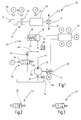
- Fig. 1 is shown in schematic form a drive train for a motor vehicle and generally designated 10.
- the powertrain 10 includes a drive motor 12 that may include an internal combustion engine or a hybrid drive unit.
- the drive train 10 has a coupling arrangement 14, which is connected on the input side to the drive motor 12.
- the clutch assembly 14 is connected to a stepped transmission 16, which may be formed, for example. In countershaft design.
- the stepped transmission 16 and the clutch assembly 14 may also be formed by a converter automatic transmission.
- An output of the step transmission 16 is connected to a differential 18, by means of which drive power is distributed to two driven wheels 20L, 20R.
- the clutch assembly 14 includes a friction clutch 22, which may be a dry clutch or a wet-running friction clutch, for example. In the form of a multi-plate clutch.
- the clutch assembly 14 has a hydraulic actuator assembly 24.
- the hydraulic actuator assembly 24 includes an electric motor 26 that drives a pump 28.
- the pump 28 has a suction port 30 and a pressure port 32.
- the suction port 30 is connected to a low-pressure region in the form of a tank 34.
- the pump 28 is shown as a unidirectional pump, but may also be a bidirectional pump.
- the electric motor 26 drives the pump 28 at a speed n.
- the actuator assembly 24 further includes a hydraulic cylinder 36, which in the present case is designed as a single-acting cylinder.
- the hydraulic cylinder 36 includes a piston 38 that is coupled to the friction clutch 22.
- the hydraulic cylinder 36 includes a piston spring 40, by means of which the piston 38 is biased into a position in which the friction clutch 22 assumes a basic position.
- the home position is an open position of the friction clutch 22, it may also be a closed position.
- a cylinder chamber 42 of the hydraulic cylinder 36 is connected via a pressure line 44 to the pressure port 32 of the pump 28.
- the connection between the pressure port 32 of the pump 28 and the cylinder chamber 42 is a direct connection, which in the present case should mean that no pressure control valve or the like is connected to the pressure line 44.
- the pressure of a hydraulic fluid in the pressure line 44 is rather adjusted by controlling the speed n of the electric motor 26.
- a hydraulic branch 48 is connected to the pressure line 44.
- the hydraulic branch 48 includes an orifice 50 and a valve 52 connected in series with the orifice 50.
- the hydraulic branch 48 is connected to the low-pressure region 34.
- the valve 52 is presently designed as a 2/2-way valve and has a valve spring 54, by means of which the valve 52 is biased into an open position in which the passage through the valve 52 is opened, as in Fig. 1 is shown.
- the valve 52 further includes an electrical actuator 56, for example.
- an electrical actuator 56 for example.
- the valve 52 can be placed in a closed position in which the hydraulic branch 48 is locked.
- the actuator 56 is connected to a controller 60 (connection A). To the pressure line 44, a pressure sensor 62 is connected, which is also connected to the control device 60.
- the actuator assembly 24 includes a temperature sensor 64 that measures the temperature of the hydraulic fluid.
- the temperature sensor 64 is connected in the region of the low-pressure region 34, but may also be connected to another location.
- the temperature sensor 64 detects the temperature of the hydraulic fluid and is connected to the controller 60 (port B).
- the powertrain 10 includes a number of sensors that can detect the operating condition of the clutch assembly 14 and / or other components of the powertrain.
- a motor sensor 66 connected to the control device 60 (connection C)
- a coupling sensor 68 connected to the control device 60 (connection D)
- a transmission sensor 70 connected to the control device 60 (connection e).
- the control device 60 detects at least one of the operating states and controls the valve 52 on the basis of the operating state in order to further limit the flow through the hydraulic branch as a function of the detected operating state, in particular to block the hydraulic branch 48.
- the general operation of the clutch assembly 14 is as follows. Starting from a basic state (assumed by way of example a normally open state, "normally open"), a higher-level control command for closing the friction clutch 22 is detected by the control device 60. The controller 60 then drives the electric motor 26 to drive the pump 28. As a result, hydraulic fluid is conveyed into the pressure line 44, where a pressure P builds up, which is detected by means of the pressure sensor 62. By controlling the rotational speed n of the electric motor 26, the pressure P can be sensitively adjusted. In this case, the hydraulic branch 48 assists by setting up a targeted leakage from the pressure line 44 to the low-pressure region 34 (the valve 52 is generally not actuated in this case, so that it does not limit the flow). As a result, the controllability of the pressure P can be improved, in particular with regard to the response behavior.
- valve 52 is actuated by the control device 60 to assume the second switching position (closed position) in which the flow through the hydraulic branch 48 is blocked.
- a certain operating state for example an increased temperature of the hydraulic fluid
- the valve 52 is actuated by the control device 60 to assume the second switching position (closed position) in which the flow through the hydraulic branch 48 is blocked.
- the valve 52 may be controlled by the controller 60 to assume the first shift position (open position) where the flow through the valve 52 is not obstructed.
- the pressure in the pressure line 44 can be rapidly reduced when the pump 28 is switched off, and also the fluid contained in the cylinder space 42 can be emptied relatively quickly via the orifice 50. By reversing the direction of rotation of the pump 28, this process can be further accelerated.
- valves are shown that replace valve 52 in FIG Fig. 1 can be used.
- valve 52 ' is identical in construction as the valve 52 of Fig. 1 with the exception that the orifice is integrated in the valve 52 'as shown in FIG Fig. 2 at 50 'is shown.
- Fig. 3 2 shows a valve 52 "in the form of a proportional or servo valve
- the flow through the valve 52 ' can be adjusted to any value between disabling the hydraulic branch 48 and fully opening the hydraulic branch 48.
- the valve 52 can be dispensed with the aperture 50 if necessary, since their function in the function of the valve 52" can be integrated.
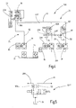
- a further embodiment of a clutch assembly 14A is shown, which generally with respect to structure and operation of the clutch assembly 14 of Fig. 1 equivalent.
- the same elements are therefore identified by the same reference numerals.
- the following section essentially explains the differences.
- the clutch assembly 14A has, in addition to the friction clutch 22, a further friction clutch 22A, whereby the clutch assembly 14A is suitable for use with a dual-clutch transmission of a motor vehicle drive train.
- the hydraulic actuator assembly 24 includes another electric motor 26A, another pump 28A, and another hydraulic cylinder 36A.
- the further Hydraulic cylinder 36A is connected via a further pressure line 44A to an unspecified pressure port of the further pump 28A.
- the further pressure line 44A is connected to the low-pressure region 34 via a further hydraulic branch 48A.
- a further aperture 50A is provided in the further hydraulic branch 48A.
- the actuator assembly 24 includes a fluid filter 74 connected between the low pressure region 34 and suction ports of the pumps 28, 28A.
- the temperature sensor 64 is connected.
- the clutch assembly 14A includes a cooling circuit 76 for the friction clutches 22, 22A.
- the cooling circuit 76 includes a cooling pump 78 driven by a cooling pump motor 80 in the form of an electric motor, and a pressure port of the cooling pump 78 is connected to a cooling section of the friction clutches 22, 22A via a cooling pipe 82.
- the two friction clutches 22 to 22A can be controlled independently of each other via the two parallel branches with the parallel pumps 28, 28A and the parallel pressure lines 44, 44A.
- each of the hydraulic branches 48, 48A one of the valves 52, 52 ', 52 "of the FIGS. 1 to 3 be used.
- valve 52 ' which is controlled by the control device 60 to further limit either the flow through the hydraulic branch 48 or the flow through the further hydraulic branch 48A.
- Fig. 5 shows an exemplary embodiment of such a valve 52 IV .
- the valve 52 IV is designed as a 4/4-way valve, the function of two-way valves 52 of Fig. 1 almost doubled. Since the functionality of the valve 52 IV is only necessary for the active branch, such a single valve for both hydraulic branches 48, 48 A can be realized.
Abstract
Kupplungsanordnung (14) für einen Kraftfahrzeugantriebsstrang (10), mit einer Reibkupplung (22) und einer hydraulischen Aktuatoranordnung (24) zum Betätigen der Reibkupplung (22), wobei die Aktuatoranordnung (24) einen Hydraulikzylinder (36), eine Pumpe (28) sowie einen Elektromotor (26) aufweist, wobei der Elektromotor (26) die Pumpe (28) antreibt, wobei ein Druckanschluss (32) der Pumpe (28) über eine Druckleitung (44) direkt mit dem Hydraulikzylinder (36) verbunden ist, wobei der von der Pumpe (28) in der Druckleitung (44) bereitgestellte Druck (P) durch Regeln der Drehzahl (n) des Elektromotors (26) einstellbar ist, wobei der Druckanschluss (32) über einen Hydraulikzweig (48) mit einem Niederdruckbereich (34) verbunden ist und wobei in dem Hydraulikzweig (48) eine den Durchfluss begrenzende Einrichtung (50) angeordnet ist. Dabei ist in dem Hydraulikzweig (48) ein Ventil (52) angeordnet, das dazu ansteuerbar ist, den Durchfluss durch den Hydraulikzweig (48) noch weiter zu begrenzen.A clutch arrangement (14) for a motor vehicle drive train (10), comprising a friction clutch (22) and a hydraulic actuator arrangement (24) for actuating the friction clutch (22), wherein the actuator arrangement (24) comprises a hydraulic cylinder (36), a pump (28) and an electric motor (26), wherein the electric motor (26) drives the pump (28), wherein a pressure port (32) of the pump (28) via a pressure line (44) is directly connected to the hydraulic cylinder (36), wherein the the pressure (P) provided in the pressure line (44) is adjustable by regulating the rotational speed (n) of the electric motor (26), the pressure port (32) being connected to a low-pressure region (34) via a hydraulic branch (48) and wherein in the hydraulic branch (48) a flow-limiting device (50) is arranged. In this case, a valve (52) is arranged in the hydraulic branch (48), which can be controlled to further limit the flow through the hydraulic branch (48).
Description
Die vorliegende Erfindung betrifft eine Kupplungsanordnung für einen Kraftfahrzeugantriebsstrang, mit einer Reibkupplung und einer hydraulischen Aktuatoranordnung zum Betätigen der Reibkupplung, wobei die Aktuatoranordnung einen Hydraulikzylinder, eine Pumpe sowie einen Elektromotor aufweist, wobei der Elektromotor die Pumpe antreibt, wobei ein Druckanschluss der Pumpe über eine Druckleitung direkt mit dem Hydraulikzylinder verbunden ist, wobei der von der Pumpe in der Druckleitung bereitgestellte Druck durch Regeln der Drehzahl des Elektromotors einstellbar ist, wobei der Druckanschluss über einen Hydraulikzweig mit einem Niederdruckbereich verbunden ist und wobei in dem Hydraulikzweig eine den Durchfluss begrenzende Einrichtung angeordnet ist.The present invention relates to a clutch assembly for a motor vehicle drive train, comprising a friction clutch and a hydraulic actuator assembly for actuating the friction clutch, wherein the actuator assembly comprises a hydraulic cylinder, a pump and an electric motor, wherein the electric motor drives the pump, wherein a pressure port of the pump via a pressure line is connected directly to the hydraulic cylinder, wherein the pressure provided by the pump in the pressure line by adjusting the speed of the electric motor is adjustable, wherein the pressure port is connected via a hydraulic branch with a low pressure region and wherein in the hydraulic branch, a flow restricting device is arranged.
Ferner betrifft die vorliegende Erfindung einen Antriebsstrang für ein Kraftfahrzeug mit einer solchen Kupplungsanordnung sowie ein Verfahren zum Ansteuern einer solchen Kupplungsanordnung.Furthermore, the present invention relates to a drive train for a motor vehicle with such a clutch assembly and a method for driving such a clutch assembly.
In Kraftfahrzeugantriebssträngen werden Kupplungsanordnungen der oben bezeichneten Art häufig als Anfahr- und Trennkupplungen verwendet. Dies kann sich sowohl auf automatisierte Schaltgetriebe mit einer einzelnen Reibkupplung als auch auf Doppelkupplungsgetriebe mit einer Kupplungsanordnung beziehen, die zwei derartige Reibkupplungen aufweist, die unabhängig voneinander ansteuerbar sind.In automotive drive trains, clutch assemblies of the type referred to above are often used as startup and disconnect clutches. This may relate both to automated manual transmissions with a single friction clutch and to dual clutch transmissions with a clutch arrangement having two such friction clutches which are independently controllable.
Es ist generell auch bekannt, derartige Reibkupplungen automatisiert mittels hydraulischer Aktuatoranordnungen zu betätigen.It is also generally known to actuate such friction clutches automatically by means of hydraulic actuator arrangements.
Bekannte Hydraulikkreise von hydraulischen Aktuatoranordnungen zur Betätigung von Reibkupplungen beinhalten generell eine Pumpe, die über einen Nebenantrieb eines Verbrennungsmotors oder über einen Elektromotor angetrieben wird. Dabei ist es bekannt, einen Leitungsdruck mittels eines Druckregelventils zu erzeugen. Aus dem Leitungsdruck wird dann ferner ein Betätigungsdruck abgeleitet, in der Regel mittels eines weiteren Druckregelventils. Derartige Druckregelventile werden als Proportional- oder Servoventile ausgeführt. Solche Ventile sind kostenaufwändig und haben den Nachteil, dass sie bei der Montage hohe Anforderungen hinsichtlich der Reinheit der Montageumgebung erfordern.Known hydraulic circuits of hydraulic actuator assemblies for actuating friction clutches generally include a pump that is driven via an auxiliary drive of an internal combustion engine or via an electric motor. It is known to generate a line pressure by means of a pressure control valve. From the line pressure then an operating pressure is further derived, usually by means of another pressure control valve. Such pressure control valves are designed as proportional or servo valves. Such valves are expensive and have the disadvantage that they require high demands on the mounting environment in the assembly process.
Aus dem Dokument
Die Schnellablassventile sind dabei so angesteuert, dass sie dann, wenn an dem einen Pumpenanschluss ein signifikanter Druck bereitgestellt wird, geschlossen werden.The quick-release valves are controlled so that they, when at the one pump port, a significant pressure is provided, are closed.
Eine weitere Möglichkeit einer hydraulischen Aktuatoranordnung beinhaltet einen sog. Pumpenaktuator. Hierbei ist eine Pumpe mit einem Elektromotor verbunden. Ein Druckanschluss der Pumpe ist über eine Druckleitung direkt mit einem Hydraulikzylinder zum Betätigen der Reibkupplung verbunden. Unter einer direkten Verbindung wird vorliegend insbesondere verstanden, dass in dieser Verbindung kein Druckregelventil vorhanden ist.Another possibility of a hydraulic actuator assembly includes a so-called pump actuator. Here, a pump is connected to an electric motor. A pressure port of the pump is connected via a pressure line directly to a hydraulic cylinder for actuating the friction clutch. In the present case, a direct connection is understood in particular to mean that no pressure regulating valve is present in this connection.
Der Druck in der Druckleitung zwischen Pumpe und Hydraulikzylinder wird durch Regeln der Drehzahl des Elektromotors eingestellt.The pressure in the pressure line between the pump and the hydraulic cylinder is adjusted by controlling the speed of the electric motor.
Zum Verbessern der Regelbarkeit ist es dabei bekannt, den Druckanschluss der Pumpe über einen Hydraulikzweig mit einem Niederdruckbereich zu verbinden.To improve the controllability, it is known to connect the pressure port of the pump via a hydraulic branch with a low pressure region.
Ein derartiger Pumpenaktuator ist bspw. aus dem Dokument
Aus diesem Dokument ist es ferner bekannt, die Druckleitung zwischen einem Druckanschluss der Pumpe und einem Hydraulikzylinder über ein Abführventil mit einem Reservoir zu verbinden, um einen besonders schnellen Druckabbau zu ermöglichen. Die Abführventile sind hier als elektronisch ansteuerbare Wegeventile dargestellt.From this document it is also known to connect the pressure line between a pressure port of the pump and a hydraulic cylinder via a discharge valve with a reservoir to allow a particularly rapid pressure reduction. The discharge valves are shown here as electronically controllable directional control valves.
Ferner sind an die Druckleitung Hydrospeicher angeschlossen, um Druck-/Volumen-Spitzen zu dämpfen.Furthermore, hydraulic accumulators are connected to the pressure line to dampen pressure / volume peaks.
Vor diesem Hintergrund ist es eine Aufgabe der Erfindung, eine verbesserte Kupplungsanordnung, ein verbessertes Ansteuerverfahren für eine Kupplungsanordnung sowie einen Antriebsstrang für ein Kraftfahrzeug mit einer solchen Kupplungsanordnung anzugeben, wobei die Kupplungsanordnung insbesondere besser an Betriebszustände der Kupplungsanordnung und/oder des Antriebsstranges angepasst werden kann, in den die Kupplungsanordnung integriert ist.Against this background, it is an object of the invention to provide an improved clutch assembly, an improved driving method for a clutch assembly and a drive train for a motor vehicle with such a clutch assembly, the clutch assembly can be particularly adapted to better operating conditions of the clutch assembly and / or the drive train, in which the clutch assembly is integrated.
Diese Aufgabe wird bei der eingangs genannten Kupplungsanordnung dadurch gelöst, dass in dem Hydraulikzweig ein Ventil angeordnet ist, das dazu ansteuerbar ist, den Durchfluss durch den Hydraulikzweig noch weiter zu begrenzen.This object is achieved in the aforementioned coupling arrangement in that in the hydraulic branch, a valve is arranged, which is controllable to limit the flow through the hydraulic branch even further.
Ferner wird die obige Aufgabe gelöst durch einen Antriebsstrang für ein Kraftfahrzeug mit einer erfindungsgemäßen Kupplungsanordnung.Furthermore, the above object is achieved by a drive train for a motor vehicle with a clutch assembly according to the invention.
Schließlich wird die obige Aufgabe gelöst durch ein Verfahren zum Ansteuern einer erfindungsgemäßen Kupplungsanordnung, mit den Schritten, wenigstens einen Betriebszustand der Kupplungsanordnung und/oder einen Betriebszustand des Antriebsstranges zu erfassen, in den die Kupplungsanordnung integriert ist, und das Ventil anzusteuern, um den Durchfluss durch den Hydraulikzweig in Abhängigkeit von dem erfassten Betriebszustand noch weiter zu begrenzen.Finally, the above object is achieved by a method for driving a clutch assembly according to the invention, with the steps to detect at least one operating state of the clutch assembly and / or an operating state of the drive train, in which the clutch assembly is integrated, and the valve to control the flow through to further limit the hydraulic branch as a function of the detected operating state.
Das Ventil ist vorzugsweise von einer Steuereinrichtung ansteuerbar. Die Steuereinrichtung kann Betriebszustände der Kupplungsanordnung und/oder anderer Komponenten des Antriebsstranges erfassen, um auf dieser Grundlage das Ventil anzusteuern. Das Ventil ist vorzugsweise - logisch gesehen - in Reihe geschaltet mit der den Durchfluss begrenzenden Einrichtung. Dies impliziert vorzugsweise, dass der Volumenstrom durch den Hydraulikzweig generell auf einen Wert begrenzt ist, der durch die den Durchfluss begrenzende Einrichtung festgelegt ist. Bei der den Durchfluss begrenzenden Einrichtung kann es sich hier insbesondere um eine Blende handeln.The valve is preferably controllable by a control device. The controller may detect operating conditions of the clutch assembly and / or other components of the drive train to control the valve based thereon. The valve is preferably - logically - in series with the flow restricting device. This preferably implies that the volume flow through the hydraulic branch is generally limited to a value set by the flow restricting device. The flow-restricting device may in particular be a diaphragm.
Das Ventil ist bei einer - logisch gesehen - seriellen Anordnung mit einer solchen Einrichtung dazu ausgebildet, den begrenzten Volumenstrom bedarfsweise noch weiter zu begrenzen.The valve is formed in a - logically - serial arrangement with such a device to limit the limited volume flow, if necessary, even further.
Durch diese Ausgestaltung kann der Leckagestrom, der generell für eine verbesserte Regelbarkeit sorgt, an Betriebszustände angepasst werden. Die Betriebszustände können eine Temperatur eines Hydraulikfluides, eine Boost-Phase des Antriebsstranges, eine Start-Stopp-Phase des Antriebsstranges, eine hohe Druckanforderung in der Druckleitung und/oder einen Notfall- oder Störzustand der Kupplungsanordnung und/oder des Antriebsstranges beinhalten.With this configuration, the leakage current, which generally provides for improved controllability, can be adapted to operating conditions. The operating conditions may include a temperature of a hydraulic fluid, a boost phase of the powertrain, a start-stop phase of the powertrain, a high pressure request in the pressure line, and / or an emergency or fault condition of the clutch assembly and / or powertrain.
Insbesondere ist es bevorzugt, wenn das Ventil betätigt wird, um den Durchfluss durch den Hydraulikzweig noch weiter zu begrenzen, wenn die Temperatur des Hydraulikfluides einen Schwellenwert überschreitet. Denn bei sehr warmen Hydraulikfluiden kann hierdurch erreicht werden, dass trotz des warmen Hydraulikfluids erforderliche hohe Kupplungsdrücke immer realisiert werden können. Ferner kann der Pumpenantrieb kompakter dimensioniert werden.In particular, it is preferred that the valve is actuated to further limit flow through the hydraulic branch when the temperature of the hydraulic fluid exceeds a threshold. Because with very warm hydraulic fluids can be achieved in this way that despite the warm hydraulic fluid required high clutch pressures can always be realized. Furthermore, the pump drive can be made more compact.
Schließlich kann die erfindungsgemäße Kupplungsanordnung auch dazu verwendet werden, um den Energieverbrauch der Kupplungsanordnung zu verringern. Durch den im Stand der Technik unveränderlichen ständigen Abfluss über den Hydraulikzweig wird es notwendig, die Pumpe auch im stationären Betrieb, bspw. in einem Start-Stopp-Zustand oder Ähnliches ständig anzutreiben, um den jeweiligen Druck zu halten. Durch Ansteuern des Ventils derart, dass der Durchfluss noch weiter begrenzt wird, kann der Wirkungsgrad der Kupplungsanordnung folglich verbessert werden.Finally, the clutch assembly according to the invention can also be used to reduce the power consumption of the clutch assembly. Due to the constant flow in the prior art over the hydraulic branch, it is necessary to constantly drive the pump in stationary operation, for example. In a start-stop state or the like, in order to maintain the respective pressure. By driving the valve so that the flow is further limited, the efficiency of the clutch assembly can thus be improved.
Das Ventil kann insbesondere dazu ansteuerbar sein, den Durchfluss durch den Hydraulikzweig vollständig zu sperren. Hierdurch kann bei bestimmten Betriebszuständen der Energieverbrauch der Kupplungsanordnung signifikant reduziert werden.The valve can in particular be controlled to completely block the flow through the hydraulic branch. As a result, the energy consumption of the clutch assembly can be significantly reduced in certain operating conditions.
Über eine Ansteuerung des Ventils ist es generell auch möglich, ein verändertes Druckansprechverhalten (Druckaufbau und -abbau) aufgrund schwankender Hydraulikfluidtemperatur zu kompensieren.By controlling the valve, it is generally also possible to compensate for a changed pressure response (pressure build-up and release) due to fluctuating hydraulic fluid temperature.
Die hydraulische Aktuatoranordnung weist in der Druckleitung vorzugsweise kein Druckregelventil auf, insbesondere kein proportionales Druckregelventil.The hydraulic actuator assembly preferably has no pressure control valve in the pressure line, in particular no proportional pressure control valve.
Hierdurch ist es auch möglich, die Kupplungsanordnung bei geringen Anforderungen an die Reinheit während der Montage zu fertigen.This also makes it possible to manufacture the clutch assembly with low requirements for the purity during assembly.
Die Aufgabe wird somit vollkommen gelöst.The task is thus completely solved.
Von besonderem Vorzug ist es, wenn das Ventil in dem Hydraulikzweig als Wegeventil ausgebildet ist, das eine Schaltposition aufweist, in der der Hydraulikzweig gesperrt ist.It is of particular advantage if the valve in the hydraulic branch is designed as a directional control valve, which has a switching position in which the hydraulic branch is blocked.
Das Wegeventil ist dabei vorzugsweise als herkömmliches Wegeventil ausgebildet, das gerade nicht als Proportional- oder Servoventil ausgebildet ist. Hierdurch kann das Ventil bei vergleichsweise geringen Anforderungen an die Reinheit während der Montage in die Kupplungsanordnung integriert werden.The directional control valve is preferably designed as a conventional directional control valve, which is currently not designed as a proportional or servo valve. As a result, the valve can be integrated into the coupling arrangement with comparatively low demands on the purity during assembly.
Das Wegeventil ist vorzugsweise seriell mit der den Durchfluss begrenzenden Einrichtung in dem Hydraulikzweig verbunden. Das Wegeventil kann in eine Schaltposition vorgespannt sein, bei der das Wegeventil vollständig geöffnet ist, so dass der Durchfluss durch den Hydraulikzweig alleine durch die den Durchfluss begrenzende Einrichtung begrenzt wird. Das Wegeventil kann über eine Steuereinrichtung elektrisch ansteuerbar sein (bspw. mittels eines Magnetaktuators), um das Wegeventil in die Schaltposition zu versetzen, in der der Hydraulikzweig gesperrt ist.The directional control valve is preferably connected in series with the flow restricting device in the hydraulic branch. The directional control valve may be biased to a shift position in which the directional control valve is fully open, such that flow through the hydraulic branch is limited solely by the flow restricting device. The directional control valve can electrically via a control device be controllable (for example by means of a solenoid actuator) to enable the directional control valve in the switching position in which the hydraulic branch is locked.
Insgesamt ist es ferner vorteilhaft, wenn die den den Durchfluss begrenzende Einrichtung eine Blende ist.Overall, it is also advantageous if the flow restricting device is a diaphragm.
Hierdurch kann die den Durchfluss begrenzende Einrichtung kostengünstig realisiert werden.As a result, the flow restricting device can be realized inexpensively.
Die Blende kann dabei als separates Bauteil ausgebildet sein, das seriell vor oder hinter dem Ventil in dem Hydraulikzweig angeordnet ist.The diaphragm can be designed as a separate component, which is arranged in series in front of or behind the valve in the hydraulic branch.
In einer bevorzugten Variante ist die Blende in das Ventil integriert.In a preferred variant, the diaphragm is integrated in the valve.
Generell ist es auch denkbar, das Ventil als Servoventil oder als Proportionalventil auszubilden. Derartige Ventile ermöglichen in der Regel eine Einstellung des Durchflusses durch den Hydraulikzweig von einem vollkommen gesperrten Zustand in einen vollkommen geöffneten Zustand, mit allen möglichen Zwischenwerten.In general, it is also conceivable to design the valve as a servo valve or as a proportional valve. Such valves typically permit adjustment of the flow through the hydraulic branch from a fully locked condition to a fully open condition, with all possible intermediate values.
Mittels eines Servo- oder Proportionalventils kann folglich der Durchfluss durch den Hydraulikzweig bedarfsweise geregelt werden.By means of a servo or proportional valve, consequently, the flow through the hydraulic branch can be regulated as required.
In diesem Fall ist eine separate, dem Durchfluss begrenzende Einrichtung nicht notwendig, da diese durch die Funktion des Servoventils bzw. des Proportionalventils nachgebildet werden kann.In this case, a separate, the flow restricting device is not necessary, since this can be simulated by the function of the servo valve or the proportional valve.
Die Kupplungsanordnung kann für einen Antriebsstrang vorgesehen sein, bei dem zwischen einem Antriebsmotor und einem Stufengetriebe nur die einzelne Reibkupplung vorgesehen ist.The clutch assembly may be provided for a powertrain in which only the single friction clutch is provided between a drive motor and a stepped transmission.
Gemäß einer weiteren bevorzugten Ausführungsform beinhaltet die Kupplungsanordnung eine weitere Reibkupplung, wobei die hydraulische Aktuatoranordnung auch zum Betätigen der weiteren Reibkupplung ausgelegt ist, wobei die Aktuatoranordnung einen weiteren Hydraulikzylinder, eine weitere Pumpe sowie einen weiteren Elektromotor aufweist, wobei der weitere Elektromotor die weitere Pumpe antreibt, wobei ein Druckanschluss der weiteren Pumpe über eine weitere Druckleitung direkt mit dem weiteren Hydraulikzylinder verbunden ist, wobei der Druckanschluss der weiteren Pumpe über einen weiteren Hydraulikzweig mit dem Niederdruckbereich verbunden ist und wobei in dem weiteren Hydraulikzweig eine weitere den Durchfluss begrenzende Einrichtung angeordnet ist.According to a further preferred embodiment, the clutch assembly includes a further friction clutch, wherein the hydraulic actuator assembly is also designed to actuate the further friction clutch, wherein the actuator assembly comprises a further hydraulic cylinder, another pump and a further electric motor, wherein the further electric motor drives the further pump, wherein a pressure port of the further pump via a further pressure line directly connected to the further hydraulic cylinder is, wherein the pressure port of the further pump is connected via a further hydraulic branch to the low-pressure region and wherein in the further hydraulic branch, a further flow-limiting device is arranged.
Eine derartige Kupplungsanordnung eignet sich insbesondere für Antriebsstränge mit Doppelkupplungsgetriebe.Such a clutch arrangement is particularly suitable for drive trains with dual-clutch transmission.
Durch das Bereitstellen von separaten Pumpen und Elektromotoren ist es möglich, die zwei Reibkupplungen vollkommen unabhängig voneinander anzusteuern, so dass sich insbesondere gegenüber dem eingangs erwähnten Stand der Technik eine erhöhte Flexibilität bei der Ansteuerung ergibt.By providing separate pumps and electric motors, it is possible to control the two friction clutches completely independently of one another, so that, in particular compared to the prior art mentioned at the beginning, increased flexibility results in the control.
Hierbei versteht sich, dass in dem weiteren Hydraulikzweig ein weiteres Ventil angeordnet sein kann, das dazu ansteuerbar ist, den Durchfluss durch den weiteren Hydraulikzweig noch weiter zu begrenzen.It is understood that in the further hydraulic branch, a further valve may be arranged, which is controllable to further limit the flow through the further hydraulic branch.
In einer bevorzugten Ausführungsform ist dabei dem Hydraulikzweig und dem weiteren Hydraulikzweig ein einzelnes Ventil zugeordnet, das dazu ansteuerbar ist, entweder den Durchfluss durch den Hydraulikzweig oder den Durchfluss durch den weiteren Hydraulikzweig noch weiter zu begrenzen.In a preferred embodiment, a single valve is assigned to the hydraulic branch and the further hydraulic branch, which can be controlled to further limit either the flow through the hydraulic branch or the flow through the further hydraulic branch.
Ein derartiges Ventil, das beiden Hydraulikzweigen zugeordnet ist, kann ebenfalls als Wegeventil ausgebildet sein, kann jedoch auch als Servo- oder Proportionalventil ausgebildet sein.Such a valve, which is associated with two hydraulic branches, may also be designed as a directional control valve, but may also be designed as a servo or proportional valve.
Ferner ist es insgesamt vorteilhaft, wenn das Ventil von einer Steuereinrichtung ansteuerbar ist, die dazu ausgebildet ist, das Ventil bedarfsweise in Abhängigkeit von wenigstens einem Betriebszustand dazu anzusteuern, den Durchfluss durch den Hydraulikzweig noch weiter zu begrenzen.Furthermore, it is altogether advantageous if the valve can be actuated by a control device which is designed to operate the valve as required of at least one operating state to control to limit the flow through the hydraulic branch even further.
Die bedarfsweise Ansteuerung kann im einfachsten Fall dazu eingerichtet sein, das Ventil in dem jeweiligen Hydraulikzweig dazu ansteuern, den Durchfluss noch weiter zu begrenzen, wenn die Temperatur des Hydraulikfluides einen Schwellenwert überschreitet, wenn das Hydraulikfluid also relativ warm ist.In the simplest case, the activation as required can be set up to actuate the valve in the respective hydraulic branch to limit the flow even further when the temperature of the hydraulic fluid exceeds a threshold value, ie when the hydraulic fluid is relatively warm.
Generell ist es auch denkbar, die den Durchfluss begrenzende Einrichtung (z.B. Blende) aufgrund der Möglichkeit der weiteren Begrenzung des Durchflusses größer auszulegen, so dass bei nicht angesteuertem Ventil ein relativ großer Durchfluss durch den weiteren Hydraulikzweig ermöglicht wird. Hierdurch kann die Regelbarkeit ggf. noch verbessert werden. Ferner kann auch ggf. ein schnellerer Druckabbau ermöglicht werden, wobei es vorzugsweise in diesem Fall nicht notwendig ist, für einen schnellen Druckabbau separate Abführventile vorzusehen.In general, it is also conceivable to make the flow-restricting device (for example diaphragm) larger due to the possibility of further limitation of the flow, so that a relatively large flow through the further hydraulic branch is made possible when the valve is not actuated. As a result, the controllability can be improved if necessary. Furthermore, a faster pressure reduction may possibly also be made possible, wherein it is preferably not necessary in this case to provide separate exhaust valves for rapid pressure reduction.
Das Ventil wird bei niedrigen Temperaturen des Hydraulikfluides vorzugsweise nicht angesteuert, so dass der Durchfluss durch den Hydraulikzweig allein durch die den Durchfluss begrenzende Einrichtung begrenzt ist.The valve is preferably not actuated at low temperatures of the hydraulic fluid, so that the flow through the hydraulic branch is limited solely by the flow restricting device.
Während sog. Boost-Phasen kann das Ventil angesteuert werden, um ein schnelles Füllen der Kupplung zu ermöglichen. Am Ende der Boost-Phase kann das Ventil hingegen wieder geöffnet werden, um Druckspitzen zu dämpfen.During so-called boost phases, the valve can be activated to allow a quick filling of the clutch. At the end of the boost phase, however, the valve can be reopened to dampen pressure spikes.
Das Ventil kann dazu angesteuert werden, den Durchfluss weiter zu begrenzen, wenn eine Start-Stopp-Phase in dem Antriebsstrang eingerichtet ist, wodurch der Wirkungsgrad verbessert werden kann. Ein Entleeren einer Kupplungssteuerschaltung kann hierdurch vorzugsweise verhindert werden. Ferner können vorzugsweise NVH-Probleme während einer Phase, bei der der Verbrennungsmotor angehalten ist, vermieden werden, da die Pumpe vorzugsweise während dieser Phase nicht in Drehung versetzt werden muss. Schließlich kann für diesen Fall auch elektrische Leistung eingespart werden.The valve may be controlled to further limit the flow when a start-stop phase is established in the driveline, whereby the efficiency may be improved. Discharging a clutch control circuit can thereby be preferably prevented. Further, NVH problems may preferably be avoided during a phase in which the engine is stopped because the pump preferably does not need to be rotated during this phase. Finally, electrical power can be saved for this case.
Bei hohen Druckanforderungen kann das Ventil ebenfalls angesteuert werden, um eine hohe Druckverfügbarkeit zu ermöglichen.For high pressure requirements, the valve can also be controlled to allow high pressure availability.
Schließlich kann das Ventil gezielt geöffnet werden, wenn ein Notfalloder Störzustand auftritt, um die Kupplung so schnell wie möglich zu öffnen, ohne Einschränkungen aufgrund eines niedrigen Druckes oder aufgrund einer niedrigen Temperatur.Finally, the valve can be selectively opened when an emergency condition occurs to open the clutch as quickly as possible, with no restrictions due to low pressure or low temperature.
Es versteht sich, dass die vorstehend genannten und die nachstehend noch zu erläuternden Merkmale nicht nur in der jeweils angegebenen Kombination, sondern auch in anderen Kombinationen oder in Alleinstellung verwendbar sind, ohne den Rahmen der vorliegenden Erfindung zu verlassen.It is understood that the features mentioned above and those yet to be explained below can be used not only in the particular combination given, but also in other combinations or in isolation, without departing from the scope of the present invention.
Ausführungsbeispiele der Erfindung sind in der Zeichnung dargestellt und werden in der nachfolgenden Beschreibung näher erläutert. Es zeigen:
- Fig. 1
- eine schematische Ansicht eines Antriebsstranges für ein Kraftfahrzeug mit einer Ausführungsform einer erfindungsgemäßen Kupplungsanordnung;
- Fig. 2
- eine alternative Ausführungsform eines Ventils für die Kupplungsanordnung der
Fig. 1 ; - Fig. 3
- eine alternative Ausführungsform eines Ventils für die Kupplungsanordnung der
Fig. 1 ; - Fig. 4
- eine weitere schematische Darstellung einer Ausführungsform einer erfindungsgemäßen Kupplungsanordnung mit zwei Reibkupplungen und einem gemeinsamen Ventil für zwei Hydraulikzweige; und
- Fig. 5
- eine schematische Darstellung einer Ausführungsform eines derartigen gemeinsamen Ventils für die Kupplungsanordnung der
Fig. 4
- Fig. 1
- a schematic view of a drive train for a motor vehicle with an embodiment of a clutch assembly according to the invention;
- Fig. 2
- an alternative embodiment of a valve for the clutch assembly of
Fig. 1 ; - Fig. 3
- an alternative embodiment of a valve for the clutch assembly of
Fig. 1 ; - Fig. 4
- a further schematic representation of an embodiment of a clutch assembly according to the invention with two friction clutches and a common valve for two hydraulic branches; and
- Fig. 5
- a schematic representation of an embodiment of such a common valve for the clutch assembly of
Fig. 4
In
Das Stufengetriebe 16 und die Kupplungsanordnung 14 können auch durch ein Wandler-Automatikgetriebe gebildet sein.The stepped
Ein Ausgang des Stufengetriebe 16 ist mit einem Differential 18 verbunden, mittels dessen Antriebsleistung auf zwei angetriebene Räder 20L, 20R verteilt wird.An output of the
Die Kupplungsanordnung 14 beinhaltet eine Reibkupplung 22, bei der es sich um Trockenkupplung oder um eine nasslaufende Reibkupplung, bspw. in Form einer Lamellenkupplung handeln kann.The
Ferner weist die Kupplungsanordnung 14 eine hydraulische Aktuatoranordnung 24 auf. Die hydraulische Aktuatoranordnung 24 weist einen Elektromotor 26 auf, der eine Pumpe 28 antreibt. Die Pumpe 28 weist einen Sauganschluss 30 und einen Druckanschluss 32 auf. Der Sauganschluss 30 ist mit einem Niederdruckbereich in Form eines Tanks 34 verbunden. Die Pumpe 28 ist als unidirektionale Pumpe dargestellt, kann jedoch auch eine bidirektionale Pumpe sein. Der Elektromotor 26 treibt die Pumpe 28 mit einer Drehzahl n an.Furthermore, the
Die Aktuatoranordnung 24 beinhaltet ferner einen Hydraulikzylinder 36, der vorliegend als einfach wirkender Zylinder ausgebildet ist. Der Hydraulikzylinder 36 beinhaltet einen Kolben 38, der mit der Reibkupplung 22 gekoppelt ist. Ferner beinhaltet der Hydraulikzylinder 36 eine Kolbenfeder 40, mittels der der Kolben 38 in eine Position vorgespannt ist, bei der die Reibkupplung 22 eine Grundposition einnimmt. In der Regel ist die Grundposition eine offene Position der Reibkupplung 22 kann jedoch auch eine geschlossene Position sein.The
Ein Zylinderraum 42 des Hydraulikzylinders 36 ist über eine Druckleitung 44 mit dem Druckanschluss 32 der Pumpe 28 verbunden. Die Verbindung zwischen dem Druckanschluss 32 der Pumpe 28 und dem Zylinderraum 42 ist eine direkte Verbindung, was vorliegend heißen soll, dass an die Druckleitung 44 kein Druckregelventil oder dergleichen angeschlossen ist. Der Druck eines Hydraulikfluids in der Druckleitung 44 wird vielmehr durch Regeln der Drehzahl n des Elektromotors 26 eingestellt.A
An die Druckleitung 44 ist ein Hydraulikzweig 48 angeschlossen. Der Hydraulikzweig 48 beinhaltet eine Blende 50 und ein Ventil 52, das in Reihe mit der Blende 50 geschaltet ist. Der Hydraulikzweig 48 ist mit dem Niederdruckbereich 34 verbunden.To the
Das Ventil 52 ist vorliegend als 2/2-Wegeventil ausgebildet und weist eine Ventilfeder 54 auf, mittels der das Ventil 52 in eine Offenposition vorgespannt ist, bei der der Durchgang durch das Ventil 52 geöffnet ist, wie es in
Das Ventil 52 weist ferner ein elektrisches Betätigungselement 56, bspw. in Form eines Magnetaktuators, auf, mittels dessen das Ventil 52 in eine Schließposition versetzt werden kann, bei der der Hydraulikzweig 48 gesperrt ist.The
Das Betätigungselement 56 ist mit einer Steuereinrichtung 60 verbunden (Verbindung A). An die Druckleitung 44 ist ein Drucksensor 62 angeschlossen, der ebenfalls mit der Steuereinrichtung 60 verbunden ist.The
Ferner weist die Aktuatoranordnung 24 einen Temperatursensor 64 auf, der die Temperatur des Hydraulikfluides misst. Vorliegend ist der Temperatursensor 64 im Bereich des Niederdruckbereiches 34 angeschlossen, kann jedoch auch an einer anderen Stelle angeschlossen sein. Der Temperatursensor 64 erfasst die Temperatur des Hydraulikfluides und ist mit der Steuereinrichtung 60 verbunden (Anschluss B).Furthermore, the
Ferner beinhaltet der Antriebsstrang 10 eine Reihe von Sensoren, die den Betriebszustand der Kupplungsanordnung 14 und/oder von anderen Komponenten des Antriebsstranges erfassen können. Beispielhaft sind vorliegend ein Motorsensor 66 gezeigt, der mit der Steuereinrichtung 60 verbunden ist (Anschluss C), ein Kupplungssensor 68, der mit der Steuereinrichtung 60 verbunden ist (Anschluss D), und ein Getriebesensor 70, der mit der Steuereinrichtung 60 verbunden ist (Anschluss E).Further, the
Die Steuereinrichtung 60 erfasst wenigstens einen der Betriebszustände und steuert das Ventil 52 auf der Grundlage des Betriebszustandes, um den Durchfluss durch den Hydraulikzweig in Abhängigkeit von dem erfassten Betriebszustand noch weiter zu begrenzen, insbesondere den Hydraulikzweig 48 zu sperren.The
Die generelle Funktionsweise der Kupplungsanordnung 14 ist Folgende. Ausgehend von einem Grundzustand (beispielhaft angenommen ein normalerweise geöffneter Zustand, "normally open") wird ein übergeordneter Steuerbefehl zum Schließen der Reibkupplung 22 von der Steuereinrichtung 60 erfasst. Die Steuereinrichtung 60 steuert daraufhin den Elektromotor 26 an, um die Pumpe 28 anzutreiben. Hierdurch wird Hydraulikfluid in die Druckleitung 44 gefördert, wo sich ein Druck P aufbaut, der mittels des Drucksensors 62 erfasst wird. Durch Regeln der Drehzahl n des Elektromotors 26 lässt sich der Druck P feinfühlig einstellen. Hierbei unterstützt der Hydraulikzweig 48, indem eine gezielte Leckage von der Druckleitung 44 hin zu dem Niederdruckbereich 34 eingerichtet wird (das Ventil 52 ist dabei in der Regel nicht angesteuert, so dass es den Durchfluss nicht begrenzt). Hierdurch kann die Regelbarkeit des Druckes P verbessert werden, insbesondere hinsichtlich des Ansprechverhaltens.The general operation of the
Sofern ein bestimmter Betriebszustand erfasst wird, bspw. eine erhöhte Temperatur des Hydraulikfluides, wird das Ventil 52 von der Steuereinrichtung 60 dazu angesteuert, die zweite Schaltposition (Schließposition) einzunehmen, bei der der Durchfluss durch den Hydraulikzweig 48 gesperrt ist. Hierdurch kann in bestimmten Betriebszuständen ein schnellerer Druckaufbau erreicht werden bzw. ein geringerer Energieverbrauch bzw. die Erfüllung hoher Druckanforderungen.If a certain operating state is detected, for example an increased temperature of the hydraulic fluid, the
In einem Notfall- oder Störzustand kann das Ventil 52 von der Steuereinrichtung 60 dazu angesteuert werden, die erste Schaltposition (Offenposition) einzunehmen, bei der der Durchfluss durch das Ventil 52 nicht behindert ist. Hierdurch kann der Druck in der Druckleitung 44 bei abgeschalteter Pumpe 28 schnell abgebaut werden, und auch das in dem Zylinderraum 42 enthaltene Fluid kann vergleichsweise schnell über die Blende 50 entleert werden. Durch Umkehren der Drehrichtung der Pumpe 28 lässt sich dieser Vorgang noch weiter beschleunigen.In an emergency or fault condition, the
In den
Das in
In
Die Kupplungsanordnung 14A weist neben der Reibkupplung 22 eine weitere Reibkupplung 22A auf, wodurch sich die Kupplungsanordnung 14A zur Verwendung einem Doppelkupplungsgetriebe eines Kraftfahrzeugantriebsstranges eignet. Demzufolge beinhaltet die hydraulische Aktuatoranordnung 24 einen weiteren Elektromotor 26A, eine weitere Pumpe 28A und einen weiteren Hydraulikzylinder 36A. Der weitere Hydraulikzylinder 36A ist über eine weitere Druckleitung 44A mit einem nicht näher bezeichneten Druckanschluss der weiteren Pumpe 28A verbunden. Die weitere Druckleitung 44A ist über einen weiteren Hydraulikzweig 48A mit dem Niederdruckbereich 34 verbunden. In dem weiteren Hydraulikzweig 48A ist eine weitere Blende 50A vorgesehen.The
Ferner beinhaltet die Aktuatoranordnung 24 einen Fluidfilter 74, der zwischen den Niederdruckbereich 34 und Sauganschlüsse der Pumpen 28, 28A geschaltet ist. Hier ist auch der Temperatursensor 64 angeschlossen.Furthermore, the
Zudem beinhaltet die Kupplungsanordnung 14A einen Kühlkreis 76 für die Reibkupplungen 22, 22A. Der Kühlkreis 76 beinhaltet eine Kühlpumpe 78, die mittels eines Kühlpumpenmotors 80 in Form eines Elektromotors angetrieben ist, wobei ein Druckanschluss der Kühlpumpe 78 über eine Kühlleitung 82 mit einem Kühlabschnitt der Reibkupplungen 22, 22A verbunden ist.In addition, the
Die zwei Reibkupplungen 22 bis 22A lassen sich über die zwei parallelen Zweige mit den parallelen Pumpen 28, 28A und den parallelen Druckleitungen 44, 44A unabhängig voneinander ansteuern.The two
Generell kann in jedem der Hydraulikzweige 48, 48A eines der Ventile 52, 52', 52" der
Vorliegend ist dargestellt, dass eine solche Anordnung aus zwei Ventilen durch ein einzelnes Ventil 52'" ersetzt werden kann, das von der Steuereinrichtung 60 dazu angesteuert wird, entweder den Durchfluss durch den Hydraulikzweig 48 oder den Durchfluss durch den weiteren Hydraulikzweig 48A weiter zu begrenzen.In the present case, it is shown that such an arrangement of two valves can be replaced by a single valve 52 '"which is controlled by the
Claims (11)
dadurch gekennzeichnet, dass
in dem Hydraulikzweig (48) ein Ventil (52) angeordnet ist, das dazu ansteuerbar ist, den Durchfluss durch den Hydraulikzweig (48) noch weiter zu begrenzen.A clutch arrangement (14) for a motor vehicle drive train (10), comprising a friction clutch (22) and a hydraulic actuator arrangement (24) for actuating the friction clutch (22), wherein the actuator arrangement (24) comprises a hydraulic cylinder (36), a pump (28) and an electric motor (26), wherein the electric motor (26) drives the pump (28), wherein a pressure port (32) of the pump (28) via a pressure line (44) is directly connected to the hydraulic cylinder (36), wherein the the pressure (P) provided in the pressure line (44) is adjustable by regulating the rotational speed (n) of the electric motor (26), the pressure port (32) being connected to a low-pressure region (34) via a hydraulic branch (48) and wherein in the hydraulic branch (48) a flow-restricting device (50) is arranged,
characterized in that
in the hydraulic branch (48) a valve (52) is arranged, which is controllable to limit the flow through the hydraulic branch (48) even further.
Applications Claiming Priority (1)
| Application Number | Priority Date | Filing Date | Title |
|---|---|---|---|
| DE102014102250.5A DE102014102250A1 (en) | 2014-02-21 | 2014-02-21 | Clutch assembly, automotive powertrain and clutch control method |
Publications (3)
| Publication Number | Publication Date |
|---|---|
| EP2924312A2 true EP2924312A2 (en) | 2015-09-30 |
| EP2924312A3 EP2924312A3 (en) | 2016-05-11 |
| EP2924312B1 EP2924312B1 (en) | 2018-03-28 |
Family
ID=52358622
Family Applications (1)
| Application Number | Title | Priority Date | Filing Date |
|---|---|---|---|
| EP15150874.4A Active EP2924312B1 (en) | 2014-02-21 | 2015-01-13 | Coupling assembly, motor vehicle power train and coupling control method |
Country Status (3)
| Country | Link |
|---|---|
| EP (1) | EP2924312B1 (en) |
| CN (1) | CN104863991A (en) |
| DE (1) | DE102014102250A1 (en) |
Families Citing this family (8)
| Publication number | Priority date | Publication date | Assignee | Title |
|---|---|---|---|---|
| DE102014105168A1 (en) * | 2014-04-11 | 2015-10-15 | Getrag Getriebe- Und Zahnradfabrik Hermann Hagenmeyer Gmbh & Cie Kg | Clutch assembly, powertrain and clutch actuation method |
| CN106763285A (en) * | 2016-12-27 | 2017-05-31 | 湘潭大学 | The control device and control method of multi-disc wet clutch coefficient of friction compensating for loss and damage |
| IT201800001757A1 (en) * | 2018-01-24 | 2019-07-24 | Magneti Marelli Spa | HYDRAULICALLY SERVO-ASSISTED TRANSMISSION WITH PRESSURE CONTROL OF THE ROTATION SPEED OF THE ELECTRIC MOTORS THAT DRIVE THE PUMPS |
| DE102018204084A1 (en) * | 2018-03-16 | 2019-09-19 | GETRAG B.V. & Co. KG | Actuator and cooling arrangement for a transmission |
| DE102018107973A1 (en) | 2018-04-05 | 2019-10-10 | Schaeffler Technologies AG & Co. KG | Clutch actuation system |
| DE102019106895A1 (en) * | 2019-03-19 | 2020-09-24 | Schaeffler Technologies AG & Co. KG | Method for controlling a hydraulic pump and method for operating a clutch and / or transmission device |
| WO2021223799A1 (en) * | 2020-05-04 | 2021-11-11 | Schaeffler Technologies AG & Co. KG | Method for improving the sealing tightness of a valve in a hydraulic circuit of a clutch actuation system |
| CN117109957B (en) * | 2023-07-06 | 2024-03-26 | 中国人民解放军63921部队 | Intelligent detection system for rocket bracket distributed electro-hydraulic actuator |
Citations (2)
| Publication number | Priority date | Publication date | Assignee | Title |
|---|---|---|---|---|
| EP1236918B1 (en) | 2001-02-22 | 2003-10-15 | ZF Sachs AG | Clutch system with a pump actuated clutch |
| WO2006002450A1 (en) | 2004-06-30 | 2006-01-12 | Magna Drivetrain Ag & Co Kg | Hydraulic system for controlling two clutches of a transmission |
Family Cites Families (11)
| Publication number | Priority date | Publication date | Assignee | Title |
|---|---|---|---|---|
| DE19633420A1 (en) * | 1995-09-15 | 1997-03-20 | Ebern Fahrzeugtech Gmbh | Clutch control system particularly for motor vehicle |
| JP2001206092A (en) * | 2000-01-24 | 2001-07-31 | Fuji Univance Corp | Driving force distribution device |
| JP3851108B2 (en) * | 2001-05-07 | 2006-11-29 | 株式会社ユニバンス | Driving force distribution device |
| AT6575U1 (en) * | 2002-10-31 | 2003-12-29 | Magna Steyr Powertrain Ag & Co | SIMPLE ACTING ACTUATOR WITH QUICK-OPENING HYDRAULIC VALVE FOR CONTROLLING A CLUTCH |
| AU2003294821A1 (en) * | 2003-12-09 | 2005-07-21 | Gkn Driveline International Gmbh | Hydraulic system for two multiplate clutches |
| DE102005014654B4 (en) * | 2005-03-31 | 2014-03-06 | Gkn Driveline International Gmbh | Motor vehicle hydraulic pump |
| US8900086B2 (en) * | 2007-08-02 | 2014-12-02 | Honda Motor Co., Ltd. | Hydraulic vehicle clutch system, drivetrain for a vehicle including same, and method |
| DE102007044431A1 (en) * | 2007-09-18 | 2009-03-19 | Zf Friedrichshafen Ag | Electrohydraulic control device |
| US8052578B2 (en) * | 2008-05-30 | 2011-11-08 | Honda Motor Co., Ltd. | Hydraulic vehicle clutch system and preemptive control method |
| DE102011105648A1 (en) * | 2011-06-07 | 2012-12-13 | Fte Automotive Gmbh | Hydraulic actuator for the actuation of clutches in particular a multi-clutch transmission for motor vehicles |
| DE102013200484A1 (en) * | 2012-01-24 | 2013-07-25 | Schaeffler Technologies AG & Co. KG | hydraulic arrangement |
-
2014
- 2014-02-21 DE DE102014102250.5A patent/DE102014102250A1/en not_active Withdrawn
-
2015
- 2015-01-13 EP EP15150874.4A patent/EP2924312B1/en active Active
- 2015-02-16 CN CN201510084866.XA patent/CN104863991A/en active Pending
Patent Citations (2)
| Publication number | Priority date | Publication date | Assignee | Title |
|---|---|---|---|---|
| EP1236918B1 (en) | 2001-02-22 | 2003-10-15 | ZF Sachs AG | Clutch system with a pump actuated clutch |
| WO2006002450A1 (en) | 2004-06-30 | 2006-01-12 | Magna Drivetrain Ag & Co Kg | Hydraulic system for controlling two clutches of a transmission |
Also Published As
| Publication number | Publication date |
|---|---|
| DE102014102250A1 (en) | 2015-08-27 |
| EP2924312B1 (en) | 2018-03-28 |
| EP2924312A3 (en) | 2016-05-11 |
| CN104863991A (en) | 2015-08-26 |
Similar Documents
| Publication | Publication Date | Title |
|---|---|---|
| EP2924312B1 (en) | Coupling assembly, motor vehicle power train and coupling control method | |
| EP2705279B1 (en) | Hydraulic circuit, method for operating same | |
| EP2382402B1 (en) | Hydraulic control for an automatic transmission | |
| EP2705278B1 (en) | Clutch transmission | |
| EP2705280B1 (en) | Method for operating a clutch transmission, clutch transmission | |
| EP2705277B1 (en) | Dual clutch transmission | |
| WO2011015182A1 (en) | Hydraulic system for hydraulically controlling a dual clutch transmission | |
| EP2933519B1 (en) | Coupling assembly, powertrain and coupling actuation method | |
| DE102009005755A1 (en) | Control device for an automated change-speed gearbox | |
| EP1522754B1 (en) | Emergency fluid pressure supply for a clutch system and vehicle drive line equipped with this emergency fluid pressure supply. | |
| WO2013017201A1 (en) | Hydraulic controller for an automatic transmission of a motor vehicle | |
| EP3196496B1 (en) | Hydraulic assembly for a motor vehicle drive train | |
| WO2013017202A1 (en) | Hydraulic controller for an automatic transmission of a motor vehicle | |
| WO2012152395A1 (en) | Clutch transmission, especially dual clutch transmission, with a pressure accumulator | |
| DE102011100838B4 (en) | Dual-clutch transmission, with at least one pump, a volume control valve connected downstream of the pump, a cooler connected downstream of the pump and a switching valve connected downstream of the cooler | |
| DE102011100809B4 (en) | Clutch transmission with safety valve arrangement | |
| DE102011100799B4 (en) | Dual-clutch transmission, method of operation | |
| DE102011100837B4 (en) | Clutch transmission, method of operating a clutch transmission | |
| DE102009005754A1 (en) | Hydraulic controller for dual clutch transmission in motor vehicle, has lubricating-cooling system including controllable cooling slider that opens and closes cooling channel, which is arranged parallel to another cooling channel | |
| DE102009005752A1 (en) | Control device i.e. hydraulic control device, for dual clutch transmission of motor vehicle, has emergency slide, where pressure of gear actuation system acts as emergency-control pressure at emergency slide | |
| DE102011100810B4 (en) | Dual-clutch transmission, method of operation | |
| WO2019081110A1 (en) | Hydraulic system for a motor vehicle transmission | |
| EP3477159A1 (en) | Hydraulic system for a motor vehicle transmission | |
| DE102017212294A1 (en) | Control unit for an automated manual transmission and associated safety valve | |
| DE102009005750A1 (en) | Clutch controlling system operating method for automated drive i.e. dual-clutch drive, of motor vehicle, involves providing pressure profiles between sliders for testing whether emergency slider is in actual controlled emergency position |
Legal Events
| Date | Code | Title | Description |
|---|---|---|---|
| PUAI | Public reference made under article 153(3) epc to a published international application that has entered the european phase |
Free format text: ORIGINAL CODE: 0009012 |
|
| AK | Designated contracting states |
Kind code of ref document: A2 Designated state(s): AL AT BE BG CH CY CZ DE DK EE ES FI FR GB GR HR HU IE IS IT LI LT LU LV MC MK MT NL NO PL PT RO RS SE SI SK SM TR |
|
| AX | Request for extension of the european patent |
Extension state: BA ME |
|
| PUAL | Search report despatched |
Free format text: ORIGINAL CODE: 0009013 |
|
| AK | Designated contracting states |
Kind code of ref document: A3 Designated state(s): AL AT BE BG CH CY CZ DE DK EE ES FI FR GB GR HR HU IE IS IT LI LT LU LV MC MK MT NL NO PL PT RO RS SE SI SK SM TR |
|
| AX | Request for extension of the european patent |
Extension state: BA ME |
|
| RIC1 | Information provided on ipc code assigned before grant |
Ipc: F16D 48/02 20060101AFI20160407BHEP |
|
| STAA | Information on the status of an ep patent application or granted ep patent |
Free format text: STATUS: REQUEST FOR EXAMINATION WAS MADE |
|
| 17P | Request for examination filed |
Effective date: 20161107 |
|
| RBV | Designated contracting states (corrected) |
Designated state(s): AL AT BE BG CH CY CZ DE DK EE ES FI FR GB GR HR HU IE IS IT LI LT LU LV MC MK MT NL NO PL PT RO RS SE SI SK SM TR |
|
| STAA | Information on the status of an ep patent application or granted ep patent |
Free format text: STATUS: EXAMINATION IS IN PROGRESS |
|
| 17Q | First examination report despatched |
Effective date: 20170201 |
|
| RAP1 | Party data changed (applicant data changed or rights of an application transferred) |
Owner name: GETRAG B.V. & CO. KG |
|
| GRAP | Despatch of communication of intention to grant a patent |
Free format text: ORIGINAL CODE: EPIDOSNIGR1 |
|
| STAA | Information on the status of an ep patent application or granted ep patent |
Free format text: STATUS: GRANT OF PATENT IS INTENDED |
|
| INTG | Intention to grant announced |
Effective date: 20171019 |
|
| GRAS | Grant fee paid |
Free format text: ORIGINAL CODE: EPIDOSNIGR3 |
|
| GRAA | (expected) grant |
Free format text: ORIGINAL CODE: 0009210 |
|
| STAA | Information on the status of an ep patent application or granted ep patent |
Free format text: STATUS: THE PATENT HAS BEEN GRANTED |
|
| AK | Designated contracting states |
Kind code of ref document: B1 Designated state(s): AL AT BE BG CH CY CZ DE DK EE ES FI FR GB GR HR HU IE IS IT LI LT LU LV MC MK MT NL NO PL PT RO RS SE SI SK SM TR |
|
| REG | Reference to a national code |
Ref country code: GB Ref legal event code: FG4D Free format text: NOT ENGLISH |
|
| REG | Reference to a national code |
Ref country code: CH Ref legal event code: EP |
|
| REG | Reference to a national code |
Ref country code: AT Ref legal event code: REF Ref document number: 983730 Country of ref document: AT Kind code of ref document: T Effective date: 20180415 |
|
| REG | Reference to a national code |
Ref country code: IE Ref legal event code: FG4D Free format text: LANGUAGE OF EP DOCUMENT: GERMAN |
|
| REG | Reference to a national code |
Ref country code: DE Ref legal event code: R096 Ref document number: 502015003574 Country of ref document: DE |
|
| REG | Reference to a national code |
Ref country code: DE Ref legal event code: R082 Ref document number: 502015003574 Country of ref document: DE Representative=s name: RAUSCH, GABRIELE, DIPL.-PHYS. DR.RER.NAT., DE |
|
| PG25 | Lapsed in a contracting state [announced via postgrant information from national office to epo] |
Ref country code: HR Free format text: LAPSE BECAUSE OF FAILURE TO SUBMIT A TRANSLATION OF THE DESCRIPTION OR TO PAY THE FEE WITHIN THE PRESCRIBED TIME-LIMIT Effective date: 20180328 Ref country code: LT Free format text: LAPSE BECAUSE OF FAILURE TO SUBMIT A TRANSLATION OF THE DESCRIPTION OR TO PAY THE FEE WITHIN THE PRESCRIBED TIME-LIMIT Effective date: 20180328 Ref country code: NO Free format text: LAPSE BECAUSE OF FAILURE TO SUBMIT A TRANSLATION OF THE DESCRIPTION OR TO PAY THE FEE WITHIN THE PRESCRIBED TIME-LIMIT Effective date: 20180628 Ref country code: FI Free format text: LAPSE BECAUSE OF FAILURE TO SUBMIT A TRANSLATION OF THE DESCRIPTION OR TO PAY THE FEE WITHIN THE PRESCRIBED TIME-LIMIT Effective date: 20180328 |
|
| REG | Reference to a national code |
Ref country code: NL Ref legal event code: MP Effective date: 20180328 |
|
| REG | Reference to a national code |
Ref country code: LT Ref legal event code: MG4D |
|
| PG25 | Lapsed in a contracting state [announced via postgrant information from national office to epo] |
Ref country code: SE Free format text: LAPSE BECAUSE OF FAILURE TO SUBMIT A TRANSLATION OF THE DESCRIPTION OR TO PAY THE FEE WITHIN THE PRESCRIBED TIME-LIMIT Effective date: 20180328 Ref country code: LV Free format text: LAPSE BECAUSE OF FAILURE TO SUBMIT A TRANSLATION OF THE DESCRIPTION OR TO PAY THE FEE WITHIN THE PRESCRIBED TIME-LIMIT Effective date: 20180328 Ref country code: BG Free format text: LAPSE BECAUSE OF FAILURE TO SUBMIT A TRANSLATION OF THE DESCRIPTION OR TO PAY THE FEE WITHIN THE PRESCRIBED TIME-LIMIT Effective date: 20180628 Ref country code: GR Free format text: LAPSE BECAUSE OF FAILURE TO SUBMIT A TRANSLATION OF THE DESCRIPTION OR TO PAY THE FEE WITHIN THE PRESCRIBED TIME-LIMIT Effective date: 20180629 Ref country code: RS Free format text: LAPSE BECAUSE OF FAILURE TO SUBMIT A TRANSLATION OF THE DESCRIPTION OR TO PAY THE FEE WITHIN THE PRESCRIBED TIME-LIMIT Effective date: 20180328 |
|
| PG25 | Lapsed in a contracting state [announced via postgrant information from national office to epo] |
Ref country code: MT Free format text: LAPSE BECAUSE OF FAILURE TO SUBMIT A TRANSLATION OF THE DESCRIPTION OR TO PAY THE FEE WITHIN THE PRESCRIBED TIME-LIMIT Effective date: 20180328 |
|
| PG25 | Lapsed in a contracting state [announced via postgrant information from national office to epo] |
Ref country code: ES Free format text: LAPSE BECAUSE OF FAILURE TO SUBMIT A TRANSLATION OF THE DESCRIPTION OR TO PAY THE FEE WITHIN THE PRESCRIBED TIME-LIMIT Effective date: 20180328 Ref country code: AL Free format text: LAPSE BECAUSE OF FAILURE TO SUBMIT A TRANSLATION OF THE DESCRIPTION OR TO PAY THE FEE WITHIN THE PRESCRIBED TIME-LIMIT Effective date: 20180328 Ref country code: PL Free format text: LAPSE BECAUSE OF FAILURE TO SUBMIT A TRANSLATION OF THE DESCRIPTION OR TO PAY THE FEE WITHIN THE PRESCRIBED TIME-LIMIT Effective date: 20180328 Ref country code: NL Free format text: LAPSE BECAUSE OF FAILURE TO SUBMIT A TRANSLATION OF THE DESCRIPTION OR TO PAY THE FEE WITHIN THE PRESCRIBED TIME-LIMIT Effective date: 20180328 Ref country code: RO Free format text: LAPSE BECAUSE OF FAILURE TO SUBMIT A TRANSLATION OF THE DESCRIPTION OR TO PAY THE FEE WITHIN THE PRESCRIBED TIME-LIMIT Effective date: 20180328 Ref country code: EE Free format text: LAPSE BECAUSE OF FAILURE TO SUBMIT A TRANSLATION OF THE DESCRIPTION OR TO PAY THE FEE WITHIN THE PRESCRIBED TIME-LIMIT Effective date: 20180328 |
|
| PG25 | Lapsed in a contracting state [announced via postgrant information from national office to epo] |
Ref country code: SM Free format text: LAPSE BECAUSE OF FAILURE TO SUBMIT A TRANSLATION OF THE DESCRIPTION OR TO PAY THE FEE WITHIN THE PRESCRIBED TIME-LIMIT Effective date: 20180328 Ref country code: CZ Free format text: LAPSE BECAUSE OF FAILURE TO SUBMIT A TRANSLATION OF THE DESCRIPTION OR TO PAY THE FEE WITHIN THE PRESCRIBED TIME-LIMIT Effective date: 20180328 Ref country code: SK Free format text: LAPSE BECAUSE OF FAILURE TO SUBMIT A TRANSLATION OF THE DESCRIPTION OR TO PAY THE FEE WITHIN THE PRESCRIBED TIME-LIMIT Effective date: 20180328 |
|
| PG25 | Lapsed in a contracting state [announced via postgrant information from national office to epo] |
Ref country code: PT Free format text: LAPSE BECAUSE OF FAILURE TO SUBMIT A TRANSLATION OF THE DESCRIPTION OR TO PAY THE FEE WITHIN THE PRESCRIBED TIME-LIMIT Effective date: 20180730 |
|
| REG | Reference to a national code |
Ref country code: DE Ref legal event code: R097 Ref document number: 502015003574 Country of ref document: DE |
|
| PG25 | Lapsed in a contracting state [announced via postgrant information from national office to epo] |
Ref country code: DK Free format text: LAPSE BECAUSE OF FAILURE TO SUBMIT A TRANSLATION OF THE DESCRIPTION OR TO PAY THE FEE WITHIN THE PRESCRIBED TIME-LIMIT Effective date: 20180328 |
|
| PLBE | No opposition filed within time limit |
Free format text: ORIGINAL CODE: 0009261 |
|
| STAA | Information on the status of an ep patent application or granted ep patent |
Free format text: STATUS: NO OPPOSITION FILED WITHIN TIME LIMIT |
|
| 26N | No opposition filed |
Effective date: 20190103 |
|
| PG25 | Lapsed in a contracting state [announced via postgrant information from national office to epo] |
Ref country code: SI Free format text: LAPSE BECAUSE OF FAILURE TO SUBMIT A TRANSLATION OF THE DESCRIPTION OR TO PAY THE FEE WITHIN THE PRESCRIBED TIME-LIMIT Effective date: 20180328 |
|
| REG | Reference to a national code |
Ref country code: DE Ref legal event code: R082 Ref document number: 502015003574 Country of ref document: DE Representative=s name: RAUSCH, GABRIELE, DIPL.-PHYS. DR.RER.NAT., DE Ref country code: DE Ref legal event code: R081 Ref document number: 502015003574 Country of ref document: DE Owner name: MAGNA PT B.V. & CO. KG, DE Free format text: FORMER OWNER: GETRAG B.V. & CO. KG, 74199 UNTERGRUPPENBACH, DE |
|
| PG25 | Lapsed in a contracting state [announced via postgrant information from national office to epo] |
Ref country code: MC Free format text: LAPSE BECAUSE OF FAILURE TO SUBMIT A TRANSLATION OF THE DESCRIPTION OR TO PAY THE FEE WITHIN THE PRESCRIBED TIME-LIMIT Effective date: 20180328 |
|
| REG | Reference to a national code |
Ref country code: CH Ref legal event code: PL |
|
| GBPC | Gb: european patent ceased through non-payment of renewal fee |
Effective date: 20190113 |
|
| PG25 | Lapsed in a contracting state [announced via postgrant information from national office to epo] |
Ref country code: LU Free format text: LAPSE BECAUSE OF NON-PAYMENT OF DUE FEES Effective date: 20190113 |
|
| REG | Reference to a national code |
Ref country code: BE Ref legal event code: MM Effective date: 20190131 |
|
| REG | Reference to a national code |
Ref country code: IE Ref legal event code: MM4A |
|
| PG25 | Lapsed in a contracting state [announced via postgrant information from national office to epo] |
Ref country code: BE Free format text: LAPSE BECAUSE OF NON-PAYMENT OF DUE FEES Effective date: 20190131 |
|
| PG25 | Lapsed in a contracting state [announced via postgrant information from national office to epo] |
Ref country code: LI Free format text: LAPSE BECAUSE OF NON-PAYMENT OF DUE FEES Effective date: 20190131 Ref country code: GB Free format text: LAPSE BECAUSE OF NON-PAYMENT OF DUE FEES Effective date: 20190113 Ref country code: CH Free format text: LAPSE BECAUSE OF NON-PAYMENT OF DUE FEES Effective date: 20190131 |
|
| PG25 | Lapsed in a contracting state [announced via postgrant information from national office to epo] |
Ref country code: IE Free format text: LAPSE BECAUSE OF NON-PAYMENT OF DUE FEES Effective date: 20190113 |
|
| PG25 | Lapsed in a contracting state [announced via postgrant information from national office to epo] |
Ref country code: TR Free format text: LAPSE BECAUSE OF FAILURE TO SUBMIT A TRANSLATION OF THE DESCRIPTION OR TO PAY THE FEE WITHIN THE PRESCRIBED TIME-LIMIT Effective date: 20180328 |
|
| REG | Reference to a national code |
Ref country code: AT Ref legal event code: MM01 Ref document number: 983730 Country of ref document: AT Kind code of ref document: T Effective date: 20200113 |
|
| PG25 | Lapsed in a contracting state [announced via postgrant information from national office to epo] |
Ref country code: AT Free format text: LAPSE BECAUSE OF NON-PAYMENT OF DUE FEES Effective date: 20200113 Ref country code: CY Free format text: LAPSE BECAUSE OF FAILURE TO SUBMIT A TRANSLATION OF THE DESCRIPTION OR TO PAY THE FEE WITHIN THE PRESCRIBED TIME-LIMIT Effective date: 20180328 |
|
| PG25 | Lapsed in a contracting state [announced via postgrant information from national office to epo] |
Ref country code: IS Free format text: LAPSE BECAUSE OF FAILURE TO SUBMIT A TRANSLATION OF THE DESCRIPTION OR TO PAY THE FEE WITHIN THE PRESCRIBED TIME-LIMIT Effective date: 20180728 |
|
| PG25 | Lapsed in a contracting state [announced via postgrant information from national office to epo] |
Ref country code: HU Free format text: LAPSE BECAUSE OF FAILURE TO SUBMIT A TRANSLATION OF THE DESCRIPTION OR TO PAY THE FEE WITHIN THE PRESCRIBED TIME-LIMIT; INVALID AB INITIO Effective date: 20150113 |
|
| PG25 | Lapsed in a contracting state [announced via postgrant information from national office to epo] |
Ref country code: MK Free format text: LAPSE BECAUSE OF FAILURE TO SUBMIT A TRANSLATION OF THE DESCRIPTION OR TO PAY THE FEE WITHIN THE PRESCRIBED TIME-LIMIT Effective date: 20180328 |
|
| PGFP | Annual fee paid to national office [announced via postgrant information from national office to epo] |
Ref country code: FR Payment date: 20230124 Year of fee payment: 9 |
|
| PGFP | Annual fee paid to national office [announced via postgrant information from national office to epo] |
Ref country code: IT Payment date: 20230120 Year of fee payment: 9 Ref country code: DE Payment date: 20230123 Year of fee payment: 9 |
|
| P01 | Opt-out of the competence of the unified patent court (upc) registered |
Effective date: 20230424 |