EP2924292A2 - Rotary compressor - Google Patents
Rotary compressor Download PDFInfo
- Publication number
- EP2924292A2 EP2924292A2 EP15159760.6A EP15159760A EP2924292A2 EP 2924292 A2 EP2924292 A2 EP 2924292A2 EP 15159760 A EP15159760 A EP 15159760A EP 2924292 A2 EP2924292 A2 EP 2924292A2
- Authority
- EP
- European Patent Office
- Prior art keywords
- blade
- end portion
- rotary compressor
- groove
- rear end
- Prior art date
- Legal status (The legal status is an assumption and is not a legal conclusion. Google has not performed a legal analysis and makes no representation as to the accuracy of the status listed.)
- Granted
Links
Images




Classifications
-
- F—MECHANICAL ENGINEERING; LIGHTING; HEATING; WEAPONS; BLASTING
- F04—POSITIVE - DISPLACEMENT MACHINES FOR LIQUIDS; PUMPS FOR LIQUIDS OR ELASTIC FLUIDS
- F04C—ROTARY-PISTON, OR OSCILLATING-PISTON, POSITIVE-DISPLACEMENT MACHINES FOR LIQUIDS; ROTARY-PISTON, OR OSCILLATING-PISTON, POSITIVE-DISPLACEMENT PUMPS
- F04C18/00—Rotary-piston pumps specially adapted for elastic fluids
- F04C18/30—Rotary-piston pumps specially adapted for elastic fluids having the characteristics covered by two or more of groups F04C18/02, F04C18/08, F04C18/22, F04C18/24, F04C18/48, or having the characteristics covered by one of these groups together with some other type of movement between co-operating members
- F04C18/34—Rotary-piston pumps specially adapted for elastic fluids having the characteristics covered by two or more of groups F04C18/02, F04C18/08, F04C18/22, F04C18/24, F04C18/48, or having the characteristics covered by one of these groups together with some other type of movement between co-operating members having the movement defined in group F04C18/08 or F04C18/22 and relative reciprocation between the co-operating members
- F04C18/356—Rotary-piston pumps specially adapted for elastic fluids having the characteristics covered by two or more of groups F04C18/02, F04C18/08, F04C18/22, F04C18/24, F04C18/48, or having the characteristics covered by one of these groups together with some other type of movement between co-operating members having the movement defined in group F04C18/08 or F04C18/22 and relative reciprocation between the co-operating members with vanes reciprocating with respect to the outer member
- F04C18/3562—Rotary-piston pumps specially adapted for elastic fluids having the characteristics covered by two or more of groups F04C18/02, F04C18/08, F04C18/22, F04C18/24, F04C18/48, or having the characteristics covered by one of these groups together with some other type of movement between co-operating members having the movement defined in group F04C18/08 or F04C18/22 and relative reciprocation between the co-operating members with vanes reciprocating with respect to the outer member the inner and outer member being in contact along one line or continuous surfaces substantially parallel to the axis of rotation
- F04C18/3564—Rotary-piston pumps specially adapted for elastic fluids having the characteristics covered by two or more of groups F04C18/02, F04C18/08, F04C18/22, F04C18/24, F04C18/48, or having the characteristics covered by one of these groups together with some other type of movement between co-operating members having the movement defined in group F04C18/08 or F04C18/22 and relative reciprocation between the co-operating members with vanes reciprocating with respect to the outer member the inner and outer member being in contact along one line or continuous surfaces substantially parallel to the axis of rotation the surfaces of the inner and outer member, forming the working space, being surfaces of revolution
-
- F—MECHANICAL ENGINEERING; LIGHTING; HEATING; WEAPONS; BLASTING
- F01—MACHINES OR ENGINES IN GENERAL; ENGINE PLANTS IN GENERAL; STEAM ENGINES
- F01C—ROTARY-PISTON OR OSCILLATING-PISTON MACHINES OR ENGINES
- F01C21/00—Component parts, details or accessories not provided for in groups F01C1/00 - F01C20/00
- F01C21/08—Rotary pistons
- F01C21/0809—Construction of vanes or vane holders
-
- F—MECHANICAL ENGINEERING; LIGHTING; HEATING; WEAPONS; BLASTING
- F04—POSITIVE - DISPLACEMENT MACHINES FOR LIQUIDS; PUMPS FOR LIQUIDS OR ELASTIC FLUIDS
- F04C—ROTARY-PISTON, OR OSCILLATING-PISTON, POSITIVE-DISPLACEMENT MACHINES FOR LIQUIDS; ROTARY-PISTON, OR OSCILLATING-PISTON, POSITIVE-DISPLACEMENT PUMPS
- F04C5/00—Rotary-piston machines or pumps with the working-chamber walls at least partly resiliently deformable
Definitions
- the present invention relates to a rotary compressor that is used to compress refrigerant gas etc.
- a rotary compressor has a rotor that rotates along an inner circumference of a cylinder chamber due to rotation of a rotating shaft and also includes a blade (vane) whose front end is brought into contact with an outer circumferential surface of the rotor to partition the inside of the cylinder chamber into a suction side and a compression side and that reciprocates in a radial direction in a blade groove provided in a cylinder main body, in accordance with rotation of the rotor.
- the blade reciprocates in the blade groove at a certain sliding speed while being subjected to a contact pressure caused by a pressure difference between the suction side and the compression side, the contact pressure occurs between the blade and side surfaces of the blade groove.
- the entire side surfaces of the blade are not subjected to force of the contact pressure evenly over the entire side surfaces of the blade groove, and the blade is subjected to the above-described pressure difference and slides while being tilted by an amount depending on a gap of the sliding portion between the blade and the blade groove.
- partial contact is caused. Specifically, the blade is subjected to force concentrated on a line due to partial contact, and the positions of said force move along the surface of the blade within the blade reciprocation range.
- PTL 1 discloses a technology in which concavo-convex-shaped fine grooves for holding oil are provided on both side surfaces of the blade closer to a front end and both side surfaces thereof closer to a rear end.
- PTL 2 discloses a technology in which fine concave portions (dimples) having appropriate opening area ratio, surface roughness, and depth are provided at portions where partial contact is likely to occur and portions where surface pressure is relatively high, in either the blade or the blade groove, or both.
- the concavo-convex-shaped fine grooves or the fine concave portions are provided at portions where partial contact is likely to occur and at portions where surface pressure is relatively high, to hold oil using those grooves or dimples, thereby making it possible to prevent oil film breakdown and to expect a prevention effect on abnormal wear and compressor seizure.
- the fine grooves and the dimples are not necessarily provided in only truly-required ranges. Although those fine grooves and dimples are effective in preventing abnormal wear and compressor seizure, they also constitute gas leakage pathways.
- the present invention is made in view of such circumstances, and an object thereof is to provide a rotary compressor that is capable of enhancing the reliability by preventing wear, compressor seizure, etc. of the blade and that is capable of achieving enhanced compression efficiency by reducing leakage of compressed fluid from a gap of a sliding portion between the blade and the blade groove.
- a rotary compressor of the present invention adopts the following solutions.
- a first aspect of of the rotary compressor according to the present invention includes: a cylinder main body that forms a cylinder chamber; a rotor that is fitted onto an eccentric part of a rotating shaft, that orbits in the cylinder chamber in accordance with rotation of the rotating shaft, and whose outer circumferential surface is brought into sliding contact with an inner circumferential surface of the cylinder chamber; and a blade in which a front end portion is brought into contact with the outer circumferential surface of the rotor to partition the inside of the cylinder chamber into a suction side and a compression side, the blade being configured to slide in a groove provided in the cylinder main body so as to be extended from and retracted into the groove in accordance with orbiting of the rotor, wherein the blade has a hollow portion therein that allows the blade to be bent in a thickness direction thereof; and the hollow portion is open to the outside of the blade at a rear end portion and both side portions of the blade.
- the blade inserted into the blade groove of the cylinder main body comes out from the blade groove in accordance with orbiting of the rotor, and the front end portion of the blade is brought into contact with the outer circumferential surface of the rotor to partition the space in the cylinder chamber into the suction side and the compression side, thus performing the compression operation.
- the blade is subjected to a contact pressure due to the pressure difference between the suction side and the compression side, the blade slides while being tilted toward the suction side by an amount in accordance with a gap of the sliding portion between the blade and the blade groove. At the same time, the blade is bent slightly toward the suction side due to the hollow portion formed in the blade.
- the pressure of the fluid brings both surfaces of the blade into contact with inner surfaces of the blade groove through elastic deformation. Accordingly, the gap becomes small, thus improving the sealability, and leakage of the compressed fluid from a high-pressure side (the compression side) to a low-pressure side (the suction side) can be reduced (gas leakage loss can be reduced), thus enhancing the compression efficiency of the rotary compressor.
- the hollow portion be formed from the rear end to a vicinity of a front end portion of the blade.
- the hollow portion By forming the hollow portion from the rear end to the front end portion of the blade in this way, the thickness of the front end portion of the blade is reduced, and the blade front end portion is softened and is brought into contact with the outer circumferential surface of the rotor in a wide area. Accordingly, it is possible to reduce the contact surface pressure at the front end portion of the blade, which prevents breakdown of an oil film, wear, and compressor seizure, thus enhancing the reliability of the rotary compressor.
- the hollow portion is formed from the rear end and at least to a position which is located at a front end side relative to a rear end position of the blade at which the blade protrudes from the blade groove into the cylinder chamber when the blade is fully extended.
- the hollow portion By forming the hollow portion from the rear end to the above-described position, it is possible to reduce the machining cost, compared with the case in which the hollow portion is formed from the rear end to the vicinity of the front end portion of the blade.
- a portion of the blade closer to the rear end portion is hollowed, a portion of the blade closer to the front end portion is made solid, and the length of the hollow portion is adjustable, thereby making it possible to adjust the amount of bending of the blade in accordance with the characteristics of the rotary compressor.
- the hollow portion may be provided with a through-hole that penetrates the blade in a vicinity of a front end portion along the axial direction of the rotating shaft and a slit that is formed so as to extend from the rear end portion of the blade to the through-hole and that has an inner width narrower than an inner diameter of the through-hole.
- a maximum width of the blade at the rear end portion may be set larger than an inner width of the blade groove such that both surfaces of the blade are brought into contact with inner surfaces of the blade groove in a lightly elastically deformed state.
- the rotary compressor of the present invention it is possible to reduce the PV value (the product of the contact pressure P and the blade sliding speed V) acting on the side surfaces and the front end portion of the blade during the compression operation, which prevents wear, compressor seizure, etc. of the blade and enhances the reliability, and to reduce leakage of compressed fluid from a gap of the sliding portion between the blade and the blade groove, thus achieving enhanced compression efficiency.
- the PV value the product of the contact pressure P and the blade sliding speed V
- Fig. 1 is a longitudinal sectional view showing an example rotary compressor to which the present invention can be applied.
- Fig. 2 is a transverse sectional view showing a compression mechanism portion of the rotary compressor, along the line II-II of Fig. 1 .
- a rotary compressor 1 includes a cylindrical hermetic housing 2, an electric motor 3 that is installed at a center portion in the hermetic housing 2, and a compression mechanism portion 4 that is provided below the electric motor 3 and is driven by the electric motor 3 to compress refrigerant gas.
- the hermetic housing 2 is a cylindrical hollow housing in which a top cover 2c and a bottom cover 2b are welded at upper and lower ends of a cylindrical part 2a.
- One end of a suction pipe 5 connected to the compression mechanism portion 4 is connected to a lower portion of the cylindrical part 2a so as to penetrate therethrough, and installation legs 6 of the compressor are provided at places on an outer circumferential portion of the cylindrical part 2a.
- the suction pipe 5 is connected to an accumulator 7 that is supported on the outer circumference of the hermetic housing 2, and the accumulator 7 is connected to a refrigeration cycle.
- a discharge pipe 8 that is connected to the refrigeration cycle (not shown) is connected to the top cover 2c so as to penetrate therethrough.
- the electric motor 3 is composed of a stator 3a and a rotor 3b.
- the stator 3a is fixed to an inner circumferential surface of the cylindrical part 2a of the hermetic housing 2, and the rotor 3b is rotatably fitted into an inner circumference of the stator 3a so as to have a predetermined clearance, with the rotor 3b being fixed to a rotating shaft (crankshaft) 9.
- a lower end portion of the rotating shaft 9 extends toward the compression mechanism portion 4, which is located below, and is rotatably supported via an upper bearing 12 and a lower bearing 13, to be described later, that constitute the compression mechanism portion 4.
- the rotating shaft 9 is provided with an eccentric part 9a at a lower portion thereof and an oil supply hole 9b therein along the axial direction.
- the compression mechanism portion 4 is composed of a cylinder main body 11, the upper bearing 12, the lower bearing 13, a rotor 14, and a blade 17.
- the cylinder main body 11 has a columnar cylinder chamber 10 on the inner circumferential side and is fixed to the inner circumferential surface of the hermetic housing 2 at multiple points on the circumference of housing 2 through welding.
- the upper bearing 12 and the lower bearing 13 are screwed to upper and lower surfaces of the cylinder main body 11, respectively, thus sealing upper and lower surfaces of the cylinder chamber 10 and also rotatably supporting the rotating shaft 9.
- the rotor 14 is a cylindrical part, and is hermetically and rotatably fitted onto the outer circumference of the eccentric part 9a of the rotating shaft 9, and orbits in the cylinder chamber 10 in accordance with eccentric rotation of the eccentric part 9a, and an outer circumferential surface 14a (see Fig. 2 ) thereof is brought into sliding contact with or rolls on an inner circumferential surface 10a of the cylinder chamber 10.
- the blade 17 is a plate-like part, which is also generally called a vane, and is slidably provided in one blade groove 15 that is formed in the cylinder main body 11 and that extends in the radial direction.
- a rear end portion 17b of the blade 17 is pressed by a blade spring 16 that is provided in the blade groove 15 in a manner allowing elastic deformation, so that the blade 17 is always biased in the direction in which the blade 17 protrudes toward the cylinder chamber 10.
- the space in the cylinder chamber 10 is partitioned by the blade 17 into a suction side 18 and a compression side 19.
- the blade 17 reciprocates in the blade groove 15 in accordance with orbiting of the rotor 14, thus being extended from and retracted into the groove.
- a suction port 20 opens at the suction side 18 of the cylinder chamber 10, and low-pressure refrigerant gas is suctioned to the suction side 18 via the suction pipe 5 connected to the suction port 20. Furthermore, a discharge port 21 opens at the compression side 19 of the cylinder chamber 10, and compressed gas is discharged, via the discharge port 21 and a discharge valve 22 for opening and closing the discharge port 21, to a discharge chamber 24 that is formed by a discharge cover 23 provided on the upper bearing 12.
- An oil pump 25 that pumps lubricant oil filled in a bottom portion of the hermetic housing 2 into the oil supply hole 9b, which is located inside the shaft, is provided near the lower end portion of the rotating shaft 9, so that the lubricant oil can be supplied to a lubrication point of the compression mechanism portion 4 via the oil pump 25 and the oil supply hole 9b.
- the above-described configuration of the rotary compressor 1 is not special, and is known.
- This low-pressure gas is compressed while the volume of the suction side 18 is being gradually reduced after the suction process is stopped due to the rotation of the rotor, pushes and opens the discharge valve 22 from the compression side 19 when the gas is compressed to a predetermined pressure, and is discharged to the discharge chamber 24 via the discharge port 21.
- FIG. 3 schematically shows the behavior of the blade 17 when it protrudes into the cylinder chamber 10 during the compression operation.
- the blade 17 is extended and retracted (reciprocates) with the front end portion 17a thereof protruding toward the cylinder chamber 10, except for the position at the top dead center.
- the blade 17 is subjected to a pressure difference in the direction of the arrow toward the suction side 18 due to the pressure difference ⁇ p between the pressure at the suction side 18 and the pressure at the compression side 19.
- the blade 17 slides while being tilted relative to the blade groove 15 by an amount in accordance with a slide gap, so that the blade 17 slides while being brought into partial contact with the blade groove 15 at a position 17c that is in contact with a front end of a side surface of the blade groove 15 on the suction side 18 and at a position 17d that is in contact with the vicinity of a rear end of a side surface of the blade groove 15 on the compression side 19.
- the blade 17 is subjected to force concentrated on a line due to the partial contact, and the positions on the blade 17 that are subjected to the load change due to the reciprocation of the blade 17. Because of this partial contact, there is a risk that an oil film of lubricant oil mixed in refrigerant gas may breakdown, thus causing wear to progress and causing compressor seizure.
- a hollow portion is provided in the blade 17, as described below.
- Fig. 4 is a plan view showing the vicinity of a blade 17 according to a first embodiment of the present invention.
- the blade 17 has a hollow portion 171 therein.
- the hollow portion 171 is open on three sides, i.e., the rear end portion 17b of the blade 17 and both side portions thereof, namely, an upper side and a lower side of the blade 17. Furthermore, the hollow portion 171 is formed from the rear end to the vicinity of the front end portion 17a of the blade 17. More specifically, respective portions of the blade 17 that surround the hollow portion 171 have a fixed thickness.
- the width of the hollow portion 171 or the thicknesses of the respective portions of the blade 17 are set to such a thickness that the blade 17 can be slightly bent in a thickness direction thereof when the above-described pressure difference ⁇ p between the pressure at the suction side 18 and the pressure at the compression side 19 is applied on the blade 17 during the compression operation of the rotary compressor 1, as shown in Fig. 5 .
- the hollow portion 171 can be formed simultaneously when the blade 17 is formed by bending a sheet-metal material into a channel section shape in a plan view. Alternatively, after the blade 17 is cut out from a solid metal material or is punched by press work, the hollow portion 171 may be formed by machining.
- the blade 17, which has the hollow portion 171 provided therein, is subjected to a contact pressure due to the pressure difference ⁇ p between the suction side 18 and the compression side 19 and slides while being tilted toward the suction side 18 by an amount in accordance with a slide gap between the blade 17 and the blade groove 15, as shown in Fig. 5 .
- the blade 17 is slightly bent toward the suction side 18.
- the hollow portion 171 is formed from the rear end to the vicinity of the front end portion 17a of the blade 17, the thickness of the blade front end portion 17a is reduced, and the blade front end portion 17a is softened and brought into contact with the outer circumferential surface 14a of the rotor 14 in a wide area. Accordingly, it is possible to reduce the contact surface pressure at the blade front end portion 17a, which prevents breakdown of the oil film, wear, and compressor seizure, thus enhancing the reliability of the rotary compressor 1.
- Fig. 6 is a plan view showing the vicinity of a blade 17 according to a second embodiment of the present invention.
- a hollow portion 172 formed therein is shorter than the hollow portion 171 of the first embodiment.
- the hollow portion 172 when the blade 17 is fully extended, as shown in Fig. 6 , the hollow portion 172 only needs to be formed from the rear end to at least a position that is located at the front end side relative to a rear end position 17e at which the blade 17 protrudes from the blade groove 15 into the cylinder chamber 10.
- the hollow portion 172 is formed to have a length L from the rear end position 17e.
- the hollow portion 172 By forming the hollow portion 172 from the rear end to the above-described position, it is possible to reduce the machining cost, compared with the case in which the hollow portion 171 is formed from the rear end to the vicinity of the front end portion 17a of the blade 17, as shown in Fig. 4 .
- the advantageous effect produced when the blade 17 is bent due to the hollow portion 172 is the same as or similar to that in the first embodiment.
- a portion of the blade 17 closer to the rear end portion 17b is hollowed, a portion of the blade 17 closer to the front end portion 17a is made solid, and the length of the hollow portion 172 (the length L) is adjusted, thereby making it possible to appropriately adjust the amount of bending of the blade 17 in accordance with the characteristics of the rotary compressor 1.
- Fig. 7 is a plan view showing the vicinity of a blade 17 according to a third embodiment of the present invention.
- a hollow portion 173 formed in the blade 17 has a through-hole 173a that penetrates the blade 17 in the vicinity of the front end portion 17a along the axial direction of the rotating shaft 9 (the eccentric part 9a) and a slit 173b that is formed so as to extend from the rear end portion 17b of the blade 17 to the through-hole 173a.
- the through-hole 173a is formed by drilling using a drill, for example, and the slit 173b is formed by cutting through wire cutting, for example.
- an inner width W of the slit 173b is less than an inner diameter d of the through-hole 173a.
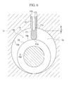
- Fig. 8 is a plan view showing a blade 17 and a blade groove 15 according to a fourth embodiment of the present invention.
- a hollow portion 171 formed in the blade 17 has the same shape as the hollow portion 171 formed in the blade 17 of the first embodiment, the hollow portion 171 of this embodiment may have the shape of the hollow portion 172 of the second embodiment, the shape of the hollow portion 173 of the third embodiment, etc.
- a maximum width W1 of the blade 17 at the rear end portion 17b is set slightly larger than an inner width W2 of the blade groove 15 such that both surfaces of the blade 17 are brought into contact with the inner surfaces of the blade groove 15 in a lightly elastically deformed state.
- the difference in width is set so as not to disturb smooth movement of the blade 17 in the blade groove 15 when inserted and operated into the blade groove 15.
- the gap at the sliding portion between the blade 17 and the blade groove 15 becomes very small, thus making compressed refrigerant less likely to leak from the gap. Accordingly, it is possible to reduce leakage of compressed refrigerant from the high-pressure side (the compression side 19) to the low-pressure side (the suction side 18), that is, gas leakage loss, thus enhancing the compression efficiency of the rotary compressor 1. Furthermore, unnecessary vibrations etc. of the blade 17 in the blade groove 15 can be effectively suppressed.
- the PV value (the product of the contact pressure P and the blade sliding speed V) acting on the side surfaces and the front end portion 17a of the blade 17 during the compression operation of the rotary compressor 1, to prevent wear, compressor seizure, etc. of the blade 17 to enhance the reliability, and to reduce leakage of compressed refrigerant from a gap of the sliding portion between the blade 17 and the blade groove 15, thus achieving enhanced compression efficiency.
- the present invention is not limited to the above-described embodiments, and modifications can be appropriately made without departing from the scope thereof.
- the present invention is not limited thereto and can be applied to a multicylinder rotary compressor that is provided with a plurality of cylinder chambers 10 or a multistage rotary compressor, as a matter of course.
- the present invention is applied to the hermetic-type rotary compressor 1 has been described, it is needless to say that the present invention can be applied to open-type compressors.
Landscapes
- Engineering & Computer Science (AREA)
- Mechanical Engineering (AREA)
- General Engineering & Computer Science (AREA)
- Applications Or Details Of Rotary Compressors (AREA)
Abstract
Description
- The present invention relates to a rotary compressor that is used to compress refrigerant gas etc.
- A rotary compressor has a rotor that rotates along an inner circumference of a cylinder chamber due to rotation of a rotating shaft and also includes a blade (vane) whose front end is brought into contact with an outer circumferential surface of the rotor to partition the inside of the cylinder chamber into a suction side and a compression side and that reciprocates in a radial direction in a blade groove provided in a cylinder main body, in accordance with rotation of the rotor. During compression operation, the blade reciprocates in the blade groove at a certain sliding speed while being subjected to a contact pressure caused by a pressure difference between the suction side and the compression side, the contact pressure occurs between the blade and side surfaces of the blade groove.
- Regarding the contact between the side surfaces of the blade and the side surfaces of the blade groove, which is provided in the cylinder main body, the entire side surfaces of the blade are not subjected to force of the contact pressure evenly over the entire side surfaces of the blade groove, and the blade is subjected to the above-described pressure difference and slides while being tilted by an amount depending on a gap of the sliding portion between the blade and the blade groove. Thus, as shown in
PTL 1, partial contact is caused. Specifically, the blade is subjected to force concentrated on a line due to partial contact, and the positions of said force move along the surface of the blade within the blade reciprocation range. - Although the sliding surfaces of the blade and the blade groove are lubricated by supplying lubricant oil that is mixed in fluid as refrigerant gas and the like, after long-term usage, oil film breakdown occurs due to the partial contact, thus causing wear to progress and causing rotor seizure, in some cases. Such events cause a reduction in reliability with respect to the life of a compressor, a reduction in compression performance due to an increase in gas leakage, etc. Thus,
PTL 1 discloses a technology in which concavo-convex-shaped fine grooves for holding oil are provided on both side surfaces of the blade closer to a front end and both side surfaces thereof closer to a rear end. Furthermore,PTL 2 discloses a technology in which fine concave portions (dimples) having appropriate opening area ratio, surface roughness, and depth are provided at portions where partial contact is likely to occur and portions where surface pressure is relatively high, in either the blade or the blade groove, or both. -
- {PTL 1} Japanese Unexamined Patent Application, Publication No.
S63-189683 - {PTL 2} Japanese Unexamined Patent Application, Publication No.
2011-21597 - As shown in
PTL PTLs - Therefore, if the area in which the fine grooves or the dimples are provided is increased more than its truly required area by focusing too much on the prevention of abnormal wear and compressor seizure, an increase in gas leakage could cause a reduction in compression efficiency. In particular, increasing the degree of eccentricity of a rotor can be considered as a means to increase displacement (capacity) of a compressor. However, in this case, the PV value of blade side surfaces (the product of the contact pressure P between the blade side surfaces and the blade-groove side surfaces and the blade sliding speed V (P×V)) is increased, so that the blade is likely to be seized. As a measure against this, it becomes more important to provide fine grooves or dimples for holding oil. However, increasing the area in which the fine grooves or the dimples are provided means an increase in the gas leakage gap, which leads to a reduction in efficiency caused by an increase in leakage loss.
- Furthermore, if the area in which the fine grooves or the dimples are provided is increased too much from the aspect of preventing abnormal wear and compressor seizure, as described in
PTL - The present invention is made in view of such circumstances, and an object thereof is to provide a rotary compressor that is capable of enhancing the reliability by preventing wear, compressor seizure, etc. of the blade and that is capable of achieving enhanced compression efficiency by reducing leakage of compressed fluid from a gap of a sliding portion between the blade and the blade groove.
- In order to make an improvement in the above-described circumstances, a rotary compressor of the present invention adopts the following solutions.
- Specifically, a first aspect of of the rotary compressor according to the present invention includes: a cylinder main body that forms a cylinder chamber; a rotor that is fitted onto an eccentric part of a rotating shaft, that orbits in the cylinder chamber in accordance with rotation of the rotating shaft, and whose outer circumferential surface is brought into sliding contact with an inner circumferential surface of the cylinder chamber; and a blade in which a front end portion is brought into contact with the outer circumferential surface of the rotor to partition the inside of the cylinder chamber into a suction side and a compression side, the blade being configured to slide in a groove provided in the cylinder main body so as to be extended from and retracted into the groove in accordance with orbiting of the rotor, wherein the blade has a hollow portion therein that allows the blade to be bent in a thickness direction thereof; and the hollow portion is open to the outside of the blade at a rear end portion and both side portions of the blade.
- In the above-described configuration, the blade inserted into the blade groove of the cylinder main body comes out from the blade groove in accordance with orbiting of the rotor, and the front end portion of the blade is brought into contact with the outer circumferential surface of the rotor to partition the space in the cylinder chamber into the suction side and the compression side, thus performing the compression operation.
- At this time, because the blade is subjected to a contact pressure due to the pressure difference between the suction side and the compression side, the blade slides while being tilted toward the suction side by an amount in accordance with a gap of the sliding portion between the blade and the blade groove. At the same time, the blade is bent slightly toward the suction side due to the hollow portion formed in the blade.
- When the blade is bent toward the suction side in this way, contact areas at portions where the side surfaces of the blade are brought into partial contact with the blade groove are increased, which means that those portions are brought into surface contact with the blade groove, thus reducing a PV value. Therefore, an oil film is less likely to breakdown at contact portions between the blade and the blade groove, thus preventing wear from progressing and compressor seizure from occurring at the contact portions, and enhancing the reliability of the rotary compressor.
- Furthermore, when compressed fluid flows from a gap of a sliding portion between the blade and the blade groove into the hollow portion in the blade, the pressure of the fluid brings both surfaces of the blade into contact with inner surfaces of the blade groove through elastic deformation. Accordingly, the gap becomes small, thus improving the sealability, and leakage of the compressed fluid from a high-pressure side (the compression side) to a low-pressure side (the suction side) can be reduced (gas leakage loss can be reduced), thus enhancing the compression efficiency of the rotary compressor.
- In the above-described configuration, it is desirable that the hollow portion be formed from the rear end to a vicinity of a front end portion of the blade.
- By forming the hollow portion from the rear end to the front end portion of the blade in this way, the thickness of the front end portion of the blade is reduced, and the blade front end portion is softened and is brought into contact with the outer circumferential surface of the rotor in a wide area. Accordingly, it is possible to reduce the contact surface pressure at the front end portion of the blade, which prevents breakdown of an oil film, wear, and compressor seizure, thus enhancing the reliability of the rotary compressor.
- In the above-described configuration, it is preferable that the hollow portion is formed from the rear end and at least to a position which is located at a front end side relative to a rear end position of the blade at which the blade protrudes from the blade groove into the cylinder chamber when the blade is fully extended.
- By forming the hollow portion from the rear end to the above-described position, it is possible to reduce the machining cost, compared with the case in which the hollow portion is formed from the rear end to the vicinity of the front end portion of the blade.
- Furthermore, a portion of the blade closer to the rear end portion is hollowed, a portion of the blade closer to the front end portion is made solid, and the length of the hollow portion is adjustable, thereby making it possible to adjust the amount of bending of the blade in accordance with the characteristics of the rotary compressor.
- In the above-described configuration, the hollow portion may be provided with a through-hole that penetrates the blade in a vicinity of a front end portion along the axial direction of the rotating shaft and a slit that is formed so as to extend from the rear end portion of the blade to the through-hole and that has an inner width narrower than an inner diameter of the through-hole.
- With the above-described configuration, it is possible to make the thickness in the vicinity of the front end portion of the blade thinner than the thicknesses of intermediate and other portions of the blade and to soften the front end portion of the blade to bring it into contact with the outer circumferential surface of the rotor in a wide area, thus reducing surface pressure, which prevents breakdown of an oil film, wear, and compressor seizure of the blade, and enhancing the reliability of the rotary compressor.
- In the above-described configuration, a maximum width of the blade at the rear end portion may be set larger than an inner width of the blade groove such that both surfaces of the blade are brought into contact with inner surfaces of the blade groove in a lightly elastically deformed state.
- By doing so, a gap of the sliding portion between the blade and the blade groove becomes very small, thus making compressed fluid less likely to leak from the gap. Accordingly, it is possible to reduce leakage of compressed fluid from a high-pressure side to a low-pressure side (gas leakage loss), and to enhance the compression efficiency of the rotary compressor.
- As described above, according to the rotary compressor of the present invention, it is possible to reduce the PV value (the product of the contact pressure P and the blade sliding speed V) acting on the side surfaces and the front end portion of the blade during the compression operation, which prevents wear, compressor seizure, etc. of the blade and enhances the reliability, and to reduce leakage of compressed fluid from a gap of the sliding portion between the blade and the blade groove, thus achieving enhanced compression efficiency.
-
- {
Fig. 1} Fig. 1 is a longitudinal sectional view showing an example rotary compressor to which the present invention can be applied. - {
Fig. 2} Fig. 2 is a transverse sectional view showing a compression mechanism portion of the rotary compressor, along the line II-II ofFig. 1 . - {
Fig. 3} Fig. 3 is a view schematically showing the behavior of a blade during compression operation of the rotary compressor. - {
Fig. 4} Fig. 4 is a plan view showing the vicinity of a blade according to a first embodiment of the present invention. - {
Fig. 5} Fig. 5 is a plan view showing a function of the blade shown inFig. 4 . - {
Fig. 6} Fig. 6 is a plan view showing the vicinity of a blade according to a second embodiment of the present invention. - {
Fig. 7} Fig. 7 is a plan view showing the vicinity of a blade according to a third embodiment of the present invention. - {
Fig. 8} Fig. 8 is a plan view showing a blade and a blade groove according to a fourth embodiment of the present invention. - Embodiments of the present invention will be described below with reference to
Figs. 1 to 8 . -
Fig. 1 is a longitudinal sectional view showing an example rotary compressor to which the present invention can be applied.Fig. 2 is a transverse sectional view showing a compression mechanism portion of the rotary compressor, along the line II-II ofFig. 1 . - As shown in
Fig. 1 , arotary compressor 1 includes a cylindricalhermetic housing 2, anelectric motor 3 that is installed at a center portion in thehermetic housing 2, and acompression mechanism portion 4 that is provided below theelectric motor 3 and is driven by theelectric motor 3 to compress refrigerant gas. - The
hermetic housing 2 is a cylindrical hollow housing in which atop cover 2c and abottom cover 2b are welded at upper and lower ends of acylindrical part 2a. One end of asuction pipe 5 connected to thecompression mechanism portion 4 is connected to a lower portion of thecylindrical part 2a so as to penetrate therethrough, andinstallation legs 6 of the compressor are provided at places on an outer circumferential portion of thecylindrical part 2a. Thesuction pipe 5 is connected to anaccumulator 7 that is supported on the outer circumference of thehermetic housing 2, and theaccumulator 7 is connected to a refrigeration cycle. Furthermore, adischarge pipe 8 that is connected to the refrigeration cycle (not shown) is connected to thetop cover 2c so as to penetrate therethrough. - The
electric motor 3 is composed of astator 3a and arotor 3b. Thestator 3a is fixed to an inner circumferential surface of thecylindrical part 2a of thehermetic housing 2, and therotor 3b is rotatably fitted into an inner circumference of thestator 3a so as to have a predetermined clearance, with therotor 3b being fixed to a rotating shaft (crankshaft) 9. A lower end portion of therotating shaft 9 extends toward thecompression mechanism portion 4, which is located below, and is rotatably supported via anupper bearing 12 and alower bearing 13, to be described later, that constitute thecompression mechanism portion 4. Furthermore, therotating shaft 9 is provided with aneccentric part 9a at a lower portion thereof and anoil supply hole 9b therein along the axial direction. - The
compression mechanism portion 4 is composed of a cylindermain body 11, theupper bearing 12, thelower bearing 13, arotor 14, and ablade 17. - The cylinder
main body 11 has acolumnar cylinder chamber 10 on the inner circumferential side and is fixed to the inner circumferential surface of thehermetic housing 2 at multiple points on the circumference ofhousing 2 through welding. - The
upper bearing 12 and thelower bearing 13 are screwed to upper and lower surfaces of the cylindermain body 11, respectively, thus sealing upper and lower surfaces of thecylinder chamber 10 and also rotatably supporting therotating shaft 9. - The
rotor 14 is a cylindrical part, and is hermetically and rotatably fitted onto the outer circumference of theeccentric part 9a of therotating shaft 9, and orbits in thecylinder chamber 10 in accordance with eccentric rotation of theeccentric part 9a, and an outercircumferential surface 14a (seeFig. 2 ) thereof is brought into sliding contact with or rolls on an innercircumferential surface 10a of thecylinder chamber 10. - The
blade 17 is a plate-like part, which is also generally called a vane, and is slidably provided in oneblade groove 15 that is formed in the cylindermain body 11 and that extends in the radial direction. Arear end portion 17b of theblade 17 is pressed by ablade spring 16 that is provided in theblade groove 15 in a manner allowing elastic deformation, so that theblade 17 is always biased in the direction in which theblade 17 protrudes toward thecylinder chamber 10. - Because a
front end portion 17a of theblade 17 abuts on the outercircumferential surface 14a of the rotor 14 (contact resulting from biasing by the spring), the space in thecylinder chamber 10 is partitioned by theblade 17 into asuction side 18 and acompression side 19. Theblade 17 reciprocates in theblade groove 15 in accordance with orbiting of therotor 14, thus being extended from and retracted into the groove. - A
suction port 20 opens at thesuction side 18 of thecylinder chamber 10, and low-pressure refrigerant gas is suctioned to thesuction side 18 via thesuction pipe 5 connected to thesuction port 20. Furthermore, adischarge port 21 opens at thecompression side 19 of thecylinder chamber 10, and compressed gas is discharged, via thedischarge port 21 and adischarge valve 22 for opening and closing thedischarge port 21, to adischarge chamber 24 that is formed by adischarge cover 23 provided on theupper bearing 12. - An
oil pump 25 that pumps lubricant oil filled in a bottom portion of thehermetic housing 2 into theoil supply hole 9b, which is located inside the shaft, is provided near the lower end portion of therotating shaft 9, so that the lubricant oil can be supplied to a lubrication point of thecompression mechanism portion 4 via theoil pump 25 and theoil supply hole 9b. The above-described configuration of therotary compressor 1 is not special, and is known. - As shown in
Fig. 2 , as is well-known, in the compression operation of therotary compressor 1, during a first orbiting of therotor 14 in which it orbits in the direction of the arrow from a top dead center across thesuction port 20, due to rotation of the rotating shaft 9 (theeccentric part 9a), while the volume of thesuction side 18 is being gradually enlarged, low-pressure refrigerant gas is suctioned into thesuction side 18 via thesuction port 20. This low-pressure gas is compressed while the volume of thesuction side 18 is being gradually reduced after the suction process is stopped due to the rotation of the rotor, pushes and opens thedischarge valve 22 from thecompression side 19 when the gas is compressed to a predetermined pressure, and is discharged to thedischarge chamber 24 via thedischarge port 21. - The
blade 17 is pushed by theblade spring 16 during the aforementioed operation, with thefront end portion 17a thereof being brought into contact with the outer circumferential surface of therotor 14, theblade 17 slides to be extended from and retracted into theblade groove 15, in accordance with orbiting of therotor 14.Fig. 3 schematically shows the behavior of theblade 17 when it protrudes into thecylinder chamber 10 during the compression operation. Theblade 17 is extended and retracted (reciprocates) with thefront end portion 17a thereof protruding toward thecylinder chamber 10, except for the position at the top dead center. Thus, theblade 17 is subjected to a pressure difference in the direction of the arrow toward thesuction side 18 due to the pressure difference Δp between the pressure at thesuction side 18 and the pressure at thecompression side 19. - For this reason, the
blade 17 slides while being tilted relative to theblade groove 15 by an amount in accordance with a slide gap, so that theblade 17 slides while being brought into partial contact with theblade groove 15 at aposition 17c that is in contact with a front end of a side surface of theblade groove 15 on thesuction side 18 and at aposition 17d that is in contact with the vicinity of a rear end of a side surface of theblade groove 15 on thecompression side 19. - Specifically, the
blade 17 is subjected to force concentrated on a line due to the partial contact, and the positions on theblade 17 that are subjected to the load change due to the reciprocation of theblade 17. Because of this partial contact, there is a risk that an oil film of lubricant oil mixed in refrigerant gas may breakdown, thus causing wear to progress and causing compressor seizure. Thus, in the present invention, a hollow portion is provided in theblade 17, as described below. -
Fig. 4 is a plan view showing the vicinity of ablade 17 according to a first embodiment of the present invention. - The
blade 17 has ahollow portion 171 therein. Thehollow portion 171 is open on three sides, i.e., therear end portion 17b of theblade 17 and both side portions thereof, namely, an upper side and a lower side of theblade 17. Furthermore, thehollow portion 171 is formed from the rear end to the vicinity of thefront end portion 17a of theblade 17. More specifically, respective portions of theblade 17 that surround thehollow portion 171 have a fixed thickness. - Here, the width of the
hollow portion 171 or the thicknesses of the respective portions of theblade 17 are set to such a thickness that theblade 17 can be slightly bent in a thickness direction thereof when the above-described pressure difference Δp between the pressure at thesuction side 18 and the pressure at thecompression side 19 is applied on theblade 17 during the compression operation of therotary compressor 1, as shown inFig. 5 . - The
hollow portion 171 can be formed simultaneously when theblade 17 is formed by bending a sheet-metal material into a channel section shape in a plan view. Alternatively, after theblade 17 is cut out from a solid metal material or is punched by press work, thehollow portion 171 may be formed by machining. - During the compression operation of the
rotary compressor 1, theblade 17, which has thehollow portion 171 provided therein, is subjected to a contact pressure due to the pressure difference Δp between thesuction side 18 and thecompression side 19 and slides while being tilted toward thesuction side 18 by an amount in accordance with a slide gap between theblade 17 and theblade groove 15, as shown inFig. 5 . At the same time, theblade 17 is slightly bent toward thesuction side 18. - When the
blade 17 is bent toward thesuction side 18 in this way, the contact areas at thepositions blade 17 are brought into partial contact with theblade groove 15 are increased, thus bringing thepositions blade groove 15 and reducing a PV value. Therefore, the oil film is less likely to breakdown at contact portions between theblade 17 and theblade groove 15, thus preventing wear from progressing and compressor seizure from occurring at the contact portions and enhancing the reliability of therotary compressor 1. - Furthermore, when compressed refrigerant gas flows from the gap of the sliding portion between the
blade 17 and theblade groove 15 into thehollow portion 171 in theblade 17, the pressure of the compressed refrigerant brings both of the surfaces of theblade 17 into contact with the inner surfaces of theblade groove 15 through elastic deformation. Accordingly, the slide gap becomes small, thus improving the sealability, and leakage of the compressed refrigerant from a high-pressure side (the compression side 19) to a low-pressure side (the suction side 18) (gas leakage loss) can be reduced, thus enhancing the compression efficiency of therotary compressor 1. - Furthermore, because the
hollow portion 171 is formed from the rear end to the vicinity of thefront end portion 17a of theblade 17, the thickness of the bladefront end portion 17a is reduced, and the bladefront end portion 17a is softened and brought into contact with the outercircumferential surface 14a of therotor 14 in a wide area. Accordingly, it is possible to reduce the contact surface pressure at the bladefront end portion 17a, which prevents breakdown of the oil film, wear, and compressor seizure, thus enhancing the reliability of therotary compressor 1. -
Fig. 6 is a plan view showing the vicinity of ablade 17 according to a second embodiment of the present invention. - In the
blade 17 shown here, ahollow portion 172 formed therein is shorter than thehollow portion 171 of the first embodiment. - Specifically, when the
blade 17 is fully extended, as shown inFig. 6 , thehollow portion 172 only needs to be formed from the rear end to at least a position that is located at the front end side relative to arear end position 17e at which theblade 17 protrudes from theblade groove 15 into thecylinder chamber 10. In this embodiment, thehollow portion 172 is formed to have a length L from therear end position 17e. - By forming the
hollow portion 172 from the rear end to the above-described position, it is possible to reduce the machining cost, compared with the case in which thehollow portion 171 is formed from the rear end to the vicinity of thefront end portion 17a of theblade 17, as shown inFig. 4 . The advantageous effect produced when theblade 17 is bent due to thehollow portion 172 is the same as or similar to that in the first embodiment. - Furthermore, in this way, a portion of the
blade 17 closer to therear end portion 17b is hollowed, a portion of theblade 17 closer to thefront end portion 17a is made solid, and the length of the hollow portion 172 (the length L) is adjusted, thereby making it possible to appropriately adjust the amount of bending of theblade 17 in accordance with the characteristics of therotary compressor 1. -
Fig. 7 is a plan view showing the vicinity of ablade 17 according to a third embodiment of the present invention. - In this embodiment, a
hollow portion 173 formed in theblade 17 has a through-hole 173a that penetrates theblade 17 in the vicinity of thefront end portion 17a along the axial direction of the rotating shaft 9 (theeccentric part 9a) and aslit 173b that is formed so as to extend from therear end portion 17b of theblade 17 to the through-hole 173a. - The through-
hole 173a is formed by drilling using a drill, for example, and theslit 173b is formed by cutting through wire cutting, for example. Here, an inner width W of theslit 173b is less than an inner diameter d of the through-hole 173a. - With the above-described configuration, it is possible to make the thickness in the vicinity of the
front end portion 17a of theblade 17 thinner than the thicknesses of intermediate and other portions of theblade 17 and to soften the bladefront end portion 17a to bring it into contact with the outercircumferential surface 14a of therotor 14 in a wide area, thus reducing surface pressure, which prevents breakdown of the oil film, wear, and compressor seizure of theblade 17, and enhancing the reliability of therotary compressor 1. -
Fig. 8 is a plan view showing ablade 17 and ablade groove 15 according to a fourth embodiment of the present invention. - In this embodiment, although a
hollow portion 171 formed in theblade 17 has the same shape as thehollow portion 171 formed in theblade 17 of the first embodiment, thehollow portion 171 of this embodiment may have the shape of thehollow portion 172 of the second embodiment, the shape of thehollow portion 173 of the third embodiment, etc. - In this embodiment, a maximum width W1 of the
blade 17 at therear end portion 17b is set slightly larger than an inner width W2 of theblade groove 15 such that both surfaces of theblade 17 are brought into contact with the inner surfaces of theblade groove 15 in a lightly elastically deformed state. The difference in width is set so as not to disturb smooth movement of theblade 17 in theblade groove 15 when inserted and operated into theblade groove 15. - By doing so, the gap at the sliding portion between the
blade 17 and theblade groove 15 becomes very small, thus making compressed refrigerant less likely to leak from the gap. Accordingly, it is possible to reduce leakage of compressed refrigerant from the high-pressure side (the compression side 19) to the low-pressure side (the suction side 18), that is, gas leakage loss, thus enhancing the compression efficiency of therotary compressor 1. Furthermore, unnecessary vibrations etc. of theblade 17 in theblade groove 15 can be effectively suppressed. - Therefore, according to the first to fourth embodiments, it is possible to reduce the PV value (the product of the contact pressure P and the blade sliding speed V) acting on the side surfaces and the
front end portion 17a of theblade 17 during the compression operation of therotary compressor 1, to prevent wear, compressor seizure, etc. of theblade 17 to enhance the reliability, and to reduce leakage of compressed refrigerant from a gap of the sliding portion between theblade 17 and theblade groove 15, thus achieving enhanced compression efficiency. - Note that the present invention is not limited to the above-described embodiments, and modifications can be appropriately made without departing from the scope thereof. For example, in the above-described embodiments, although a description has been given as an example case in which the present invention is applied to the single-
cylinder rotary compressor 1, which is provided with onecylinder chamber 10, the present invention is not limited thereto and can be applied to a multicylinder rotary compressor that is provided with a plurality ofcylinder chambers 10 or a multistage rotary compressor, as a matter of course. Furthermore, although an example case in which the present invention is applied to the hermetic-type rotary compressor 1 has been described, it is needless to say that the present invention can be applied to open-type compressors. -
- 1
- rotary compressor
- 3
- electric motor
- 4
- compression mechanism portion
- 9
- rotating shaft
- 9a
- eccentric part
- 10
- cylinder chamber
- 10a
- inner circumferential surface of cylinder chamber
- 11
- cylinder main body
- 14
- rotor
- 14a
- outer circumferential surface of rotor
- 15
- blade groove
- 17
- blade
- 17a
- front end portion of blade
- 17b
- rear end portion of blade
- 17e
- position at which blade protrudes from blade groove when
- fully
- extended
- 18
- suction side
- 19
- compression side
- 171, 172, 173
- hollow portions
- 173a
- through-hole
- 173b
- slit
Claims (5)
- A rotary compressor (1) characterized in that it comprises:a cylinder main body (11) that forms a cylinder chamber (10) ;a rotor (14) that is fitted onto an eccentric part (9a) of a rotating shaft (9), that orbits in the cylinder chamber (10) in accordance with rotation of the rotating shaft (9), and whose outer circumferential surface (14a) is brought into sliding contact with an inner circumferential surface (10a) of the cylinder chamber (10); anda blade (17) in which a front end portion (17a) is brought into contact with the outer circumferential surface of the rotor (14) to partition the inside of the cylinder chamber (10) into a suction side (18) and a compression side (19), the blade being configured to slide in a groove (15) provided in the cylinder main body (11) so as to be extended from and retracted into the groove (15) in accordance with orbiting of the rotor (14),wherein the blade (17) has a hollow portion (171; 172; 173) therein that allows the blade (17) to be bent in a thickness direction thereof; andthe hollow portion (171; 172; 173) is open to the outside of the blade at a rear end portion and both side portions of the blade.
- The rotary compressor (1) according to claim 1, wherein the hollow portion (171; 173) is formed from the rear end (17b) to a vicinity of a front end portion (17a) of the blade (17).
- The rotary compressor (1) according to claim 1, wherein the hollow portion (172) is formed from the rear end (17b) and at least to a position which is located at a front end side relative to a rear end position (17c) of the blade (17) at which the blade protrudes from the blade groove (15) into the cylinder chamber (10) when the blade is fully extended.
- The rotary compressor according to claim 1 or 2, wherein the hollow portion (173) is provided with a through-hole (173a) that penetrates the blade in a vicinity of a front end portion (17a) along the axial direction of the rotating shaft, and a slit (173b) that is formed so as to extend from the rear end portion (17b) of the blade to the through-hole (173a) and that has an inner width (W) narrower than an inner diameter (d) of the through-hole (173a).
- The rotary compressor according to one of claims 1 to 4, wherein a maximum width (W1) of the blade at the rear end portion (17b) is set larger than an inner width (W2) of the blade groove (15) such that both surfaces of the blade are brought into contact with inner surfaces of the blade groove (15) in a lightly elastically deformed state.
Applications Claiming Priority (1)
| Application Number | Priority Date | Filing Date | Title |
|---|---|---|---|
| JP2014061772A JP6396050B2 (en) | 2014-03-25 | 2014-03-25 | Rotary compressor |
Publications (3)
| Publication Number | Publication Date |
|---|---|
| EP2924292A2 true EP2924292A2 (en) | 2015-09-30 |
| EP2924292A3 EP2924292A3 (en) | 2015-10-21 |
| EP2924292B1 EP2924292B1 (en) | 2016-09-07 |
Family
ID=52807568
Family Applications (1)
| Application Number | Title | Priority Date | Filing Date |
|---|---|---|---|
| EP15159760.6A Active EP2924292B1 (en) | 2014-03-25 | 2015-03-19 | Rotary compressor |
Country Status (2)
| Country | Link |
|---|---|
| EP (1) | EP2924292B1 (en) |
| JP (1) | JP6396050B2 (en) |
Cited By (4)
| Publication number | Priority date | Publication date | Assignee | Title |
|---|---|---|---|---|
| CN105545738A (en) * | 2016-02-25 | 2016-05-04 | 珠海凌达压缩机有限公司 | Sliding vane and compressor with same |
| CN108757456A (en) * | 2018-06-01 | 2018-11-06 | 广东美芝精密制造有限公司 | Rotary compressor, gas compression system, refrigeration system and heat pump system |
| CN115539356A (en) * | 2022-10-21 | 2022-12-30 | 广东美芝精密制造有限公司 | Vanes, Pump Body Components and Compressors |
| CN121017683A (en) * | 2025-10-30 | 2025-11-28 | 宁波甬微集团有限公司 | Manufacturing method of compressor sliding vane |
Families Citing this family (6)
| Publication number | Priority date | Publication date | Assignee | Title |
|---|---|---|---|---|
| JP2018100626A (en) | 2016-12-20 | 2018-06-28 | 三菱重工サーマルシステムズ株式会社 | Hermetic electric compressor and refrigeration cycle including the same |
| CN108757458B (en) * | 2018-06-01 | 2020-04-03 | 广东美芝精密制造有限公司 | Rotary compressor, gas compression system, refrigeration system and heat pump system |
| CN108757457B (en) * | 2018-06-01 | 2020-04-17 | 广东美芝精密制造有限公司 | Rotary compressor, gas compression system, refrigeration system and heat pump system |
| WO2019227842A1 (en) * | 2018-06-01 | 2019-12-05 | 广东美芝精密制造有限公司 | Rotary compressor, gas compression system, refrigeration system and heat pump system |
| CN108825498B (en) * | 2018-06-01 | 2021-04-06 | 广东美芝精密制造有限公司 | Rotary compressor, gas compression system, refrigeration system and heat pump system |
| CN110374874B (en) * | 2019-07-29 | 2024-11-01 | 黄石东贝压缩机有限公司 | Multiple anti-leakage spring sheet type sliding block mechanism |
Citations (2)
| Publication number | Priority date | Publication date | Assignee | Title |
|---|---|---|---|---|
| JPS63189683A (en) | 1987-02-03 | 1988-08-05 | Matsushita Electric Ind Co Ltd | Partition vane of hermetic compressor |
| JP2011021597A (en) | 2009-06-16 | 2011-02-03 | Panasonic Corp | Sliding member, apparatus equipped therewith, and surface treating method for sliding member |
Family Cites Families (8)
| Publication number | Priority date | Publication date | Assignee | Title |
|---|---|---|---|---|
| GB424555A (en) * | 1934-03-23 | 1935-02-22 | Karl Steinmann | Rotary piston compressor |
| JPS491046Y1 (en) * | 1968-05-30 | 1974-01-11 | ||
| FR2034144A1 (en) * | 1969-02-11 | 1970-12-11 | Bonneau Roland | |
| JPS56157394U (en) * | 1980-04-25 | 1981-11-24 | ||
| JPH07189924A (en) * | 1993-12-28 | 1995-07-28 | Hitachi Ltd | Rotary compressor |
| JP2001050183A (en) * | 1999-08-06 | 2001-02-23 | Matsushita Electric Ind Co Ltd | Rotary compressor |
| JP4401365B2 (en) * | 2006-03-31 | 2010-01-20 | 三洋電機株式会社 | Rotary compressor |
| JP2012197725A (en) * | 2011-03-22 | 2012-10-18 | Nippon Soken Inc | Rolling piston compressor, and vane |
-
2014
- 2014-03-25 JP JP2014061772A patent/JP6396050B2/en active Active
-
2015
- 2015-03-19 EP EP15159760.6A patent/EP2924292B1/en active Active
Patent Citations (2)
| Publication number | Priority date | Publication date | Assignee | Title |
|---|---|---|---|---|
| JPS63189683A (en) | 1987-02-03 | 1988-08-05 | Matsushita Electric Ind Co Ltd | Partition vane of hermetic compressor |
| JP2011021597A (en) | 2009-06-16 | 2011-02-03 | Panasonic Corp | Sliding member, apparatus equipped therewith, and surface treating method for sliding member |
Cited By (4)
| Publication number | Priority date | Publication date | Assignee | Title |
|---|---|---|---|---|
| CN105545738A (en) * | 2016-02-25 | 2016-05-04 | 珠海凌达压缩机有限公司 | Sliding vane and compressor with same |
| CN108757456A (en) * | 2018-06-01 | 2018-11-06 | 广东美芝精密制造有限公司 | Rotary compressor, gas compression system, refrigeration system and heat pump system |
| CN115539356A (en) * | 2022-10-21 | 2022-12-30 | 广东美芝精密制造有限公司 | Vanes, Pump Body Components and Compressors |
| CN121017683A (en) * | 2025-10-30 | 2025-11-28 | 宁波甬微集团有限公司 | Manufacturing method of compressor sliding vane |
Also Published As
| Publication number | Publication date |
|---|---|
| JP6396050B2 (en) | 2018-09-26 |
| JP2015183613A (en) | 2015-10-22 |
| EP2924292A3 (en) | 2015-10-21 |
| EP2924292B1 (en) | 2016-09-07 |
Similar Documents
| Publication | Publication Date | Title |
|---|---|---|
| EP2924292B1 (en) | Rotary compressor | |
| US9903370B2 (en) | Scroll compressor with reduced upsetting moment | |
| AU2016225716B2 (en) | Scroll-type compressor | |
| US9382907B2 (en) | Vane-type compressor having an oil supply channel between the oil resevoir and vane angle adjuster | |
| US20130171018A1 (en) | Screw compressor | |
| JP5691352B2 (en) | Scroll compressor | |
| JP5657144B2 (en) | Vane type compressor | |
| AU2005261267B2 (en) | Rotary fluid machine | |
| JP2014125908A (en) | Scroll compressor | |
| US11454239B2 (en) | Rotary compressor | |
| US12228128B2 (en) | Compressor and moving scroll thereof | |
| JP6032958B2 (en) | Rotary compressor | |
| JPWO2002063171A1 (en) | Scroll compressor | |
| JP2009062929A (en) | Rotary compressor and refrigeration cycle apparatus | |
| JPWO2004029461A1 (en) | Scroll compressor | |
| JP6403603B2 (en) | Rotary compressor and refrigeration cycle apparatus | |
| US20050207926A1 (en) | Scroll compressor | |
| JP4784296B2 (en) | Rotary fluid machine | |
| JP2018109388A (en) | Rotary compressor | |
| JP2015105616A (en) | Rotary compressor | |
| JP2017053263A (en) | Rotary compressor | |
| JP4733558B2 (en) | Fluid machinery and refrigeration cycle equipment | |
| JPWO2018138840A1 (en) | Rotary compressor | |
| JP4609520B2 (en) | Rotary fluid machine | |
| JP2017015064A (en) | Compressor |
Legal Events
| Date | Code | Title | Description |
|---|---|---|---|
| PUAL | Search report despatched |
Free format text: ORIGINAL CODE: 0009013 |
|
| PUAI | Public reference made under article 153(3) epc to a published international application that has entered the european phase |
Free format text: ORIGINAL CODE: 0009012 |
|
| AK | Designated contracting states |
Kind code of ref document: A2 Designated state(s): AL AT BE BG CH CY CZ DE DK EE ES FI FR GB GR HR HU IE IS IT LI LT LU LV MC MK MT NL NO PL PT RO RS SE SI SK SM TR |
|
| AX | Request for extension of the european patent |
Extension state: BA ME |
|
| AK | Designated contracting states |
Kind code of ref document: A3 Designated state(s): AL AT BE BG CH CY CZ DE DK EE ES FI FR GB GR HR HU IE IS IT LI LT LU LV MC MK MT NL NO PL PT RO RS SE SI SK SM TR |
|
| AX | Request for extension of the european patent |
Extension state: BA ME |
|
| RIC1 | Information provided on ipc code assigned before grant |
Ipc: F04C 18/356 20060101AFI20150914BHEP Ipc: F01C 1/356 20060101ALI20150914BHEP |
|
| 17P | Request for examination filed |
Effective date: 20151207 |
|
| RBV | Designated contracting states (corrected) |
Designated state(s): AL AT BE BG CH CY CZ DE DK EE ES FI FR GB GR HR HU IE IS IT LI LT LU LV MC MK MT NL NO PL PT RO RS SE SI SK SM TR |
|
| GRAP | Despatch of communication of intention to grant a patent |
Free format text: ORIGINAL CODE: EPIDOSNIGR1 |
|
| INTG | Intention to grant announced |
Effective date: 20160411 |
|
| GRAS | Grant fee paid |
Free format text: ORIGINAL CODE: EPIDOSNIGR3 |
|
| GRAA | (expected) grant |
Free format text: ORIGINAL CODE: 0009210 |
|
| AK | Designated contracting states |
Kind code of ref document: B1 Designated state(s): AL AT BE BG CH CY CZ DE DK EE ES FI FR GB GR HR HU IE IS IT LI LT LU LV MC MK MT NL NO PL PT RO RS SE SI SK SM TR |
|
| REG | Reference to a national code |
Ref country code: GB Ref legal event code: FG4D |
|
| REG | Reference to a national code |
Ref country code: CH Ref legal event code: EP |
|
| REG | Reference to a national code |
Ref country code: IE Ref legal event code: FG4D |
|
| REG | Reference to a national code |
Ref country code: AT Ref legal event code: REF Ref document number: 827147 Country of ref document: AT Kind code of ref document: T Effective date: 20161015 |
|
| REG | Reference to a national code |
Ref country code: DE Ref legal event code: R096 Ref document number: 602015000277 Country of ref document: DE |
|
| REG | Reference to a national code |
Ref country code: LT Ref legal event code: MG4D |
|
| REG | Reference to a national code |
Ref country code: NL Ref legal event code: MP Effective date: 20160907 |
|
| PG25 | Lapsed in a contracting state [announced via postgrant information from national office to epo] |
Ref country code: LT Free format text: LAPSE BECAUSE OF FAILURE TO SUBMIT A TRANSLATION OF THE DESCRIPTION OR TO PAY THE FEE WITHIN THE PRESCRIBED TIME-LIMIT Effective date: 20160907 Ref country code: HR Free format text: LAPSE BECAUSE OF FAILURE TO SUBMIT A TRANSLATION OF THE DESCRIPTION OR TO PAY THE FEE WITHIN THE PRESCRIBED TIME-LIMIT Effective date: 20160907 Ref country code: NO Free format text: LAPSE BECAUSE OF FAILURE TO SUBMIT A TRANSLATION OF THE DESCRIPTION OR TO PAY THE FEE WITHIN THE PRESCRIBED TIME-LIMIT Effective date: 20161207 Ref country code: RS Free format text: LAPSE BECAUSE OF FAILURE TO SUBMIT A TRANSLATION OF THE DESCRIPTION OR TO PAY THE FEE WITHIN THE PRESCRIBED TIME-LIMIT Effective date: 20160907 Ref country code: FI Free format text: LAPSE BECAUSE OF FAILURE TO SUBMIT A TRANSLATION OF THE DESCRIPTION OR TO PAY THE FEE WITHIN THE PRESCRIBED TIME-LIMIT Effective date: 20160907 |
|
| REG | Reference to a national code |
Ref country code: AT Ref legal event code: MK05 Ref document number: 827147 Country of ref document: AT Kind code of ref document: T Effective date: 20160907 |
|
| PG25 | Lapsed in a contracting state [announced via postgrant information from national office to epo] |
Ref country code: SE Free format text: LAPSE BECAUSE OF FAILURE TO SUBMIT A TRANSLATION OF THE DESCRIPTION OR TO PAY THE FEE WITHIN THE PRESCRIBED TIME-LIMIT Effective date: 20160907 Ref country code: ES Free format text: LAPSE BECAUSE OF FAILURE TO SUBMIT A TRANSLATION OF THE DESCRIPTION OR TO PAY THE FEE WITHIN THE PRESCRIBED TIME-LIMIT Effective date: 20160907 Ref country code: LV Free format text: LAPSE BECAUSE OF FAILURE TO SUBMIT A TRANSLATION OF THE DESCRIPTION OR TO PAY THE FEE WITHIN THE PRESCRIBED TIME-LIMIT Effective date: 20160907 Ref country code: NL Free format text: LAPSE BECAUSE OF FAILURE TO SUBMIT A TRANSLATION OF THE DESCRIPTION OR TO PAY THE FEE WITHIN THE PRESCRIBED TIME-LIMIT Effective date: 20160907 Ref country code: GR Free format text: LAPSE BECAUSE OF FAILURE TO SUBMIT A TRANSLATION OF THE DESCRIPTION OR TO PAY THE FEE WITHIN THE PRESCRIBED TIME-LIMIT Effective date: 20161208 |
|
| REG | Reference to a national code |
Ref country code: FR Ref legal event code: PLFP Year of fee payment: 3 |
|
| PG25 | Lapsed in a contracting state [announced via postgrant information from national office to epo] |
Ref country code: RO Free format text: LAPSE BECAUSE OF FAILURE TO SUBMIT A TRANSLATION OF THE DESCRIPTION OR TO PAY THE FEE WITHIN THE PRESCRIBED TIME-LIMIT Effective date: 20160907 Ref country code: EE Free format text: LAPSE BECAUSE OF FAILURE TO SUBMIT A TRANSLATION OF THE DESCRIPTION OR TO PAY THE FEE WITHIN THE PRESCRIBED TIME-LIMIT Effective date: 20160907 |
|
| PG25 | Lapsed in a contracting state [announced via postgrant information from national office to epo] |
Ref country code: AT Free format text: LAPSE BECAUSE OF FAILURE TO SUBMIT A TRANSLATION OF THE DESCRIPTION OR TO PAY THE FEE WITHIN THE PRESCRIBED TIME-LIMIT Effective date: 20160907 Ref country code: SM Free format text: LAPSE BECAUSE OF FAILURE TO SUBMIT A TRANSLATION OF THE DESCRIPTION OR TO PAY THE FEE WITHIN THE PRESCRIBED TIME-LIMIT Effective date: 20160907 Ref country code: PL Free format text: LAPSE BECAUSE OF FAILURE TO SUBMIT A TRANSLATION OF THE DESCRIPTION OR TO PAY THE FEE WITHIN THE PRESCRIBED TIME-LIMIT Effective date: 20160907 Ref country code: IS Free format text: LAPSE BECAUSE OF FAILURE TO SUBMIT A TRANSLATION OF THE DESCRIPTION OR TO PAY THE FEE WITHIN THE PRESCRIBED TIME-LIMIT Effective date: 20170107 Ref country code: BG Free format text: LAPSE BECAUSE OF FAILURE TO SUBMIT A TRANSLATION OF THE DESCRIPTION OR TO PAY THE FEE WITHIN THE PRESCRIBED TIME-LIMIT Effective date: 20161207 Ref country code: PT Free format text: LAPSE BECAUSE OF FAILURE TO SUBMIT A TRANSLATION OF THE DESCRIPTION OR TO PAY THE FEE WITHIN THE PRESCRIBED TIME-LIMIT Effective date: 20170109 Ref country code: SK Free format text: LAPSE BECAUSE OF FAILURE TO SUBMIT A TRANSLATION OF THE DESCRIPTION OR TO PAY THE FEE WITHIN THE PRESCRIBED TIME-LIMIT Effective date: 20160907 Ref country code: BE Free format text: LAPSE BECAUSE OF FAILURE TO SUBMIT A TRANSLATION OF THE DESCRIPTION OR TO PAY THE FEE WITHIN THE PRESCRIBED TIME-LIMIT Effective date: 20160907 Ref country code: CZ Free format text: LAPSE BECAUSE OF FAILURE TO SUBMIT A TRANSLATION OF THE DESCRIPTION OR TO PAY THE FEE WITHIN THE PRESCRIBED TIME-LIMIT Effective date: 20160907 |
|
| REG | Reference to a national code |
Ref country code: DE Ref legal event code: R097 Ref document number: 602015000277 Country of ref document: DE |
|
| PG25 | Lapsed in a contracting state [announced via postgrant information from national office to epo] |
Ref country code: IT Free format text: LAPSE BECAUSE OF FAILURE TO SUBMIT A TRANSLATION OF THE DESCRIPTION OR TO PAY THE FEE WITHIN THE PRESCRIBED TIME-LIMIT Effective date: 20160907 |
|
| PLBE | No opposition filed within time limit |
Free format text: ORIGINAL CODE: 0009261 |
|
| STAA | Information on the status of an ep patent application or granted ep patent |
Free format text: STATUS: NO OPPOSITION FILED WITHIN TIME LIMIT |
|
| PG25 | Lapsed in a contracting state [announced via postgrant information from national office to epo] |
Ref country code: DK Free format text: LAPSE BECAUSE OF FAILURE TO SUBMIT A TRANSLATION OF THE DESCRIPTION OR TO PAY THE FEE WITHIN THE PRESCRIBED TIME-LIMIT Effective date: 20160907 |
|
| 26N | No opposition filed |
Effective date: 20170608 |
|
| PG25 | Lapsed in a contracting state [announced via postgrant information from national office to epo] |
Ref country code: SI Free format text: LAPSE BECAUSE OF FAILURE TO SUBMIT A TRANSLATION OF THE DESCRIPTION OR TO PAY THE FEE WITHIN THE PRESCRIBED TIME-LIMIT Effective date: 20160907 |
|
| PG25 | Lapsed in a contracting state [announced via postgrant information from national office to epo] |
Ref country code: MC Free format text: LAPSE BECAUSE OF FAILURE TO SUBMIT A TRANSLATION OF THE DESCRIPTION OR TO PAY THE FEE WITHIN THE PRESCRIBED TIME-LIMIT Effective date: 20160907 |
|
| REG | Reference to a national code |
Ref country code: IE Ref legal event code: MM4A |
|
| PG25 | Lapsed in a contracting state [announced via postgrant information from national office to epo] |
Ref country code: LU Free format text: LAPSE BECAUSE OF NON-PAYMENT OF DUE FEES Effective date: 20170319 |
|
| PG25 | Lapsed in a contracting state [announced via postgrant information from national office to epo] |
Ref country code: IE Free format text: LAPSE BECAUSE OF NON-PAYMENT OF DUE FEES Effective date: 20170319 |
|
| REG | Reference to a national code |
Ref country code: FR Ref legal event code: PLFP Year of fee payment: 4 |
|
| PG25 | Lapsed in a contracting state [announced via postgrant information from national office to epo] |
Ref country code: MT Free format text: LAPSE BECAUSE OF NON-PAYMENT OF DUE FEES Effective date: 20170319 |
|
| PG25 | Lapsed in a contracting state [announced via postgrant information from national office to epo] |
Ref country code: AL Free format text: LAPSE BECAUSE OF FAILURE TO SUBMIT A TRANSLATION OF THE DESCRIPTION OR TO PAY THE FEE WITHIN THE PRESCRIBED TIME-LIMIT Effective date: 20160907 |
|
| REG | Reference to a national code |
Ref country code: CH Ref legal event code: PL |
|
| PG25 | Lapsed in a contracting state [announced via postgrant information from national office to epo] |
Ref country code: CH Free format text: LAPSE BECAUSE OF NON-PAYMENT OF DUE FEES Effective date: 20180331 Ref country code: LI Free format text: LAPSE BECAUSE OF NON-PAYMENT OF DUE FEES Effective date: 20180331 |
|
| PG25 | Lapsed in a contracting state [announced via postgrant information from national office to epo] |
Ref country code: HU Free format text: LAPSE BECAUSE OF FAILURE TO SUBMIT A TRANSLATION OF THE DESCRIPTION OR TO PAY THE FEE WITHIN THE PRESCRIBED TIME-LIMIT; INVALID AB INITIO Effective date: 20150319 |
|
| PG25 | Lapsed in a contracting state [announced via postgrant information from national office to epo] |
Ref country code: CY Free format text: LAPSE BECAUSE OF FAILURE TO SUBMIT A TRANSLATION OF THE DESCRIPTION OR TO PAY THE FEE WITHIN THE PRESCRIBED TIME-LIMIT Effective date: 20160907 |
|
| PG25 | Lapsed in a contracting state [announced via postgrant information from national office to epo] |
Ref country code: MK Free format text: LAPSE BECAUSE OF FAILURE TO SUBMIT A TRANSLATION OF THE DESCRIPTION OR TO PAY THE FEE WITHIN THE PRESCRIBED TIME-LIMIT Effective date: 20160907 |
|
| PG25 | Lapsed in a contracting state [announced via postgrant information from national office to epo] |
Ref country code: TR Free format text: LAPSE BECAUSE OF FAILURE TO SUBMIT A TRANSLATION OF THE DESCRIPTION OR TO PAY THE FEE WITHIN THE PRESCRIBED TIME-LIMIT Effective date: 20160907 |
|
| REG | Reference to a national code |
Ref country code: DE Ref legal event code: R082 Ref document number: 602015000277 Country of ref document: DE Representative=s name: CBDL PATENTANWAELTE GBR, DE Ref country code: DE Ref legal event code: R082 Ref document number: 602015000277 Country of ref document: DE Representative=s name: CBDL PATENTANWAELTE EGBR, DE |
|
| PGFP | Annual fee paid to national office [announced via postgrant information from national office to epo] |
Ref country code: GB Payment date: 20260202 Year of fee payment: 12 |
|
| PGFP | Annual fee paid to national office [announced via postgrant information from national office to epo] |
Ref country code: DE Payment date: 20260128 Year of fee payment: 12 |
|
| PGFP | Annual fee paid to national office [announced via postgrant information from national office to epo] |
Ref country code: FR Payment date: 20260209 Year of fee payment: 12 |