EP2924231A1 - Système de compensation de pression - Google Patents
Système de compensation de pression Download PDFInfo
- Publication number
- EP2924231A1 EP2924231A1 EP14162433.8A EP14162433A EP2924231A1 EP 2924231 A1 EP2924231 A1 EP 2924231A1 EP 14162433 A EP14162433 A EP 14162433A EP 2924231 A1 EP2924231 A1 EP 2924231A1
- Authority
- EP
- European Patent Office
- Prior art keywords
- pressure
- compensator
- pressure compensator
- subsea
- compensation
- Prior art date
- Legal status (The legal status is an assumption and is not a legal conclusion. Google has not performed a legal analysis and makes no representation as to the accuracy of the status listed.)
- Withdrawn
Links
- 239000007788 liquid Substances 0.000 claims abstract description 35
- 238000006073 displacement reaction Methods 0.000 claims description 60
- 238000000034 method Methods 0.000 claims description 34
- 239000013535 sea water Substances 0.000 claims description 19
- 239000012530 fluid Substances 0.000 claims description 10
- 230000004888 barrier function Effects 0.000 claims description 8
- 238000004891 communication Methods 0.000 claims description 8
- 238000001514 detection method Methods 0.000 claims description 7
- 230000001965 increasing effect Effects 0.000 description 9
- 230000008859 change Effects 0.000 description 7
- 238000010586 diagram Methods 0.000 description 6
- 230000006835 compression Effects 0.000 description 4
- 238000007906 compression Methods 0.000 description 4
- 125000004122 cyclic group Chemical group 0.000 description 4
- 238000009434 installation Methods 0.000 description 4
- 238000005259 measurement Methods 0.000 description 4
- 239000012528 membrane Substances 0.000 description 4
- 239000003921 oil Substances 0.000 description 3
- 230000003287 optical effect Effects 0.000 description 3
- XLYOFNOQVPJJNP-UHFFFAOYSA-N water Substances O XLYOFNOQVPJJNP-UHFFFAOYSA-N 0.000 description 3
- 230000001939 inductive effect Effects 0.000 description 2
- 238000002955 isolation Methods 0.000 description 2
- 238000004519 manufacturing process Methods 0.000 description 2
- 230000004048 modification Effects 0.000 description 2
- 238000012986 modification Methods 0.000 description 2
- XUIMIQQOPSSXEZ-UHFFFAOYSA-N Silicon Chemical compound [Si] XUIMIQQOPSSXEZ-UHFFFAOYSA-N 0.000 description 1
- 230000015572 biosynthetic process Effects 0.000 description 1
- 238000010276 construction Methods 0.000 description 1
- 230000006837 decompression Effects 0.000 description 1
- 230000001419 dependent effect Effects 0.000 description 1
- 230000000694 effects Effects 0.000 description 1
- 238000010438 heat treatment Methods 0.000 description 1
- 229930195733 hydrocarbon Natural products 0.000 description 1
- 150000002430 hydrocarbons Chemical class 0.000 description 1
- 239000000463 material Substances 0.000 description 1
- 239000002184 metal Substances 0.000 description 1
- 238000012544 monitoring process Methods 0.000 description 1
- 230000008569 process Effects 0.000 description 1
- 238000012545 processing Methods 0.000 description 1
- 230000001681 protective effect Effects 0.000 description 1
- 230000004044 response Effects 0.000 description 1
- 238000000926 separation method Methods 0.000 description 1
- 229910052710 silicon Inorganic materials 0.000 description 1
- 239000010703 silicon Substances 0.000 description 1
- 239000003643 water by type Substances 0.000 description 1
Images


Classifications
-
- H—ELECTRICITY
- H01—ELECTRIC ELEMENTS
- H01F—MAGNETS; INDUCTANCES; TRANSFORMERS; SELECTION OF MATERIALS FOR THEIR MAGNETIC PROPERTIES
- H01F27/00—Details of transformers or inductances, in general
- H01F27/08—Cooling; Ventilating
- H01F27/10—Liquid cooling
- H01F27/12—Oil cooling
- H01F27/14—Expansion chambers; Oil conservators; Gas cushions; Arrangements for purifying, drying, or filling
-
- H—ELECTRICITY
- H05—ELECTRIC TECHNIQUES NOT OTHERWISE PROVIDED FOR
- H05K—PRINTED CIRCUITS; CASINGS OR CONSTRUCTIONAL DETAILS OF ELECTRIC APPARATUS; MANUFACTURE OF ASSEMBLAGES OF ELECTRICAL COMPONENTS
- H05K5/00—Casings, cabinets or drawers for electric apparatus
- H05K5/06—Hermetically-sealed casings
- H05K5/068—Hermetically-sealed casings having a pressure compensation device, e.g. membrane
-
- F—MECHANICAL ENGINEERING; LIGHTING; HEATING; WEAPONS; BLASTING
- F15—FLUID-PRESSURE ACTUATORS; HYDRAULICS OR PNEUMATICS IN GENERAL
- F15B—SYSTEMS ACTING BY MEANS OF FLUIDS IN GENERAL; FLUID-PRESSURE ACTUATORS, e.g. SERVOMOTORS; DETAILS OF FLUID-PRESSURE SYSTEMS, NOT OTHERWISE PROVIDED FOR
- F15B2201/00—Accumulators
- F15B2201/20—Accumulator cushioning means
- F15B2201/205—Accumulator cushioning means using gas
-
- F—MECHANICAL ENGINEERING; LIGHTING; HEATING; WEAPONS; BLASTING
- F15—FLUID-PRESSURE ACTUATORS; HYDRAULICS OR PNEUMATICS IN GENERAL
- F15B—SYSTEMS ACTING BY MEANS OF FLUIDS IN GENERAL; FLUID-PRESSURE ACTUATORS, e.g. SERVOMOTORS; DETAILS OF FLUID-PRESSURE SYSTEMS, NOT OTHERWISE PROVIDED FOR
- F15B2201/00—Accumulators
- F15B2201/30—Accumulator separating means
- F15B2201/315—Accumulator separating means having flexible separating means
- F15B2201/3153—Accumulator separating means having flexible separating means the flexible separating means being bellows
-
- F—MECHANICAL ENGINEERING; LIGHTING; HEATING; WEAPONS; BLASTING
- F15—FLUID-PRESSURE ACTUATORS; HYDRAULICS OR PNEUMATICS IN GENERAL
- F15B—SYSTEMS ACTING BY MEANS OF FLUIDS IN GENERAL; FLUID-PRESSURE ACTUATORS, e.g. SERVOMOTORS; DETAILS OF FLUID-PRESSURE SYSTEMS, NOT OTHERWISE PROVIDED FOR
- F15B2201/00—Accumulators
- F15B2201/50—Monitoring, detection and testing means for accumulators
- F15B2201/515—Position detection for separating means
-
- Y—GENERAL TAGGING OF NEW TECHNOLOGICAL DEVELOPMENTS; GENERAL TAGGING OF CROSS-SECTIONAL TECHNOLOGIES SPANNING OVER SEVERAL SECTIONS OF THE IPC; TECHNICAL SUBJECTS COVERED BY FORMER USPC CROSS-REFERENCE ART COLLECTIONS [XRACs] AND DIGESTS
- Y10—TECHNICAL SUBJECTS COVERED BY FORMER USPC
- Y10T—TECHNICAL SUBJECTS COVERED BY FORMER US CLASSIFICATION
- Y10T137/00—Fluid handling
- Y10T137/0318—Processes
- Y10T137/0324—With control of flow by a condition or characteristic of a fluid
- Y10T137/0379—By fluid pressure
-
- Y—GENERAL TAGGING OF NEW TECHNOLOGICAL DEVELOPMENTS; GENERAL TAGGING OF CROSS-SECTIONAL TECHNOLOGIES SPANNING OVER SEVERAL SECTIONS OF THE IPC; TECHNICAL SUBJECTS COVERED BY FORMER USPC CROSS-REFERENCE ART COLLECTIONS [XRACs] AND DIGESTS
- Y10—TECHNICAL SUBJECTS COVERED BY FORMER USPC
- Y10T—TECHNICAL SUBJECTS COVERED BY FORMER US CLASSIFICATION
- Y10T137/00—Fluid handling
- Y10T137/1842—Ambient condition change responsive
- Y10T137/2036—Underwater
Definitions
- the present invention relates to a pressure compensation system for compensating volume variations of a liquid in a chamber of a subsea device and to a method of operating a pressure compensation system.
- Such subsea installations can comprise a range of components, including pumps, compressors and the like as well as a power grid for providing such components with electric power.
- the power grid may for example comprise a subsea transformer, subsea switchgear and subsea variable speed drives (VSDs).
- VSDs variable speed drives
- Such components of a subsea installation may be installed at water depths of 3,000 m or more, so that they are exposed to pressures up to or even in excess of 300 bars. To protect such components from the corrosive seawater and to handle the high pressures prevailing in such subsea environment, these components are provided with subsea enclosures.
- a pressure resistant enclosure can be provided, which has a close to atmospheric internal pressure, enabling the use of conventional electric and electronic components.
- Such enclosures need to have relatively thick walls and are thus bulky and heavy, since they have to withstand high differential pressures.
- pressurized enclosures which comprise a volume/pressure compensator which balances the pressure in the enclosure to the pressure prevailing in the ambient seawater.
- the pressure compensated enclosure is generally filled with a liquid, and components operated inside the pressure compensated enclosure are made to be operable under high pressures.
- the pressure/volume compensator compensates variations in the volume of the liquid filling the enclosure, which may occur due to variations in ambient pressure and/or in temperature. Temperature changes can be caused by deployment at the subsea location and by internal heating, e.g. due to electric losses.
- Pressure compensators may include metal bellows, rubber bellows, pistons or the like.
- the document WO 2010/034880 A1 discloses a pressure compensator which has a first bellows chamber which is surrounded by a second bellows chamber, the second bellows chamber forming a closed intermediate space around the first bellows chamber. A double barrier against the ingress of seawater is thus obtained.
- WO 2011/088840 A1 discloses a pressure compensation system which achieves a double barrier against the ingress of seawater.
- Such type of double barrier may increase the safety and reliability of the pressure compensator only insignificantly.
- a failure of the pressure compensator is generally caused by fatigue of the material of the bellows part, i.e. by the formation of cracks and thus leaks in the bellows part of the pressure compensator.
- seawater may leak into the intermediate chamber, where it is stopped by the inner bellows part.
- both bellows parts undergo the same compression/decompression cycles, and are accordingly experiencing the same stress and fatigue. Both bellows portions are thus likely to fail within a relatively short period of time. Accordingly, the lifetime and thus the safety and reliability of such double barrier pressure compensator are not extended significantly by the second barrier.
- An embodiment of the invention provides a pressure compensation system for compensating volume variations of a liquid in a chamber of a subsea device.
- the pressure compensation system comprises a subsea enclosure of the subsea device which encloses the chamber. It further comprises a first pressure compensator which has a first compensation volume and which is adapted to provide a pressure balancing between ambient medium surrounding the subsea device and the first compensation volume, wherein a flow connection is provided between the first compensation volume and the chamber, and a first biasing device configured to bias the first pressure compensator such that pressure in the first compensation volume is higher than the pressure in the ambient medium surrounding the subsea device.
- a small overpressure compared to the pressure of the ambient medium may be provided in the first compensation volume and thus in the chamber.
- a second pressure compensator is further provided having a second compensation volume and being adapted to provide a pressure balancing between the ambient medium surrounding the subsea device and the second compensation volume.
- a flow connection is provided between the second compensation volume and the chamber.
- a second biasing device is configured to bias the second pressure compensator such that the pressure in the second compensation volume is higher than the pressure in the ambient medium surrounding the subsea device.
- the pressure compensation system further includes a controllable first valve arranged in the flow connection between the first compensation volume and the chamber, the first valve being operable to stop fluid flow between the first compensation volume and the chamber, and a controllable second valve arranged in the flow connection between the second compensation volume and the chamber, the second valve being operable to stop fluid flow between the second compensation volume and the chamber.
- a control unit is connected to the first and second valves and adapted to automatically shut the first valve or the second valve upon detecting a failure of the first pressure compensator or the second pressure compensator, respectively.
- the control unit and the controllable valves By means of the control unit and the controllable valves, it becomes possible to isolate a pressure compensator by closing the respective flow connection and to continue operation with a functioning pressure compensator.
- the control unit may be configured so as to maintain the first or the second pressure compensator in a standby mode in which the flow connection of the pressure compensator to the chamber is closed. The isolated pressure compensator may thus not experience the cyclic stresses which act on the other pressure compensator in operation.
- the lifetime of the pressure compensation system can thus be effectively doubled, since each pressure compensator can be operated over its full lifetime. This is in contrast to e.g. double bellows compensators, in which both bellows experience the same cyclic stresses, thus resulting in an increased likelihood of failure of both bellows within a short period of time.
- control unit may be configured to operate the pressure compensation system with the first and second pressure compensators in parallel, thus reducing the utilization of each pressure compensator, which significantly increases the expected lifetime.
- Further pressure compensators may of course be provided, e.g. a third, a fourth, a firth or even more pressure compensators, which may be operated correspondingly, whereby reliability and lifetime may be further increased.
- the first and second pressure compensators and the further pressure compensators, if provided, may be considered to form a group of pressure compensators.
- the pressure compensators may only be single walled. They can thus be relatively compact, resulting in a relatively compact pressure compensation system. Furthermore, the flow connections of the first and second pressure compensators may be connected to different parts of the subsea enclosure of the subsea device, thus allowing a separation of the chamber into different compartments. The protection against ingress of seawater and the reliability may thus be improved further.
- the chamber of the subsea enclosure of the subsea device may comprise at least a first and a second compartment, wherein the flow connections of the first and second pressure compensators may lead into the first and second compartments, respectively.
- the compartments may be configured such that a flow connection for the liquid filling the chamber is provided between the compartments, the flow connection being such that the compartments can be isolated from each other, e.g. by closing a valve.
- a further safeguard against the ingress of seawater into the chamber may thus be achieved; in particular one part of the chamber may be protected from seawater when the other part of the chamber is experiencing seawater ingress.
- control unit may be adapted to have a mode of operation in which the first valve and the second valve are open so as to provide pressure compensation of the chamber simultaneously by means of the first and second pressure compensators. This may improve the expected lifetime of each pressure compensator since the utilization of each pressure compensator can remain relatively low.
- control unit may be adapted to have a mode of operation in which the first valve is open and the second valve is closed so as to provide pressure compensation of the chamber by means of the first pressure compensator and to maintain the second pressure compensator in standby.
- standby means that the second pressure compensator does not compensate volume variations of the liquid in the chamber.
- the second pressure compensator will thus not be exposed to cyclic stresses, so that when the first pressure compensator fails, a new pressure compensator is "in reserve" and can become operational. The overall lifetime of the pressure compensation system may thus be increased significantly.
- the control unit may be configured to automatically open the second valve upon detecting a failure of the first pressure compensator. Accordingly, by means of the control unit, the first pressure compensator can be automatically isolated and the second pressure compensator can automatically be put into operation.
- the first pressure compensator and/or the second pressure compensator may be a bellows-type pressure compensator.
- the first and/or the second compensator may comprise first and second end walls and a bellows part disposed between the first and the second end walls.
- the first pressure compensator and/or the second pressure compensator may be a membrane compensator, a bladder compensator or a piston compensator.
- the first and second pressure compensators may be single barrier pressure compensators having a single bellows wall separating the compensation volume from ambient medium, in particular from surrounding seawater when the pressure compensation system is installed subsea.
- the pressure compensation system further comprises a first measuring unit adapted to measure the displacement of the first pressure compensator and/or a second measuring unit adapted to measure the displacement of the second pressure compensator.
- measuring the displacement may include measuring the movement of an end wall of a bellows compensator, measuring the movement/deformation of a membrane of a membrane compensator, measuring the movement of a piston in a piston compensator or measuring the movement/deformation of a bladder of a bladder compensator.
- the control unit may be adapted to determine the presence of a failure of the first or second pressure compensators on the basis of the displacement measured with at least one of the first or second measuring units.
- the first and second measuring units may for example comprise an inductive or an optical sensor to measure the displacement of the respective pressure compensator.
- the control unit may be adapted to detect drift in the measured displacement and to determine the presence of a failure upon detecting such drift.
- Drift may for example be detected when the average displacement of the pressure compensator changes continuously in one direction, in particular when the displacement indicates a continuous decrease of the compensation volume.
- the pressure compensation system is configured such that at least the displacement of the pressure compensator that is initially active, i.e. the valve of which is initially opened, is measured (active pressure compensator) .
- control unit may be adapted to determine the location of a failure at the first or the second pressure compensator by detecting a drift in the displacement of the first or the second pressure compensator when the first compensation volume and the second compensation volume are not in fluid communication. This may for example be achieved by closing the first valve, closing the second valve, closing both valves, or closing a flow connection between two compartments of the chamber, if such are provided. If further pressure compensators are provided, the flow connection between these further pressure compensators and the chamber may be closed in order to determine the location of the failure. In a configuration in which each pressure compensator is provided with a measuring unit for measuring displacement, the pressure compensators may be isolated one after the other to detect displacement and drift for identifying the location of the failed pressure compensator.
- the flow connection between the first and/or second compensation volume and the chamber may for example be provided by means of a duct or a pipe, and the respective valve may be disposed in such duct or pipe.
- the flow connection, in particular the duct or pipe, may enter the pressure compensator through an end wall or a side wall.
- the pressure compensation system may furthermore comprise a subsea canister disposed adjacent to the subsea enclosure of the subsea device.
- the control unit may be arranged in the subsea canister.
- the control unit may be a controller, in particular control circuitry.
- a controller card PCB
- the control unit may for example be part of a protective relay, such as a SIPROTEC relay.
- the subsea canister may for example be a pressure resistant subsea canister, having a predefined internal pressure of e.g. below 5 bar, for example about 1.5 bar, which allows the operation of conventional electric and electronic components therein.
- the valves of the pressure compensation system can thus be controlled directly at the subsea installation in a reliable way.
- the first and the second pressure compensators may each be sized such that each pressure compensator alone is capable of compensating the volume variations of the liquid in the chamber. If further pressure compensators are provided, these may be configured correspondingly.
- the pressure compensation system may further comprise at least one, two, three or more further pressure compensators, respective biasing devices and respective controllable valves. These components may be configured as described above. The reliability and the lifetime of the pressure compensation system may thus be increased further, since e.g. after failure of two pressure compensators, a third pressure compensator may be put from a standby mode into an active mode, thus keeping the subsea device operable.
- the first and the second pressure compensators may be biased by a spring force or by a gravitational force. They may be biased by a weight mounted to a movable upper end plate of the respective compensator or by a spring applying a force to a movable end plate of the compensator. A spring force may also be applied by a bellows portion of a compensator when the respective compensation volume is filled with a liquid such that the bellows portion is stretched.
- the biasing of the first and second pressure compensators may be similar, yet in some configurations, a different biasing may be provided, for example when the first and second pressure compensators are not operated in parallel.
- the first and second valves may each be hydraulically operable or electrically operable.
- the first and/or the second valve may be a magnetically actuated valve which is configured to open and close in response to an electric control signal.
- Such control signal may be provided by the control unit.
- the pressure compensation system may be configured such that the first and second valves are arranged in the respective compensation volume, or are arranged in the chamber of the subsea device. In such configuration, the protection against ingress of seawater can be further improved, since the valves are protected from the corrosive high pressure seawater environment.
- a further embodiment of the invention provides a subsea device, such as a subsea transformer, a subsea switchgear or a subsea variable speed drive, which comprises a pressure compensation system in any of the above outlined configurations.
- a subsea device such as a subsea transformer, a subsea switchgear or a subsea variable speed drive, which comprises a pressure compensation system in any of the above outlined configurations.
- An embodiment of the invention provides a method of operating a pressure compensation system in any of the above outlined configurations comprising the steps of operating the pressure compensation system in a normal mode of operation with at least the first valve in an open position; detecting a failure of the first pressure compensator; and automatically closing the first valve.
- a method of detecting a failure in a pressure compensation system is provided.
- a group of pressure compensators including for example the above outlined first and second pressure compensators, is provided for compensating volume changes of a liquid in a chamber of a subsea device.
- the group of pressure compensators comprises at least a first pressure compensator and one or more further pressure compensators.
- the method comprises biasing the pressure compensators in the group such that the pressure inside the pressure compensators is larger than a pressure prevailing in a medium surrounding the subsea device; operating the pressure compensation system in a state or bringing the pressure compensation system into a state in which a flow connection between the first pressure compensator and the one or more further pressure compensators is closed; measuring the displacement of at least one pressure compensator in the group; and determining the location of a failed pressure compensator based on the measured displacement by determining whether the first pressure compensator has failed or whether one of the further pressure compensators has failed based on the detection of drift in the measured displacement.
- the displacement of each pressure compensator is measured.
- the displacement of the first pressure compensator is measured and shows drift, it is determined that the first pressure compensator has failed, in particular that it has a leak through which liquid filling the pressure compensator may leak out due to the biasing.
- drift can be used as a means for detecting pressure compensator failure. If in the example, the displacement of the first pressure compensator does not show drift, it can be determined that one of the further pressure compensators has failed, e.g. that the second pressure compensator has failed if the system comprises two pressure compensators.
- the method may further comprise the step of determining the presence of a failure by detecting drift in displacement of at least one pressure compensator or said group.
- this may be performed as an additional step before closing the flow connection.
- only one pressure compensator is active, this may be performed simultaneously with the determination of the location of the failed pressure compensator, if the first pressure compensator shows drift, it can be determined that a fault occurred and that the location of the fault is the first pressure compensator based on the same displacement measurement.
- the displacement of the first pressure compensator when the displacement of the first pressure compensator is measured, it can be determined that the first pressure compensator has failed if the measure displacement shows drift, and it can be determined that one of the further pressure compensators has failed if the measured displacement does not show drift. In the latter case, it is possible to continue the method by taking another pressure compensator of the group as the first pressure compensator and repeating the method. This way, it can be determined efficiently which pressure compensator has failed.
- the displacement of each pressure compensator in the group may be detected. Detection of the location of the failed pressure compensator may thus be accelerated.
- a flow connection may be provided between each pressure compensator and the chamber of the subsea device, and a controllable valve may be disposed in each flow connection.
- Operating the pressure compensation system in a state or bringing the pressure compensating system into a state in which the flow connection between the first pressure compensator and the one or more further pressure compensators is closed may comprise providing a flow connection between one pressure compensator of the group of pressure compensators and the chamber in an open state to enable flow communication between the pressure compensator and the chamber and providing flow connections between the other pressure compensators of the group and the chamber in a closed state.
- the method may further comprise the step of closing a flow connection between the failed pressure compensator and the chamber. Ingress of seawater into the chamber may thus be prevented.
- the step of determining the location of the failed pressure compensator may be performed by a control unit, in particular by means of a control unit configured as described herein.
- the system may be operated or brought into the state in which the flow connection between the first pressure compensator and the one or more further pressure compensators is closed by closing a controllable valve between the first pressure compensator and the chamber, or closing a controllable valve between the one or more further pressure compensators and the chamber.
- the further pressure compensators may comprise at least a second and a third pressure compensator. If it is determined that one of the further pressure compensators has failed, the method may further comprise bringing the pressure compensation into a state in which a flow connection between the second pressure compensator and the third pressure compensator is closed, detecting the displacement of at least the second or the third pressure compensator and, based on the detected displacement, determining whether the second or the third pressure compensator has failed. Accordingly, also with more than two pressure compensators, it can be detected fast and efficiently which pressure compensator has failed. It should be clear that more than three pressure compensators may be provided, and that the method may be applied correspondingly.
- a pressure compensator system for compensating volume changes of a liquid in a chamber of a subsea device.
- the pressure compensation system comprises a group of pressure compensators including at least a first pressure compensator and one or more further pressure compensators. Flow connections are provided between pressure compensator and the chamber. Controllable valves are disposed in the flow connections.
- a biasing device adapted to bias the pressure compensator is provided, the biasing being such that the pressure inside the pressure compensator, in particular in the compensation volume, is larger than a pressure prevailing in a medium surrounding the subsea device.
- a measuring unit is adapted to measure the displacement of at least one pressure compensator in the group, and a control unit is provided for controlling the valves.
- the pressure compensation system is configured to perform any of the above outlined methods.
- the control unit may in particular be adapted to control the operation of the pressure compensation system and to perform the determination of the location of the failed pressure compensator and to detect drift in the measured displacement.
- Figure 1 shows a subsea device 110 having a subsea enclosure 111 which forms a chamber 112.
- the chamber 112 is filled with a liquid, in particular a dielectric liquid, such as transformer oil, silicon oil or the like.
- a pressure compensation system 100 is provided for compensating volume variations of the liquid filling chamber 112.
- the temperature of the liquid can change when the subsea device 110 is installed at the subsea location, it may for example change from about 20°C to about 4°C, which can lead to a significant volume change.
- electric or electronic components disposed in the subsea enclosure 111 may generate heat, which may again change the temperature of the liquid and thus its volume.
- subsea device 110 can be installed in water depths up to or even in excess of 3,000 m, and by means of the volume compensation system 100, the pressure outside the subsea enclosure 111 is transmitted into the chamber 112. When exposed to the high pressures prevailing at such water depths, the volume of the liquid filling chamber 112 may also experience a change due to the compression of the liquid.
- Pressure compensation system 100 comprises a first pressure compensator 10, a second pressure compensator 20 and may comprise further pressure compensators. These pressure compensators may be considered to form a group of pressure compensators.
- Each pressure compensator comprises a movable or deformable element, such as a bellows, membrane, bladder, piston or the like, which allows a pressure equalization between the pressure in the subsea environment surrounding the subsea device 110 when installed subsea, and which further allows the volume of the liquid filling chamber 112 to change without the build-up of excessive overpressure or negative pressure inside the subsea enclosure 111 (compared to the ambient pressure).
- the pressure compensators are configured such that movement/deformation of this element results in a change of a compensation volume. Any pressure imbalance between internal and ambient pressure will thus result in a force being applied to the movable or deformable element, which will accordingly move/deform so as to balance the pressures.
- each pressure compensator comprises a movable first end wall in form of the top plates 15, 25 and a bellows part or portion 16, 26. Since the top plates 15, 25 are movable in the axial direction of the bellows parts, the pressure in the surroundings will be transmitted into the respective compensation volume 11, 21.
- the compensation volume 11, 21 is again filled with a liquid, in particular dielectric liquid.
- each compensation volume 11, 21 is illustrated with a relatively large dead volume (not available for compensation purposes). This is only for the purpose of a clear and comprehensive presentation to allow a detailed illustration of the flow connections 12, 22, but the dead volume may be minimized in an actual implementation, as for example illustrated in figure 2 .
- Each compensation volume 11, 21 is connected via a flow connection 12, 22 with the chamber 112.
- the flow connections 12, 22 can be provided by means of ducts or pipes, yet they may in other configurations also be provided in form of an opening between the respective compensation volume 11, 21 and the chamber 112.
- valves 13, 23 In each flow connection 12, 22, a controllable valve 13, 23 is provided.
- the valves 13, 23 can be hydraulically or electrically operated to open and close the respective flow connection 12, 22.
- the valve 12, 22 When the valve 12, 22 is open, the liquid can thus flow between the respective compensation volume 11, 21 and the chamber 112. Accordingly, the compensation volumes 11, 21 and the chamber 112 may be filled with the same liquid.
- the valves may be arranged within the respective compensation volume 11, 21, or may preferably be arranged within the chamber 112. Protection of the valves from the subsea environment can thus be achieved.
- Each pressure compensator comprises a biasing device 19, 29.
- the biasing device acts on the respective compensator such that the pressure within the respective compensation volume 11, 21 is slightly increased with respect to the pressure prevailing in the surrounding medium, i.e. with respect to the pressure of the seawater at the subsea installation.
- the biasing devices 19, 29 apply a force to the movable/deformable element of the respective compensator in a direction such that the pressure inside the respective compensation volume and thus in the chamber 112 is slightly increased.
- each biasing device 19, 29 may comprise a spring which applies a spring force to e.g. the end wall or top plate 15, 25 of the respective pressure compensator 10, 20.
- the overpressure created in the respective compensation volumes 11, 21 is proportional to the applied spring force.
- Such biasing has the effect that if a leak occurs in the system, for example in one of the pressure compensators or in the subsea enclosure 111, the liquid filling the respective volume will leak out and thus prevent any seawater from entering the volume.
- both pressure compensators will compensate for such loss of liquid. If both pressure compensators are in fluid communication, via their respective flow connections 12, 22 and the chamber 112, such leak will lead to a continuous compression of both bellows portions 16, 26. In other words, the top plate 15, 25 of each pressure compensator starts moving down due to the applied spring force and the loss of liquid.
- measuring devices 61, 62 are provided at each pressure compensator.
- the measuring devices 61, 62 may for example detect the position of the top plate 15, 25.
- the measuring devices 61, 62 may comprise an optical sensor, an inductive sensor or the like.
- the measuring devices 61, 62 may for example be configured as described in the documents EP 2,698,610 A1 or EP 2,698,611 A1 , the contents of which is herein incorporated by reference in its entirety.
- Subsea pressure compensation system 100 further includes a control unit 51.
- Control unit 51 may be provided in form of a controller, in particular control circuits, it may for example comprise a controller card including a micro processor.
- Control unit 51 is adapted to control the operation of the valves 13, 23. For electrically operable valves, this may occur via electric control signals, while for hydraulically operated valves, corresponding hydraulic valves are operated by control unit 51 for opening and closing the valves 13, 23.
- Pressure compensation system 100 further comprises a subsea canister 50 in which the control unit 51 is disposed.
- the subsea canister 50 is separate and adjacent to the subsea enclosure 111.
- the subsea canister 50 may be mounted to or may be part of the subsea enclosure 111.
- Subsea canister 50 is preferably a pressure resistant canister, so that a predetermined internal pressure is maintained inside the subsea canister 50 even when installed at the subsea location. Accordingly, conventional electric and electronic components can be used inside the subsea canister 50. It may be maintained at an internal pressure smaller than 5 bar, e.g. at about atmospheric pressure or at about 1.5 bar. In other embodiments, canister 50 may be pressure compensated.
- a data acquisition unit 63 is provided in the subsea canister 50.
- Data acquisition unit 63 is connected to the respective first and second measuring units 61, 62 and acquires data measured by these units.
- Data acquisition unit 63 may for example comprise a light source required for an optical measurement, it may comprise analogue to digital converters or the like.
- Control unit 51 and data acquisition unit 63 may be provided on the same or on different circuit boards. By means of data acquisition unit 63, control unit 51 obtains measurements of displacement of the pressure compensators 10, 20, it may for example receive information on the position of the respective top plate 15, 25. Control unit 51 is thus configured to receive and to process information on the state of the pressure compensators, in particular whether they are compressed or extended.
- the pressure compensation system 100 can be operated in different modes. In one mode, during normal operation, i.e. when the pressure compensation system 100 is installed subsea and operating to compensate volume variations of the liquid within the chamber 112, one of the valves 13, 23 is open, while the other valve is closed. Accordingly, one pressure compensator is active and compensates the volume variations of the liquid, while the other pressure compensator is in standby and does not contribute to the volume compensation for chamber 112. If the active pressure compensator, say compensator 10, fails e.g. due a crack in the bellows portion 16, liquid will leak out. Top plate 15 will thus move downwards to compress the pressure compensator and accommodate for the lost volume of liquid. This compression is detected by measuring unit 61, e.g. by detecting the movement of the top plate 15.
- control unit 51 detects a drift in the displacement and will determine that the pressure compensator 10, which is active, has failed.
- Control unit 51 is configured to close the valve 13 and open the valve 23, so that operation can resume with the second compensator 20 now being active while the first and failed pressure compensator 10 is isolated (flow connection 12 is closed) .
- Control unit 51 may have further modes of operation. In a further mode of operation, all valves 13, 23 may be opened during normal operation. Control unit 51 may then detect a failure in one of the pressure compensators 10, 20 by detecting a drift in the displacement of both pressure compensators. It may then close one of the valves 13, 23 in order to determine the location of the failed pressure compensator, i.e. to determine which of the two pressure compensators has failed. It will again measure the displacement of both pressure compensators and analyze the measured displacement for drift. The pressure compensator for which drift is detected will then be isolated by control unit 51 (by closing the respective valve 13, 23) and operation continues with the remaining and functioning pressure compensator active.
- the pressure compensation system 100 can comprise further pressure compensators to increase the reliability and extend the lifetime of the pressure compensation system.
- the pressure compensation system 100 may in other embodiments only comprise fewer measuring units. It may even be operated with only a single measuring unit for all pressure compensators. As an example, if compensators 10, 20 are not in flow communication and if the displacement of the second pressure compensator, which is measured, does not show any drift, control unit 51 can derive that the failure is at the first pressure compensator.
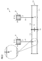
- Figure 2 shows a further embodiment of the pressure compensation system 100. Since figure 2 is a modification of the system illustrated in figure 1 , the explanations given above are equally applicable to the embodiment of figure 2 . In figure 2 , the measuring units and the control unit are not illustrated for the purpose of a clear presentation, yet they may certainly be present.
- the chamber 112 comprises (or is composed of) two compartments 113, 114, which are in flow communication during normal operation. Furthermore, a valve 115 is provided between the compartments, by means of which the flow connection between the compartments can be interrupted. The chamber 112 may thus be separated into two fluidically isolated compartments by closing valve 115.
- the flow connections 12, 22 each lead into a different compartment 113, 114. Accordingly, the flow communication between the pressure compensators 10, 20 can be interrupted by closing the valve 115.
- valves 13, 23 are located inside the compartments 113, 114, and thus within the chamber 112. They can thus be protected from the outside environment.
- the first and second biasing devices 19, 29 are in the embodiment of figure 2 provided in form of the end walls or top plates 15, 25 of the respective pressure compensators 10, 20.
- gravitational force will act to compress the respective bellows part 16, 26 and thus create the biasing and the desired overpressure in the medium filling the respective compensation volume. Accordingly, if one of the pressure compensators leaks, the loss of fluid and the gravitational force on the top plates 15, 25 will lead to the top plates moving downwards and compressing the bellows portion 16, 26. Again, such displacement of the pressure compensator can be measured by respective measuring units.
- each pressure compensator furthermore has a further end wall 17, 27.
- the flow connection 12, 22 is provided through this second end wall 17, 27.
- the dead volume of the respective pressure compensator can be kept low.
- the second end wall 17, 27 may abut a wall of the subsea enclosure 111, or may form part thereof, as illustrated in figure 1 .
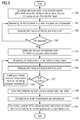
- FIG 3 shows a flow diagram of a method according to an embodiment of the invention.
- the method illustrated in figures 3 , 4 and 5 may be performed by the pressure compensation system 100 in any of the configurations described herein.
- step S10 the subsea pressure compensation system 100 is operated with the first valve 13 between the first pressure compensator 10 and the chamber 112 open and a second valve 23 between the second pressure compensator 20 and the chamber 112 closed.
- step 11 the displacement of the first pressure compensator 10 is measured, e.g. by measuring unit 61.
- step S12 the measured displacement is analyzed for a drift, e.g. by control unit 51. If in decision step S13, no drift is detected in the measured displacement, the method continues with step S11, i.e. the active pressure compensator 10 is continuously being monitored.
- step S14 determines that the first pressure compensator has failed. This determination can be performed by control unit 51.
- control unit 51 closes the first valve 13 and opens the second valve 23.
- at least one of the valves 13, 23 is kept open at any time so as to prevent the build-up of excessive negative or overpressure inside the chamber 112.
- the first pressure compensator 10 is isolated from the system, while the second pressure compensator 20 becomes active. Operation of the subsea pressure compensation system is continued in step S16.
- the pressure compensation system 100 is operable initially with both valves 13, 23 open.
- step S21 the displacement of the second pressure compensator is measured. Note that this may occur alternatively to the measurement of the displacement of the first pressure compensator, or the displacement of both pressure compensators may be measured.
- step S22 the measured displacement is analyzed for a drift, which may again be performed by control unit 51. If in step S23, no drift is detected, the method continues with step S21, i.e. the second pressure compensator is continuously being monitored. If in step S23, a drift is detected, it is determined by control unit 51 in step S24 that one of the pressure compensators has failed.
- Control unit 51 closes the first valve in step S25, thus closing the flow connection between the first and second pressure compensators.
- the displacement of the second pressure compensator 20 is measured in step S26, e.g. by measuring unit 62. If no drift is detected in decision step S27, control unit 51 can determine that the first pressure compensator has failed (step S28). Accordingly, since the first valve is already closed and the second valve 23 is opened, operation of the subsea pressure compensation system can continue in step S31, with the first pressure compensator being isolated.
- control unit 51 determines in step S29 that the second pressure compensator has failed. It further opens the first valve 13 and closes the second valve 23 in step S30. Operation is then continued in step S31, with the second pressure compensator 20 now being isolated, and first pressure compensator 10 being active.
- FIG. 5 is a flow diagram which illustrates a method that can be performed by a pressure compensation system that has two or more pressure compensators, e.g. three, four, five or more pressure compensators.
- the pressure compensation system 100 is operated with the fluid connection, in particular the valves, between the two or more pressure compensators and the chamber 112 open.
- all available pressure compensators may be active and thus in flow communication with chamber 112.
- the displacement of at least one pressure compensator is measured in step S41. This is sufficient since if one compensator fails, all compensators will show drift.
- step S42 the measured displacement is analyzed for drift. If no drift is detected in decision step S43, measuring the displacement and thus monitoring of the at least one pressure compensator is continued in step S41.
- step S44 one pressure compensator is isolated from the remaining pressure compensators, e.g. by closing the valve in the flow connection of the respective pressure compensator.
- each pressure compensator is provided with a measuring unit 61, 62.
- step S45 the displacement of the isolated compensator is measured and analyzed for a drift (step S46). If no drift is detected (decision step S47), a different pressure compensator of the remaining pressure compensators is isolated in step S48, and the method continues with step S45, thus measuring the displacement of the now isolated pressure compensator. This way, all pressure compensators are checked until the pressure compensator which is responsible for the drift is identified.
- step S49 If drift is detected in decision step S47, it is determined in step S49 that the now isolated pressure compensator has failed. If this is not already the case, then the valve of the failed pressure compensator is closed in step S50. Operation of the subsea pressure compensation system 100 can then continue in step S51 with the valves to the remaining pressure compensators being open. Even in a system comprising multiple pressure compensators, the method thus allows a fast and efficient detection of the location of a failed pressure compensator and the isolation thereof.
- the method may for example be modified by first checking the displacement of the pressure compensator equipment with the measuring unit, and if this pressure compensator is functional, connecting a fluid connection between these pressure compensators and the other pressure compensators, one after the other, so that the pressure compensator which is responsible for the drift can be identified.
- one pressure compensator after the other may be disconnected from chamber 112, and the location of the failed compensators may be determined by detecting in which configuration the displacement stops showing drift. The then isolated compensator will be the one that has failed.
- the detection schemes described with respect to figures 3-5 can be modified and combined with each other.
- the pressure compensation system 100 can be configured to perform any of the described methods.
Priority Applications (2)
| Application Number | Priority Date | Filing Date | Title |
|---|---|---|---|
| EP14162433.8A EP2924231A1 (fr) | 2014-03-28 | 2014-03-28 | Système de compensation de pression |
| US14/662,467 US9570224B2 (en) | 2014-03-28 | 2015-03-19 | Pressure compensation system |
Applications Claiming Priority (1)
| Application Number | Priority Date | Filing Date | Title |
|---|---|---|---|
| EP14162433.8A EP2924231A1 (fr) | 2014-03-28 | 2014-03-28 | Système de compensation de pression |
Publications (1)
| Publication Number | Publication Date |
|---|---|
| EP2924231A1 true EP2924231A1 (fr) | 2015-09-30 |
Family
ID=50391057
Family Applications (1)
| Application Number | Title | Priority Date | Filing Date |
|---|---|---|---|
| EP14162433.8A Withdrawn EP2924231A1 (fr) | 2014-03-28 | 2014-03-28 | Système de compensation de pression |
Country Status (2)
| Country | Link |
|---|---|
| US (1) | US9570224B2 (fr) |
| EP (1) | EP2924231A1 (fr) |
Cited By (4)
| Publication number | Priority date | Publication date | Assignee | Title |
|---|---|---|---|---|
| EP3121826A1 (fr) * | 2015-07-22 | 2017-01-25 | Siemens Aktiengesellschaft | Dispositif de rêception destinê à recevoir un liquide isolant |
| CN107401678A (zh) * | 2017-08-15 | 2017-11-28 | 中铁工程装备集团有限公司 | 全气动压力补偿控制系统 |
| EP3404198A1 (fr) * | 2017-05-19 | 2018-11-21 | ABB Schweiz AG | Agencement de refroidissement d'une installation sous-marine |
| CN114802661A (zh) * | 2022-04-13 | 2022-07-29 | 深圳市行健自动化股份有限公司 | 一种用于深海移动作业设备的耐压舱、水下采矿车和水下移动机器人 |
Families Citing this family (5)
| Publication number | Priority date | Publication date | Assignee | Title |
|---|---|---|---|---|
| NO343298B1 (en) * | 2015-07-03 | 2019-01-21 | Aker Solutions As | Annulus isolation valve assembly and associated method |
| US11143018B2 (en) | 2017-10-16 | 2021-10-12 | Halliburton Energy Services, Inc. | Environmental compensation system for downhole oilwell tools |
| EP3522688B1 (fr) * | 2018-02-06 | 2022-07-27 | ABB Schweiz AG | Système et procédé pour estimer la durée de vie utile restante d'un compensateur de pression |
| US10865899B2 (en) * | 2018-09-27 | 2020-12-15 | United States Of America As Represented By The Secretary Of The Navy | System and method for protecting a pressure vessel from excessive differential pressure |
| DE102018217369A1 (de) * | 2018-10-11 | 2020-04-16 | Robert Bosch Gmbh | Druckkompensationseinrichtung, eingerichtet für Anwendungen unter Wasser |
Citations (7)
| Publication number | Priority date | Publication date | Assignee | Title |
|---|---|---|---|---|
| WO2007055588A1 (fr) * | 2005-11-11 | 2007-05-18 | Norsk Hydro Produksjon A.S | Système de compensation antifuites |
| EP2169690A1 (fr) * | 2008-09-24 | 2010-03-31 | ABB Technology AG | Compensateur de pression |
| WO2011088840A1 (fr) | 2010-01-19 | 2011-07-28 | Siemens Aktiengesellschaft | Système de compensation de pression sous-marine |
| EP2571034A1 (fr) * | 2011-09-19 | 2013-03-20 | Siemens Aktiengesellschaft | Enceinte de transformateur sous-marin |
| EP2610881A1 (fr) * | 2011-12-28 | 2013-07-03 | Siemens Aktiengesellschaft | Compensateur de pression pour dispositif souterrain |
| EP2698610A1 (fr) | 2012-08-17 | 2014-02-19 | Siemens Aktiengesellschaft | Capteur de déplacement, en particulier pour une utilisation dans un dispositif sous-marin |
| EP2698611A1 (fr) | 2012-08-17 | 2014-02-19 | Siemens Aktiengesellschaft | Capteur de déplacement, en particulier pour une utilisation dans un dispositif sous-marin |
Family Cites Families (37)
| Publication number | Priority date | Publication date | Assignee | Title |
|---|---|---|---|---|
| GB1023452A (en) * | 1961-06-27 | 1966-03-23 | Bruce Peebles & Co Ltd | Oil conservator |
| US3163985A (en) * | 1962-07-31 | 1965-01-05 | John V Bouyoucos | Hydraulic energy storage system |
| US3330902A (en) * | 1964-07-14 | 1967-07-11 | Nakazawa Shinji | Conservator for oil-filled transformer |
| FR2090248B1 (fr) * | 1970-05-23 | 1974-08-02 | Pirelli | |
| US4095421A (en) * | 1976-01-26 | 1978-06-20 | Chevron Research Company | Subsea energy power supply |
| FR2418356A1 (fr) * | 1978-02-27 | 1979-09-21 | Gratzmuller Jean Louis | Accumulateur hydro-pneumatique a piston muni d'un dispositif detecteur de manque de gaz |
| US4167201A (en) * | 1978-04-03 | 1979-09-11 | Greer Hydraulics, Inc. | Pressure accumulator with failure indicator |
| GB2028003A (en) * | 1978-05-25 | 1980-02-27 | Brush Transformers Ltd | Liquid filled transformers |
| US4487226A (en) * | 1982-08-12 | 1984-12-11 | Vsi Corporation | Failure sensing hydraulic accumulator and system |
| GB9007210D0 (en) * | 1990-03-30 | 1990-05-30 | Loth William D | Improvements in or relating to subsea control systems and apparatus |
| GB2245038B (en) * | 1990-06-07 | 1994-03-23 | Toyota Motor Co Ltd | Device for detecting accumulator fluid leakage through control valve and restoring proper valve seating |
| JP3610272B2 (ja) * | 1999-11-29 | 2005-01-12 | 日本ピラー工業株式会社 | ベローズを有する流体機器 |
| EP1272764A2 (fr) * | 2000-04-04 | 2003-01-08 | Continental Teves AG & Co. oHG | Accumulateur d'agent de pression |
| JP3564362B2 (ja) * | 2000-05-10 | 2004-09-08 | 日本ピラー工業株式会社 | 脈動減衰装置 |
| JP3513096B2 (ja) * | 2000-09-25 | 2004-03-31 | トヨタ自動車株式会社 | アキュムレータおよびアキュムレータの異常検出装置 |
| EP1327080B1 (fr) * | 2000-10-11 | 2006-06-21 | Continental Teves AG & Co. oHG | Procede de remplissage d'un reservoir de fluide sous pression et dispositif pour la mise en oeuvre dudit procede |
| NO313068B1 (no) * | 2000-11-14 | 2002-08-05 | Abb As | Undersjoisk transformator - distribusjonssystem med et forste og et andre kammer |
| DE10207598A1 (de) * | 2001-02-23 | 2002-11-07 | Continental Teves Ag & Co Ohg | Druckmittelspeicher |
| JP4710159B2 (ja) * | 2001-04-09 | 2011-06-29 | 株式会社アドヴィックス | 加圧流体用ベローズ式アキュームレータの異常検出装置 |
| SE523397C2 (sv) * | 2001-05-22 | 2004-04-13 | Bruun Ecomate Ab | Mobil hanteringsanordning |
| DE10137988A1 (de) * | 2001-08-02 | 2003-02-13 | Continental Teves Ag & Co Ohg | Druckmittelspeicher |
| US6772794B2 (en) * | 2002-01-24 | 2004-08-10 | Seguin Carl | Variable volume reservoir |
| DE10236391B3 (de) * | 2002-08-08 | 2004-04-08 | Robert Bosch Gmbh | Verfahren zur Prüfung eines Druckmittelspeichers |
| DE10310428A1 (de) * | 2003-03-11 | 2004-09-30 | Hydac Technology Gmbh | Kolbenspeicher |
| BRPI0520625A2 (pt) * | 2005-10-19 | 2009-05-19 | Cameron Int Corp | equipamento submarino |
| GB2448529B (en) * | 2007-04-19 | 2011-08-31 | Subsea 7 Ltd | Protection system and method |
| US20080302115A1 (en) * | 2007-06-08 | 2008-12-11 | Coda Octopus Group, Inc. | Combined pressure compensator and cooling unit |
| EP2165081B1 (fr) * | 2007-06-14 | 2015-02-18 | Limo-Reid, Inc. | Accumulateur hydraulique compact |
| FR2930605B1 (fr) * | 2008-04-25 | 2015-01-16 | Airbus France | Procede de controle de l'etat d'un accumulateur a reserve d'energie, notamment pour aeronef. |
| NO328603B1 (no) * | 2008-05-14 | 2010-03-29 | Vetco Gray Scandinavia As | Undervanns hybrid ventilaktuatorsystem og fremgangsmate. |
| WO2010141605A1 (fr) * | 2009-06-03 | 2010-12-09 | Control Products Inc. | Accumulateur hydraulique avec capteur de position |
| NO331866B1 (no) * | 2010-05-20 | 2012-04-23 | Nat Oilwell Varco Norway As | Anordning og fremgangsmate for a gjenvinne hydraulisk energi |
| US8776511B2 (en) * | 2011-06-28 | 2014-07-15 | Caterpillar Inc. | Energy recovery system having accumulator and variable relief |
| DE102012205363A1 (de) * | 2012-04-02 | 2013-10-02 | Marco Systemanalyse Und Entwicklung Gmbh | Positionsbestimmungsvorrichtung |
| US20130284532A1 (en) * | 2012-04-25 | 2013-10-31 | Caterpillar Inc. | Secondary steering system with margin pressure detection |
| EP2660422A1 (fr) * | 2012-05-04 | 2013-11-06 | Siemens Aktiengesellschaft | Système de surveillance de position pour compensateurs à soufflet sous-marin |
| US20140060030A1 (en) * | 2012-08-31 | 2014-03-06 | Caterpillar Inc. | Hydraulic accumulator health monitor |
-
2014
- 2014-03-28 EP EP14162433.8A patent/EP2924231A1/fr not_active Withdrawn
-
2015
- 2015-03-19 US US14/662,467 patent/US9570224B2/en active Active
Patent Citations (9)
| Publication number | Priority date | Publication date | Assignee | Title |
|---|---|---|---|---|
| WO2007055588A1 (fr) * | 2005-11-11 | 2007-05-18 | Norsk Hydro Produksjon A.S | Système de compensation antifuites |
| EP2169690A1 (fr) * | 2008-09-24 | 2010-03-31 | ABB Technology AG | Compensateur de pression |
| WO2010034880A1 (fr) | 2008-09-24 | 2010-04-01 | Abb Technology Ag | Compensateur de pression |
| WO2011088840A1 (fr) | 2010-01-19 | 2011-07-28 | Siemens Aktiengesellschaft | Système de compensation de pression sous-marine |
| EP2571034A1 (fr) * | 2011-09-19 | 2013-03-20 | Siemens Aktiengesellschaft | Enceinte de transformateur sous-marin |
| EP2610881A1 (fr) * | 2011-12-28 | 2013-07-03 | Siemens Aktiengesellschaft | Compensateur de pression pour dispositif souterrain |
| US20130167962A1 (en) | 2011-12-28 | 2013-07-04 | Siemens Aktiengesellschaft | Pressure compensator for a subsea device |
| EP2698610A1 (fr) | 2012-08-17 | 2014-02-19 | Siemens Aktiengesellschaft | Capteur de déplacement, en particulier pour une utilisation dans un dispositif sous-marin |
| EP2698611A1 (fr) | 2012-08-17 | 2014-02-19 | Siemens Aktiengesellschaft | Capteur de déplacement, en particulier pour une utilisation dans un dispositif sous-marin |
Cited By (6)
| Publication number | Priority date | Publication date | Assignee | Title |
|---|---|---|---|---|
| EP3121826A1 (fr) * | 2015-07-22 | 2017-01-25 | Siemens Aktiengesellschaft | Dispositif de rêception destinê à recevoir un liquide isolant |
| EP3404198A1 (fr) * | 2017-05-19 | 2018-11-21 | ABB Schweiz AG | Agencement de refroidissement d'une installation sous-marine |
| CN107401678A (zh) * | 2017-08-15 | 2017-11-28 | 中铁工程装备集团有限公司 | 全气动压力补偿控制系统 |
| CN107401678B (zh) * | 2017-08-15 | 2023-04-25 | 中铁工程装备集团有限公司 | 全气动压力补偿控制系统 |
| CN114802661A (zh) * | 2022-04-13 | 2022-07-29 | 深圳市行健自动化股份有限公司 | 一种用于深海移动作业设备的耐压舱、水下采矿车和水下移动机器人 |
| CN114802661B (zh) * | 2022-04-13 | 2023-02-03 | 深圳市行健自动化股份有限公司 | 一种用于深海移动作业设备的耐压舱、水下采矿车和水下移动机器人 |
Also Published As
| Publication number | Publication date |
|---|---|
| US9570224B2 (en) | 2017-02-14 |
| US20150277452A1 (en) | 2015-10-01 |
Similar Documents
| Publication | Publication Date | Title |
|---|---|---|
| US9570224B2 (en) | Pressure compensation system | |
| US20170055356A1 (en) | Pressure compensator failure detection | |
| US10386005B2 (en) | Self-contained, fully mechanical, 1 out of 2 flowline protection system | |
| US10400905B2 (en) | Control device for controlling a valve arrangement and method for controlling a safety arrangement comprising said control device and said valve arrangement | |
| EP2501608B1 (fr) | Système de compensation de pression sous-marine | |
| US4230187A (en) | Methods and apparatus for sensing wellhead pressure | |
| US10677273B2 (en) | Subsea arrangement and method for detecting a malfunction of a subsea arrangement | |
| US11674529B2 (en) | Pressure compensation device designed for underwater applications | |
| WO2010034880A1 (fr) | Compensateur de pression | |
| US20160215913A1 (en) | Pressure compensator for subsea device | |
| WO2013163213A1 (fr) | Système et procédé pour surveiller une position à l'aide d'un capteur à ultrasons | |
| US9920852B2 (en) | Subsea electric actuator | |
| US11668149B2 (en) | Reliability assessable systems for actuating hydraulically actuated devices and related methods | |
| CN109690091A (zh) | 用于评估液压致动式装置的可靠性的方法及相关系统 | |
| NO326874B1 (no) | System og fremgangsmåte for overvåking av undersjøiske akkumulatorbanker | |
| EP3057111A1 (fr) | Compensateur de pression et procédé de fabrication d'un compensateur de pression | |
| WO2007055588A1 (fr) | Système de compensation antifuites | |
| AU2011339069B2 (en) | Method for condition monitoring of hydraulic accumulators | |
| NO20141416A1 (no) | Fremgangsmåte og system for regulering av fluid | |
| MX2013006829A (es) | Aparato y metodo para sistema de protección de alta integración para cabeza de pozo obturada. | |
| US11069156B2 (en) | System and method for estimating remaining useful life of pressure compensator | |
| RU2555927C2 (ru) | Система герметизации с компенсацией давления для вала вращения или перемещения | |
| KR102027491B1 (ko) | 바이메탈을 이용한 극저온 유체의 누출 감지 시스템 | |
| US10494881B2 (en) | Hoisting system | |
| NO337180B1 (no) | Overvåking av undervannspumpe- eller kompressorakslingstetning |
Legal Events
| Date | Code | Title | Description |
|---|---|---|---|
| PUAI | Public reference made under article 153(3) epc to a published international application that has entered the european phase |
Free format text: ORIGINAL CODE: 0009012 |
|
| AK | Designated contracting states |
Kind code of ref document: A1 Designated state(s): AL AT BE BG CH CY CZ DE DK EE ES FI FR GB GR HR HU IE IS IT LI LT LU LV MC MK MT NL NO PL PT RO RS SE SI SK SM TR |
|
| AX | Request for extension of the european patent |
Extension state: BA ME |
|
| 17P | Request for examination filed |
Effective date: 20160330 |
|
| RBV | Designated contracting states (corrected) |
Designated state(s): AL AT BE BG CH CY CZ DE DK EE ES FI FR GB GR HR HU IE IS IT LI LT LU LV MC MK MT NL NO PL PT RO RS SE SI SK SM TR |
|
| GRAP | Despatch of communication of intention to grant a patent |
Free format text: ORIGINAL CODE: EPIDOSNIGR1 |
|
| RIC1 | Information provided on ipc code assigned before grant |
Ipc: H05K 5/06 20060101ALI20170124BHEP Ipc: E21B 33/035 20060101AFI20170124BHEP Ipc: H01F 27/14 20060101ALI20170124BHEP Ipc: G05D 16/20 20060101ALI20170124BHEP Ipc: E21B 33/038 20060101ALI20170124BHEP |
|
| INTG | Intention to grant announced |
Effective date: 20170228 |
|
| RAP1 | Party data changed (applicant data changed or rights of an application transferred) |
Owner name: SIEMENS AKTIENGESELLSCHAFT |
|
| STAA | Information on the status of an ep patent application or granted ep patent |
Free format text: STATUS: THE APPLICATION IS DEEMED TO BE WITHDRAWN |
|
| 18D | Application deemed to be withdrawn |
Effective date: 20170711 |