EP2924207A1 - Gâchette - Google Patents
Gâchette Download PDFInfo
- Publication number
- EP2924207A1 EP2924207A1 EP15160221.6A EP15160221A EP2924207A1 EP 2924207 A1 EP2924207 A1 EP 2924207A1 EP 15160221 A EP15160221 A EP 15160221A EP 2924207 A1 EP2924207 A1 EP 2924207A1
- Authority
- EP
- European Patent Office
- Prior art keywords
- motor
- control input
- door
- housing
- designed
- Prior art date
- Legal status (The legal status is an assumption and is not a legal conclusion. Google has not performed a legal analysis and makes no representation as to the accuracy of the status listed.)
- Withdrawn
Links
Images


Classifications
-
- E—FIXED CONSTRUCTIONS
- E05—LOCKS; KEYS; WINDOW OR DOOR FITTINGS; SAFES
- E05B—LOCKS; ACCESSORIES THEREFOR; HANDCUFFS
- E05B63/00—Locks or fastenings with special structural characteristics
- E05B63/0065—Operating modes; Transformable to different operating modes
-
- E—FIXED CONSTRUCTIONS
- E05—LOCKS; KEYS; WINDOW OR DOOR FITTINGS; SAFES
- E05B—LOCKS; ACCESSORIES THEREFOR; HANDCUFFS
- E05B47/00—Operating or controlling locks or other fastening devices by electric or magnetic means
- E05B47/0046—Electric or magnetic means in the striker or on the frame; Operating or controlling the striker plate
- E05B47/0047—Striker rotating about an axis parallel to the wing edge
-
- E—FIXED CONSTRUCTIONS
- E05—LOCKS; KEYS; WINDOW OR DOOR FITTINGS; SAFES
- E05B—LOCKS; ACCESSORIES THEREFOR; HANDCUFFS
- E05B47/00—Operating or controlling locks or other fastening devices by electric or magnetic means
- E05B2047/0048—Circuits, feeding, monitoring
- E05B2047/0067—Monitoring
-
- E—FIXED CONSTRUCTIONS
- E05—LOCKS; KEYS; WINDOW OR DOOR FITTINGS; SAFES
- E05B—LOCKS; ACCESSORIES THEREFOR; HANDCUFFS
- E05B47/00—Operating or controlling locks or other fastening devices by electric or magnetic means
- E05B2047/0072—Operation
- E05B2047/0073—Current to unlock only
-
- E—FIXED CONSTRUCTIONS
- E05—LOCKS; KEYS; WINDOW OR DOOR FITTINGS; SAFES
- E05B—LOCKS; ACCESSORIES THEREFOR; HANDCUFFS
- E05B47/00—Operating or controlling locks or other fastening devices by electric or magnetic means
- E05B2047/0072—Operation
- E05B2047/0076—Current to lock only, i.e. "fail-safe"
-
- E—FIXED CONSTRUCTIONS
- E05—LOCKS; KEYS; WINDOW OR DOOR FITTINGS; SAFES
- E05B—LOCKS; ACCESSORIES THEREFOR; HANDCUFFS
- E05B47/00—Operating or controlling locks or other fastening devices by electric or magnetic means
- E05B2047/0084—Key or electric means; Emergency release
- E05B2047/0086—Emergency release, e.g. key or electromagnet
- E05B2047/0087—Electric spare devices, e.g. auxiliary batteries or capacitors for back up
-
- E—FIXED CONSTRUCTIONS
- E05—LOCKS; KEYS; WINDOW OR DOOR FITTINGS; SAFES
- E05B—LOCKS; ACCESSORIES THEREFOR; HANDCUFFS
- E05B47/00—Operating or controlling locks or other fastening devices by electric or magnetic means
- E05B2047/0094—Mechanical aspects of remotely controlled locks
-
- E—FIXED CONSTRUCTIONS
- E05—LOCKS; KEYS; WINDOW OR DOOR FITTINGS; SAFES
- E05B—LOCKS; ACCESSORIES THEREFOR; HANDCUFFS
- E05B47/00—Operating or controlling locks or other fastening devices by electric or magnetic means
- E05B47/06—Controlling mechanically-operated bolts by electro-magnetically-operated detents
- E05B47/0676—Controlling mechanically-operated bolts by electro-magnetically-operated detents by disconnecting the handle
Definitions
- the invention relates to a tumbler for holding a wing, a door or a window in a closed position according to the features of the preamble of claim 1.
- tumblers are known in practice. These known tumblers have an electrical actuator which is designed as a holding magnet or solenoid. Such as tumblers in escape doors, for example, in which a magnet cooperates with a metal plate to hold a wing of a door in the closed position, or even electric door opener.
- a locking device which has a drive motor for actuating a bolt.
- the locking device may be operated in only one of two modes, that is, operating in either a standby mode or in a working current mode.
- the tumbler has a control device which has a controllable from outside the housing control input and is designed so that it controls the motor so that the output device of the motor drives at energized control input in a first defined position and in de-energized control input to a second defined position moves and the control device is switched over a function control input so that the control device moves the motor with energized control input in the second defined position and at no-current control input to the second defined position.
- the function control input can be controlled via a switch arranged on a control board to ensure easy switching.
- the function control input is designed as a function control input which can be controlled from outside the housing, the function control input being designed as a voltage-controlled or current-controlled or potential-free controllable function control input.
- the function control input can be connected to a cable or controlled via a discrete cable connection. This allows convenient remote control of the guard locking, in particular the working current / quiescent current switching.
- the function control input is designed as a digital bus interface, in particular as a serial digital bus interface.
- the interlocking can be connected to a bus, in particular a CAN bus or an Ethernet bus or a LAN network via the bus interface. Via the bus a particularly comfortable and versatile control of the function control input is possible even over long distances.
- the function control input is connected to a wireless receiver and can be switched via a wireless connection. This will allow the Function control input is remotely controlled wirelessly.
- a wireless connection can serve an optical connection, such as an infrared connection or a high-frequency connection via a radio signal.
- the wireless receiver is designed as a WLAN interface or as a Bluetooth interface. This makes it possible for the function control input to be controllable via a WLAN-capable or Bluetooth-capable device, for example a tablet computer or a smartphone.
- the wireless receiver is arranged in or on the housing of the tumbler.
- the motor receives a significant amount of current primarily in the process from the first position to the second position or from the second position to the first position.
- the current consumption of the control device is relatively low compared to the current consumption of an engine.
- the actuators known from the prior art constantly receive current during their entire switch-on period.
- the power consumption is significantly reduced in the tumbler according to the invention.
- the tumbler according to the invention makes it possible with the control device to perform a control according to the proven working current principle and closed-circuit principle, as it already exists in many existing installations.
- the control device translates a working current / quiescent current control of a conventional monostable actuator into a motor control, in particular into a motor control Position control or position control of an engine.
- Position control or position control means that the motor is controlled by the controller to reach a predetermined position, ie a predetermined position or position.
- the tumbler for holding a wing of a door or a window in a closed position has a housing in which an electric motor is arranged with an output device.
- the motor or the output device is connected to a movably mounted in the housing component and / or a movably mounted in the housing locking element and / or movably mounted in the housing latch bolt with inlet slope, and / or movably mounted in the housing door latch latch and drives it.
- a control device for controlling the electric motor is provided.
- the output device of the engine can be designed as a transmission, in particular lever gear or gear transmission or as a spindle gear.
- the housing of the tumbler may be formed as a structural housing to attach the tumbler, for example, resting on a stationary frame of a door or a window.
- the housing of the tumbler may be formed in a different embodiment as a built-in housing to install within the stationary frame of a door or a window in a corresponding receiving pocket.
- the locking element can be designed as a linearly movable bolt or as a pivot bolt or as a hook bolt.
- the latch may be formed as Kippfalle or as a cross latch or spring-loaded latch with an inlet slope.
- the door opener latch can be configured as a latchable or releasable latch via a blocking device to hold a wing of a door or window in its closed position.
- control input is designed such that the control device is supplied with power via the control input.
- the control device has an electrical energy storage, which is designed so that it takes over the power supply of the control device and / or the motor when de-energized control input.
- the electrical energy store can be configured as a rechargeable battery or as a capacitor. It is envisaged that the capacity of the energy store is at least large enough that at least one change of position of the motor with the stored in the energy storage electric charge is possible. It can further be provided that the control device is designed to charge the energy store via the control input.
- control device has a separate power supply input, which is designed such that the power supply input supplies power to the control device and / or the motor.
- the control input can be connected to a battery, a battery or an external power supply, for example.
- the control device has a sensor device which detects a position of the motor or its output device.
- the sensor device can be designed, for example, as an optical or inductive sensor device.
- the control device can have two sensors, wherein the first sensor monitors the first defined position of the engine and / or the output device and the second sensor monitors the second defined position of the engine and / or the output device.
- a compact design can be achieved in one embodiment by the control device and the two sensors are arranged together on a control board and it is preferably provided that the control board is disposed completely within the housing.
- the motor is designed as a servomotor or as a stepper motor.
- the control device controls the servomotor or the stepping motor so that no additional sensors for detecting the position of the motor are necessary because the servo motor of the control device automatically returns its position, or the stepping motor is controlled by a sequence of steps whose frequency includes a direct measure of the distance traveled by the stepper motor.
- control device energizes the motor only for moving into the first defined position or the second defined position and switches the motor de-energized after reaching the first defined position or the second defined position.
- first defined position and / or the second defined position are each an end position.
- the control device carries out a reference run of the motor when neither a signal of the first sensor nor a signal of the second sensor is present. It can further be provided that the control device outputs an error signal if no sensor signal is present during or after the reference run. Likewise, for example, the control device output an error signal when a signal of both sensors is present at the same time.
- a possible universal adaptation of the tumbler results by providing in one embodiment that the control device has a function control input via which it is possible to switch over whether the control device drives the motor when the control input is energized in the first defined position or in the second defined position.
- the function control input via a on the control board arranged switch can be controlled.
- the switch can be designed as a dip switch or as a toggle switch.
- the tumbler is designed as a door opener with a door opener trap, the door opener trap via an anchor and / or a change in a first position of the armature and / or the change lockable and in a second position of the armature and / or the change is releasable, and the motor via its output device drives the anchor and / or the change to lock or release the trap.
- a realization of a panic function for forming a panic lock can be implemented by providing in one embodiment that the nut is designed as a multi-part nut having a first outer nut and a second outer nut and the coupling device for coupling optionally the first outer nut and / or the second outer nut connects with the locking device.
- An application of the tumbler according to the invention can be carried out in particular in doors or windows in buildings or vehicles or to secure security areas, especially as guard locking of escape route security systems.
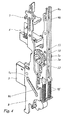
- the Fig. 1 to 7 To illustrate the principle of operation of a tumbler and the basic functions of a guard locking exclusively mechanically operated door lock 1.
- the tumbler is intended as a door lock for so-called panic doors.
- the door lock 1 is described for clarity without the arranged on a board sensors and without the electrical actuators as a mechanical lock.
- the lock In the FIGS. 8 to 9 the lock is described in a variant with sensors and an electric motor, which acts as an electric actuator.
- Door locks for panic doors are designed so that, in the event of danger, they allow leaving a room closed by the panic door, even if the door lock 1 is locked.
- the door lock 1 has a face plate 2, which is provided for fastening the door lock 1 on the front side of the panic door and serves as a frame for other lock parts (see Fig. 1 and 2 ).
- the door lock 1 comprises a lock mechanism with a bolt 3, a latch 4, an auxiliary latch 5, a lock nut 6 and a lock cylinder 7.
- the lock nut 6 comprises a first outer nut 6a and a second outer nut 6b.
- the latch 3, the latch 4 and the auxiliary latch 5 are retractable in the faceplate 2 to open the panic door or extendable from the forend 2 to close the panic door.
- the bolt 3 can be actuated by a bolt slide 8, wherein the bolt 3 is coupled via a sliding gear with the bolt slide 8.
- the bolt slide 8 has a Z-shaped gate 8k, in the one with the bolt 3 rigidly connected pin 3z slides.
- the locking slide 8 is designed to be displaceable parallel to the longitudinal axis of the forend 2. Since the actuation direction of the bolt 3 is perpendicular to the longitudinal axes of the end portions of the link 8k, the bolt 3 is no longer displaceable when the pin 3z of the bolt 3 in a the two end portions of the gate 8k is arranged. As soon as the pin 3z enters the oblique center section of the gate 8k by displacing the bolt slide 8, the bolt 3 is retracted or extended into the forend 2 until it again enters an end section of the gate 8k and is thus locked.
- the bolt slide 8 can be actuated both by the lock cylinder 7 and by the lock nut 6.
- the lock cylinder 7 engages with its center portion of the door lock 1 and with its end portions opposing receptacles in the door leaves of the panic door.
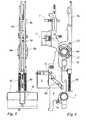
- the designed as a one-armed lever core 7k of the lock cylinder 7 is pivotable by key engagement about the longitudinal axis of the lock cylinder 7, wherein the end portion of the core 7k cooperates with the locking slide 8, such as in Fig. 6 is recognizable.
- the core 7k is rotated by inserting a suitable key into the lock cylinder 7 (in FIG Fig.
- the bolt slide 8 is raised, so that the pin 3z of the bolt 3 enters the oblique center portion of the link 8k, the bolt 3 is retracted into the forend 2 until the pin 3z enters the other end portion of the link 8k , And thus the bolt 3 is locked in the retracted position in the faceplate 2.
- the outer nuts 6a, 6b of the lock nut 6 cooperate with slide-shaped coupling elements, wherein the first outer nut 6a cooperates with a first coupling element 9a and the second outer nut 6b with a second coupling element 9b.
- the coupling elements 9a, 9b are by compression springs 9f (see Fig. 3 to 6 ), which are supported on the frame of the door lock 1, pressed into an upper end position.
- the coupling elements 9a, 9b like the locking slide 8, are designed to be displaceable parallel to the longitudinal axis of the forend 2 and have, as in FIG Fig. 3a shown, a coupling recess 9k, in which a arranged on the rear outer circumference of the outer nut 6a, 6b driver 6m attacks.
- a transmission element is arranged, which is designed as an intermediate slide 10, which cooperates via a pivotable coupling member 11 with the locking slide 8.
- the intermediate slide 10 is optionally rigidly connectable to the first coupling element 9a or to the second coupling element 9b.
- connecting elements connecting screws 12 may be provided which engage in the intermediate slide 10 by cross threaded holes.
- the Fig. 7a and 7b show a variant of in Fig. 1 to 6 described door lock 1, in which a modified intermediate slide 10 is inserted.
- a pawl 10s is rotatably mounted, which is on and auskoppelbar.
- the pawl 10s is brought into the disengaged state by a return spring 10sf.
- the return spring 10sf is formed as a compression spring and arranged between pawl 10s and the intermediate slide 10.
- the pawl 10s connects in the coupled state, the first coupling element 9a and / or the second coupling element 9b at least in a direction of movement, preferably in the unlocking, firmly with the intermediate slide 10.
- the pawl 10s engages behind for coupling to the first coupling element 9a and / or the second Clutch 9b trained undercut 9h. It can also be provided that the pawl 10s engages for coupling into a groove formed on the first coupling element 9a and / or the second coupling element 9b. It is thus possible to realize an access function of an authorized person by connecting the coupling device for coupling the intermediate slide 10 with the first coupling element 9a and / or the second coupling element 9b and for decoupling the intermediate slide 10 of the first coupling element 9a and / or of the second coupling element 9b triggers.
- the panic door in case of danger, for example, in the event of a fire, automatically unlocked.
- the pawl 10s is actuated by a Sch thoroughlyzylinderzug 7z.
- the Sch thoroughlyzylinderzug 7z is formed as a two-armed lever which is mounted in the housing of the door opener 1.
- a bearing axis 7zl is shown, around which the Sch thoroughlyzylinderzug 7z pivotally is.
- the one lever arm of the Sch thoroughlyzylinderzugs 7z has a switching cam 7zs on with a straight portion which merges into a circular arc, the other lever arm has at its end portion a switching lug 7zn, which rests in the coupled state on the pawl 10s.
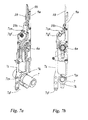
- the 8 and 9 show a first embodiment of the tumbler according to the invention as a door lock 1, which on the in Fig. 1 to 7 builds up the described principle of action.
- the door lock 1 has optical sensors L1 to L7 and Hall sensors H1 and H2, which are arranged on a circuit board 16. On the board 16, an electronic control device 17 is further arranged, which is connected to the sensors and an actuator 13 drives.
- the optical sensors L1 to L7 are designed as bifurcated light barriers, which are switchable by a slide switch.
- the slide switch When the slide switch is inserted into the light barrier, the light barrier is activated, ie the optical sensor is active.
- the slide switch in the photocell When the slide switch in the photocell is not immersed, the photocell is unconfirmed, ie the optical sensor is inactive.
- An auxiliary case sensor L6 cooperates with a switch 5s arranged on the auxiliary latch 5.
- a door contact sensor L7 cooperates with a switch 15s arranged on the door contact 15.
- the door lock 1 has a first slide sensor L3, a second slide sensor L4 and a third slide sensor L5, which can be switched by a switch slide 8s arranged on the latch slide 8.
- the slider sensors L3 to L5 are arranged in the direction of movement of the slide valve 8s one behind the other and spaced from each other on the circuit board 16.
- the slide switch 8s is designed to co-operate with a maximum of two of the three slide sensors L3 to L5. Since the bolt 3 is motion-coupled to the bolt slide 8 by a link gear, describe the signals of the slide sensors L3 to L5, the position of the bolt. 3
- the door lock 1 on a Nusssensor L1 with the lock nut 6 for detecting a movement of a in Fig. 7 and 8th not shown and designed as an external handle handle cooperates.
- a switching slide 9s cooperates, which is connected to the second coupling element 9b.
- the second outer nut 6b is coupled to the second coupling element 9b, is moved linearly upon rotation of the second outer nut 6b of the slide switch 9s.
- the door lock 1 further comprises a bolt sensor L2, which with the lock nut 6 for detecting a movement of a in Fig. 7 and 8th not shown and designed as an internal handle handle cooperates.
- a bolt sensor L2 acts a slide switch 9as, which is connected to the first coupling element 9a.
- the first outer nut 6a is motion-coupled to the first coupling element 9a, 9a is moved linearly upon rotation of the first outer nut 6a of the slide switch.
- the door lock 1 has a coupling device for coupling the two handles.
- the coupling device comprises a coupling lever 13k. It is driven by an electric actuator which is designed as a control motor 13.
- the engine 13 has an output device 13s, which actuates the clutch lever 13k.
- the output shaft of the electric control motor 13 is rotatably connected to the output device 13s.
- the output device 13s acts on a first leg of the clutch lever 13k configured as an angle lever.
- a second leg of the clutch lever 13k cooperates with a pawl 10s, which is rotatably mounted on the intermediate slide 10.
- the pawl 10s connects in the coupled state, the first coupling element 9a and / or the second coupling element 9b of the coupling device at least in one direction, preferably in the unlocking, firmly with the intermediate slide 10.
- the pawl 10s engages behind for coupling to the first coupling element 9a and / or The undercut 9h formed in the second coupling element 9b. It can also be provided that the pawl 10s engages for coupling into a groove formed on the first coupling element 9a and / or the second coupling element 9b.
- the coupling device for coupling connects the intermediate slide 10 with the first coupling element 9a and / or the second coupling element 9b and for decoupling the intermediate slide 10 of the first coupling element 9a and / or of the second coupling element 9b solves.
- the panic door in case of danger, for example, in the event of a fire, automatically unlocked.
- a first position sensor H1 and a second position sensor H2 are arranged in the area of the output device 13s.
- the position sensors H1 and H2 are designed as Hall sensors, which are switched by a arranged on the output of the output device 13s permanent magnet.
- the position sensor H1, H2 is active or actuated when the permanent magnet is above the position sensor H1, H2.
- the position sensor H1, H2 is inactive or inoperative when the permanent magnet is not above the position sensor H1, H2.
- a control device 17 is arranged, which cooperates with the position sensors H1 and H1 for detecting the position of the output device 13s.
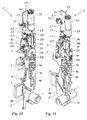
- the 10 and 11 show a second embodiment of the tumbler according to the invention as a door lock. 1
- the door lock 1 is like the one in 8 and 9 described door lock, with the difference that the door lock 1 is formed as a motor lock.
- an electric drive motor 14 which actuates the latch 3 via a driven device, comprising a cam disc 18 and a locking slide 8.
- the cam disk 18 has at its end face a cylindrical contact piece 18 s, which in a rotation of the cam disc 18 by about 180 ° in the clockwise direction from its in Fig. 9 and 10 illustrated starting position the bolt slide 8 lifts and thereby pulls the bolt 3 in the forend 2.
- the switch piece 18s is in an upper position, and the door can be opened.
- the position of the switching piece 18s is transmitted via a two-armed cam lever 19, wherein the cam lever 19 at its cam lever 18 facing away from the lever arm has a switching piece 18s, which cooperates with a motor position sensor L8.
- the engine position sensor L8 is electrically connected to the electronic control device 17.
- the control device 17 detects a position of the motor and thus indirectly monitors the locking position of the bolt 3 in order to detect a locking position of the bolt 3 and / or an unlocking position of the bolt 3.
- a bolt sensor L2 ' acts like the one in Fig. 7 and 8th described bolt sensor L2 with the lock nut 6 for detecting a movement of a in Fig. 9 and 10 not shown and designed as an internal handle handle together.
- the movement is transmitted via a pivot lever 20 mounted in the bearing of the cam lever 19.
- the pivot lever 20 has at its end remote from the bearing on a switching piece 20s, which cooperates with the bolt sensor L2 '.
- the Fig. 12 shows the tumbler 1 in a further embodiment, wherein the tumbler is designed as a door opener.
- the door opener 1 has a door opener housing 411, which is formed substantially cuboid.
- the door opener housing 411 has a removable lid 412, which covers a space of the door opener housing.
- components of the door opener such as a blocking device and a movably mounted door latch 14 are added.
- the door opener 1 can be installed in a fixed frame of a door or a grand piano. It can be installed in particular in a lock counter box or connected to a strike plate.
- the door opener housing 411 has two attachment openings 413a and 413b on its front side. These are in the representation of Fig. 12 left and right of the door opener 411 pivotally mounted in the door opener housing 411 arranged.
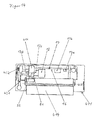
- the tumbler 1 and the door opener is shown in a plan view, with the cover 412 of the door opener has been removed for clarity.
- a blocking device is accommodated, which has a movably mounted armature 421 and an armature 421 movably mounted with this also movably mounted change 424.
- the change 424 is connected between the movable armature 421 and the door opener latch 414.
- the door opener latch 414 is movably mounted about a pivot axis 415 in the housing 411 of the tumbler.
- the change 424 is acted upon by a spring and is located directly on the movable door latch.
- the movable armature 421 is pivoted into the range of movement of the change 424.
- the armature 421 has a projection, with which he in the Fig. 13 shown Position one end face of the change 424 overlaps and this fixed in the applied to the door latch 414 position. As a result, the door opener latch 414 is locked and can not be pivoted.
- an armature spring 422 is provided, which is formed as a compression spring and acts between the door opener housing 411 and the armature 421 to bias the armature 421 in the locking position.
- the armature 421 is driven by a motor 13, which in the illustration of Fig. 14 is shown.
- the Fig. 14 shows a plan view of the door opener housing, in which not only the lid 412 but other components, such as the change 424 have been omitted to illustrate the arrangement of the other components.
- a motor 13 which acts on the armature 421 via an output device 13s and a linear push rod 13sk.
- a control device 17 is arranged on a circuit board 16 parallel to the pivot axis 415 of the door opener latch. The control device 17 controls the motor 13 such that the output device 13s of the motor 13 moves the armature 421 to a first position corresponding to a locked position of the door opener latch 14 or to a second position corresponding to a released position of the door opener latch 14 ,
- the control device 17 has a control input 17a, which is likewise arranged on the circuit board 16.
- the control device controls the motor so that the armature 21 is moved to the unlocked position.
- the control device controls the motor so that the motor is in the locked position is driven.
- the armature spring 422 assists the engine 13 in the locked position.
- the tumbler 1 is designed similar to a door opener, which operates on the working current principle.
- control device 17 controls the motor 13 so that when energized control input 17a, the armature 421 is moved to the locked position.
- control input 17a When the control input 17a is de-energized, the armature 421 is moved via the motor 13 into the unlocked position.
- the control device 17 is supplied with power via the control input 17a.
- an energy storage 17b is charged, which is also arranged on the board 16, and the control device 17 and the motor 13 is supplied with power.
- the capacity of the energy accumulator is sized so that it is sufficient to supply the control device 17 and the motor 13 so long that at least one change of position of the engine is executable.
- the energy storage 17b is formed as a capacitor having a high capacity, wherein it has been found that a gold cap meets these requirements.
- the control device 17 is connected to a sensor device 416.
- the sensor device 416 has two sensors H1 and H2 which are arranged on the output device 13s and are configured such that the first sensor H1 detects the first position of the output device and the sensor H2 detects the second position of the output device.
- the first position corresponds to a first end position of the armature that corresponds to the locked position of the door opener latch 414.
- the second position of the output device corresponds to a second end position corresponding to the unlocked position of the door opener latch 414.
- the control device can be connected via the control input 17a with a higher-level control center, or be connected in a simple embodiment via a door opener with a corresponding power supply. Due to the fact that the control device 17 controls the motor according to the working current or closed-circuit current principle, the tumbler 1 can easily be installed or retrofitted into existing installations. In particular, conventional door openers can be exchanged for the tumbler 1 according to the invention.
Landscapes
- Engineering & Computer Science (AREA)
- Structural Engineering (AREA)
- Lock And Its Accessories (AREA)
Applications Claiming Priority (1)
| Application Number | Priority Date | Filing Date | Title |
|---|---|---|---|
| DE102014104128.3A DE102014104128B4 (de) | 2014-03-25 | 2014-03-25 | Zuhaltung |
Publications (1)
| Publication Number | Publication Date |
|---|---|
| EP2924207A1 true EP2924207A1 (fr) | 2015-09-30 |
Family
ID=52706050
Family Applications (1)
| Application Number | Title | Priority Date | Filing Date |
|---|---|---|---|
| EP15160221.6A Withdrawn EP2924207A1 (fr) | 2014-03-25 | 2015-03-23 | Gâchette |
Country Status (2)
| Country | Link |
|---|---|
| EP (1) | EP2924207A1 (fr) |
| DE (2) | DE102014104128B4 (fr) |
Families Citing this family (4)
| Publication number | Priority date | Publication date | Assignee | Title |
|---|---|---|---|---|
| DE102016207937C5 (de) * | 2016-05-09 | 2023-12-07 | Geze Gmbh | Schloss mit mehreren Verriegelungselementen |
| DE102016207939B4 (de) * | 2016-05-09 | 2020-05-28 | Geze Gmbh | Schloss für einen schwenkbaren Flügel |
| DE102016207938A1 (de) * | 2016-05-09 | 2017-11-09 | Geze Gmbh | Schloss für einen schwenkbaren Flügel |
| DE102022132983B3 (de) | 2022-12-12 | 2024-02-15 | ASTRA Gesellschaft für Asset Management mbH & Co. KG | Türöffner |
Citations (6)
| Publication number | Priority date | Publication date | Assignee | Title |
|---|---|---|---|---|
| DE19534609A1 (de) * | 1995-09-18 | 1997-05-15 | Fuss Fritz Gmbh & Co | Selbstverriegelndes Motorschloss |
| WO1999034079A1 (fr) * | 1997-12-24 | 1999-07-08 | Loktronic Industries Limited | Serrure electrique |
| WO2005042886A1 (fr) * | 2003-10-30 | 2005-05-12 | Abloy Oy | Serrure de porte a commande de fonctionnement de la poignee |
| WO2005064104A1 (fr) * | 2003-12-20 | 2005-07-14 | Assa Abloy Sicherheitstechnik Gmbh | Gache a commande electrique |
| WO2011160161A1 (fr) * | 2010-06-23 | 2011-12-29 | Fire & Security Hardware Pty Ltd | Mécanisme de verrouillage |
| WO2012155177A1 (fr) | 2011-05-16 | 2012-11-22 | Fire & Security Hardware Pty Ltd | Dispositif de verrouillage |
Family Cites Families (2)
| Publication number | Priority date | Publication date | Assignee | Title |
|---|---|---|---|---|
| WO2012006658A1 (fr) * | 2010-07-15 | 2012-01-19 | Gainsborough Hardware Industries Limited | Ensemble serrure |
| DE102011051946A1 (de) * | 2011-07-19 | 2013-01-24 | Dorma Gmbh + Co. Kg | Türöffner mit Mitteln zur Erfassung der Position von beweglichen Bauteilen des Türöffners |
-
2014
- 2014-03-25 DE DE102014104128.3A patent/DE102014104128B4/de active Active
-
2015
- 2015-03-23 EP EP15160221.6A patent/EP2924207A1/fr not_active Withdrawn
- 2015-03-23 DE DE202015008999.2U patent/DE202015008999U1/de not_active Expired - Lifetime
Patent Citations (6)
| Publication number | Priority date | Publication date | Assignee | Title |
|---|---|---|---|---|
| DE19534609A1 (de) * | 1995-09-18 | 1997-05-15 | Fuss Fritz Gmbh & Co | Selbstverriegelndes Motorschloss |
| WO1999034079A1 (fr) * | 1997-12-24 | 1999-07-08 | Loktronic Industries Limited | Serrure electrique |
| WO2005042886A1 (fr) * | 2003-10-30 | 2005-05-12 | Abloy Oy | Serrure de porte a commande de fonctionnement de la poignee |
| WO2005064104A1 (fr) * | 2003-12-20 | 2005-07-14 | Assa Abloy Sicherheitstechnik Gmbh | Gache a commande electrique |
| WO2011160161A1 (fr) * | 2010-06-23 | 2011-12-29 | Fire & Security Hardware Pty Ltd | Mécanisme de verrouillage |
| WO2012155177A1 (fr) | 2011-05-16 | 2012-11-22 | Fire & Security Hardware Pty Ltd | Dispositif de verrouillage |
Also Published As
| Publication number | Publication date |
|---|---|
| DE202015008999U1 (de) | 2016-06-09 |
| DE102014104128B4 (de) | 2018-10-31 |
| DE102014104128A1 (de) | 2015-10-01 |
Similar Documents
| Publication | Publication Date | Title |
|---|---|---|
| EP1842989B1 (fr) | Serrure à mortaiser | |
| EP3219886B1 (fr) | Barre de poussée comprenant un dispositif d'entraînement | |
| EP1292747A1 (fr) | Serrure a verrouillage automatique et systeme de fermeture comportant une telle serrure | |
| EP1283318A1 (fr) | Dispositif de verrouillage | |
| DE102013202475A1 (de) | Verriegelungsbetätigungssystem und benachrichtigungsverfahren | |
| EP2754794A2 (fr) | Dispositif d'embrayage | |
| EP2924202A1 (fr) | Serrure de porte ou de fenêtre | |
| EP2924207A1 (fr) | Gâchette | |
| DE102008048395A1 (de) | Schließanlage | |
| DE202011108234U1 (de) | Selbstverriegelndes Fallenschloss | |
| DE102011051952A1 (de) | Fernaktivierbares selbstverriegelndes Türschloss | |
| EP3126597B1 (fr) | Serrure pour porte ou fenêtre | |
| EP3543439B1 (fr) | Procédé pour un ensemble serrure | |
| EP3219885B1 (fr) | Barre de poussée comprenant un dispositif d'entraînement modulaire | |
| EP2924201A1 (fr) | Serrure de porte ou de fenêtre | |
| EP2520746B1 (fr) | Serrure actionnée de manière électrique | |
| EP2816181B1 (fr) | Serrure de porte | |
| EP3219887B1 (fr) | Barre de poussée | |
| DE10122466C2 (de) | Schloß | |
| EP3452677B1 (fr) | Bascule de renvoi servant à actionner un pêne pivotant d'une porte coulissante de véhicule | |
| DE202015104480U1 (de) | Kompaktes selbstverriegelndes Einsteckschloss | |
| DE102013212514A1 (de) | Türanlage | |
| EP2924206B1 (fr) | Serrure de porte ou de fenêtre | |
| DE202023000829U1 (de) | Schließvorrichtung, Gegenkasten, System mit einer Schließvorrichtung und Schlossanordnung | |
| DE102022134993A1 (de) | Antipanikschloss mit Fluchttüröffner |
Legal Events
| Date | Code | Title | Description |
|---|---|---|---|
| PUAI | Public reference made under article 153(3) epc to a published international application that has entered the european phase |
Free format text: ORIGINAL CODE: 0009012 |
|
| AK | Designated contracting states |
Kind code of ref document: A1 Designated state(s): AL AT BE BG CH CY CZ DE DK EE ES FI FR GB GR HR HU IE IS IT LI LT LU LV MC MK MT NL NO PL PT RO RS SE SI SK SM TR |
|
| AX | Request for extension of the european patent |
Extension state: BA ME |
|
| STAA | Information on the status of an ep patent application or granted ep patent |
Free format text: STATUS: THE APPLICATION IS DEEMED TO BE WITHDRAWN |
|
| 18D | Application deemed to be withdrawn |
Effective date: 20160331 |