EP2924203A1 - Griff für eine Tür von einem Schaltschrank und Schaltschrank - Google Patents
Griff für eine Tür von einem Schaltschrank und Schaltschrank Download PDFInfo
- Publication number
- EP2924203A1 EP2924203A1 EP14004066.8A EP14004066A EP2924203A1 EP 2924203 A1 EP2924203 A1 EP 2924203A1 EP 14004066 A EP14004066 A EP 14004066A EP 2924203 A1 EP2924203 A1 EP 2924203A1
- Authority
- EP
- European Patent Office
- Prior art keywords
- handle
- main body
- latch
- door
- cabinet
- Prior art date
- Legal status (The legal status is an assumption and is not a legal conclusion. Google has not performed a legal analysis and makes no representation as to the accuracy of the status listed.)
- Withdrawn
Links
Images


Classifications
-
- E—FIXED CONSTRUCTIONS
- E05—LOCKS; KEYS; WINDOW OR DOOR FITTINGS; SAFES
- E05B—LOCKS; ACCESSORIES THEREFOR; HANDCUFFS
- E05B1/00—Knobs or handles for wings; Knobs, handles, or press buttons for locks or latches on wings
- E05B1/0015—Knobs or handles which do not operate the bolt or lock, e.g. non-movable; Mounting thereof
-
- E—FIXED CONSTRUCTIONS
- E05—LOCKS; KEYS; WINDOW OR DOOR FITTINGS; SAFES
- E05B—LOCKS; ACCESSORIES THEREFOR; HANDCUFFS
- E05B15/00—Other details of locks; Parts for engagement by bolts of fastening devices
- E05B15/02—Striking-plates; Keepers; Bolt staples; Escutcheons
-
- E—FIXED CONSTRUCTIONS
- E05—LOCKS; KEYS; WINDOW OR DOOR FITTINGS; SAFES
- E05B—LOCKS; ACCESSORIES THEREFOR; HANDCUFFS
- E05B17/00—Accessories in connection with locks
- E05B17/14—Closures or guards for keyholes
- E05B17/18—Closures or guards for keyholes shaped as lids or slides
- E05B17/183—Closures or guards for keyholes shaped as lids or slides pivoting outwardly
-
- E—FIXED CONSTRUCTIONS
- E05—LOCKS; KEYS; WINDOW OR DOOR FITTINGS; SAFES
- E05C—BOLTS OR FASTENING DEVICES FOR WINGS, SPECIALLY FOR DOORS OR WINDOWS
- E05C3/00—Fastening devices with bolts moving pivotally or rotatively
- E05C3/02—Fastening devices with bolts moving pivotally or rotatively without latching action
- E05C3/04—Fastening devices with bolts moving pivotally or rotatively without latching action with operating handle or equivalent member rigid with the bolt
- E05C3/041—Fastening devices with bolts moving pivotally or rotatively without latching action with operating handle or equivalent member rigid with the bolt rotating about an axis perpendicular to the surface on which the fastener is mounted
- E05C3/042—Fastening devices with bolts moving pivotally or rotatively without latching action with operating handle or equivalent member rigid with the bolt rotating about an axis perpendicular to the surface on which the fastener is mounted the handle being at one side, the bolt at the other side or inside the wing
-
- H—ELECTRICITY
- H02—GENERATION; CONVERSION OR DISTRIBUTION OF ELECTRIC POWER
- H02B—BOARDS, SUBSTATIONS OR SWITCHING ARRANGEMENTS FOR THE SUPPLY OR DISTRIBUTION OF ELECTRIC POWER
- H02B1/00—Frameworks, boards, panels, desks, casings; Details of substations or switching arrangements
- H02B1/26—Casings; Parts thereof or accessories therefor
- H02B1/30—Cabinet-type casings; Parts thereof or accessories therefor
- H02B1/38—Hinged covers or doors
Definitions
- the invention is about a handle for a door of an electrical cabinet or box, including a handle element in the form of a flap, said handle element being located on a frame-like main body in such a manner that it can be pivoted, wherein the main body can be attached in recesses in the door by means of latch means, according to the preamble of claim 1.
- a door handle, respectively lid handle, for electrical cabinets or boxes is described in DE 298 04 457 U1 .
- a spring-loaded latch is being aligned perpendicularly to the plane of the main body and is rigidly fixed on the main body in the area of attachment of the handle element, and the latch includes a latch projection which acts in conjunction with a part of the cabinet or box to hold the door or lid in a closed position.
- a pre-punched hole foreseen in which a lock can be inserted, if required.
- the lock has a bolt which in its locked position would make contact with the latch in such a way that the latch cannot be pivoted, so that the door cannot be opened in the locked position of the lock.
- handle element and main body are assembled before insertion into the door, which makes the handle assembly un-easy and has an inherent risk of disrupting the assembled handle structure on fixing it to the door.
- the locking bolt may be bent aside from the latch and release the latch so that the door could be opened despite the lock being in the locked position.
- an attachment part in the form of a hollow cylinder being aligned perpendicularly to the plane of the main body, wherein in the main body, in the area covered by the handle element when the latter is flapped down, a hole is provided for the installation of a lock into the hollow cylinder, and wherein at the wall of the hollow-cylinder-shaped attachment part a latch projection is provided which acts in conjunction with a springy holding part of the cabinet or box to hold the door in a closed position.
- the hollow cylinder gives stability and robustness to the handle design and lowers the risk of disrupting it during the process of attaching it to the door. Furthermore, as a lock, if required, will be inserted into the hollow-cylinder-shaped attachment part, the lock will be well protected by the stiff mechanics of a hollow cylinder against bending it sideways away when a substantive force will be applied to the door handle in an attempt to pull the door open despite of being locked. So with the present invention it is achieved that a door handle can be assembled to the door in an easy and robust way, and that the locking resistance is improved when a lock is inserted and in the locked position.
- a springy latch tongue is provided at the wall of the hollow-cylinder-shaped attachment part and the latch projection is provided at one end of said springy latch tongue.
- the handle element is held in recesses in wall sections of the main body by means of hinge pins. It is of advantage in a further embodiment of the invention that the recesses holding the hinge pins are open to that side of the main body which is oriented towards the door, and that the hinge pins can be fixed in the unidirectionally open recesses when the handle is mounted to the door. In this embodiment, the handle element is being attached to the main body in the moment of fixing or snapping the main body to the door.
- Main body and handle element are not pre-assembled, so they cannot be disrupted in the course of fixing the handle to the door. Instead, they are simple parts, made and delivered separately to the location of assembly of the door handle, and being connected together simultaneously with the connection of the main body to the door. This is so easy and robust, that the assembly of the door handle to the door need not be done in the factory with skilled personal, but can as well be done by the customer himself.
- the customer gets an assembly set, comprising the door, the main body, the handle element. He puts together all three, and is done.
- the main body when delivered does not contain any attached parts that could be disrupted by inappropriate treatment by the customer, nor does the handle element or the door itself. Only after fixing of the main body to the door, in the assembled state, there is the handle element assembled to the main body so it can be pivoted.
- the handle element when flapped down, is received in a flat recess in the main body and covers the hole.
- a lock installed in the hollow-cylinder-shaped attachment part has a licking bolt which radially projects above the shell of the hollow-cylinder-shaped attachment piece when in a locked position, and in the locked position can cooperate with a fixed retaining part of the cabinet body, so that the handle is locked.
- latch means for snap-fixing the handle to a door of an electrical cabinet.
- the latch means comprise four latch plates, attached in pairs of two to each of two opposing edges of the middle portion of the main body, facing down from the middle portion plate of the main body in an approximately rectangular angle, wherein each latch plate is equipped with at least one latch nose.
- a first pair of latch plates is configured as widely inflexible latch plates, and that a second pair of latch plates positioned opposite the first pair of latch plates is configured as flexible and resiliently bendable latch plates.
- an electrical cabinet or box, with a door which has a door handle according to the invention, further has a finger-shaped bracket which is provided at the wall of the cabinet body or box body, whereby the free end of said bracket has the form of a latching tongue and forms a section acting as the springy holding part.
- the bracket is provided with a fixing shaft, which is snapped into a locating opening in the wall of the cabinet or box.
- the fixed retaining part of the cabinet is formed at the bracket near the root of the latching tongue.
- the slot-like recesses are arranged in two pairs of two, provided in an appropriate position corresponding to the position of the latch plates when the main body is inserted, so that the latch plates and of the main body of the handle will snap into these slot-like recesses.
- the inflexible latch plates with their latch noses are snapped in, inserted into those two of slot-like recesses which correspond to the position of these two inflexible latch plates. Then as a second step the two flexible latch plates with their latch noses are snapped into those two of the slot-like recesses corresponding to their position.
- the two inflexible latch plates When opening the door, the largest force is applied to the two inflexible latch plates whereas the force applied to the inflexible latch plates is minor. So the two latch plates are firm and solid and have two latch noses each to take up the force when opening. The other two latch plates are flexible and have only one latch nose each to make the final assembly of the main body to the door easy.
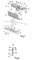
- Figure 1 shows a part of a door 2 of an electrical cabinet, in an inclined top view, and the main body 4 of a door handle 1 with the handle element 3 prior to assembly.
- the main body 4 has an essentially rectangular shape. It has a middle portion in the form of a plate, with a top side 27 and a bottom side 28. The bottom side 28 is the one which will be in planar contact with the front side of the door 2 when the handle 1 is fixed to the door 2.
- the middle portion of the main body 4 is provided at each of its short sides with a bar 14, projecting above the top side 27 of the middle plate, said bars forming the wall sections 14 of the main body 4. So looking at the main body 4 as one piece, the middle section forms a flat recess, bordered by the two bars or wall sections 14.
- each wall section 14 projects above the plate forming the middle section 42.
- the projecting sections 29 are provided at their bottom side, which is the side facing the door 2, with a unidirectional recess 13 each, being open towards the bottom side facing the door 2. Once the main body 4 is fixed to the door 2, the openings of these recesses 13 are closed by the door 2.
- FIG. 5a and 5b show the main body 4 in a detailed view, looking at the front side of the latch projection 10 in figure 5a , and looking at the backside, the side opposite to the latch projection, in figure 5b .
- latch plates 6a formed to the edge 38 of the middle portion 42 of the main body 4, one on the left side of the attachment part 7, one on the right side of the attachment part 7.
- the latch plates 6a are facing down from the middle portion plate 42 of the main body 4 in an approximately rectangular angle. Protruding out of the broad side of each latch plate 6a there are two latch noses 35 per latch plate 6a.
- the latch plates 6a are of a firm and solid consistence.
- each latch plate 6b there are two other latch plates 6b, formed to the edge 39 of the middle portion plate 42 of the main body 4, one to the left side and one to the right side of the attachment part 7.
- the other latch plates 6b are also facing down from the middle portion plate 42 of the main body 4 in an approximately rectangular angle. Protruding out of the broad side of each latch plate 6b there is one latch nose 36 per latch plate 6b.
- the other latch plates 6b are formed like a stretched U, being connected with two short legs 40 to the edge 39, so that a free spacing 37 is created between the middle portion plate 42 of the main body 4 and the long leg 41 of the other latch plate 6b.
- the latch nose 36 is formed to the long leg 41 of the other latch plate 6b.
- slot-like recesses 5 On the front side of the door, facing the bottom side of the main body 4 of the handle, there are slot-like recesses 5, arranged in two pairs of two, provided in an appropriate position corresponding to the position of the latch plates 6a, 6b when the main body 4 is inserted, so that the latch plates 6a and 6b of the main body 4 of the handle 1 will snap into these slot-like recesses 5.
- the slot-like recesses 5 function like an undercut.
- the latching noses 35, 36 are fixing the main body 4 to the door 2 by cooperating with the undercut formed by the slot-like recesses 5.
- the latch plates 6a on the front side of the middle portion 42 of the main body 4 are inflexible, firm and solid, whereas the other latch plates 6b on the side opposite the latch projection 10 are flexible and can be bent back and forth resiliently.
- the inflexible latch plates 6a with their latch noses 35 are snapped in, inserted into those two of slot-like recesses 5 which correspond to the position of these two inflexible latch plates 6a.
- the two flexible latch plates 6b with their latch noses 36 are snapped into those two of the slot-like recesses 5 corresponding to their position.
- the two inflexible latch plates 6a When opening the door, the largest force is applied to the two inflexible latch plates 6a, whereas the force applied to the inflexible latch plates 6b is minor. So the two latch plates 6a a firm and solid and have two latch noses 35 each to take up the force when opening.
- the other two latch plates 6b are flexible and have only one latch nose 36 each to make the final assembly of the main body to the door easy.
- an attachment part 7 in the form of a hollow cylinder.
- a hole 8 is provided giving access to the hollow center section of the hollow-cylinder-shaped attachment part 7.
- an additional hole 30 provided, which is meant to take up the hollow-cylinder-shaped attachment part 7 when the main body 4 of the handle 1 is assembled to the door 2.
- the hinge pins 15 are designed in such a way that they fit into the unidirectionally open recesses 13 in the projecting sections 29 of the wall sections 14.
- the arrow P indicates the sequence of assembly of the handle 1 to the door 2.
- the handle element 3 is held in such a position that the hinge pins 15 fit or snap into the recesses 13 in the projecting sections 29 of the wall sections 14 when the main body 4 is approached to the surface of the wall 2.
- the hinge pins are fixed between the recesses 13 and the surface of the wall 2, in such a way that the handle element 3 can be pivoted.
- the hollow-cylinder-shaped attachment part 7 is taken up in the hole 30.
- the handle 1 can very easily and in a robust manner be assembled upon fixing it to the door 2.
- a latch projection 10 facing outward, towards the narrow side 31 of the door 2.
- the latch projection 10 is wedge-shaped, with an upper wedge wall and a lower wedge wall.
- the attachment part 7 acts in conjunction with a springy holding part 11 see figure 3 and 4 , of the cabinet 20 or box to hold the door 2 in a closed position.
- a springy latch tongue 12 is provided at the wall of the hollow-cylinder-shaped attachment part 7 and the latch projection 10 is provided at one end of said springy latch tongue 12.
- the part which actually latches with the latch projection 10 is located at the free end of the springy holding part 11. It is a latching nose 32, protruding from the springy holding part 11. It is wedge-shaped as well, and its lower wedge wall is in snapping inter-action with the upper wedge wall of the latch projection 10 at the hollow-cylinder shaped attachment part 7.
- FIG. 3 one can see the cabinet 20 with the door 2 closed.
- the handle 1 is in the closed position as well.
- the handle element 3 is lying in the flat recess 16 (see fig. 1 ) of the main body 4, so that the surface of the handle element 3 is more or less flush with the top sides of the wall sections 14 of the main body 4.
- the latch projection 10 at the wall of the hollow-cylinder shaped attachment part 7 is in snapping interaction with the springy holding part 11 at the front wall of the electrical cabinet 20, as is described above.
- the springy holding part 11 is a section of a finger shaped bracket 21.
- the bracket 21 is shown as an isolated part in figure 2 .
- the finger-shaped bracket 21 is provided at the wall 22 of the cabinet 20 or box, whereby the free end 23 of the bracket 21 has the form of a latching tongue and forms a section acting as the springy holding part 11.
- the bracket 21 is provided with a fixing shaft 24, which is snapped into a locating opening 25 in the wall 22 of the cabinet 20 or box.
- the bracket 21 has further snapping noses 33 to fit into snapping recesses in the wall of the locating opening in the wall of the cabinet.
- the fixed retaining part 18 of the cabinet 20 is formed at the bracket 21 near the root 26 of the latching tongue.
- FIG 4 one can see the cabinet 20 with the door 2 closed.
- the handle element 3 is pivoted in the open position.
- a lock 9 is inserted into the inner part of the hollow-cylinder shaped attachment part 7.
- the lock is in its locked position.
- a licking bolt 17 is radially projecting above the shell of the hollow-cylinder-shaped attachment part 7. It cooperates with the fixed retaining part 18 of the bracket 21, so that the door 2 is locked.
- the bracket 21 has two functional portions for fulfilling two different functions.
- the first function is the releasable latching function in case there is either no lock inserted or the lock 9 is in its open position. This first function is fulfilled by the latching nose 32 at the springy holding part 11.
- the second function is the non-releasable holding function in case a lock 9 is inserted and the lock is in its locking position. This second function is achieved by the fixed retaining part 18.
- a handle 1 and an electrical cabinet 20 as described here are very easy and robust to assemble. They come as an assembly kit with few robust parts: cabinet 20, door 2, main body 4, handle element 3 and bracket 21, optionally as well a lock 9. Assembly can be made by the customer, by just click-fitting together the parts, no special skills or tools are needed, everything works just on a click-fit basis.
Priority Applications (2)
| Application Number | Priority Date | Filing Date | Title |
|---|---|---|---|
| EP14004066.8A EP2924203A1 (de) | 2014-03-27 | 2014-12-03 | Griff für eine Tür von einem Schaltschrank und Schaltschrank |
| RU2015111004A RU2015111004A (ru) | 2014-03-27 | 2015-03-26 | Ручка для двери шкафа для электрооборудования и шкаф для электрооборудования |
Applications Claiming Priority (2)
| Application Number | Priority Date | Filing Date | Title |
|---|---|---|---|
| EP14001130 | 2014-03-27 | ||
| EP14004066.8A EP2924203A1 (de) | 2014-03-27 | 2014-12-03 | Griff für eine Tür von einem Schaltschrank und Schaltschrank |
Publications (1)
| Publication Number | Publication Date |
|---|---|
| EP2924203A1 true EP2924203A1 (de) | 2015-09-30 |
Family
ID=50390978
Family Applications (1)
| Application Number | Title | Priority Date | Filing Date |
|---|---|---|---|
| EP14004066.8A Withdrawn EP2924203A1 (de) | 2014-03-27 | 2014-12-03 | Griff für eine Tür von einem Schaltschrank und Schaltschrank |
Country Status (2)
| Country | Link |
|---|---|
| EP (1) | EP2924203A1 (de) |
| RU (1) | RU2015111004A (de) |
Cited By (2)
| Publication number | Priority date | Publication date | Assignee | Title |
|---|---|---|---|---|
| CN112065171A (zh) * | 2019-06-11 | 2020-12-11 | 北京小米移动软件有限公司 | 智能门锁及门 |
| CN113530372A (zh) * | 2021-06-25 | 2021-10-22 | 南京钢铁股份有限公司 | 一种用电设备能量源挂牌上锁柜及其使用方法 |
Citations (5)
| Publication number | Priority date | Publication date | Assignee | Title |
|---|---|---|---|---|
| FR2716600A3 (fr) * | 1994-02-19 | 1995-08-25 | Hager Electro Gmbh | Poignée pour une porte ou un couvercle d'une armoire ou d'un coffret d'une installation électrique. |
| EP0845563A1 (de) * | 1996-11-27 | 1998-06-03 | Legrand | Griff für öffnungsfähigen Flügel, und Schrank wovon die Tür mit einem derartigen Griff ausgerüstet ist |
| DE29804457U1 (de) | 1997-03-26 | 1998-06-10 | Felten & Guilleaume Ag Oester | Griff für eine Tür oder einen Deckel von Schränken der Elektroinstallation |
| DE29906615U1 (de) * | 1999-04-14 | 1999-07-15 | Geyer Ag | Schließeinrichtung für elektrische Verteiler |
| EP1528190A1 (de) * | 2003-10-30 | 2005-05-04 | Ronis S.A. | Tür mit verriegelbarem an dieser Tür angepastem Handgriff |
-
2014
- 2014-12-03 EP EP14004066.8A patent/EP2924203A1/de not_active Withdrawn
-
2015
- 2015-03-26 RU RU2015111004A patent/RU2015111004A/ru not_active Application Discontinuation
Patent Citations (5)
| Publication number | Priority date | Publication date | Assignee | Title |
|---|---|---|---|---|
| FR2716600A3 (fr) * | 1994-02-19 | 1995-08-25 | Hager Electro Gmbh | Poignée pour une porte ou un couvercle d'une armoire ou d'un coffret d'une installation électrique. |
| EP0845563A1 (de) * | 1996-11-27 | 1998-06-03 | Legrand | Griff für öffnungsfähigen Flügel, und Schrank wovon die Tür mit einem derartigen Griff ausgerüstet ist |
| DE29804457U1 (de) | 1997-03-26 | 1998-06-10 | Felten & Guilleaume Ag Oester | Griff für eine Tür oder einen Deckel von Schränken der Elektroinstallation |
| DE29906615U1 (de) * | 1999-04-14 | 1999-07-15 | Geyer Ag | Schließeinrichtung für elektrische Verteiler |
| EP1528190A1 (de) * | 2003-10-30 | 2005-05-04 | Ronis S.A. | Tür mit verriegelbarem an dieser Tür angepastem Handgriff |
Cited By (3)
| Publication number | Priority date | Publication date | Assignee | Title |
|---|---|---|---|---|
| CN112065171A (zh) * | 2019-06-11 | 2020-12-11 | 北京小米移动软件有限公司 | 智能门锁及门 |
| CN112065171B (zh) * | 2019-06-11 | 2022-04-01 | 北京小米移动软件有限公司 | 智能门锁及门 |
| CN113530372A (zh) * | 2021-06-25 | 2021-10-22 | 南京钢铁股份有限公司 | 一种用电设备能量源挂牌上锁柜及其使用方法 |
Also Published As
| Publication number | Publication date |
|---|---|
| RU2015111004A (ru) | 2016-10-20 |
Similar Documents
| Publication | Publication Date | Title |
|---|---|---|
| US7185864B2 (en) | Door hook with hinge | |
| EP3322269A1 (de) | Klammervorrichtung und gleitschienenanordnung damit | |
| US9617754B2 (en) | Clip fixing element for the assembly of fixture devices such as locks, hinge parts and handles in openings in a thin wall | |
| KR101499098B1 (ko) | 손 끼임 방지기능을 가지는 문짝 | |
| US20100189492A1 (en) | Quick Assembly Desk System And Components Therefor | |
| EP2924203A1 (de) | Griff für eine Tür von einem Schaltschrank und Schaltschrank | |
| CN110915082A (zh) | 带有扣关门的竖直线缆管理器 | |
| WO2014023235A1 (zh) | 铰链固定结构和隐藏式铰链及容器 | |
| JP5187970B2 (ja) | 電気機器収納用箱体 | |
| KR20130054268A (ko) | 공기 안내 시스템 | |
| US7549713B2 (en) | Refrigerator handle mounting arrangement | |
| US20080238110A1 (en) | Case latch assembly | |
| US20070247035A1 (en) | Computer enclosure with removable side panel | |
| US20090303666A1 (en) | Thermoplastic electrical enclosure | |
| US20160115717A1 (en) | Door latch | |
| KR101954898B1 (ko) | 가구용 상부경첩 | |
| KR200467183Y1 (ko) | 벽 스위치의 브라켓 | |
| KR20070077665A (ko) | 클립 체결 구조 | |
| JP5975858B2 (ja) | 天井点検口 | |
| US20190287432A1 (en) | Display sign | |
| EP3584392A1 (de) | Türschlagbolzen zur verhinderung von türbewegungen | |
| JP5441048B2 (ja) | 隙間閉塞部材の取付構造 | |
| JP6386617B2 (ja) | トイレブースのパネル体取り付け構造 | |
| KR200446952Y1 (ko) | 도어용 손잡이 | |
| KR20090050150A (ko) | 목재 사물함용 도어의 연결구조 |
Legal Events
| Date | Code | Title | Description |
|---|---|---|---|
| PUAI | Public reference made under article 153(3) epc to a published international application that has entered the european phase |
Free format text: ORIGINAL CODE: 0009012 |
|
| AK | Designated contracting states |
Kind code of ref document: A1 Designated state(s): AL AT BE BG CH CY CZ DE DK EE ES FI FR GB GR HR HU IE IS IT LI LT LU LV MC MK MT NL NO PL PT RO RS SE SI SK SM TR |
|
| AX | Request for extension of the european patent |
Extension state: BA ME |
|
| STAA | Information on the status of an ep patent application or granted ep patent |
Free format text: STATUS: THE APPLICATION IS DEEMED TO BE WITHDRAWN |
|
| 18D | Application deemed to be withdrawn |
Effective date: 20160331 |