EP2923947B1 - Systeme und verfahren zur regelung einer flugzeugkraftstofftankumgebung - Google Patents
Systeme und verfahren zur regelung einer flugzeugkraftstofftankumgebung Download PDFInfo
- Publication number
- EP2923947B1 EP2923947B1 EP15154609.0A EP15154609A EP2923947B1 EP 2923947 B1 EP2923947 B1 EP 2923947B1 EP 15154609 A EP15154609 A EP 15154609A EP 2923947 B1 EP2923947 B1 EP 2923947B1
- Authority
- EP
- European Patent Office
- Prior art keywords
- fuel tank
- temperature
- air
- flow
- processor
- Prior art date
- Legal status (The legal status is an assumption and is not a legal conclusion. Google has not performed a legal analysis and makes no representation as to the accuracy of the status listed.)
- Active
Links
Images



Classifications
-
- B—PERFORMING OPERATIONS; TRANSPORTING
- B65—CONVEYING; PACKING; STORING; HANDLING THIN OR FILAMENTARY MATERIAL
- B65D—CONTAINERS FOR STORAGE OR TRANSPORT OF ARTICLES OR MATERIALS, e.g. BAGS, BARRELS, BOTTLES, BOXES, CANS, CARTONS, CRATES, DRUMS, JARS, TANKS, HOPPERS, FORWARDING CONTAINERS; ACCESSORIES, CLOSURES, OR FITTINGS THEREFOR; PACKAGING ELEMENTS; PACKAGES
- B65D90/00—Component parts, details or accessories for large containers
- B65D90/22—Safety features
- B65D90/32—Arrangements for preventing, or minimising the effect of, excessive or insufficient pressure
- B65D90/34—Venting means
-
- B—PERFORMING OPERATIONS; TRANSPORTING
- B64—AIRCRAFT; AVIATION; COSMONAUTICS
- B64D—EQUIPMENT FOR FITTING IN OR TO AIRCRAFT; FLIGHT SUITS; PARACHUTES; ARRANGEMENT OR MOUNTING OF POWER PLANTS OR PROPULSION TRANSMISSIONS IN AIRCRAFT
- B64D37/00—Arrangements in connection with fuel supply for power plant
- B64D37/005—Accessories not provided for in the groups B64D37/02 - B64D37/28
-
- B—PERFORMING OPERATIONS; TRANSPORTING
- B64—AIRCRAFT; AVIATION; COSMONAUTICS
- B64F—GROUND OR AIRCRAFT-CARRIER-DECK INSTALLATIONS SPECIALLY ADAPTED FOR USE IN CONNECTION WITH AIRCRAFT; DESIGNING, MANUFACTURING, ASSEMBLING, CLEANING, MAINTAINING OR REPAIRING AIRCRAFT, NOT OTHERWISE PROVIDED FOR; HANDLING, TRANSPORTING, TESTING OR INSPECTING AIRCRAFT COMPONENTS, NOT OTHERWISE PROVIDED FOR
- B64F5/00—Designing, manufacturing, assembling, cleaning, maintaining or repairing aircraft, not otherwise provided for; Handling, transporting, testing or inspecting aircraft components, not otherwise provided for
- B64F5/40—Maintaining or repairing aircraft
- B64F5/45—Repairing leakages in fuel tanks
-
- B—PERFORMING OPERATIONS; TRANSPORTING
- B64—AIRCRAFT; AVIATION; COSMONAUTICS
- B64F—GROUND OR AIRCRAFT-CARRIER-DECK INSTALLATIONS SPECIALLY ADAPTED FOR USE IN CONNECTION WITH AIRCRAFT; DESIGNING, MANUFACTURING, ASSEMBLING, CLEANING, MAINTAINING OR REPAIRING AIRCRAFT, NOT OTHERWISE PROVIDED FOR; HANDLING, TRANSPORTING, TESTING OR INSPECTING AIRCRAFT COMPONENTS, NOT OTHERWISE PROVIDED FOR
- B64F5/00—Designing, manufacturing, assembling, cleaning, maintaining or repairing aircraft, not otherwise provided for; Handling, transporting, testing or inspecting aircraft components, not otherwise provided for
- B64F5/60—Testing or inspecting aircraft components or systems
Definitions
- the subject matter described herein generally relates to controlling an environment of a fuel tank and, more particularly, to systems and methods for curing a sealant within a fuel tank of an aircraft.
- a sealant is applied within an interior of the fuel tank to seal the fuel tank and keep it from leaking. After a sealant is applied, the sealant must be cured before the assembly of the fuel tank is complete.
- Two of the main factors that affect the curing process are temperature and relative humidity (RH) within the fuel tank.
- RH relative humidity
- curing times of a sealant may vary based on time of year and/or factory environment. For example, during summer, a sealant may take up to 10% longer than normal to cure due to low RH and uneven air distribution. During winter, a sealant may take up to twice as long to cure due to low temperatures, low RH, and uneven air distribution.
- the sealant is curing within the fuel tank
- mechanics may be required to work for extended periods of time inside the fuel tank.
- the environment of the fuel tank must be monitored such that the temperature and/or RH are maintained at acceptable levels. For example, if the temperature within the fuel tank exceeds 26° C (79° F), the mechanics are required to exit the fuel tank for safety purposes.
- the sealant may cure more quickly as the temperature increases, the mechanics are unable to continue working in an environment that is above 26° C (79° F).
- IPA isopropanol
- MPK methyl propyl ketone
- current systems and methods of ventilating a fuel tank create large variances in temperature, RH levels, and air circulation throughout the fuel tank.
- curing times of a sealant are non-uniform throughout the fuel tank and dead spots created by poor circulation enable a pooling effect of volatile organic compounds (VOCs). This not only creates discomfort for the mechanics working within the fuel tank, but can lead to such a dangerous environment that prohibits the mechanics to work within the fuel tank.
- US2011/0316299 discloses a transportable system for maintenance and repair of fuel tanks, such as aircraft fuel tanks.
- the system includes means to vent the tanks with air.
- a system for controlling an environment within an aircraft fuel tank according to clam 1 is provided.
- a method for controlling an environment within an aircraft fuel tank includes receiving a current measure of a temperature and/or a relative humidity within the fuel tank, and increasing or decreasing one or more of a temperature of a flow of air and a humidity within the flow of air directed through a plurality of vents along a conduit that defines a path through the fuel tank.
- one or more non-transitory computer readable media comprising instructions for controlling an environment within a fuel tank.
- the instructions cause a processor to perform the steps of receiving a current measure of a temperature and/or a relative humidity within the fuel tank, and increasing or decreasing one or more of a temperature of a flow of air and a humidity within the flow of air directed through a plurality of vents along a conduit that defines a path through the fuel tank.
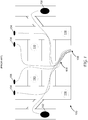
- current systems and methods for venting a fuel tank 100 utilize two 10" ducts 102 located in an outboard section of fuel tank 100 and four 4" ducts 104 located in a forward section of fuel tank 100. This enables "new air” to be blown into fuel tank 100 while “old air” is being pushed out of ducts 102 and 104.
- a sealant (not shown) is applied within an interior of fuel tank 100 in order to keep fuel tank 100 from leaking.
- the temperature and relative humidity (RH) within fuel tank 100 must be controlled.
- a sealant such as an A2 type sealant or a B2 type sealant require an environment of 25.0° C (77°F) and 50% RH to enable curing within 72 hours and 24 hours, respectively.
- high velocities e.g., 1524 m/s (5,000 fps)
- hot spots e.g., 29.4° C (85°F) at 108 in Figure 1
- cold spots e.g., 18.3° C (65°F) at 110 in Figure 1
- VOCs volatile organic compounds
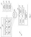
- FIG. 2 a block diagram illustrating an exemplary system 200 for use in controlling an environment of a fuel tank 202 in accordance with the embodiments of the present disclosure will now be described. While system 200 is described herein as being associated with fuel tank 202 of an aircraft, system 200 is applicable with numerous other environments and/or configurations, such as a sewage management system and fuel tanks of marine vessels.
- System 200 includes a computing device (e.g., controller) 204, a processor 206 for executing instructions, and a memory device 208.
- Computing device 204 may operate in a networked environment using logical connections to one or more remote computers. Although described in connection with an exemplary computing system environment, embodiments of the present disclosure are operational with numerous other general purpose or special purpose computing system environments or configurations.
- Examples of well-known computing systems, environments, and/or configurations that may be suitable for use with aspects of the present disclosure include, but are not limited to, personal computers, server computers, hand-held or laptop devices, multiprocessor systems, microprocessor-based systems, programmable consumer electronics, mobile telephones, network PCs, minicomputers, mainframe computers, distributed computing environments that include any of the above systems or devices, and the like.
- Processor 206 may include a processing unit, such as, without limitation, an integrated circuit (IC), an application specific integrated circuit (ASIC), a microcomputer, a programmable logic controller (PLC), and/or any other programmable circuit.
- Processor 206 may include multiple processing units (e.g., in a multi-core configuration).
- Computing device 204 is configurable to perform the operations/processes (e.g., process 300 described below) described herein by programming processor 206 with appropriate instructions.
- processor 206 may be programmed by encoding an operation as one or more executable instructions and providing the executable instructions to processor 206 in memory device 208 that is coupled to processor 206.
- executable instructions are stored in memory device 208.
- Memory device 208 is any device allowing information, such as executable instructions and/or other data, to be stored and retrieved.
- memory device 208 may store computer readable instructions for determining one or more of the following: temperature levels, humidity levels, and a level of velocity for a flow of air.
- memory device 208 may be configured to store historic fuel tank environment data, such as temperature and RH data from defined locations within a plurality of fuel tanks and/or any other data suitable for use with the methods described herein.
- processor 206 and memory device 208 may be remote from computing device 204.
- the data and the computer-executable instructions may be stored in a cloud service, a database, or other memory area accessible by computing device 204. Such embodiments reduce the computational and storage burden on computing device 204.
- computing device 204 includes at least one presentation device 210 for presenting information to a user.
- Presentation device 210 is any component capable of conveying information to a user.
- Presentation device 210 may include, without limitation, a display device (e.g., a liquid crystal display (LCD), organic light emitting diode (OLED) display, or "electronic ink" display) and/or an audio output device (e.g., a speaker or headphones).
- presentation device 210 includes an output adapter, such as a video adapter and/or an audio adapter.
- An output adapter is operatively coupled to processor 206 and configured to be operatively coupled to an output device, such as a display device or an audio output device.
- computing device 204 includes an input device 212 for receiving input from a user.
- Input device 212 may include, for example, a keyboard, a pointing device, a mouse, a stylus, a touch sensitive panel (e.g., a touch pad or a touch screen), a position detector, and/or an audio input device.
- a single component, such as a touch screen, may function as both an output device of presentation device 210 and input device 212.
- Computing device 204 also includes a communication interface 214, which is configured to be communicatively coupled to sensors 216 and airflow system 218 via, for example, network 220.
- Network 220 may include, without limitation, the Internet, a local area network (LAN), a wide area network (WAN), a wireless LAN (WLAN), a mesh network, and/or a virtual private network (VPN).
- LAN local area network
- WAN wide area network
- WLAN wireless LAN
- mesh network and/or a virtual private network (VPN).
- VPN
- Sensors 216 provide computing device 204 with readings of one or more of the following: temperature, RH, and wind/air velocities within fuel tank 202 throughout fuel tank 202. Sensors 216 may provide these readings/information in real time, periodically (e.g., every minute, every five minutes, or every hour), or upon request.
- a computing device 204 utilizes the information received from sensors 202 to adjust a temperature level of an airflow, a humidity level of the airflow, an amount of air in the airflow, and a velocity of the airflow provided by a conduit 222 coupled to airflow system 216.
- computing device 204 may adjust an amount/velocity of the airflow, a temperature of the airflow, or a humidity level of the airflow based on an identified time (e.g., a desired time) to cure a sealant and/or a rate at which air within fuel tank 202 is being pulled out of fuel tank 202 through one or more vents on an exterior wall of the fuel tank.
- a plurality of conduits 222 are provided within fuel tank 202. More specifically, a manifold (not shown) may connect a plurality of conduits 222 such that each bay/portion of fuel tank 202 may have a separate conduit 222.
- conduit 222 is made from, for example, plastic, rubber, or other flexible type of tubing material that may prevent chafing and/or increase portability.
- Conduit 222 includes a plurality of micro vents 230 that enable the airflow to be directed into fuel tank 202 by a path created by conduit 222.
- micro vents 230 are made from, for example, plastic.
- micro vents 230 may have the ability to adjust for calibration or fine tuning of system 200.
- sensors 202 may be placed on an exterior or an interior of micro vents 230 to measure the temperature, the RH, and/or velocity of the airflow as it exits micro vents 230 or air ducts located on an exterior wall of fuel tank 202.
- airflow system 218 includes an airflow component 224, a temperature component 226, and/or humidity component 228.
- airflow component includes a combination of air handlers and blowers to create defined amounts of air/velocity as needed.
- temperature component such as a thermocouple
- humidity component 228 provides water/moister to the airflow such that a defined RH level can be achieved within the airflow and therefore within fuel tank 202.
- a method for curing a sealant within a fuel tank 400 of an aircraft is provided. While method is described herein as being performed within fuel tank 400 of an aircraft, method is applicable with numerous other environments and/or configurations, such as a sewage management system and fuel tanks of marine vessels.
- Method begins at 302 whereby computing device 402 receives, from at least one sensor 404 configured to measure temperature and relative humidity within fuel tank 400, a current measure of a temperature and/or a RH within fuel tank 400.
- each sensor 404 can measure both temperature and RH, or in another embodiment, a first sensor 404 measures temperature and a second sensor 404 measures RH.
- each sensor 404 may be placed throughout an interior of fuel tank 400 in order to measure temperature and RH at defined locations within fuel tank 400.
- computing device 402 identifies a time to cure a sealant within fuel tank 400. For example, a user may select a time allotted in an assembly of fuel tank 400 for curing the sealant.
- a user may provide computing device 402 with a time for curing and as a result, computing device 402 establishes an environment (e.g., a temperature and RH) needed to achieve curing during the selected time.
- an environment e.g., a temperature and RH
- the temperature and RH levels may be provided to computing device 402.
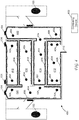
- computing device 402 increases or decreases one or more of a temperature of an airflow and a humidity level within the airflow that is directed through a plurality of vents 408 along a conduit 410 that defines a path through fuel tank 400. For example, as temperature readings are provided by sensor 402, computing device 402 may increase a temperature of the airflow if a temperature within fuel tank 400 is below a temperature threshold level, or computing device 402 may decrease a temperature of the airflow if a temperature within fuel tank 400 is above a temperature threshold level.
- computing device 402 may increase a moisture level within the airflow if a RH level within fuel tank 400 is below a RH threshold level, or computing device 402 may decrease a moister level of the airflow if a RH level within fuel tank 400 is above a RH threshold level.
- a current level of VOCs within fuel tank 400 is also received by computing device 402 from sensor 402.
- computing device 402 may increase a velocity of the airflow when the current level of the VOCs exceeds a VOC threshold level in a particular area of fuel tank 400. By increasing the velocity of the airflow, VOCs can be purged from the system or reduced below the VOC threshold level.
- the VOC threshold level is based on a chemical being measured. Further, the VOC may be a percentage (e.g., 10%) of an exposure limit of a particular chemical set by, for example, the Occupational Health and Safety Administration (OSHA). In another embodiment, the VOC threshold is about 20 ppm.
- computing device 402 may trigger an alarm that provides a notification that a level of VOCs within fuel tank 400 has exceeded the VOC threshold level, which notifies a user that the environment within fuel tank 400 is unsafe.
- computing device 402 identifies a number of humans (e.g., mechanics) within fuel tank 400 in order to create a safe/suitable environment for the mechanics working therein. For example, since chemicals such as isopropanol (IPA) and methyl propyl ketone (MPK) are used during the assembly, enabling mechanics to continue work within fuel tank 400 involves heavily ventilating fuel tank 400 in order to create an environment that is safe/suitable for the mechanics. Further, to lower a tact time for curing a sealant, a temperature and/or RH within fuel tank 400 may be increased.
- IPA isopropanol
- MPK methyl propyl ketone
- vents 400 may be strategically placed such that the airflow is blowing on each mechanic, which lowers a perceived temperature and allows for elevated baseline temperatures that aid in the curing process.
- computing device 402 increases a velocity of the airflow and/or decreases a temperature of the airflow based on a number of humans/mechanics that are or will be within fuel tank 400 to enable a perceived temperature or an actual temperature within fuel tank 400 to be at or below a safe temperature threshold level, for example, at or below 26.1° C (79°F).
- computing device 402 takes into consideration body heat given off by each of the mechanics within fuel tank 400. As such, a temperature and RH within fuel tank 400 is dynamically adjusted in real time in order to account for the excess heat from, for example, body heat, based on a number of mechanics within fuel tank 400.
- computing device 402 may increase a temperature within fuel tank 400 to a maximum temperature threshold (e.g., a temperature that optimizes curing, such as from about 60° C (140°F) to about 121.1° C (250°F)) and increase an RH within fuel tank 400 to a maximum RH threshold (e.g., a RH that optimizes curing, such as from about 70% RH to about 90% RH).
- a maximum temperature threshold e.g., a temperature that optimizes curing, such as from about 60° C (140°F) to about 121.1° C (250°F)
- an RH within fuel tank 400 e.g., a RH that optimizes curing, such as from about 70% RH to about 90% RH.
- a curing process of a sealant can be cut at least in half, for example, from 72 hours to 36 hours.
- fuel tank 400 includes a plurality of bays, for example, bay 412, bay 414, bay 416, bay 418, bay 420, and bay 422.
- each bay may be considered to have its own environment separate from other bays.
- access to each bay may be sealed off from other bays during the assembly process using, for example, bulkhead covers.
- computing device 402 may increase a temperature within bay 418 to a maximum temperature threshold and increase an RH within bay 418 to a maximum RH threshold, while maintaining an environment within bays 412, 414, 416, 420, and 422 at safe/comfortable level for a mechanic to work therein.
- historic data may be accessed, analyzed, and/or provided to a virtual simulation that emulates method 300 being applied within fuel tank 400.
- Historic fuel tank environment data includes historic temperature levels, historic RH levels, historic VOC levels, and historic airflow velocity levels at defined locations within a plurality of fuel tanks. The collection of this data along with the virtual simulation provides an ability to optimize a placement of conduit 410 and vents 408 throughout fuel tank 400 as areas of most concern or that have been problematic in the past may be addressed by the dynamic placement of conduit 410. Further, a temperature level of the airflow, an RH level of the airflow, and/or a velocity level of the airflow may also be optimized based on the historic data/virtual simulation.
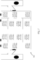
- FIG. 5 actual data (temperature, RH, and air velocity) acquired from a BMS5-45 fuel tank (fuel tank 500) using conventional systems/methods is provided (see, for example, the system shown in Figure 1 ).
- the air entering fuel tank 500 adjacent to vent 502 is 19.4° C (67°F), has an RH of 71% and has a velocity of 1829 m/s (6K fps);
- the air entering fuel tank 500 adjacent to vent 504 is 20.0° C (68°F), has an RH of 67% and has a velocity of 914 m/s (3K fps);
- the air entering fuel tank 500 adjacent to vent 506 is 21.1° C (70°F), has an RH of 70% and has a velocity of 1067 m/s (3.5K fps);
- the air entering fuel tank 500 adjacent to vent 508 is 20.0° C (68°F), has an RH of 70% and has a velocity of 1067 m/s (3.5K fps);
- Figure 5 also provides environmental data that was acquired at other locations throughout fuel tank 500.
- the temperature, RH, and velocity of the air flowing through fuel tank 500 is very inconsistent, with temperatures ranging from 19.4° C (67°F) to 22.8° C (73°F), RH levels ranging from 61% RH to 71% RH, and air velocity ranging from 2438 m/s (8fps) to 1829 m/s (6K fps).
- Figure 6 provides actual cure times of a Class A2 sealant and a Class B2 sealant applied within fuel tank 500 under the conditions provided in Figure 5 .
- a Class A2 sealant is expected to cure within 72 hours if the environment is at 25.0° C (77°F) with 50% RH.
- a Class B2 sealant is expected to cure within 24 hours if the environment is at 25.0° C (77°F) with 50% RH.
- the amount of time it takes the Class A2 sealant and the Class B2 sealant to cure varies by 12 hours, respectively, throughout fuel tank 500.
- cure times of the Class A2 sealant and the Class B2 sealant utilizing embodiments of the present disclosure, for example, the system shown in Figure 4 are provided.
- the cure times shown in Figure 7 are based on an airflow temperature of 60.0° C (140°F) with 60% RH provided throughout fuel tank 500 using a plurality of conduits (e.g., conduit 410) and vents 408, shown in Figure 4 .
- the cure times for the Class A2 sealant and the Class B2 sealant are consistent throughout fuel tank 500 (e.g., 36 hours for Class A2 sealant and 12 hours for Class B2 sealant).
- Figure 7 also illustrates the change/delta of time for curing the Class A2 sealant and the Class B2 sealant at various locations throughout fuel tank 500 when compared to the cure times shown in Figure 6 using conventional systems/methods.
- the cure times for the Class A2 sealant and the Class B2 sealant have been reduced by 50% to almost 60% utilizing the systems and methods of the present disclosure, when compared to the cure times of the Class A2 sealant and the Class B2 sealant utilizing conventional systems and methods, for example, shown in Figures 1 , 5 , and 6 .
Landscapes
- Engineering & Computer Science (AREA)
- Aviation & Aerospace Engineering (AREA)
- Manufacturing & Machinery (AREA)
- Transportation (AREA)
- Mechanical Engineering (AREA)
- Fuel Cell (AREA)
- Filling Or Discharging Of Gas Storage Vessels (AREA)
- Cooling, Air Intake And Gas Exhaust, And Fuel Tank Arrangements In Propulsion Units (AREA)
Claims (14)
- System zum Steuern einer Umgebung in einem Kraftstofftank (202), wobei das System aufweist:eine Leitung (222), die eine Mehrzahl von Lüftungen (408) aufweist, wobei die Leitung (222) einen Weg durch den Kraftstofftank (202) definiert, wobei die Leitung (222) konfiguriert ist, um einen Luftfluss entlang dem Weg und aus der Mehrzahl von Lüftungen (408) zu richten;dadurch gekennzeichnet, dass es ferner aufweist:zumindest einen Sensor (216), der konfiguriert ist, um zumindest eine von Temperatur und relativer Feuchtigkeit in dem Kraftstofftank (202) zu messen; undeine Steuereinrichtung (204), die einen Prozessor (206) aufweist, wobei der Prozessor (206) programmiert ist, um von dem zumindest einen Sensor (216) ein gegenwärtiges Maß der Temperatur und/oder der relativen Feuchtigkeit innerhalb des Kraftstofftanks (202) zu empfangen.
- Das System von Anspruch 1, wobei der Prozessor (206) ferner programmiert ist um:Identifizieren einer Zeit zum Aushärten eines Dichtmittels innerhalb des Kraftstofftanks (202); undbasierend auf der identifizierten Zeit, Erhöhen oder Verringern von einer oder mehrerer der Folgenden:einer Temperatur des Luftflusses und einer Feuchtigkeit innerhalb des Luftflusses.
- Das System von Anspruch 1 oder 2, wobei der zumindest eine Sensor (216) ferner konfiguriert ist, um einen Pegel von flüchtigen organischen Verbindungen innerhalb des Kraftstofftanks (202) zu messen, und wobei der Prozessor (206) ferner programmiert ist, um eine Geschwindigkeit des Luftflusses zu erhöhen, wenn der Pegel der flüchtigen organischen Verbindungen einen Schwellenwertpegel überschreitet.
- Das System von einem der Ansprüche 1 bis 3, wobei der Prozessor (206) ferner programmiert ist, um eine Geschwindigkeit des Luftflusses basierend auf der identifizierten Zeit und/oder einer Rate einzustellen, mit der Luft in dem Kraftstofftank (202) durch eine oder mehrere Lüftungen an einer Außenwand des Kraftstofftanks (202) aus dem Kraftstofftank (202) gesaugt wird.
- Das System von einem der Ansprüche 1 bis 4, wobei der Prozessor (206) ferner programmiert ist zum:Identifizieren einer Anzahl von Menschen innerhalb des Kraftstofftanks (202); undErhöhen einer Geschwindigkeit des Luftflusses und/oder Verringern der Temperatur des Luftflusses basierend auf der Anzahl von Menschen innerhalb des Kraftstofftanks (202), um zu ermöglichen, dass die Temperatur bei oder unter einem sicheren Temperaturschwellenwert liegt.
- Das System von einem der Ansprüche 1 bis 5, wobei der Prozessor (206) ferner programmiert ist zum:Bestimmen, dass sich in dem Kraftstofftank (202) kein Mensch befindet;Erhöhen der Temperatur in dem Kraftstofftank (202) auf einen maximalen Temperaturschwellenwert; undErhöhen der relativen Feuchtigkeit innerhalb des Kraftstofftanks (202) auf einen maximalen Schwellenwert der relativen Feuchtigkeit.
- Das System von einem der Ansprüche 1 bis 6, wobei der Prozessor (206) ferner programmiert ist, zum:Empfangen von historischen Kraftstofftankumgebungsdaten, wobei die historischen Kraftstofftankumgebungsdaten Temperatur und relative Feuchtigkeitsdaten von definierten Orten innerhalb einer Mehrzahl von Kraftstofftanks aufweisen; undDefinieren des Wegs der Leitung (222) basierend auf den historischen Kraftstofftankumgebungsdaten.
- Das System von Anspruch 7, wobei der Prozessor (206) ferner programmiert ist, um basierend auf den historischen Kraftstofftankumgebungsdaten und einem Ort von Dichtmittel innerhalb des Kraftstofftanks (202) für jede der Mehrzahl von Lüftungen (408) Positionen entlang der Leitung (222) zu bestimmen.
- Verfahren zum Steuern einer Umgebung in einem Kraftstofftank (202), wobei das Verfahren aufweist:Empfangen des gegenwärtigen Maßes einer Temperatur und/oder einer relativen Feuchtigkeit innerhalb des Kraftstofftanks (202); undErhöhen oder Verringern von einer oder mehreren einer Temperatur eines Luftflusses und einer Feuchtigkeit innerhalb des Luftflusses, der durch eine Mehrzahl von Lüftungen (408) entlang einer Leitung (222), die einen Weg durch den Kraftstofftank (202) definiert, gerichtet ist.
- Das Verfahren von Anspruch 9, das ferner aufweist:Identifizieren einer Zeit zum Aushärten von Dichtmittel innerhalb des Kraftstofftanks (202); undbasierend auf der identifizierten Zeit, Erhöhen oder Verringern einer oder mehrerer einer Temperatur eines Luftflusses und einer Feuchtigkeit innerhalb des Luftflusses, der durch eine Mehrzahl von Lüftungen (408) entlang einer Leitung (222), die einen Weg durch den Kraftstofftank (202) definiert, gerichtet ist.
- Das Verfahren von Anspruch 10, das ferner aufweist, eine Geschwindigkeit des Luftflusses basierend auf der identifizierten Zeit und/oder einer Rate einzustellen, mit der Luft in dem Kraftstofftank (202) durch eine oder mehrere Lüftungen an einer Außenwand des Kraftstofftanks aus dem Kraftstofftank ausgesaugt wird.
- Das Verfahren von Anspruch 9, das ferner aufweist:Empfangen, von zumindest einem Sensor (216), eines gegenwärtigen Pegels von flüchtigen organischen Verbindungen innerhalb des Kraftstofftanks (202); undErhöhen einer Geschwindigkeit des Luftflusses, wenn der gegenwärtige Pegel der flüchtigen organischen Verbindungen einen Schwellenwertpegel überschreitet.
- Das Verfahren von Anspruch 9, das ferner aufweist:Identifizieren einer Anzahl von Menschen innerhalb des Kraftstofftanks (202); undErhöhen einer Geschwindigkeit des Luftflusses und/oder Verringern der Temperatur des Luftflusses basierend auf der Anzahl von Menschen innerhalb des Kraftstofftanks (202), um zu ermöglichen, dass die Temperatur bei oder unter einem sicheren Temperaturschwellenwert liegt.
- Das Verfahren von Anspruch 9, das ferner aufweist:Empfangen von historischen Kraftstofftankumgebungsdaten, wobei die historischen Kraftstofftankumgebungsdaten Temperatur und relative Feuchtigkeitsdaten von definierten Orten innerhalb einer Mehrzahl von Kraftstofftanks aufweisen; undDefinieren des Wegs der Leitung (222) basierend auf den historischen Kraftstofftankumgebungsdaten.
Applications Claiming Priority (1)
| Application Number | Priority Date | Filing Date | Title |
|---|---|---|---|
| US14/223,749 US9969549B2 (en) | 2014-03-24 | 2014-03-24 | Systems and methods for controlling a fuel tank environment |
Publications (3)
| Publication Number | Publication Date |
|---|---|
| EP2923947A2 EP2923947A2 (de) | 2015-09-30 |
| EP2923947A3 EP2923947A3 (de) | 2015-10-07 |
| EP2923947B1 true EP2923947B1 (de) | 2017-04-05 |
Family
ID=52577620
Family Applications (1)
| Application Number | Title | Priority Date | Filing Date |
|---|---|---|---|
| EP15154609.0A Active EP2923947B1 (de) | 2014-03-24 | 2015-02-11 | Systeme und verfahren zur regelung einer flugzeugkraftstofftankumgebung |
Country Status (5)
| Country | Link |
|---|---|
| US (2) | US9969549B2 (de) |
| EP (1) | EP2923947B1 (de) |
| JP (1) | JP6687325B2 (de) |
| CN (1) | CN104943870B (de) |
| CA (1) | CA2882473C (de) |
Families Citing this family (2)
| Publication number | Priority date | Publication date | Assignee | Title |
|---|---|---|---|---|
| US9969549B2 (en) * | 2014-03-24 | 2018-05-15 | The Boeing Company | Systems and methods for controlling a fuel tank environment |
| CN107618677B (zh) * | 2017-09-11 | 2020-03-03 | 中国航空工业集团公司西安飞机设计研究所 | 一种飞机燃油测量试验系统 |
Family Cites Families (21)
| Publication number | Priority date | Publication date | Assignee | Title |
|---|---|---|---|---|
| JPS5517017A (en) | 1978-07-20 | 1980-02-06 | Tokyo Shibaura Electric Co | Air balancing apparatus |
| JPS57202462A (en) | 1981-06-05 | 1982-12-11 | Mitsubishi Electric Corp | Air conditioner |
| GB8703247D0 (en) * | 1987-02-12 | 1987-03-18 | British Aerospace | Disposal of water in aircraft fuel tanks |
| JPH06344366A (ja) * | 1993-06-10 | 1994-12-20 | Mitsubishi Heavy Ind Ltd | 樹脂硬化監視方法及びその装置 |
| FR2728331A1 (fr) * | 1994-12-15 | 1996-06-21 | Cerga | Procede et dispositif de modulation de la ventilation de locaux |
| JP2000343609A (ja) * | 1999-06-03 | 2000-12-12 | Shonan Gosei Jushi Seisakusho:Kk | 管ライニング工法 |
| FR2827530B1 (fr) * | 2001-07-17 | 2004-05-21 | Commissariat Energie Atomique | Procede de traitement d'une surface par un gel de traitement, et gel de traitement |
| WO2005123145A2 (en) * | 2004-01-16 | 2005-12-29 | The Government Of The United States Of America As Represented By The Secretary Of The Department Of Health And Human Services | Method and apparatus for bioweapon decontamination |
| US7776292B2 (en) * | 2004-01-16 | 2010-08-17 | Cdic, Inc. | Method and apparatus for bioweapon decontamination |
| US7204868B2 (en) * | 2004-03-30 | 2007-04-17 | The Boeing Company | Method and apparatus for generating an inert gas on a vehicle |
| US20080317647A1 (en) * | 2004-05-28 | 2008-12-25 | Tari Taricco | Autoclaves with Combined Air Flow |
| US20160281348A9 (en) * | 2005-05-06 | 2016-09-29 | Best Technologies, Inc. | Modular building utilities systems and methods |
| JP4618099B2 (ja) * | 2005-11-04 | 2011-01-26 | パナソニック株式会社 | 換気装置 |
| US20100163634A1 (en) * | 2006-05-18 | 2010-07-01 | Klein Michael J | Systems and methods for monitoring, controlling and limiting usage of utilities |
| JP2007326048A (ja) * | 2006-06-08 | 2007-12-20 | Bridgestone Corp | オートクレーブの減圧方法およびオートクレーブ |
| US7877233B2 (en) * | 2006-07-26 | 2011-01-25 | Invensys Systems, Inc. | Selectively presenting timestamped time-series data values for retrieved supervisory control and manufacturing/production parameters |
| US20110029413A1 (en) * | 2008-01-31 | 2011-02-03 | Israel Ben-Tzur | Perishable lifetime management system and method |
| WO2010039313A2 (en) * | 2008-06-27 | 2010-04-08 | Klein Michael J | Systems and methods for monitoring, controlling and limiting usage of utilities |
| WO2010081196A1 (en) * | 2009-01-16 | 2010-07-22 | Neil Mccoubrey | Multi functional transportable field maintenance and repair assembly |
| US9221547B2 (en) * | 2010-06-25 | 2015-12-29 | The Boeing Company | Static dissipative fuel tank coatings and methods |
| US9969549B2 (en) * | 2014-03-24 | 2018-05-15 | The Boeing Company | Systems and methods for controlling a fuel tank environment |
-
2014
- 2014-03-24 US US14/223,749 patent/US9969549B2/en active Active
-
2015
- 2015-02-11 EP EP15154609.0A patent/EP2923947B1/de active Active
- 2015-02-18 JP JP2015029326A patent/JP6687325B2/ja active Active
- 2015-02-19 CA CA2882473A patent/CA2882473C/en active Active
- 2015-03-12 CN CN201510107620.XA patent/CN104943870B/zh active Active
-
2018
- 2018-03-28 US US15/938,064 patent/US10858180B2/en active Active
Also Published As
| Publication number | Publication date |
|---|---|
| US20150266670A1 (en) | 2015-09-24 |
| EP2923947A2 (de) | 2015-09-30 |
| EP2923947A3 (de) | 2015-10-07 |
| JP6687325B2 (ja) | 2020-04-22 |
| US10858180B2 (en) | 2020-12-08 |
| JP2015182766A (ja) | 2015-10-22 |
| CN104943870B (zh) | 2018-11-02 |
| US9969549B2 (en) | 2018-05-15 |
| CN104943870A (zh) | 2015-09-30 |
| CA2882473C (en) | 2017-03-28 |
| US20180215535A1 (en) | 2018-08-02 |
| CA2882473A1 (en) | 2015-09-24 |
Similar Documents
| Publication | Publication Date | Title |
|---|---|---|
| US10859280B2 (en) | Dynamic thermostat temperature compensation modeling and control in an HVAC system | |
| CN110300874B (zh) | 环境控制系统和环境控制方法 | |
| US9658661B2 (en) | Climate regulator control for device enclosures | |
| US11268714B2 (en) | System and method for controlling building fluid distribution | |
| US9454160B2 (en) | Thermal recycling plant system, apparatus for controlling a thermal recycling plant and method of controlling a thermal recycling plant | |
| JP6659603B2 (ja) | 空調制御装置、空調制御方法、およびプログラム | |
| JP2016518077A5 (de) | ||
| WO2017127568A3 (en) | A system that automatically infers equipment details from controller configuration details | |
| US9715240B2 (en) | Facility equipment operation device, facility equipment operation system, facility equipment operation method, and medium | |
| EP3844729B1 (de) | Integriertes entwurfswerkzeug für brandschutzsysteme | |
| KR20170115913A (ko) | 실내외 공기질 측정기를 이용한 IoT 자동환기장치 | |
| US10184678B2 (en) | System and method for measuring duct leakage in a HVAC system | |
| US10858180B2 (en) | Systems and methods for controlling an environment within a volume | |
| CN108700871A (zh) | 预测性自由冷却 | |
| JP6170763B2 (ja) | 表示装置および方法 | |
| US20210029848A1 (en) | Fan controls based on locations | |
| US20160098026A1 (en) | Temperature control system and methods of performing the same | |
| US8626343B2 (en) | Monitor and control system and method for server model | |
| CN108170072B (zh) | 气体环境调控方法、装置及存储介质 | |
| JP6188662B2 (ja) | 制御装置、制御方法及びプログラム | |
| US10274915B2 (en) | Scalable cyber-physical structure management | |
| US10736241B1 (en) | Temperature based pressure sensing and airflow control | |
| US20260126337A1 (en) | System and method for simultaneously controlling operations of a plurality of testing devices | |
| US20240159422A1 (en) | Information processing device and program | |
| US11039553B1 (en) | Controlled bypass temperature based pressure and airflow control |
Legal Events
| Date | Code | Title | Description |
|---|---|---|---|
| PUAL | Search report despatched |
Free format text: ORIGINAL CODE: 0009013 |
|
| PUAI | Public reference made under article 153(3) epc to a published international application that has entered the european phase |
Free format text: ORIGINAL CODE: 0009012 |
|
| AK | Designated contracting states |
Kind code of ref document: A2 Designated state(s): AL AT BE BG CH CY CZ DE DK EE ES FI FR GB GR HR HU IE IS IT LI LT LU LV MC MK MT NL NO PL PT RO RS SE SI SK SM TR |
|
| AX | Request for extension of the european patent |
Extension state: BA ME |
|
| AK | Designated contracting states |
Kind code of ref document: A3 Designated state(s): AL AT BE BG CH CY CZ DE DK EE ES FI FR GB GR HR HU IE IS IT LI LT LU LV MC MK MT NL NO PL PT RO RS SE SI SK SM TR |
|
| AX | Request for extension of the european patent |
Extension state: BA ME |
|
| RIC1 | Information provided on ipc code assigned before grant |
Ipc: B64F 5/00 20060101ALI20150901BHEP Ipc: B64D 37/00 20060101AFI20150901BHEP |
|
| GRAP | Despatch of communication of intention to grant a patent |
Free format text: ORIGINAL CODE: EPIDOSNIGR1 |
|
| 17P | Request for examination filed |
Effective date: 20160331 |
|
| RBV | Designated contracting states (corrected) |
Designated state(s): AL AT BE BG CH CY CZ DE DK EE ES FI FR GB GR HR HU IE IS IT LI LT LU LV MC MK MT NL NO PL PT RO RS SE SI SK SM TR |
|
| INTG | Intention to grant announced |
Effective date: 20160503 |
|
| GRAJ | Information related to disapproval of communication of intention to grant by the applicant or resumption of examination proceedings by the epo deleted |
Free format text: ORIGINAL CODE: EPIDOSDIGR1 |
|
| GRAP | Despatch of communication of intention to grant a patent |
Free format text: ORIGINAL CODE: EPIDOSNIGR1 |
|
| INTG | Intention to grant announced |
Effective date: 20160922 |
|
| GRAJ | Information related to disapproval of communication of intention to grant by the applicant or resumption of examination proceedings by the epo deleted |
Free format text: ORIGINAL CODE: EPIDOSDIGR1 |
|
| STAA | Information on the status of an ep patent application or granted ep patent |
Free format text: STATUS: REQUEST FOR EXAMINATION WAS MADE |
|
| GRAR | Information related to intention to grant a patent recorded |
Free format text: ORIGINAL CODE: EPIDOSNIGR71 |
|
| GRAS | Grant fee paid |
Free format text: ORIGINAL CODE: EPIDOSNIGR3 |
|
| STAA | Information on the status of an ep patent application or granted ep patent |
Free format text: STATUS: GRANT OF PATENT IS INTENDED |
|
| INTC | Intention to grant announced (deleted) | ||
| GRAA | (expected) grant |
Free format text: ORIGINAL CODE: 0009210 |
|
| STAA | Information on the status of an ep patent application or granted ep patent |
Free format text: STATUS: THE PATENT HAS BEEN GRANTED |
|
| INTG | Intention to grant announced |
Effective date: 20170203 |
|
| AK | Designated contracting states |
Kind code of ref document: B1 Designated state(s): AL AT BE BG CH CY CZ DE DK EE ES FI FR GB GR HR HU IE IS IT LI LT LU LV MC MK MT NL NO PL PT RO RS SE SI SK SM TR |
|
| REG | Reference to a national code |
Ref country code: GB Ref legal event code: FG4D |
|
| REG | Reference to a national code |
Ref country code: CH Ref legal event code: EP |
|
| REG | Reference to a national code |
Ref country code: AT Ref legal event code: REF Ref document number: 881555 Country of ref document: AT Kind code of ref document: T Effective date: 20170415 |
|
| REG | Reference to a national code |
Ref country code: IE Ref legal event code: FG4D |
|
| REG | Reference to a national code |
Ref country code: DE Ref legal event code: R096 Ref document number: 602015002062 Country of ref document: DE |
|
| REG | Reference to a national code |
Ref country code: NL Ref legal event code: MP Effective date: 20170405 |
|
| REG | Reference to a national code |
Ref country code: LT Ref legal event code: MG4D |
|
| REG | Reference to a national code |
Ref country code: AT Ref legal event code: MK05 Ref document number: 881555 Country of ref document: AT Kind code of ref document: T Effective date: 20170405 |
|
| PG25 | Lapsed in a contracting state [announced via postgrant information from national office to epo] |
Ref country code: NL Free format text: LAPSE BECAUSE OF FAILURE TO SUBMIT A TRANSLATION OF THE DESCRIPTION OR TO PAY THE FEE WITHIN THE PRESCRIBED TIME-LIMIT Effective date: 20170405 |
|
| PG25 | Lapsed in a contracting state [announced via postgrant information from national office to epo] |
Ref country code: AT Free format text: LAPSE BECAUSE OF FAILURE TO SUBMIT A TRANSLATION OF THE DESCRIPTION OR TO PAY THE FEE WITHIN THE PRESCRIBED TIME-LIMIT Effective date: 20170405 Ref country code: NO Free format text: LAPSE BECAUSE OF FAILURE TO SUBMIT A TRANSLATION OF THE DESCRIPTION OR TO PAY THE FEE WITHIN THE PRESCRIBED TIME-LIMIT Effective date: 20170705 Ref country code: ES Free format text: LAPSE BECAUSE OF FAILURE TO SUBMIT A TRANSLATION OF THE DESCRIPTION OR TO PAY THE FEE WITHIN THE PRESCRIBED TIME-LIMIT Effective date: 20170405 Ref country code: LT Free format text: LAPSE BECAUSE OF FAILURE TO SUBMIT A TRANSLATION OF THE DESCRIPTION OR TO PAY THE FEE WITHIN THE PRESCRIBED TIME-LIMIT Effective date: 20170405 Ref country code: HR Free format text: LAPSE BECAUSE OF FAILURE TO SUBMIT A TRANSLATION OF THE DESCRIPTION OR TO PAY THE FEE WITHIN THE PRESCRIBED TIME-LIMIT Effective date: 20170405 Ref country code: FI Free format text: LAPSE BECAUSE OF FAILURE TO SUBMIT A TRANSLATION OF THE DESCRIPTION OR TO PAY THE FEE WITHIN THE PRESCRIBED TIME-LIMIT Effective date: 20170405 Ref country code: GR Free format text: LAPSE BECAUSE OF FAILURE TO SUBMIT A TRANSLATION OF THE DESCRIPTION OR TO PAY THE FEE WITHIN THE PRESCRIBED TIME-LIMIT Effective date: 20170706 |
|
| PG25 | Lapsed in a contracting state [announced via postgrant information from national office to epo] |
Ref country code: SE Free format text: LAPSE BECAUSE OF FAILURE TO SUBMIT A TRANSLATION OF THE DESCRIPTION OR TO PAY THE FEE WITHIN THE PRESCRIBED TIME-LIMIT Effective date: 20170405 Ref country code: PL Free format text: LAPSE BECAUSE OF FAILURE TO SUBMIT A TRANSLATION OF THE DESCRIPTION OR TO PAY THE FEE WITHIN THE PRESCRIBED TIME-LIMIT Effective date: 20170405 Ref country code: BG Free format text: LAPSE BECAUSE OF FAILURE TO SUBMIT A TRANSLATION OF THE DESCRIPTION OR TO PAY THE FEE WITHIN THE PRESCRIBED TIME-LIMIT Effective date: 20170705 Ref country code: LV Free format text: LAPSE BECAUSE OF FAILURE TO SUBMIT A TRANSLATION OF THE DESCRIPTION OR TO PAY THE FEE WITHIN THE PRESCRIBED TIME-LIMIT Effective date: 20170405 Ref country code: RS Free format text: LAPSE BECAUSE OF FAILURE TO SUBMIT A TRANSLATION OF THE DESCRIPTION OR TO PAY THE FEE WITHIN THE PRESCRIBED TIME-LIMIT Effective date: 20170405 Ref country code: IS Free format text: LAPSE BECAUSE OF FAILURE TO SUBMIT A TRANSLATION OF THE DESCRIPTION OR TO PAY THE FEE WITHIN THE PRESCRIBED TIME-LIMIT Effective date: 20170805 |
|
| REG | Reference to a national code |
Ref country code: DE Ref legal event code: R097 Ref document number: 602015002062 Country of ref document: DE |
|
| PG25 | Lapsed in a contracting state [announced via postgrant information from national office to epo] |
Ref country code: DK Free format text: LAPSE BECAUSE OF FAILURE TO SUBMIT A TRANSLATION OF THE DESCRIPTION OR TO PAY THE FEE WITHIN THE PRESCRIBED TIME-LIMIT Effective date: 20170405 Ref country code: RO Free format text: LAPSE BECAUSE OF FAILURE TO SUBMIT A TRANSLATION OF THE DESCRIPTION OR TO PAY THE FEE WITHIN THE PRESCRIBED TIME-LIMIT Effective date: 20170405 Ref country code: EE Free format text: LAPSE BECAUSE OF FAILURE TO SUBMIT A TRANSLATION OF THE DESCRIPTION OR TO PAY THE FEE WITHIN THE PRESCRIBED TIME-LIMIT Effective date: 20170405 Ref country code: SK Free format text: LAPSE BECAUSE OF FAILURE TO SUBMIT A TRANSLATION OF THE DESCRIPTION OR TO PAY THE FEE WITHIN THE PRESCRIBED TIME-LIMIT Effective date: 20170405 Ref country code: CZ Free format text: LAPSE BECAUSE OF FAILURE TO SUBMIT A TRANSLATION OF THE DESCRIPTION OR TO PAY THE FEE WITHIN THE PRESCRIBED TIME-LIMIT Effective date: 20170405 |
|
| PLBE | No opposition filed within time limit |
Free format text: ORIGINAL CODE: 0009261 |
|
| STAA | Information on the status of an ep patent application or granted ep patent |
Free format text: STATUS: NO OPPOSITION FILED WITHIN TIME LIMIT |
|
| REG | Reference to a national code |
Ref country code: FR Ref legal event code: PLFP Year of fee payment: 4 |
|
| PG25 | Lapsed in a contracting state [announced via postgrant information from national office to epo] |
Ref country code: IT Free format text: LAPSE BECAUSE OF FAILURE TO SUBMIT A TRANSLATION OF THE DESCRIPTION OR TO PAY THE FEE WITHIN THE PRESCRIBED TIME-LIMIT Effective date: 20170405 Ref country code: SM Free format text: LAPSE BECAUSE OF FAILURE TO SUBMIT A TRANSLATION OF THE DESCRIPTION OR TO PAY THE FEE WITHIN THE PRESCRIBED TIME-LIMIT Effective date: 20170405 |
|
| 26N | No opposition filed |
Effective date: 20180108 |
|
| PG25 | Lapsed in a contracting state [announced via postgrant information from national office to epo] |
Ref country code: SI Free format text: LAPSE BECAUSE OF FAILURE TO SUBMIT A TRANSLATION OF THE DESCRIPTION OR TO PAY THE FEE WITHIN THE PRESCRIBED TIME-LIMIT Effective date: 20170405 |
|
| REG | Reference to a national code |
Ref country code: CH Ref legal event code: PL |
|
| PG25 | Lapsed in a contracting state [announced via postgrant information from national office to epo] |
Ref country code: MC Free format text: LAPSE BECAUSE OF FAILURE TO SUBMIT A TRANSLATION OF THE DESCRIPTION OR TO PAY THE FEE WITHIN THE PRESCRIBED TIME-LIMIT Effective date: 20170405 |
|
| REG | Reference to a national code |
Ref country code: BE Ref legal event code: MM Effective date: 20180228 |
|
| PG25 | Lapsed in a contracting state [announced via postgrant information from national office to epo] |
Ref country code: LU Free format text: LAPSE BECAUSE OF NON-PAYMENT OF DUE FEES Effective date: 20180211 Ref country code: CH Free format text: LAPSE BECAUSE OF NON-PAYMENT OF DUE FEES Effective date: 20180228 Ref country code: LI Free format text: LAPSE BECAUSE OF NON-PAYMENT OF DUE FEES Effective date: 20180228 |
|
| REG | Reference to a national code |
Ref country code: IE Ref legal event code: MM4A |
|
| PG25 | Lapsed in a contracting state [announced via postgrant information from national office to epo] |
Ref country code: IE Free format text: LAPSE BECAUSE OF NON-PAYMENT OF DUE FEES Effective date: 20180211 |
|
| PG25 | Lapsed in a contracting state [announced via postgrant information from national office to epo] |
Ref country code: BE Free format text: LAPSE BECAUSE OF NON-PAYMENT OF DUE FEES Effective date: 20180228 |
|
| PG25 | Lapsed in a contracting state [announced via postgrant information from national office to epo] |
Ref country code: MT Free format text: LAPSE BECAUSE OF NON-PAYMENT OF DUE FEES Effective date: 20180211 |
|
| PG25 | Lapsed in a contracting state [announced via postgrant information from national office to epo] |
Ref country code: TR Free format text: LAPSE BECAUSE OF FAILURE TO SUBMIT A TRANSLATION OF THE DESCRIPTION OR TO PAY THE FEE WITHIN THE PRESCRIBED TIME-LIMIT Effective date: 20170405 |
|
| PG25 | Lapsed in a contracting state [announced via postgrant information from national office to epo] |
Ref country code: PT Free format text: LAPSE BECAUSE OF FAILURE TO SUBMIT A TRANSLATION OF THE DESCRIPTION OR TO PAY THE FEE WITHIN THE PRESCRIBED TIME-LIMIT Effective date: 20170405 |
|
| PG25 | Lapsed in a contracting state [announced via postgrant information from national office to epo] |
Ref country code: HU Free format text: LAPSE BECAUSE OF FAILURE TO SUBMIT A TRANSLATION OF THE DESCRIPTION OR TO PAY THE FEE WITHIN THE PRESCRIBED TIME-LIMIT; INVALID AB INITIO Effective date: 20150211 Ref country code: CY Free format text: LAPSE BECAUSE OF FAILURE TO SUBMIT A TRANSLATION OF THE DESCRIPTION OR TO PAY THE FEE WITHIN THE PRESCRIBED TIME-LIMIT Effective date: 20170405 Ref country code: MK Free format text: LAPSE BECAUSE OF NON-PAYMENT OF DUE FEES Effective date: 20170405 |
|
| PG25 | Lapsed in a contracting state [announced via postgrant information from national office to epo] |
Ref country code: AL Free format text: LAPSE BECAUSE OF FAILURE TO SUBMIT A TRANSLATION OF THE DESCRIPTION OR TO PAY THE FEE WITHIN THE PRESCRIBED TIME-LIMIT Effective date: 20170405 |
|
| P01 | Opt-out of the competence of the unified patent court (upc) registered |
Effective date: 20230516 |
|
| PGFP | Annual fee paid to national office [announced via postgrant information from national office to epo] |
Ref country code: GB Payment date: 20260227 Year of fee payment: 12 |
|
| PGFP | Annual fee paid to national office [announced via postgrant information from national office to epo] |
Ref country code: DE Payment date: 20260227 Year of fee payment: 12 |
|
| PGFP | Annual fee paid to national office [announced via postgrant information from national office to epo] |
Ref country code: FR Payment date: 20260225 Year of fee payment: 12 |