EP2923926A2 - Radiator shroud structure - Google Patents
Radiator shroud structure Download PDFInfo
- Publication number
- EP2923926A2 EP2923926A2 EP15159355.5A EP15159355A EP2923926A2 EP 2923926 A2 EP2923926 A2 EP 2923926A2 EP 15159355 A EP15159355 A EP 15159355A EP 2923926 A2 EP2923926 A2 EP 2923926A2
- Authority
- EP
- European Patent Office
- Prior art keywords
- shroud
- radiator
- fastening portion
- fastened
- vehicle
- Prior art date
- Legal status (The legal status is an assumption and is not a legal conclusion. Google has not performed a legal analysis and makes no representation as to the accuracy of the status listed.)
- Granted
Links
Images


Classifications
-
- B—PERFORMING OPERATIONS; TRANSPORTING
- B62—LAND VEHICLES FOR TRAVELLING OTHERWISE THAN ON RAILS
- B62J—CYCLE SADDLES OR SEATS; AUXILIARY DEVICES OR ACCESSORIES SPECIALLY ADAPTED TO CYCLES AND NOT OTHERWISE PROVIDED FOR, e.g. ARTICLE CARRIERS OR CYCLE PROTECTORS
- B62J17/00—Weather guards for riders; Fairings or stream-lining parts not otherwise provided for
- B62J17/10—Ventilation or air guiding devices forming part of fairings
-
- B—PERFORMING OPERATIONS; TRANSPORTING
- B60—VEHICLES IN GENERAL
- B60K—ARRANGEMENT OR MOUNTING OF PROPULSION UNITS OR OF TRANSMISSIONS IN VEHICLES; ARRANGEMENT OR MOUNTING OF PLURAL DIVERSE PRIME-MOVERS IN VEHICLES; AUXILIARY DRIVES FOR VEHICLES; INSTRUMENTATION OR DASHBOARDS FOR VEHICLES; ARRANGEMENTS IN CONNECTION WITH COOLING, AIR INTAKE, GAS EXHAUST OR FUEL SUPPLY OF PROPULSION UNITS IN VEHICLES
- B60K11/00—Arrangement in connection with cooling of propulsion units
- B60K11/02—Arrangement in connection with cooling of propulsion units with liquid cooling
- B60K11/04—Arrangement or mounting of radiators, radiator shutters, or radiator blinds
-
- B—PERFORMING OPERATIONS; TRANSPORTING
- B62—LAND VEHICLES FOR TRAVELLING OTHERWISE THAN ON RAILS
- B62J—CYCLE SADDLES OR SEATS; AUXILIARY DEVICES OR ACCESSORIES SPECIALLY ADAPTED TO CYCLES AND NOT OTHERWISE PROVIDED FOR, e.g. ARTICLE CARRIERS OR CYCLE PROTECTORS
- B62J17/00—Weather guards for riders; Fairings or stream-lining parts not otherwise provided for
- B62J17/02—Weather guards for riders; Fairings or stream-lining parts not otherwise provided for shielding only the rider's front
-
- B—PERFORMING OPERATIONS; TRANSPORTING
- B62—LAND VEHICLES FOR TRAVELLING OTHERWISE THAN ON RAILS
- B62J—CYCLE SADDLES OR SEATS; AUXILIARY DEVICES OR ACCESSORIES SPECIALLY ADAPTED TO CYCLES AND NOT OTHERWISE PROVIDED FOR, e.g. ARTICLE CARRIERS OR CYCLE PROTECTORS
- B62J23/00—Other protectors specially adapted for cycles
-
- B—PERFORMING OPERATIONS; TRANSPORTING
- B62—LAND VEHICLES FOR TRAVELLING OTHERWISE THAN ON RAILS
- B62J—CYCLE SADDLES OR SEATS; AUXILIARY DEVICES OR ACCESSORIES SPECIALLY ADAPTED TO CYCLES AND NOT OTHERWISE PROVIDED FOR, e.g. ARTICLE CARRIERS OR CYCLE PROTECTORS
- B62J35/00—Fuel tanks specially adapted for motorcycles or engine-assisted cycles; Arrangements thereof
-
- B—PERFORMING OPERATIONS; TRANSPORTING
- B62—LAND VEHICLES FOR TRAVELLING OTHERWISE THAN ON RAILS
- B62K—CYCLES; CYCLE FRAMES; CYCLE STEERING DEVICES; RIDER-OPERATED TERMINAL CONTROLS SPECIALLY ADAPTED FOR CYCLES; CYCLE AXLE SUSPENSIONS; CYCLE SIDECARS, FORECARS, OR THE LIKE
- B62K11/00—Motorcycles, engine-assisted cycles or motor scooters with one or two wheels
- B62K11/02—Frames
- B62K11/04—Frames characterised by the engine being between front and rear wheels
Definitions
- the present invention relates to a radiator shroud structure.
- a radiator shroud structure has conventionally been known which includes: a vehicle-body frame having a head pipe (2) and a pair of left and right main frames (10) extending rearward from the head pipe (2), the vehicle-body frame supporting a fuel tank (53) between the left and right main frames (10) and supporting a radiator (44) below the left and right main frames (10); and radiator shrouds (47) covering lateral sides of the radiator (44).
- radiator shrouds (47) are attached to attachment bosses (51) welded to lower portions of the main frames (10). For this reason, the main frames (10) are exposed, and outer faces of the main frames (10) are not protected.
- a problem to be solved by the present invention is to provide a radiator shroud structure capable of protecting outer faces of main frames.
- a radiator shroud structure of the present invention includes:
- the lower portion of the shroud extends downward from the upper portion and is coupled to the radiator and the upper portion of the shroud is arranged along the outer side face of the main frame, when stress is applied to the shroud, the upper portion of the shroud abuts on the outer side face of the main frame and is restricted in position by the outer side face. For this reason, it is possible to favorably suppress the deformation of the shroud.
- the radiator shroud structure may be configured such that a tank cover covering the fuel tank from above is provided, lower sides of the tank cover are arranged along upper sides of the main frames in a side view, and the shroud is arranged such that the upper portion of the shroud is arranged along the corresponding lower side of the tank cover and also flush with the lower side of the tank cover.
- the upper portion of the shroud is restricted in position by the main frame across an entire vertical width thereof, it is possible to receive deformation of the shroud with a wide area and to thus disperse the stress.
- the radiator shroud structure may be configured such that the tank cover and the fuel tank are fastened and fixed to the vehicle-body frame by being fastened together from above.
- the radiator shroud structure may be configured such that the shroud fastening portion of each main frame includes a front fastening portion and a rear fastening portion which are arranged on front and rear sides, respectively, the upper portion of the shroud is fastened to the front fastening portion and the rear fastening portion, and the lower portion of the shroud supports the radiator.
- the radiator shroud structure may be configured such that the shroud is fastened to the front fastening portion, the rear fastening portion, and the radiator from a lateral side of a vehicle body.
- the radiator shroud structure may be configured such that the shroud includes a notch located between the front fastening portion and the rear fastening portion and rearward of the radiator.
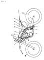
- Fig. 1 is a side view illustrating a motorcycle which is an example of a saddle-ride type vehicle to which one embodiment of a radiator shroud structure according to the present invention is applied.
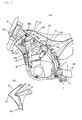
- Part (a) of Fig. 2 is a partially enlarged view of Fig. 1
- Part (b) thereof is a side view of a shroud.
- Fig. 3 is a partially enlarged plan view of Fig. 1 .
- Fig. 4 is a side view of a frame.
- Fig. 5 is a partially omitted plan view of the frame.
- a motorcycle illustrated in Figs. 1 to 3 includes: a vehicle-body frame 10 having a head pipe 11 and a pair of left and right main frames 12 (L, R) extending rearward from the head pipe 11 (see Fig. 3 ), the vehicle-body frame 10 supporting a fuel tank 20 between the left and right main frames 12 and supporting a radiator 30 below the left and right main frames 12; and radiator shrouds (sometimes called simply as shrouds) 40 covering lateral sides of the radiator 30.
- radiator shrouds sometimes called simply as shrouds
- Each of the shrouds 40 is fastened and fixed to shroud fastening portions 12b, 12d (see Figs. 4 and 5 ), which are provided on an outer side wall 12c of the main frame 12, by using fastening members 40b (bolts are illustrated in the drawings).
- Upper portions 41, 42 of the shroud 40 are arranged along an outer side face (12c) of the main frame 12, and a lower portion 43 of the shroud 40 extends downward from the upper portions 41, 42 and is coupled to the radiator 30. Any structure as appropriate may be employed for coupling the lower portion 43 of the shroud 40 and the radiator 30.
- the lower portion 43 of the shroud 40 and the radiator 30 are fastened and fixed by using a bolt 43b.
- the shroud 40 is fastened and fixed to the shroud fastening portions 12b, 12d (see Figs. 4 and 5 ), which are provided on the outer side wall 12c of the main frame 12, and the upper portions 41, 42 of the shroud 40 are arranged along the outer side face (12c) of the main frame 12, it is possible to protect the outer side face (12c) of the main frame 12 by using the upper portions 41, 42 of the shroud 40.
- the lower portion 43 of the shroud 40 extends downward from the upper portions 41, 42 and is coupled to the radiator 30, and the upper portions 41, 42 of the shroud 40 are arranged along the outer side face (12c) of the main frame 12, when stress is applied to the shroud 40 (for example, when external force is applied to a front end 44 of the shroud 40, or in a similar case), the upper portions 41, 42 of the shroud 40 abut on the outer side face (12c) of the main frame 12 and are restricted in position by the outer side face (12c). For this reason, it is possible to favorably suppress the deformation of the shroud 40.
- the shroud 40 is not fastened to the fuel tank 20, it is unnecessary to provide the fuel tank 20 with any fastening portion for the shroud 40. Therefore, it is possible to reduce the manufacturing cost for the fuel tank 20 and to achieve a favorable maintenance workability involving removal of the fuel tank 20.
- the fuel tank 20 is made of an expensive titanium material, providing the fuel tank 20 with no fastening portion allows for significant reduction in the cost of the fuel tank 20.
- the fuel tank 20 is provided with a tank cover 50 covering the fuel tank 20 from above.
- Lower sides 51 of the tank cover 50 are arranged along upper sides 12f of the main frames 12 in a side view.
- the shroud 40 is arranged such that the upper portions 41, 42 are arranged along the corresponding lower side 51 of the tank cover 50 and also flush with the lower side 51 of the tank cover 50.
- the upper portions 41, 42 of the shroud 40 are restricted in position by the main frame 12 across an entire vertical width W thereof, it is possible to receive deformation of the shroud 40 with a wide area and to thus disperse the stress.
- a reference numeral 2 denotes a step on which the rider places his/her foot
- 3 denotes a seat on which the rider sits down
- 4 denotes a handle to be steered by the rider.
- the handle 4 is turnably supported on the head pipe 11, and is used to steer a front wheel WF supported on a lower end of a front fork.
- a reference numeral 13 denotes their fastening and fixing portion.
- a pair of left and right attachment pieces 52, 22 are provided on a rear portion of the tank cover 50 and a rear portion of the fuel tank 20, respectively.
- the rear portion of the tank cover 50 and the rear portion of the fuel tank 20 are fixed to the main frames 12 by being fastened together to fixing portions 13d (see Figs. 4 and 5 ) of the main frame 12 by using bolts 13b with the attachment pieces 52, 22 being placed on each other.
- Front portions of the tank cover 50 and the tank cover 50 are also fixed to the vehicle-body frame 10 by being fastened together to a fixing portion 14d (see Figs. 4 and 5 ) provided on a coupling portion 14 between the main frames 12 (L, R) with a bolt 14b, which is a fastening member.
- a shroud fastening portion in the main frame 12 includes a front fastening portion 12b and a rear fastening portion 12d which are arranged on the front and rear sides, and the upper portions 41, 42 of the shroud 40 are fastened to the front fastening portion 12b and the rear fastening portion 12d by using the fastening members 40b.
- the lower portion 43 of the shroud 40 supports the radiator 30.
- any structure may be employed for connecting the lower portion 43 of the shroud 40 and the radiator 30 as appropriate.
- the lower portion 43 of the shroud 40 is fixed to the radiator 30 by using the fastening member (bolt or the like) 43b.
- the shroud 40 is fastened to the front fastening portion 12b, the rear fastening portion 12d, and the radiator 30 from the lateral side of the vehicle body.
- the shroud 40 includes a notch 45 located between the front fastening portion 12b and the rear fastening portion 12d and rearward of the radiator 30.
- a reference numeral E denotes an engine supported on the vehicle-body frame 10; 5 denotes a swingarm supported on the vehicle-body frame 10 and supporting a rear wheel WR at a rear end thereof; 6 denotes a cushion unit provided between the swingarm 5 and the vehicle-body frame 10 with a link 7 in between.
- a reference numeral 9 denotes a rear side cover, and 8 denotes a side cover. A side face of the tank cover 50, the side cover 8, and the rear side cover 9 form smoothly connected side faces of the vehicle.
- VEHICLE-BODY FRAME 11 HEAD PIPE 12: MAIN FRAME 12b, 12d: SHROUD FASTENING PORTION 12c: OUTER SIDE WALL (OUTER SIDE FACE) 12f: UPPER SIDE 20: FUEL TANK 30: RADIATOR 40: SHROUD 41, 42: UPPER PORTION 43: LOWER PORTION 45: NOTCH 50: TANK COVER 51: LOWER SIDE
Landscapes
- Engineering & Computer Science (AREA)
- Mechanical Engineering (AREA)
- Chemical & Material Sciences (AREA)
- Combustion & Propulsion (AREA)
- Transportation (AREA)
- Automatic Cycles, And Cycles In General (AREA)
- Cooling, Air Intake And Gas Exhaust, And Fuel Tank Arrangements In Propulsion Units (AREA)
Abstract
Description
- The present invention relates to a radiator shroud structure.
- A radiator shroud structure has conventionally been known which includes: a vehicle-body frame having a head pipe (2) and a pair of left and right main frames (10) extending rearward from the head pipe (2), the vehicle-body frame supporting a fuel tank (53) between the left and right main frames (10) and supporting a radiator (44) below the left and right main frames (10); and radiator shrouds (47) covering lateral sides of the radiator (44).
- A structure according to the prior art is known from Japanese Patent Application Publication No.
Hei 03-193585 - In the above-described conventional radiator shroud structure, upper portions of the radiator shrouds (47) are attached to attachment bosses (51) welded to lower portions of the main frames (10). For this reason, the main frames (10) are exposed, and outer faces of the main frames (10) are not protected.
- A problem to be solved by the present invention is to provide a radiator shroud structure capable of protecting outer faces of main frames.
- For the purpose of solving the above-mentioned problems, a radiator shroud structure of the present invention includes:
- a vehicle-body frame including a head pipe and a pair of left and right main frames extending rearward from the head pipe, the vehicle-body frame supporting a fuel tank between the left and right main frames and supporting a radiator below the left and right main frames; and
- radiator shrouds covering lateral sides of the radiator, in which
- each of the shrouds is fastened and fixed to a shroud fastening portion provided on an outer side wall of the corresponding main frame, an upper portion of the shroud is arranged along an outer side face of the main frame, and a lower portion of the shroud extends downward from the upper portion and is coupled to the radiator.
- With this radiator shroud structure, since the shroud is fastened and fixed to the shroud fastening portion provided on the outer side wall of the corresponding main frame and the upper portion of the shroud is arranged along the outer side face of the main frame, it is possible to protect the outer face of the main frame by using the upper portion of the shroud.
- Moreover, since the lower portion of the shroud extends downward from the upper portion and is coupled to the radiator and the upper portion of the shroud is arranged along the outer side face of the main frame, when stress is applied to the shroud, the upper portion of the shroud abuts on the outer side face of the main frame and is restricted in position by the outer side face. For this reason, it is possible to favorably suppress the deformation of the shroud.
- The radiator shroud structure may be configured such that
a tank cover covering the fuel tank from above is provided, lower sides of the tank cover are arranged along upper sides of the main frames in a side view, and
the shroud is arranged such that the upper portion of the shroud is arranged along the corresponding lower side of the tank cover and also flush with the lower side of the tank cover. - With this configuration, it is possible to favorably protect the outer side face of the main frame by using the upper portion of the shroud; also since the upper portion of the shroud and the lower side of the tank cover are flush with each other, it is possible for the rider to favorably move his/her legs.
- Furthermore, since the upper portion of the shroud is restricted in position by the main frame across an entire vertical width thereof, it is possible to receive deformation of the shroud with a wide area and to thus disperse the stress.
- The radiator shroud structure may be configured such that
the tank cover and the fuel tank are fastened and fixed to the vehicle-body frame by being fastened together from above. - With this configuration, it is possible to fasten and remove the tank cover and the shrouds separately, and to achieve a favorable maintainability because the work of removing the fuel tank can be conducted from above.
- The radiator shroud structure may be configured such that
the shroud fastening portion of each main frame includes a front fastening portion and a rear fastening portion which are arranged on front and rear sides, respectively,
the upper portion of the shroud is fastened to the front fastening portion and the rear fastening portion, and the lower portion of the shroud supports the radiator. - With this configuration, it is possible to support the radiator by using the shroud.
- The radiator shroud structure may be configured such that
the shroud is fastened to the front fastening portion, the rear fastening portion, and the radiator from a lateral side of a vehicle body. - With this configuration, it is possible to achieve a favorable workability for removing the shroud, and to thus achieve a favorable maintainability.
- The radiator shroud structure may be configured such that
the shroud includes a notch located between the front fastening portion and the rear fastening portion and rearward of the radiator. - With this configuration, since the front fastening portion and the rear fastening portion are not connected in a straight line, it is possible to achieve a shape with which force acting on one of the fastening portions is unlikely to affect the other fastening portion, and to cause a favorable flow of air to the outside at a position rearward of the radiator and to thus achieve a favorable cooling efficiency of the radiator.
-
Fig. 1 is a side view illustrating a motorcycle which is an example of a saddle-ride type vehicle to which one embodiment of a radiator shroud structure according to the present invention is applied. - Part (a) of
Fig. 2 is a partially enlarged view ofFig. 1 , and Part (b) thereof is a side view of a shroud. -
Fig. 3 is a partially enlarged plan view ofFig. 1 . -
Fig. 4 is a side view of a frame. -
Fig. 5 is a partially omitted plan view of the frame. - Hereinafter, an embodiment of a radiator shroud structure according to the present invention will be described with reference to the drawings. Note that in the drawings, the same or corresponding portions are denoted by the same reference numerals.
- A motorcycle illustrated in
Figs. 1 to 3 includes: a vehicle-body frame 10 having ahead pipe 11 and a pair of left and right main frames 12 (L, R) extending rearward from the head pipe 11 (seeFig. 3 ), the vehicle-body frame 10 supporting afuel tank 20 between the left and rightmain frames 12 and supporting aradiator 30 below the left and rightmain frames 12; and radiator shrouds (sometimes called simply as shrouds) 40 covering lateral sides of theradiator 30. - Each of the
shrouds 40 is fastened and fixed to shroud fasteningportions Figs. 4 and5 ), which are provided on anouter side wall 12c of themain frame 12, by using fasteningmembers 40b (bolts are illustrated in the drawings).Upper portions shroud 40 are arranged along an outer side face (12c) of themain frame 12, and alower portion 43 of theshroud 40 extends downward from theupper portions radiator 30. Any structure as appropriate may be employed for coupling thelower portion 43 of theshroud 40 and theradiator 30. In the drawings, thelower portion 43 of theshroud 40 and theradiator 30 are fastened and fixed by using abolt 43b. - With such radiator shroud structure, since the
shroud 40 is fastened and fixed to the shroud fasteningportions Figs. 4 and5 ), which are provided on theouter side wall 12c of themain frame 12, and theupper portions shroud 40 are arranged along the outer side face (12c) of themain frame 12, it is possible to protect the outer side face (12c) of themain frame 12 by using theupper portions shroud 40. - Moreover, since the
lower portion 43 of theshroud 40 extends downward from theupper portions radiator 30, and theupper portions shroud 40 are arranged along the outer side face (12c) of themain frame 12, when stress is applied to the shroud 40 (for example, when external force is applied to afront end 44 of theshroud 40, or in a similar case), theupper portions shroud 40 abut on the outer side face (12c) of themain frame 12 and are restricted in position by the outer side face (12c). For this reason, it is possible to favorably suppress the deformation of theshroud 40. - Moreover, since the
shroud 40 is not fastened to thefuel tank 20, it is unnecessary to provide thefuel tank 20 with any fastening portion for theshroud 40. Therefore, it is possible to reduce the manufacturing cost for thefuel tank 20 and to achieve a favorable maintenance workability involving removal of thefuel tank 20. In particular, when thefuel tank 20 is made of an expensive titanium material, providing thefuel tank 20 with no fastening portion allows for significant reduction in the cost of thefuel tank 20. - The
fuel tank 20 is provided with atank cover 50 covering thefuel tank 20 from above. -
Lower sides 51 of thetank cover 50 are arranged alongupper sides 12f of themain frames 12 in a side view. - The
shroud 40 is arranged such that theupper portions lower side 51 of thetank cover 50 and also flush with thelower side 51 of thetank cover 50. - With this configuration, it is possible to favorably protect the outer side face (12c) of the
main frame 12 by using theupper portions shroud 40; also since theupper portions shroud 40 and thelower side 51 of thetank cover 50 are flush with each other, it is possible for the rider to favorably move his/her legs. - Furthermore, since the
upper portions shroud 40 are restricted in position by themain frame 12 across an entire vertical width W thereof, it is possible to receive deformation of theshroud 40 with a wide area and to thus disperse the stress. - Note that in
Fig. 1 , areference numeral 2 denotes a step on which the rider places his/her foot; 3 denotes a seat on which the rider sits down; and 4 denotes a handle to be steered by the rider. Thehandle 4 is turnably supported on thehead pipe 11, and is used to steer a front wheel WF supported on a lower end of a front fork. - The
tank cover 50 and thefuel tank 20 are fastened and fixed to the vehicle-body frame 10 by being fastened together from above. InFigs. 2 and3 , areference numeral 13 denotes their fastening and fixing portion. - With this configuration, it is possible to fasten and remove the
tank cover 50 and theshrouds 40 separately, and to achieve a favorable maintainability because the work of removing thefuel tank 20 can be conducted from above. - A pair of left and
right attachment pieces tank cover 50 and a rear portion of thefuel tank 20, respectively. The rear portion of thetank cover 50 and the rear portion of thefuel tank 20 are fixed to themain frames 12 by being fastened together to fixingportions 13d (seeFigs. 4 and5 ) of themain frame 12 by usingbolts 13b with theattachment pieces tank cover 50 and thetank cover 50 are also fixed to the vehicle-body frame 10 by being fastened together to afixing portion 14d (seeFigs. 4 and5 ) provided on acoupling portion 14 between the main frames 12 (L, R) with abolt 14b, which is a fastening member. - A shroud fastening portion in the
main frame 12 includes afront fastening portion 12b and arear fastening portion 12d which are arranged on the front and rear sides, and theupper portions shroud 40 are fastened to thefront fastening portion 12b and therear fastening portion 12d by using thefastening members 40b. Thelower portion 43 of theshroud 40 supports theradiator 30. - With this configuration, it is possible to support the
radiator 30 by using theshroud 40. - Any structure may be employed for connecting the
lower portion 43 of theshroud 40 and theradiator 30 as appropriate. In this embodiment, thelower portion 43 of theshroud 40 is fixed to theradiator 30 by using the fastening member (bolt or the like) 43b. - The
shroud 40 is fastened to thefront fastening portion 12b, therear fastening portion 12d, and theradiator 30 from the lateral side of the vehicle body. - With this configuration, it is possible to achieve a favorable workability for removing the
shroud 40, and to thus achieve a favorable maintainability. - The
shroud 40 includes anotch 45 located between thefront fastening portion 12b and therear fastening portion 12d and rearward of theradiator 30. - With this configuration, since the
front fastening portion 12b and therear fastening portion 12d are not connected in a straight line, it is possible to achieve a shape with which force acting on one of the fastening portions is unlikely to affect the other fastening portion, and to cause a favorable flow of air to the outside at a position rearward of theradiator 30 and to thus achieve a favorable cooling efficiency of theradiator 30. - Note that in
Fig. 1 and the other drawings, a reference numeral E denotes an engine supported on the vehicle-body frame 10; 5 denotes a swingarm supported on the vehicle-body frame 10 and supporting a rear wheel WR at a rear end thereof; 6 denotes a cushion unit provided between theswingarm 5 and the vehicle-body frame 10 with alink 7 in between. Areference numeral 9 denotes a rear side cover, and 8 denotes a side cover. A side face of thetank cover 50, theside cover 8, and therear side cover 9 form smoothly connected side faces of the vehicle. - Although the embodiment of the present invention has been described so far, the present invention is not limited to the above-described embodiment, and may be modified as appropriate within the scope of the present invention.
-
10: VEHICLE-BODY FRAME 11: HEAD PIPE 12: MAIN FRAME 12b, 12d: SHROUD FASTENING PORTION 12c: OUTER SIDE WALL (OUTER SIDE FACE) 12f: UPPER SIDE 20: FUEL TANK 30: RADIATOR 40: SHROUD 41, 42: UPPER PORTION 43: LOWER PORTION 45: NOTCH 50: TANK COVER 51: LOWER SIDE
Claims (6)
- A radiator shroud structure comprising:a vehicle-body frame (10) including a head pipe (11) and a pair of left and right main frames (12) extending rearward from the head pipe (11), the vehicle-body frame (10) supporting a fuel tank (20) between the left and right main frames (12) and supporting a radiator (30) below the left and right main frames (12); andradiator shrouds (40) covering lateral sides of the radiator (30), whereineach of the shrouds (40) is fastened and fixed to a shroud fastening portion (12b, 12d) provided on an outer side wall (12c) of the corresponding main frame (12), an upper portion (41, 42) of the shroud (40) is arranged along an outer side face (12c) of the main frame (12), and a lower portion (43) of the shroud (40) extends downward from the upper portion (41, 42) and is coupled to the radiator (30).
- The radiator shroud structure according to claim 1, wherein
a tank cover (50) covering the fuel tank (20) from above is provided,
lower sides (51) of the tank cover (50) are arranged along upper sides (12f) of the main frames (12) in a side view, and
the shroud (40) is arranged such that the upper portion (41, 42) of the shroud (40) is arranged along the corresponding lower side (51) of the tank cover (50) and also flush with the lower side (51) of the tank cover (50). - The radiator shroud structure according to claim 2, wherein
the tank cover (50) and the fuel tank (20) are fastened and fixed to the vehicle-body frame (10) by being fastened together from above. - The radiator shroud structure according to any one of claims 1 to 3, wherein
the shroud fastening portion shroud fastening portion (12b, 12d) of each main frame (12) includes a front fastening portion (12b) and a rear fastening portion (12d) which are arranged on front and rear sides, respectively,
the upper portion (41, 42) of the shroud (40) is fastened to the front fastening portion (12b) and the rear fastening portion (12d), and
the lower portion (43) of the shroud (40) supports the radiator (30). - The radiator shroud structure according to any one of claims 1 to 4, wherein
the shroud (40) is fastened to the front fastening portion (12b), the rear fastening portion (12d), and the radiator (30) from a lateral side of a vehicle body. - The radiator shroud structure according to claim 4 or 5, wherein
the shroud (40) includes a notch (45) located between the front fastening portion (12b) and the rear fastening portion (12d) and rearward of the radiator (30).
Applications Claiming Priority (1)
| Application Number | Priority Date | Filing Date | Title |
|---|---|---|---|
| JP2014067898A JP6039601B2 (en) | 2014-03-28 | 2014-03-28 | Radiator shroud structure |
Publications (3)
| Publication Number | Publication Date |
|---|---|
| EP2923926A2 true EP2923926A2 (en) | 2015-09-30 |
| EP2923926A3 EP2923926A3 (en) | 2015-12-09 |
| EP2923926B1 EP2923926B1 (en) | 2017-02-08 |
Family
ID=52828964
Family Applications (1)
| Application Number | Title | Priority Date | Filing Date |
|---|---|---|---|
| EP15159355.5A Active EP2923926B1 (en) | 2014-03-28 | 2015-03-17 | Radiator shroud structure |
Country Status (3)
| Country | Link |
|---|---|
| US (1) | US9358875B2 (en) |
| EP (1) | EP2923926B1 (en) |
| JP (1) | JP6039601B2 (en) |
Cited By (6)
| Publication number | Priority date | Publication date | Assignee | Title |
|---|---|---|---|---|
| US11173808B2 (en) | 2016-12-22 | 2021-11-16 | Polaris Industies Inc. | Vehicle |
| US12172518B2 (en) | 2019-04-30 | 2024-12-24 | Polaris Industries Inc. | Vehicle |
| US12187127B2 (en) | 2020-05-15 | 2025-01-07 | Polaris Industries Inc. | Off-road vehicle |
| US12385429B2 (en) | 2022-06-13 | 2025-08-12 | Polaris Industries Inc. | Powertrain for a utility vehicle |
| US12384464B2 (en) | 2020-05-15 | 2025-08-12 | Polaris Industries Inc. | Off-road vehicle |
| US12552246B2 (en) | 2015-05-15 | 2026-02-17 | Polaris Industries Inc. | Utility vehicle |
Families Citing this family (4)
| Publication number | Priority date | Publication date | Assignee | Title |
|---|---|---|---|---|
| JP6282991B2 (en) * | 2015-03-13 | 2018-02-21 | 本田技研工業株式会社 | Body cover structure for saddle-ride type vehicles |
| JP6606040B2 (en) | 2016-09-09 | 2019-11-13 | 本田技研工業株式会社 | Body cover structure for saddle-ride type vehicles |
| JP6663451B2 (en) | 2018-04-26 | 2020-03-11 | 本田技研工業株式会社 | Saddle-type vehicle |
| JP7217308B2 (en) | 2021-03-31 | 2023-02-02 | 本田技研工業株式会社 | saddle-riding vehicle |
Citations (1)
| Publication number | Priority date | Publication date | Assignee | Title |
|---|---|---|---|---|
| JPH03193585A (en) | 1989-12-25 | 1991-08-23 | Yamaha Motor Co Ltd | Motorcycle |
Family Cites Families (13)
| Publication number | Priority date | Publication date | Assignee | Title |
|---|---|---|---|---|
| JPS6159187U (en) * | 1984-09-14 | 1986-04-21 | ||
| JPS62283081A (en) * | 1986-05-30 | 1987-12-08 | 本田技研工業株式会社 | Fairing device for motorcycle |
| JPH03258681A (en) * | 1990-03-09 | 1991-11-18 | Yamaha Motor Co Ltd | Body frame of motorcycle |
| DE69126556T2 (en) * | 1990-03-09 | 1997-10-02 | Yamaha Motor Co Ltd | Frame arrangement for motorcycle-like vehicle |
| JP3750879B2 (en) * | 1996-03-19 | 2006-03-01 | 本田技研工業株式会社 | Motorcycle cooling device |
| JP4511967B2 (en) * | 2005-02-07 | 2010-07-28 | 本田技研工業株式会社 | Rear support structure of shroud in motorcycle |
| JP4684715B2 (en) * | 2005-04-01 | 2011-05-18 | 川崎重工業株式会社 | Vehicle shroud |
| JP2007131257A (en) * | 2005-11-14 | 2007-05-31 | Yamaha Motor Co Ltd | Motorcycle |
| JP2008222079A (en) * | 2007-03-13 | 2008-09-25 | Yamaha Motor Co Ltd | Motorcycle |
| JP5551059B2 (en) * | 2010-12-22 | 2014-07-16 | 本田技研工業株式会社 | Saddle riding |
| JP5695515B2 (en) * | 2011-07-11 | 2015-04-08 | 本田技研工業株式会社 | Exterior cover for saddle-ride type vehicles |
| JP5725503B2 (en) * | 2011-07-11 | 2015-05-27 | 本田技研工業株式会社 | Exterior member of saddle riding type vehicle |
| JP5879064B2 (en) * | 2011-07-28 | 2016-03-08 | 本田技研工業株式会社 | Saddle riding vehicle |
-
2014
- 2014-03-28 JP JP2014067898A patent/JP6039601B2/en not_active Expired - Fee Related
-
2015
- 2015-03-17 EP EP15159355.5A patent/EP2923926B1/en active Active
- 2015-03-24 US US14/666,514 patent/US9358875B2/en active Active
Patent Citations (1)
| Publication number | Priority date | Publication date | Assignee | Title |
|---|---|---|---|---|
| JPH03193585A (en) | 1989-12-25 | 1991-08-23 | Yamaha Motor Co Ltd | Motorcycle |
Cited By (8)
| Publication number | Priority date | Publication date | Assignee | Title |
|---|---|---|---|---|
| US12552246B2 (en) | 2015-05-15 | 2026-02-17 | Polaris Industries Inc. | Utility vehicle |
| US11173808B2 (en) | 2016-12-22 | 2021-11-16 | Polaris Industies Inc. | Vehicle |
| US12208706B2 (en) | 2016-12-22 | 2025-01-28 | Polaris Industries Inc. | Vehicle |
| US12172518B2 (en) | 2019-04-30 | 2024-12-24 | Polaris Industries Inc. | Vehicle |
| US12187127B2 (en) | 2020-05-15 | 2025-01-07 | Polaris Industries Inc. | Off-road vehicle |
| US12337690B2 (en) | 2020-05-15 | 2025-06-24 | Polaris Industries Inc. | Off-road vehicle |
| US12384464B2 (en) | 2020-05-15 | 2025-08-12 | Polaris Industries Inc. | Off-road vehicle |
| US12385429B2 (en) | 2022-06-13 | 2025-08-12 | Polaris Industries Inc. | Powertrain for a utility vehicle |
Also Published As
| Publication number | Publication date |
|---|---|
| US9358875B2 (en) | 2016-06-07 |
| EP2923926B1 (en) | 2017-02-08 |
| US20150274001A1 (en) | 2015-10-01 |
| JP2015189328A (en) | 2015-11-02 |
| EP2923926A3 (en) | 2015-12-09 |
| JP6039601B2 (en) | 2016-12-07 |
Similar Documents
| Publication | Publication Date | Title |
|---|---|---|
| EP2923926A2 (en) | Radiator shroud structure | |
| JP6231920B2 (en) | Saddle riding vehicle | |
| JP2012071644A (en) | Motorcycle | |
| JP6118654B2 (en) | Motorcycle fuel tank support structure | |
| JP2009107564A (en) | Motorcycle | |
| JP6045903B2 (en) | Motorcycle | |
| US10661850B2 (en) | Front structure of saddled vehicle | |
| EP2781445B1 (en) | Straddle type vehicle | |
| JP5460511B2 (en) | Rear fender for vehicles | |
| US9248879B2 (en) | Fuel tank mounting structure of saddle-ride-type vehicle | |
| JP5658882B2 (en) | Rear structure of motorcycle | |
| ES2673795T3 (en) | Straddle Vehicle | |
| JP6313622B2 (en) | Saddle riding vehicle | |
| US9708022B2 (en) | Fuel tank mounting structure of saddle-ride-type vehicle | |
| JP6220702B2 (en) | Body frame structure of saddle riding type vehicle | |
| JP2009107566A (en) | Motorcycle | |
| JP2009161013A (en) | Motorcycle | |
| JP6244240B2 (en) | Saddle riding vehicle | |
| CN205186066U (en) | Tractor | |
| JP2017065272A (en) | Saddle-riding type vehicle | |
| EP3002187B1 (en) | Vehicle | |
| JP4301291B2 (en) | Body rigidity reinforcement structure | |
| JP6363445B2 (en) | Rear structure of motorcycle | |
| US9956945B2 (en) | Reservoir tank mounting structure of saddle riding vehicle | |
| JP6129693B2 (en) | Saddle riding type vehicle |
Legal Events
| Date | Code | Title | Description |
|---|---|---|---|
| PUAI | Public reference made under article 153(3) epc to a published international application that has entered the european phase |
Free format text: ORIGINAL CODE: 0009012 |
|
| 17P | Request for examination filed |
Effective date: 20150317 |
|
| AK | Designated contracting states |
Kind code of ref document: A2 Designated state(s): AL AT BE BG CH CY CZ DE DK EE ES FI FR GB GR HR HU IE IS IT LI LT LU LV MC MK MT NL NO PL PT RO RS SE SI SK SM TR |
|
| AX | Request for extension of the european patent |
Extension state: BA ME |
|
| PUAL | Search report despatched |
Free format text: ORIGINAL CODE: 0009013 |
|
| AK | Designated contracting states |
Kind code of ref document: A3 Designated state(s): AL AT BE BG CH CY CZ DE DK EE ES FI FR GB GR HR HU IE IS IT LI LT LU LV MC MK MT NL NO PL PT RO RS SE SI SK SM TR |
|
| AX | Request for extension of the european patent |
Extension state: BA ME |
|
| RIC1 | Information provided on ipc code assigned before grant |
Ipc: B62K 11/04 20060101ALI20151105BHEP Ipc: B62J 23/00 20060101ALI20151105BHEP Ipc: B62J 17/02 20060101AFI20151105BHEP |
|
| GRAP | Despatch of communication of intention to grant a patent |
Free format text: ORIGINAL CODE: EPIDOSNIGR1 |
|
| INTG | Intention to grant announced |
Effective date: 20160823 |
|
| RIN1 | Information on inventor provided before grant (corrected) |
Inventor name: HIRANO, KOHEI Inventor name: HOSOYA, KYOHEI Inventor name: MATSUO, TOMOYA |
|
| STAA | Information on the status of an ep patent application or granted ep patent |
Free format text: STATUS: GRANT OF PATENT IS INTENDED |
|
| GRAS | Grant fee paid |
Free format text: ORIGINAL CODE: EPIDOSNIGR3 |
|
| GRAA | (expected) grant |
Free format text: ORIGINAL CODE: 0009210 |
|
| STAA | Information on the status of an ep patent application or granted ep patent |
Free format text: STATUS: THE PATENT HAS BEEN GRANTED |
|
| AK | Designated contracting states |
Kind code of ref document: B1 Designated state(s): AL AT BE BG CH CY CZ DE DK EE ES FI FR GB GR HR HU IE IS IT LI LT LU LV MC MK MT NL NO PL PT RO RS SE SI SK SM TR |
|
| REG | Reference to a national code |
Ref country code: GB Ref legal event code: FG4D |
|
| REG | Reference to a national code |
Ref country code: CH Ref legal event code: EP Ref country code: AT Ref legal event code: REF Ref document number: 866738 Country of ref document: AT Kind code of ref document: T Effective date: 20170215 |
|
| REG | Reference to a national code |
Ref country code: FR Ref legal event code: PLFP Year of fee payment: 3 |
|
| REG | Reference to a national code |
Ref country code: IE Ref legal event code: FG4D |
|
| REG | Reference to a national code |
Ref country code: DE Ref legal event code: R096 Ref document number: 602015001454 Country of ref document: DE |
|
| REG | Reference to a national code |
Ref country code: LT Ref legal event code: MG4D |
|
| REG | Reference to a national code |
Ref country code: NL Ref legal event code: MP Effective date: 20170208 |
|
| REG | Reference to a national code |
Ref country code: AT Ref legal event code: MK05 Ref document number: 866738 Country of ref document: AT Kind code of ref document: T Effective date: 20170208 |
|
| PG25 | Lapsed in a contracting state [announced via postgrant information from national office to epo] |
Ref country code: GR Free format text: LAPSE BECAUSE OF FAILURE TO SUBMIT A TRANSLATION OF THE DESCRIPTION OR TO PAY THE FEE WITHIN THE PRESCRIBED TIME-LIMIT Effective date: 20170509 Ref country code: LT Free format text: LAPSE BECAUSE OF FAILURE TO SUBMIT A TRANSLATION OF THE DESCRIPTION OR TO PAY THE FEE WITHIN THE PRESCRIBED TIME-LIMIT Effective date: 20170208 Ref country code: HR Free format text: LAPSE BECAUSE OF FAILURE TO SUBMIT A TRANSLATION OF THE DESCRIPTION OR TO PAY THE FEE WITHIN THE PRESCRIBED TIME-LIMIT Effective date: 20170208 Ref country code: FI Free format text: LAPSE BECAUSE OF FAILURE TO SUBMIT A TRANSLATION OF THE DESCRIPTION OR TO PAY THE FEE WITHIN THE PRESCRIBED TIME-LIMIT Effective date: 20170208 Ref country code: NO Free format text: LAPSE BECAUSE OF FAILURE TO SUBMIT A TRANSLATION OF THE DESCRIPTION OR TO PAY THE FEE WITHIN THE PRESCRIBED TIME-LIMIT Effective date: 20170508 |
|
| PG25 | Lapsed in a contracting state [announced via postgrant information from national office to epo] |
Ref country code: SE Free format text: LAPSE BECAUSE OF FAILURE TO SUBMIT A TRANSLATION OF THE DESCRIPTION OR TO PAY THE FEE WITHIN THE PRESCRIBED TIME-LIMIT Effective date: 20170208 Ref country code: BG Free format text: LAPSE BECAUSE OF FAILURE TO SUBMIT A TRANSLATION OF THE DESCRIPTION OR TO PAY THE FEE WITHIN THE PRESCRIBED TIME-LIMIT Effective date: 20170508 Ref country code: AT Free format text: LAPSE BECAUSE OF FAILURE TO SUBMIT A TRANSLATION OF THE DESCRIPTION OR TO PAY THE FEE WITHIN THE PRESCRIBED TIME-LIMIT Effective date: 20170208 Ref country code: LV Free format text: LAPSE BECAUSE OF FAILURE TO SUBMIT A TRANSLATION OF THE DESCRIPTION OR TO PAY THE FEE WITHIN THE PRESCRIBED TIME-LIMIT Effective date: 20170208 Ref country code: ES Free format text: LAPSE BECAUSE OF FAILURE TO SUBMIT A TRANSLATION OF THE DESCRIPTION OR TO PAY THE FEE WITHIN THE PRESCRIBED TIME-LIMIT Effective date: 20170208 Ref country code: NL Free format text: LAPSE BECAUSE OF NON-PAYMENT OF DUE FEES Effective date: 20170208 Ref country code: RS Free format text: LAPSE BECAUSE OF FAILURE TO SUBMIT A TRANSLATION OF THE DESCRIPTION OR TO PAY THE FEE WITHIN THE PRESCRIBED TIME-LIMIT Effective date: 20170208 Ref country code: PT Free format text: LAPSE BECAUSE OF FAILURE TO SUBMIT A TRANSLATION OF THE DESCRIPTION OR TO PAY THE FEE WITHIN THE PRESCRIBED TIME-LIMIT Effective date: 20170608 |
|
| PG25 | Lapsed in a contracting state [announced via postgrant information from national office to epo] |
Ref country code: SK Free format text: LAPSE BECAUSE OF FAILURE TO SUBMIT A TRANSLATION OF THE DESCRIPTION OR TO PAY THE FEE WITHIN THE PRESCRIBED TIME-LIMIT Effective date: 20170208 Ref country code: RO Free format text: LAPSE BECAUSE OF FAILURE TO SUBMIT A TRANSLATION OF THE DESCRIPTION OR TO PAY THE FEE WITHIN THE PRESCRIBED TIME-LIMIT Effective date: 20170208 Ref country code: EE Free format text: LAPSE BECAUSE OF FAILURE TO SUBMIT A TRANSLATION OF THE DESCRIPTION OR TO PAY THE FEE WITHIN THE PRESCRIBED TIME-LIMIT Effective date: 20170208 Ref country code: CZ Free format text: LAPSE BECAUSE OF FAILURE TO SUBMIT A TRANSLATION OF THE DESCRIPTION OR TO PAY THE FEE WITHIN THE PRESCRIBED TIME-LIMIT Effective date: 20170208 |
|
| REG | Reference to a national code |
Ref country code: DE Ref legal event code: R097 Ref document number: 602015001454 Country of ref document: DE |
|
| PG25 | Lapsed in a contracting state [announced via postgrant information from national office to epo] |
Ref country code: MC Free format text: LAPSE BECAUSE OF FAILURE TO SUBMIT A TRANSLATION OF THE DESCRIPTION OR TO PAY THE FEE WITHIN THE PRESCRIBED TIME-LIMIT Effective date: 20170208 Ref country code: PL Free format text: LAPSE BECAUSE OF FAILURE TO SUBMIT A TRANSLATION OF THE DESCRIPTION OR TO PAY THE FEE WITHIN THE PRESCRIBED TIME-LIMIT Effective date: 20170208 Ref country code: SM Free format text: LAPSE BECAUSE OF FAILURE TO SUBMIT A TRANSLATION OF THE DESCRIPTION OR TO PAY THE FEE WITHIN THE PRESCRIBED TIME-LIMIT Effective date: 20170208 Ref country code: DK Free format text: LAPSE BECAUSE OF FAILURE TO SUBMIT A TRANSLATION OF THE DESCRIPTION OR TO PAY THE FEE WITHIN THE PRESCRIBED TIME-LIMIT Effective date: 20170208 |
|
| PLBE | No opposition filed within time limit |
Free format text: ORIGINAL CODE: 0009261 |
|
| STAA | Information on the status of an ep patent application or granted ep patent |
Free format text: STATUS: NO OPPOSITION FILED WITHIN TIME LIMIT |
|
| REG | Reference to a national code |
Ref country code: IE Ref legal event code: MM4A |
|
| 26N | No opposition filed |
Effective date: 20171109 |
|
| PG25 | Lapsed in a contracting state [announced via postgrant information from national office to epo] |
Ref country code: LU Free format text: LAPSE BECAUSE OF NON-PAYMENT OF DUE FEES Effective date: 20170317 |
|
| REG | Reference to a national code |
Ref country code: FR Ref legal event code: PLFP Year of fee payment: 4 |
|
| PG25 | Lapsed in a contracting state [announced via postgrant information from national office to epo] |
Ref country code: SI Free format text: LAPSE BECAUSE OF FAILURE TO SUBMIT A TRANSLATION OF THE DESCRIPTION OR TO PAY THE FEE WITHIN THE PRESCRIBED TIME-LIMIT Effective date: 20170208 Ref country code: IE Free format text: LAPSE BECAUSE OF NON-PAYMENT OF DUE FEES Effective date: 20170317 |
|
| REG | Reference to a national code |
Ref country code: BE Ref legal event code: MM Effective date: 20170331 |
|
| PG25 | Lapsed in a contracting state [announced via postgrant information from national office to epo] |
Ref country code: BE Free format text: LAPSE BECAUSE OF NON-PAYMENT OF DUE FEES Effective date: 20170331 |
|
| PGFP | Annual fee paid to national office [announced via postgrant information from national office to epo] |
Ref country code: IT Payment date: 20180331 Year of fee payment: 4 Ref country code: FR Payment date: 20180223 Year of fee payment: 4 |
|
| PG25 | Lapsed in a contracting state [announced via postgrant information from national office to epo] |
Ref country code: MT Free format text: LAPSE BECAUSE OF NON-PAYMENT OF DUE FEES Effective date: 20170317 |
|
| REG | Reference to a national code |
Ref country code: CH Ref legal event code: PL |
|
| PG25 | Lapsed in a contracting state [announced via postgrant information from national office to epo] |
Ref country code: LI Free format text: LAPSE BECAUSE OF NON-PAYMENT OF DUE FEES Effective date: 20180331 Ref country code: CH Free format text: LAPSE BECAUSE OF NON-PAYMENT OF DUE FEES Effective date: 20180331 |
|
| PG25 | Lapsed in a contracting state [announced via postgrant information from national office to epo] |
Ref country code: HU Free format text: LAPSE BECAUSE OF FAILURE TO SUBMIT A TRANSLATION OF THE DESCRIPTION OR TO PAY THE FEE WITHIN THE PRESCRIBED TIME-LIMIT; INVALID AB INITIO Effective date: 20150317 |
|
| PG25 | Lapsed in a contracting state [announced via postgrant information from national office to epo] |
Ref country code: CY Free format text: LAPSE BECAUSE OF FAILURE TO SUBMIT A TRANSLATION OF THE DESCRIPTION OR TO PAY THE FEE WITHIN THE PRESCRIBED TIME-LIMIT Effective date: 20170208 |
|
| GBPC | Gb: european patent ceased through non-payment of renewal fee |
Effective date: 20190317 |
|
| PG25 | Lapsed in a contracting state [announced via postgrant information from national office to epo] |
Ref country code: MK Free format text: LAPSE BECAUSE OF FAILURE TO SUBMIT A TRANSLATION OF THE DESCRIPTION OR TO PAY THE FEE WITHIN THE PRESCRIBED TIME-LIMIT Effective date: 20170208 |
|
| REG | Reference to a national code |
Ref country code: DE Ref legal event code: R084 Ref document number: 602015001454 Country of ref document: DE |
|
| PG25 | Lapsed in a contracting state [announced via postgrant information from national office to epo] |
Ref country code: GB Free format text: LAPSE BECAUSE OF NON-PAYMENT OF DUE FEES Effective date: 20190317 |
|
| PG25 | Lapsed in a contracting state [announced via postgrant information from national office to epo] |
Ref country code: IT Free format text: LAPSE BECAUSE OF NON-PAYMENT OF DUE FEES Effective date: 20190317 Ref country code: FR Free format text: LAPSE BECAUSE OF NON-PAYMENT OF DUE FEES Effective date: 20190331 |
|
| PG25 | Lapsed in a contracting state [announced via postgrant information from national office to epo] |
Ref country code: TR Free format text: LAPSE BECAUSE OF FAILURE TO SUBMIT A TRANSLATION OF THE DESCRIPTION OR TO PAY THE FEE WITHIN THE PRESCRIBED TIME-LIMIT Effective date: 20170208 |
|
| PG25 | Lapsed in a contracting state [announced via postgrant information from national office to epo] |
Ref country code: AL Free format text: LAPSE BECAUSE OF FAILURE TO SUBMIT A TRANSLATION OF THE DESCRIPTION OR TO PAY THE FEE WITHIN THE PRESCRIBED TIME-LIMIT Effective date: 20170208 Ref country code: IS Free format text: LAPSE BECAUSE OF FAILURE TO SUBMIT A TRANSLATION OF THE DESCRIPTION OR TO PAY THE FEE WITHIN THE PRESCRIBED TIME-LIMIT Effective date: 20170608 |
|
| PGFP | Annual fee paid to national office [announced via postgrant information from national office to epo] |
Ref country code: DE Payment date: 20260219 Year of fee payment: 12 |