EP2923816A1 - Procédé de rééquipement d'une souffleuse - Google Patents
Procédé de rééquipement d'une souffleuse Download PDFInfo
- Publication number
- EP2923816A1 EP2923816A1 EP15163092.8A EP15163092A EP2923816A1 EP 2923816 A1 EP2923816 A1 EP 2923816A1 EP 15163092 A EP15163092 A EP 15163092A EP 2923816 A1 EP2923816 A1 EP 2923816A1
- Authority
- EP
- European Patent Office
- Prior art keywords
- mold
- blow
- blow mold
- parts
- work area
- Prior art date
- Legal status (The legal status is an assumption and is not a legal conclusion. Google has not performed a legal analysis and makes no representation as to the accuracy of the status listed.)
- Granted
Links
- 238000000034 method Methods 0.000 title claims abstract description 52
- 238000007664 blowing Methods 0.000 title abstract description 4
- 238000000071 blow moulding Methods 0.000 claims abstract description 63
- 239000000969 carrier Substances 0.000 claims abstract description 24
- 230000008569 process Effects 0.000 claims abstract description 22
- 230000000694 effects Effects 0.000 claims description 7
- 230000008859 change Effects 0.000 claims description 6
- 238000010079 rubber tapping Methods 0.000 claims 1
- 238000006243 chemical reaction Methods 0.000 description 28
- 230000008901 benefit Effects 0.000 description 6
- 238000013461 design Methods 0.000 description 1
- 238000005429 filling process Methods 0.000 description 1
- 230000014759 maintenance of location Effects 0.000 description 1
- 230000007246 mechanism Effects 0.000 description 1
- 238000012986 modification Methods 0.000 description 1
- 230000004048 modification Effects 0.000 description 1
- 238000012545 processing Methods 0.000 description 1
- 238000012546 transfer Methods 0.000 description 1
Images


Classifications
-
- B—PERFORMING OPERATIONS; TRANSPORTING
- B29—WORKING OF PLASTICS; WORKING OF SUBSTANCES IN A PLASTIC STATE IN GENERAL
- B29C—SHAPING OR JOINING OF PLASTICS; SHAPING OF MATERIAL IN A PLASTIC STATE, NOT OTHERWISE PROVIDED FOR; AFTER-TREATMENT OF THE SHAPED PRODUCTS, e.g. REPAIRING
- B29C49/00—Blow-moulding, i.e. blowing a preform or parison to a desired shape within a mould; Apparatus therefor
- B29C49/42—Component parts, details or accessories; Auxiliary operations
-
- B—PERFORMING OPERATIONS; TRANSPORTING
- B29—WORKING OF PLASTICS; WORKING OF SUBSTANCES IN A PLASTIC STATE IN GENERAL
- B29C—SHAPING OR JOINING OF PLASTICS; SHAPING OF MATERIAL IN A PLASTIC STATE, NOT OTHERWISE PROVIDED FOR; AFTER-TREATMENT OF THE SHAPED PRODUCTS, e.g. REPAIRING
- B29C33/00—Moulds or cores; Details thereof or accessories therefor
- B29C33/30—Mounting, exchanging or centering
- B29C33/306—Exchangeable mould parts, e.g. cassette moulds, mould inserts
-
- B—PERFORMING OPERATIONS; TRANSPORTING
- B29—WORKING OF PLASTICS; WORKING OF SUBSTANCES IN A PLASTIC STATE IN GENERAL
- B29C—SHAPING OR JOINING OF PLASTICS; SHAPING OF MATERIAL IN A PLASTIC STATE, NOT OTHERWISE PROVIDED FOR; AFTER-TREATMENT OF THE SHAPED PRODUCTS, e.g. REPAIRING
- B29C49/00—Blow-moulding, i.e. blowing a preform or parison to a desired shape within a mould; Apparatus therefor
- B29C49/42—Component parts, details or accessories; Auxiliary operations
- B29C49/48—Moulds
- B29C2049/4856—Mounting, exchanging or centering moulds or parts thereof
- B29C2049/4858—Exchanging mould parts, e.g. for changing the mould size or geometry for making different products in the same mould
-
- B—PERFORMING OPERATIONS; TRANSPORTING
- B29—WORKING OF PLASTICS; WORKING OF SUBSTANCES IN A PLASTIC STATE IN GENERAL
- B29C—SHAPING OR JOINING OF PLASTICS; SHAPING OF MATERIAL IN A PLASTIC STATE, NOT OTHERWISE PROVIDED FOR; AFTER-TREATMENT OF THE SHAPED PRODUCTS, e.g. REPAIRING
- B29C49/00—Blow-moulding, i.e. blowing a preform or parison to a desired shape within a mould; Apparatus therefor
- B29C49/42—Component parts, details or accessories; Auxiliary operations
- B29C49/58—Blowing means
- B29C2049/5893—Mounting, exchanging or centering blowing means
-
- B—PERFORMING OPERATIONS; TRANSPORTING
- B29—WORKING OF PLASTICS; WORKING OF SUBSTANCES IN A PLASTIC STATE IN GENERAL
- B29C—SHAPING OR JOINING OF PLASTICS; SHAPING OF MATERIAL IN A PLASTIC STATE, NOT OTHERWISE PROVIDED FOR; AFTER-TREATMENT OF THE SHAPED PRODUCTS, e.g. REPAIRING
- B29C33/00—Moulds or cores; Details thereof or accessories therefor
- B29C33/0083—Electrical or fluid connection systems therefor
-
- B—PERFORMING OPERATIONS; TRANSPORTING
- B29—WORKING OF PLASTICS; WORKING OF SUBSTANCES IN A PLASTIC STATE IN GENERAL
- B29C—SHAPING OR JOINING OF PLASTICS; SHAPING OF MATERIAL IN A PLASTIC STATE, NOT OTHERWISE PROVIDED FOR; AFTER-TREATMENT OF THE SHAPED PRODUCTS, e.g. REPAIRING
- B29C49/00—Blow-moulding, i.e. blowing a preform or parison to a desired shape within a mould; Apparatus therefor
- B29C49/28—Blow-moulding apparatus
- B29C49/30—Blow-moulding apparatus having movable moulds or mould parts
- B29C49/36—Blow-moulding apparatus having movable moulds or mould parts rotatable about one axis
-
- B—PERFORMING OPERATIONS; TRANSPORTING
- B29—WORKING OF PLASTICS; WORKING OF SUBSTANCES IN A PLASTIC STATE IN GENERAL
- B29C—SHAPING OR JOINING OF PLASTICS; SHAPING OF MATERIAL IN A PLASTIC STATE, NOT OTHERWISE PROVIDED FOR; AFTER-TREATMENT OF THE SHAPED PRODUCTS, e.g. REPAIRING
- B29C49/00—Blow-moulding, i.e. blowing a preform or parison to a desired shape within a mould; Apparatus therefor
- B29C49/42—Component parts, details or accessories; Auxiliary operations
- B29C49/4273—Auxiliary operations after the blow-moulding operation not otherwise provided for
- B29C49/42808—Filling the article
-
- B—PERFORMING OPERATIONS; TRANSPORTING
- B29—WORKING OF PLASTICS; WORKING OF SUBSTANCES IN A PLASTIC STATE IN GENERAL
- B29C—SHAPING OR JOINING OF PLASTICS; SHAPING OF MATERIAL IN A PLASTIC STATE, NOT OTHERWISE PROVIDED FOR; AFTER-TREATMENT OF THE SHAPED PRODUCTS, e.g. REPAIRING
- B29C49/00—Blow-moulding, i.e. blowing a preform or parison to a desired shape within a mould; Apparatus therefor
- B29C49/42—Component parts, details or accessories; Auxiliary operations
- B29C49/64—Heating or cooling preforms, parisons or blown articles
- B29C49/66—Cooling by refrigerant introduced into the blown article
-
- B—PERFORMING OPERATIONS; TRANSPORTING
- B29—WORKING OF PLASTICS; WORKING OF SUBSTANCES IN A PLASTIC STATE IN GENERAL
- B29C—SHAPING OR JOINING OF PLASTICS; SHAPING OF MATERIAL IN A PLASTIC STATE, NOT OTHERWISE PROVIDED FOR; AFTER-TREATMENT OF THE SHAPED PRODUCTS, e.g. REPAIRING
- B29C49/00—Blow-moulding, i.e. blowing a preform or parison to a desired shape within a mould; Apparatus therefor
- B29C49/42—Component parts, details or accessories; Auxiliary operations
- B29C49/64—Heating or cooling preforms, parisons or blown articles
- B29C49/68—Ovens specially adapted for heating preforms or parisons
- B29C49/6835—Ovens specially adapted for heating preforms or parisons using reflectors
-
- Y—GENERAL TAGGING OF NEW TECHNOLOGICAL DEVELOPMENTS; GENERAL TAGGING OF CROSS-SECTIONAL TECHNOLOGIES SPANNING OVER SEVERAL SECTIONS OF THE IPC; TECHNICAL SUBJECTS COVERED BY FORMER USPC CROSS-REFERENCE ART COLLECTIONS [XRACs] AND DIGESTS
- Y10—TECHNICAL SUBJECTS COVERED BY FORMER USPC
- Y10T—TECHNICAL SUBJECTS COVERED BY FORMER US CLASSIFICATION
- Y10T29/00—Metal working
- Y10T29/49—Method of mechanical manufacture
- Y10T29/49716—Converting
-
- Y—GENERAL TAGGING OF NEW TECHNOLOGICAL DEVELOPMENTS; GENERAL TAGGING OF CROSS-SECTIONAL TECHNOLOGIES SPANNING OVER SEVERAL SECTIONS OF THE IPC; TECHNICAL SUBJECTS COVERED BY FORMER USPC CROSS-REFERENCE ART COLLECTIONS [XRACs] AND DIGESTS
- Y10—TECHNICAL SUBJECTS COVERED BY FORMER USPC
- Y10T—TECHNICAL SUBJECTS COVERED BY FORMER US CLASSIFICATION
- Y10T29/00—Metal working
- Y10T29/49—Method of mechanical manufacture
- Y10T29/49718—Repairing
- Y10T29/49721—Repairing with disassembling
- Y10T29/4973—Replacing of defective part
-
- Y—GENERAL TAGGING OF NEW TECHNOLOGICAL DEVELOPMENTS; GENERAL TAGGING OF CROSS-SECTIONAL TECHNOLOGIES SPANNING OVER SEVERAL SECTIONS OF THE IPC; TECHNICAL SUBJECTS COVERED BY FORMER USPC CROSS-REFERENCE ART COLLECTIONS [XRACs] AND DIGESTS
- Y10—TECHNICAL SUBJECTS COVERED BY FORMER USPC
- Y10T—TECHNICAL SUBJECTS COVERED BY FORMER US CLASSIFICATION
- Y10T29/00—Metal working
- Y10T29/49—Method of mechanical manufacture
- Y10T29/49815—Disassembling
Definitions
- the present invention relates to a method for converting a blow molding machine.
- the invention relates to a method of converting a blow molding machine comprising a plurality of multi-part mold carriers. Each of the mold carriers holds a multi-part blow mold.
- a blow molding machine is used in particular for stretch blow molding of preforms.
- the blow molding machine itself comprises at least one blow mold.
- blow molds are used, in which a preform with positive pressure inside the blow mold blown, ie, auskonturiert.
- the blow mold can be z. B. comprise two mold halves which are rotatably mounted about a common axis. By turning about this axis, the mold halves can be closed, so that forms a cavity in the inside of the limited by the two mold halves blow mold, in which a preform can be blown.
- the design of such a mold carrier is z. B. in the European patent EP 1 276 598 B1 disclosed.
- the European patent EP 0 572 107 B1 discloses a working head changer for a rotation system for treating containers.
- the rotation system comprises a rotatable body for conveying containers at a certain interval.
- a plurality of working heads are provided which are equidistantly spaced around the periphery of the rotatable body to subject each of the containers conveyed by the rotatable body to a treatment operation.
- the treatment process can, for. B. include a cover attachment process or a filling process.
- a connection is made between the rotatable body and each working head so as to detachably mount each working head onto the rotatable body.
- the working head changer comprises a control device for controlling the rotation of the rotatable body, so that each working head is stopped in succession and alternately at a predetermined working head changing station.
- a Working head feed mechanism provided which performs the corresponding change operation for the removal of a working head at the intended working head changing station. After the working head has been removed, a new working head can now be inserted at the space provided for this purpose.
- the German Offenlegungsschrift DE 10 2005 035 233 A1 discloses a device for holding blow mold segments.
- the blow mold segments are arranged in a support element.
- the blow mold segments are releasably fixable in the support element with at least one locking element.
- the locking element is designed both for providing a positive retention, as well as for providing a non-positive holder for the respective blow molding.
- the support member must be opened in a corresponding manner, so that the corresponding operations for the change of the blow mold segments must be performed in a single position.
- the object of the invention is to provide a method which allows a conversion of a blow molding machine, so that the changeover times for the conversion of the blow molding machine are reduced to a minimum.
- the mold carrier is opened on at least one first working area. At least one second working area, the multiple parts of the blow mold are removed from the mold carrier and replaced with a blow mold of a different type. Finally, the mold carrier is closed. It is also conceivable that the opening of the mold carrier takes place before the arrival of the mold carrier at the respective work area. Likewise, the closing of the mold carrier can be done after leaving the work area. For this example, a curve element can be used.
- a time required to perform the work on each of the plurality of work areas is such that the time spent on each of the work areas is about the same. This has the advantage that there is no waiting time when changing the mold carrier from at least one working area to the next. Waiting times are required when the work is completed on all work areas except one work area. With the change you have to wait for the "slowest" workspace. Of course, this leads to a non-optimal utilization of provided for the conversion of the blow molding machine downtime.
- the time required for the at least one working area for opening the mold carriers and for releasing the media connections is essentially the same as the time required for removing the blow mold, replacing the blow mold and closing the mold carrier and connecting the media feed.
- At a first work area the mold carrier is opened and the media connection is released.
- the multiple parts of the blow mold are removed from the mold carrier and replaced with a blow mold of a different type.
- the mold carriers are closed and the media supply is reconnected.
- the attachment for the parts of the blow mold are also solved.
- the fasteners for the parts of the blow mold can be tightened again. It is also conceivable that the fastenings for the parts of the blow mold are loosened and fixed in the station, in which the parts of the blow mold are exchanged for parts of a blow mold of a different type.
- the time required for the first working area for opening the mold carriers and for releasing the media connections be substantially equal to the time required for removing the blow mold and replacing the blow mold corresponds to the second work area. Furthermore, the time spent on the third work area for closing the mold carrier and connecting the media supply substantially the time required at the first and second work area correspond. It goes without saying that the time required in the first working area is reduced if the opening of the mold carriers takes place even before the mold carriers arrive at the first work area. Likewise, the time required for those working area will decrease if the closing of the mold carrier is not done in the designated working area.
- At least one robot is provided at the corresponding work area. This robot performs at least a part of the processes that are necessary for the conversion of the blow molding machine.
- the mold carriers are arranged on a transport device, wherein the transport device changes the mold carriers according to the cycle time between the work areas.
- the transport device can be designed linear. It is also conceivable that the transport device is designed as a wheel, wherein the wheel carries the plurality of mold carriers.
- a first blow mold half, a second blow mold half, a blow mold bottom part and a draft limiter are exchanged at the work area where the blow mold of another type is used.
- the replacement of the parts of the blow mold is carried out in one embodiment only when the Verrieglungen for the respective parts of the blow mold have been solved on the mold carrier. Accordingly, the lock must be closed again after inserting the parts in the mold carrier.
- the activity can be automatic or manual.
- Another embodiment is that the parts of the blow mold are first held on the mold carrier without a lock and that the locking takes place only by the closing of the mold carrier. Likewise, the lock is opened when the mold carrier is open. It is obvious to a person skilled in the art how to fasten and / or release the individual parts of the blow mold in the mold carrier.
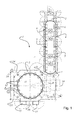
- FIG. 1 shows a schematic view of an apparatus with which plastic bottles can be prepared essentially by a stretch blow molding.
- the device 1 essentially consists of a furnace 2, in which preforms for the plastic bottles to be produced are brought to a specific temperature, so that the plastic bottles can be produced from these preforms by blow molding or stretch blow molding.
- the blowing machine 3 With the furnace 2, the blowing machine 3 is connected.
- a conveyor 4 In the furnace 2, a conveyor 4 is provided, which passes a plurality of preforms on a heater 5.
- the transport device 4 is shielded by means of heat-reflecting tiles 6.
- the preforms are introduced into the furnace 2.
- the heated preforms are transferred to an input position 9 for the blow molding machine 3.
- the finished plastic bottles are dispensed for further processing or for filling (not shown).
- the blow molding machine 3 comprises a transport device 11, on which the plurality of mold carriers 12 is arranged.
- the transport device 11 is designed as a wheel. It is also conceivable that the transport device 11 is designed as a substantially linear transport device.
- the blow molding machine 3 is surrounded by several walls 14. At least one wall 14 of the blow molding machine 3, a first working area 15, a second working area 16 and a third working area 17 are formed in the embodiment shown here. At these work areas 15, 16, 17, the conversion of the blow molding machine 3 can be performed. As already mentioned, the conversion of the blowing machine 3 can be carried out automatically at each of the working areas 15, 16 and 17.
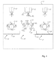
- FIG. 2 shows a schematic representation in which the mold carrier 12, which are arranged within the blow molding machine 3, the corresponding work areas 15, 16 and 17 are assigned, so that a corresponding conversion of the blow molding machine 3 can be performed.
- Illustrations shown to better illustrate the method of the mold carrier 12 is shown on the one hand in plan view and the other in a side view.
- the mold carrier 12 is constructed in several parts and thus carries the multi-part blow mold 22, which in the embodiment shown here consists of a first part of the blow mold 22 1 , a second part of the blow mold 22 2 and a third part of the blow mold 22 3 .
- the third part of the blow mold 22 3 is the bottom part, which ultimately forms the bottom shape of the plastic bottle to be produced.
- the first part of the blow mold 22 1 is connected to a corresponding media supply 20 1 .
- the second part of the blow mold 22 2 is connected to a corresponding media supply 20 2 .
- the third part of the blow mold 22 3 is connected to a corresponding media supply 20 3 .
- the mold carrier 12 is constructed proportionally, a closure element 24 is provided for locking the mold carrier 12. After the closure element 24 has been released, the mold carrier 12 can be divided. For the division of the mold carrier 12, this can be pivoted apart about an axis 26.
- the transport device 4 of the blow molding machine has been controlled such that in each case one of the working areas 15, 16 and 17 is opposed in each case by a mold carrier 12.
- the mold carriers 12 are in the in FIG. 2 all shown still closed.
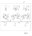
- FIG. 3 shows the situation of the inventive method for the conversion of a blow molding machine 3, in which at the first working area 15 of the mold carrier 12 has been pivoted apart about the axis 26. Furthermore, at this first work area 15, the respective media feeds 20 1 , 20 2 and 20 3 of the respective Parts of the blow molds 22 1 , 22 2 and 22 3 solved. As also from the FIG. 3 it can be seen, the respective work areas 15, 16 and 17 are provided with a corresponding shield 28. This shield 28 is provided for reasons of safety at work.
- FIG. 4 shows the situation of the inventive method for converting a blow molding machine 3, in which the transport device 4 of the blow molding machine 3 has transported the mold carrier 12 to the next working area.
- FIG. 4 is now the open in the first working area 15 mold carrier at the second working area 16. So that in the second working area 16, the parts of the blow molds 22 1 , 22 2 and 22 3 can be replaced, this is the shield 28 of the second working area 16 is removed, or pushed aside.
- the mold carrier 12 located in the second working region 16 is thus accessible for the manual or automatic handling of the process for the conversion of the blow molding machine 3.
- FIG. 5 shows the situation of the process for the conversion of the blow molding machine 3, in which processes are respectively carried out on the mold carrier 12 for the conversion of the blow molding machine 3 at the first working area 15 and at the second working area 16. While the individual parts of the blow mold 22 1 , 22 2 and 22 3 are exchanged at the second working area 16, the mold carrier 12 is opened at the first working area 15 and the media feeds 20 1 , 20 2 and 20 3 are released . The shield 28 in front of the second working area 16 is removed to allow the replacement of the parts of the blow mold 22 1 , 22 2 and 22 3 . It is of particular advantage if the time required to carry out the activities in the first work area 15 and the time required to carry out the work in the second work area 16 are approximately the same.
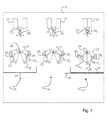
- FIG. 6 shows the situation of the method for converting the blow molding machine 3, in which the mold carrier 12, which the second work area 16 from FIG. 5 has now been transported to the third work area 17.
- the further transport of the mold carriers 12 from one work area to the next work area is then carried out when the activities or processes at the respective work areas 15, 16 and 17 are completed.
- the cycle time of the transport device 4 has to be directed to that work area, which requires the greatest amount of time to carry out the activities.
- the best thing is when the time spent on each of the work areas would be the same for carrying out the activities required there. This would lead to an optimal use of the downtime of the blow molding machine 3.
- FIG. 1 shows the situation of the method for converting the blow molding machine 3, in which the mold carrier 12, which the second work area 16 from FIG. 5 has now been transported to the third work area 17.
- the further transport of the mold carriers 12 from one work area to the next work area is then carried out when the activities or processes at the respective work areas 15, 16 and 17 are completed.
- FIG. 7 represents the situation of the method for converting a blow molding machine 3, in which activities are performed on all working areas 15, 16 and 17.
- the mold carrier 12 is opened.
- the closure element 24 is released and the mold carrier is pivoted about the axis 26 and thus divided.
- the media feeds 20 1 , 20 2 and 20 3 are released from the respectively associated parts of the blow mold 22 1 , 22 2 and 22 3 .
- the shield 28 is opened and the parts of the blow mold 22 1 , 22 2 and 22 3 replaced with other parts of another type of blow mold.
Landscapes
- Engineering & Computer Science (AREA)
- Mechanical Engineering (AREA)
- Manufacturing & Machinery (AREA)
- Blow-Moulding Or Thermoforming Of Plastics Or The Like (AREA)
- Moulds For Moulding Plastics Or The Like (AREA)
Applications Claiming Priority (2)
| Application Number | Priority Date | Filing Date | Title |
|---|---|---|---|
| DE102008004773.2A DE102008004773B4 (de) | 2008-01-16 | 2008-01-16 | Verfahren zum Umrüsten einer Blasmaschine |
| EP08171217.6A EP2080606B1 (fr) | 2008-01-16 | 2008-12-10 | Procédé de rééquipement d'une souffleuse |
Related Parent Applications (2)
| Application Number | Title | Priority Date | Filing Date |
|---|---|---|---|
| EP08171217.6A Division EP2080606B1 (fr) | 2008-01-16 | 2008-12-10 | Procédé de rééquipement d'une souffleuse |
| EP08171217.6A Division-Into EP2080606B1 (fr) | 2008-01-16 | 2008-12-10 | Procédé de rééquipement d'une souffleuse |
Publications (2)
| Publication Number | Publication Date |
|---|---|
| EP2923816A1 true EP2923816A1 (fr) | 2015-09-30 |
| EP2923816B1 EP2923816B1 (fr) | 2021-08-18 |
Family
ID=40547832
Family Applications (2)
| Application Number | Title | Priority Date | Filing Date |
|---|---|---|---|
| EP15163092.8A Active EP2923816B1 (fr) | 2008-01-16 | 2008-12-10 | Procédé de rééquipement d'une souffleuse |
| EP08171217.6A Active EP2080606B1 (fr) | 2008-01-16 | 2008-12-10 | Procédé de rééquipement d'une souffleuse |
Family Applications After (1)
| Application Number | Title | Priority Date | Filing Date |
|---|---|---|---|
| EP08171217.6A Active EP2080606B1 (fr) | 2008-01-16 | 2008-12-10 | Procédé de rééquipement d'une souffleuse |
Country Status (4)
| Country | Link |
|---|---|
| US (2) | US8069545B2 (fr) |
| EP (2) | EP2923816B1 (fr) |
| CN (2) | CN101486251B (fr) |
| DE (1) | DE102008004773B4 (fr) |
Families Citing this family (32)
| Publication number | Priority date | Publication date | Assignee | Title |
|---|---|---|---|---|
| DE102009035871A1 (de) * | 2009-07-31 | 2011-02-03 | Krones Ag | Schnellwechselmechansimus für Bodenteile |
| DE102009039699A1 (de) * | 2009-09-02 | 2011-04-28 | Krones Ag | Verfahren und Vorrichtung zur Montage und/oder Demontage von Blasformen |
| DE102009039700A1 (de) * | 2009-09-02 | 2011-03-10 | Krones Ag | Magazinvorrichtung zur Aufbewahrung von Blasformen |
| DE102009039695B4 (de) * | 2009-09-02 | 2020-08-13 | Krones Aktiengesellschaft | Verfahren und Vorrichtung zur Montage und/oder Demontage von Blasformen |
| WO2011026981A1 (fr) * | 2009-09-07 | 2011-03-10 | Sidel Participations | Procede de changement d ' un moule |
| FR2949704B1 (fr) * | 2009-09-07 | 2011-11-25 | Sidel Participations | Procede de changement des empreintes de moulage d'une station de soufflage de recipients en plastique |
| FR2949709B1 (fr) * | 2009-09-08 | 2011-10-07 | Sidel Participations | Machine pour la fabrication de recipients comportant un module de commande de dispositifs d'une unite de moulage en vue d'operer un changement de moule |
| DE102009040978A1 (de) * | 2009-09-11 | 2011-03-17 | Krones Ag | Magazinvorrichtung für Blasformen mit Reinigungseinrichtung |
| DE102009040977B4 (de) * | 2009-09-11 | 2022-12-15 | Krones Aktiengesellschaft | Behältnisbehandlungsanlage und ein Behältnisbehandlungsverfahren zum Behandeln von mit einem Produkt befüllbaren Behältnissen |
| FR2954207B1 (fr) * | 2009-12-21 | 2013-09-27 | Sidel Participations | Machine pour la fabrication de recipients comportant un systeme d'assistance au changement de moule |
| DE102010048720A1 (de) * | 2010-10-19 | 2012-04-19 | Krones Aktiengesellschaft | Schnellmontierbare Bodenform mit zuschaltbarer Haltekraftunterstützung |
| FR2972385B1 (fr) * | 2011-03-08 | 2013-04-26 | Sidel Participations | Systeme automatise pour le changement de moule d'une unite de moulage equipant une machine de fabrication de recipients |
| FR2972386B1 (fr) * | 2011-03-08 | 2014-10-10 | Sidel Participations | Systeme d'assistance au changement de moule d'unite de moulage d'une machine de fabrication de recipients |
| DE102011050724A1 (de) | 2011-05-30 | 2012-12-06 | Krones Aktiengesellschaft | Simultanes Umrüsten von Verarbeitungsvorrichtungen |
| DE102011053577A1 (de) * | 2011-09-13 | 2013-03-14 | Krones Aktiengesellschaft | Blasmaschine mit demontierbaren Blasstationen |
| DE102011054890A1 (de) * | 2011-10-28 | 2013-05-02 | Krones Aktiengesellschaft | Behälterbehandlungsanlage und Handhabungsvorrichtung |
| FR2990639B1 (fr) * | 2012-05-21 | 2014-06-13 | Sidel Participations | "installation pour la fabrication de recipients comportant un robot agence pour intervenir sur au moins deux unites" |
| DE102013100627A1 (de) | 2013-01-22 | 2014-07-24 | Krones Aktiengesellschaft | Verfahren zum betreiben einer behälterbehandlungsanlage und behälterbehandlungsanlage |
| DE102013113076A1 (de) | 2013-11-26 | 2015-05-28 | Krones Ag | Blasformmaschine mit Wechselroboter und Verfahren zu deren Betrieb |
| CN103692642B (zh) * | 2013-12-23 | 2016-01-20 | 冯伟君 | 吹塑机的模架结构 |
| DE102014105762A1 (de) * | 2014-04-24 | 2015-11-12 | Krones Ag | Blasformmaschine mit automatisch betätigbarer Bodenankopplung |
| DE102015116037A1 (de) * | 2015-09-23 | 2017-03-23 | Krones Ag | Vorrichtung und Verfahren zur Durchführung eines Umstellvorganges bei einer Getränkeherstellungsanlage |
| US10647047B2 (en) * | 2015-10-09 | 2020-05-12 | Krones Ag | Blow molding machine with automatically actuated base coupling |
| JP6789139B2 (ja) * | 2016-03-31 | 2020-11-25 | サントリーホールディングス株式会社 | ブロー成形機に対する金型交換作業用の作業器具、及び、その作業器具を用いた作業方法 |
| DE102017110270A1 (de) * | 2017-05-11 | 2018-11-15 | Krones Ag | Verfahren zum Sterilisieren einer Blasformmaschine und Blasformmaschine |
| DE102017110272A1 (de) | 2017-05-11 | 2018-11-15 | Krones Ag | Verfahren zum Sterilisieren einer Blasformmaschine und Blasformmaschine |
| DE102017209838A1 (de) * | 2017-06-12 | 2018-12-13 | Krones Ag | Behälterbehandlungsanlage zum Behandeln von Behältern |
| CN212888874U (zh) * | 2017-08-02 | 2021-04-06 | 克朗斯股份公司 | 用于将塑料预成型件成型为塑料容器的设备 |
| DE102017120774A1 (de) | 2017-09-08 | 2019-03-14 | Krones Ag | Vorrichtung und Verfahren zum Umformen von Kunststoffvorformlingen zu Kunststoffbehältnissen mit Wechselroboter |
| CN107839194B (zh) * | 2017-10-24 | 2020-02-07 | 重庆德洋中车汽车零部件有限公司 | 一种材料快速供给塑料吹塑机 |
| CN113478787B (zh) * | 2021-07-09 | 2022-04-01 | 临安东宸塑件有限公司 | 一种吹塑机 |
| DE102022115509A1 (de) * | 2022-06-22 | 2023-12-28 | Khs Gmbh | Verfahren und Austauschvorrichtung zum automatisierten Austauschen einer äußeren Form einer Umformstation gegen eine Wechselform |
Citations (6)
| Publication number | Priority date | Publication date | Assignee | Title |
|---|---|---|---|---|
| US4035463A (en) * | 1968-01-16 | 1977-07-12 | Heidenreich & Harbeck | Method of making hollow articles, especially bottles, of thermoplastics |
| EP0572107B1 (fr) | 1992-05-29 | 1996-09-04 | Shibuya Kogyo Co., Ltd | Changeur de têtes de travail pour un système rotatif de traitement de récipients |
| US6447281B1 (en) * | 1998-09-11 | 2002-09-10 | Sidel, Inc. | Blow mold shell and shell holder assembly for blow-molding machine |
| EP1276598B1 (fr) | 2000-04-22 | 2005-08-24 | Krones Ag | Moule et machine de soufflage |
| DE102005035233A1 (de) | 2005-07-25 | 2007-04-12 | Sig Technology Ag | Vorrichtung zur Halterung von Blasformsegmenten |
| DE102007005489A1 (de) * | 2007-01-30 | 2007-07-26 | Bachmann Gmbh | Rundgetaktete Maschine, insbesondere Blasformmaschine |
Family Cites Families (9)
| Publication number | Priority date | Publication date | Assignee | Title |
|---|---|---|---|---|
| JPS6045045B2 (ja) * | 1977-12-27 | 1985-10-07 | 株式会社吉野工業所 | 延伸ブロ−成形装置 |
| JPS5590318A (en) * | 1978-12-28 | 1980-07-08 | Yoshino Kogyosho Co Ltd | Heat rolling blow molding apparatus |
| JP2545088Y2 (ja) | 1991-10-25 | 1997-08-25 | 株式会社クラタ | ブロー成形機用部品交換装置 |
| AUPN496195A0 (en) * | 1995-08-22 | 1995-09-14 | Aci Operations Pty. Limited | Improved process for mould replacement |
| US6648623B2 (en) * | 1999-02-05 | 2003-11-18 | Sidel, Inc. | Quick change blow mold shell assembly |
| US6613262B1 (en) * | 2000-10-31 | 2003-09-02 | Donald P. Arend | Molding system with movable mold modules |
| JP4285727B2 (ja) * | 2002-11-08 | 2009-06-24 | 株式会社フロンティア | ブロー成形装置の移送機構 |
| DE102005011805A1 (de) * | 2005-03-15 | 2007-01-11 | Sig Technology Ltd. | Verfahren und Vorrichtung zur Blasformung von Behältern |
| US7335007B2 (en) * | 2005-04-18 | 2008-02-26 | Graham Packaging Company, L.P. | Quick change mold |
-
2008
- 2008-01-16 DE DE102008004773.2A patent/DE102008004773B4/de active Active
- 2008-12-10 EP EP15163092.8A patent/EP2923816B1/fr active Active
- 2008-12-10 EP EP08171217.6A patent/EP2080606B1/fr active Active
-
2009
- 2009-01-15 CN CN2009100015909A patent/CN101486251B/zh active Active
- 2009-01-15 US US12/321,018 patent/US8069545B2/en active Active
- 2009-01-15 CN CN2013103195365A patent/CN103395143A/zh active Pending
-
2011
- 2011-10-27 US US13/282,718 patent/US20120036693A1/en not_active Abandoned
Patent Citations (6)
| Publication number | Priority date | Publication date | Assignee | Title |
|---|---|---|---|---|
| US4035463A (en) * | 1968-01-16 | 1977-07-12 | Heidenreich & Harbeck | Method of making hollow articles, especially bottles, of thermoplastics |
| EP0572107B1 (fr) | 1992-05-29 | 1996-09-04 | Shibuya Kogyo Co., Ltd | Changeur de têtes de travail pour un système rotatif de traitement de récipients |
| US6447281B1 (en) * | 1998-09-11 | 2002-09-10 | Sidel, Inc. | Blow mold shell and shell holder assembly for blow-molding machine |
| EP1276598B1 (fr) | 2000-04-22 | 2005-08-24 | Krones Ag | Moule et machine de soufflage |
| DE102005035233A1 (de) | 2005-07-25 | 2007-04-12 | Sig Technology Ag | Vorrichtung zur Halterung von Blasformsegmenten |
| DE102007005489A1 (de) * | 2007-01-30 | 2007-07-26 | Bachmann Gmbh | Rundgetaktete Maschine, insbesondere Blasformmaschine |
Also Published As
| Publication number | Publication date |
|---|---|
| EP2080606A2 (fr) | 2009-07-22 |
| CN101486251B (zh) | 2013-08-28 |
| CN101486251A (zh) | 2009-07-22 |
| CN103395143A (zh) | 2013-11-20 |
| DE102008004773A1 (de) | 2009-07-23 |
| EP2080606A3 (fr) | 2010-02-24 |
| US20090178264A1 (en) | 2009-07-16 |
| EP2080606B1 (fr) | 2015-09-09 |
| US8069545B2 (en) | 2011-12-06 |
| DE102008004773B4 (de) | 2022-03-10 |
| EP2923816B1 (fr) | 2021-08-18 |
| US20120036693A1 (en) | 2012-02-16 |
Similar Documents
| Publication | Publication Date | Title |
|---|---|---|
| EP2080606B1 (fr) | Procédé de rééquipement d'une souffleuse | |
| EP2918391B1 (fr) | Dispositif et procédé de transformation d'ébauches en matière synthétique en récipients en plastique à l'aide de dispositif de changement automatique pour des parties de garnitures | |
| EP2771245B1 (fr) | Installation de traitement de contenants et dispositif de manipulation | |
| EP2292402B1 (fr) | Dispositif de stockage et procédé pour stocker des moules de soufflage | |
| EP2292403B1 (fr) | Procédé et dispositif de démontage de moules de soufflage | |
| DE2051396C3 (de) | Vorrichtung zum Kühlen von in einem Formhalter lösbar befestigten Külbelformen | |
| EP0293665A2 (fr) | Procédé et appareil pour la fabrication de brosses en matériau plastique | |
| DE202012013536U1 (de) | System zur Unterstützung beim Formenwechsel der Blasstation einer Behälterproduktionsmaschine | |
| DE102013100627A1 (de) | Verfahren zum betreiben einer behälterbehandlungsanlage und behälterbehandlungsanlage | |
| DE1479041A1 (de) | Blasformmaschine | |
| EP1651372B1 (fr) | Dispositif de fabrication de paquets de noyaux | |
| DE102012008939A1 (de) | Spritzgießmaschine | |
| DE19506599C2 (de) | Spritzgußmaschine | |
| EP1343626B1 (fr) | Dispositif et procede de fabrication de contenants par soufflage | |
| DE102008021526A1 (de) | Vorrichtung zum Expandieren von Kunststoffbehältnissen | |
| DE102008064888B3 (de) | Blasmaschine zum Streckblasen von Vorformlingen | |
| DE102008064841B3 (de) | Verfahren zum Umrüsten einer Blasmaschine | |
| DE202008018655U1 (de) | Vorrichtung zum Umrüsten einer Blasmaschine | |
| WO2005014203A2 (fr) | Dispositif pour la fabrication d'assemblages de noyaux | |
| EP0462990B1 (fr) | Dispositif de transport de noyaux et de moules de coulee | |
| DE3723830A1 (de) | Wechselvorrichtung fuer die formwerkzeuge von spritzgiessmaschinen | |
| EP1048435A1 (fr) | Procédé et appareil de moulage par injection-soufflage | |
| DE1704300A1 (de) | Spritz- und Blasanlage fuer Kunststoffe |
Legal Events
| Date | Code | Title | Description |
|---|---|---|---|
| PUAI | Public reference made under article 153(3) epc to a published international application that has entered the european phase |
Free format text: ORIGINAL CODE: 0009012 |
|
| AC | Divisional application: reference to earlier application |
Ref document number: 2080606 Country of ref document: EP Kind code of ref document: P |
|
| AK | Designated contracting states |
Kind code of ref document: A1 Designated state(s): AT DE ES FR GB IT |
|
| 17P | Request for examination filed |
Effective date: 20160324 |
|
| RBV | Designated contracting states (corrected) |
Designated state(s): AT DE ES FR GB IT |
|
| STAA | Information on the status of an ep patent application or granted ep patent |
Free format text: STATUS: EXAMINATION IS IN PROGRESS |
|
| 17Q | First examination report despatched |
Effective date: 20180209 |
|
| STAA | Information on the status of an ep patent application or granted ep patent |
Free format text: STATUS: EXAMINATION IS IN PROGRESS |
|
| GRAP | Despatch of communication of intention to grant a patent |
Free format text: ORIGINAL CODE: EPIDOSNIGR1 |
|
| STAA | Information on the status of an ep patent application or granted ep patent |
Free format text: STATUS: GRANT OF PATENT IS INTENDED |
|
| RIC1 | Information provided on ipc code assigned before grant |
Ipc: B29C 49/42 20060101AFI20210301BHEP Ipc: B29C 33/00 20060101ALN20210301BHEP Ipc: B29C 33/30 20060101ALI20210301BHEP Ipc: B29C 33/34 20060101ALI20210301BHEP Ipc: B29C 49/06 20060101ALN20210301BHEP Ipc: B29C 49/36 20060101ALN20210301BHEP Ipc: B29C 49/48 20060101ALN20210301BHEP Ipc: B29C 49/66 20060101ALN20210301BHEP |
|
| INTG | Intention to grant announced |
Effective date: 20210317 |
|
| RIN1 | Information on inventor provided before grant (corrected) |
Inventor name: STOIBER, CHRISTIAN |
|
| GRAS | Grant fee paid |
Free format text: ORIGINAL CODE: EPIDOSNIGR3 |
|
| GRAA | (expected) grant |
Free format text: ORIGINAL CODE: 0009210 |
|
| STAA | Information on the status of an ep patent application or granted ep patent |
Free format text: STATUS: THE PATENT HAS BEEN GRANTED |
|
| AC | Divisional application: reference to earlier application |
Ref document number: 2080606 Country of ref document: EP Kind code of ref document: P |
|
| AK | Designated contracting states |
Kind code of ref document: B1 Designated state(s): AT DE ES FR GB IT |
|
| REG | Reference to a national code |
Ref country code: GB Ref legal event code: FG4D Free format text: NOT ENGLISH |
|
| REG | Reference to a national code |
Ref country code: DE Ref legal event code: R096 Ref document number: 502008017225 Country of ref document: DE |
|
| REG | Reference to a national code |
Ref country code: AT Ref legal event code: REF Ref document number: 1421241 Country of ref document: AT Kind code of ref document: T Effective date: 20210915 |
|
| PG25 | Lapsed in a contracting state [announced via postgrant information from national office to epo] |
Ref country code: ES Free format text: LAPSE BECAUSE OF FAILURE TO SUBMIT A TRANSLATION OF THE DESCRIPTION OR TO PAY THE FEE WITHIN THE PRESCRIBED TIME-LIMIT Effective date: 20210818 |
|
| REG | Reference to a national code |
Ref country code: DE Ref legal event code: R097 Ref document number: 502008017225 Country of ref document: DE |
|
| PLBE | No opposition filed within time limit |
Free format text: ORIGINAL CODE: 0009261 |
|
| STAA | Information on the status of an ep patent application or granted ep patent |
Free format text: STATUS: NO OPPOSITION FILED WITHIN TIME LIMIT |
|
| 26N | No opposition filed |
Effective date: 20220519 |
|
| GBPC | Gb: european patent ceased through non-payment of renewal fee |
Effective date: 20211210 |
|
| PG25 | Lapsed in a contracting state [announced via postgrant information from national office to epo] |
Ref country code: GB Free format text: LAPSE BECAUSE OF NON-PAYMENT OF DUE FEES Effective date: 20211210 |
|
| REG | Reference to a national code |
Ref country code: AT Ref legal event code: MM01 Ref document number: 1421241 Country of ref document: AT Kind code of ref document: T Effective date: 20211210 |
|
| PG25 | Lapsed in a contracting state [announced via postgrant information from national office to epo] |
Ref country code: AT Free format text: LAPSE BECAUSE OF NON-PAYMENT OF DUE FEES Effective date: 20211210 |
|
| P01 | Opt-out of the competence of the unified patent court (upc) registered |
Effective date: 20230523 |
|
| PGFP | Annual fee paid to national office [announced via postgrant information from national office to epo] |
Ref country code: IT Payment date: 20231110 Year of fee payment: 16 Ref country code: FR Payment date: 20231108 Year of fee payment: 16 Ref country code: DE Payment date: 20231031 Year of fee payment: 16 |