EP2923656A1 - Tissue ablation apparatus - Google Patents
Tissue ablation apparatus Download PDFInfo
- Publication number
- EP2923656A1 EP2923656A1 EP13856141.0A EP13856141A EP2923656A1 EP 2923656 A1 EP2923656 A1 EP 2923656A1 EP 13856141 A EP13856141 A EP 13856141A EP 2923656 A1 EP2923656 A1 EP 2923656A1
- Authority
- EP
- European Patent Office
- Prior art keywords
- tissue
- pair
- slot
- ablation apparatus
- distal end
- Prior art date
- Legal status (The legal status is an assumption and is not a legal conclusion. Google has not performed a legal analysis and makes no representation as to the accuracy of the status listed.)
- Withdrawn
Links
- 238000002679 ablation Methods 0.000 title claims abstract description 87
- 238000007789 sealing Methods 0.000 claims abstract description 66
- 230000033001 locomotion Effects 0.000 claims abstract description 3
- 238000003780 insertion Methods 0.000 claims description 15
- 230000037431 insertion Effects 0.000 claims description 15
- 210000002784 stomach Anatomy 0.000 description 35
- 206010028980 Neoplasm Diseases 0.000 description 15
- 238000005452 bending Methods 0.000 description 9
- 238000000034 method Methods 0.000 description 6
- 238000012986 modification Methods 0.000 description 4
- 230000004048 modification Effects 0.000 description 4
- 238000003384 imaging method Methods 0.000 description 3
- 238000002357 laparoscopic surgery Methods 0.000 description 3
- 238000002350 laparotomy Methods 0.000 description 3
- 210000001835 viscera Anatomy 0.000 description 3
- 239000000470 constituent Substances 0.000 description 2
- 201000010099 disease Diseases 0.000 description 2
- 208000037265 diseases, disorders, signs and symptoms Diseases 0.000 description 2
- 239000000284 extract Substances 0.000 description 2
- 238000005286 illumination Methods 0.000 description 2
- 210000000936 intestine Anatomy 0.000 description 2
- 230000009545 invasion Effects 0.000 description 2
- 230000002093 peripheral effect Effects 0.000 description 2
- 208000005718 Stomach Neoplasms Diseases 0.000 description 1
- 208000025865 Ulcer Diseases 0.000 description 1
- 230000003872 anastomosis Effects 0.000 description 1
- 238000013459 approach Methods 0.000 description 1
- 201000011510 cancer Diseases 0.000 description 1
- 230000015271 coagulation Effects 0.000 description 1
- 238000005345 coagulation Methods 0.000 description 1
- 230000000694 effects Effects 0.000 description 1
- 238000000605 extraction Methods 0.000 description 1
- 206010017758 gastric cancer Diseases 0.000 description 1
- 238000010438 heat treatment Methods 0.000 description 1
- 239000012212 insulator Substances 0.000 description 1
- 230000003834 intracellular effect Effects 0.000 description 1
- 239000002184 metal Substances 0.000 description 1
- 239000011347 resin Substances 0.000 description 1
- 229920005989 resin Polymers 0.000 description 1
- 201000011549 stomach cancer Diseases 0.000 description 1
- 238000013519 translation Methods 0.000 description 1
- 231100000397 ulcer Toxicity 0.000 description 1
Images





Classifications
-
- A—HUMAN NECESSITIES
- A61—MEDICAL OR VETERINARY SCIENCE; HYGIENE
- A61B—DIAGNOSIS; SURGERY; IDENTIFICATION
- A61B18/00—Surgical instruments, devices or methods for transferring non-mechanical forms of energy to or from the body
- A61B18/04—Surgical instruments, devices or methods for transferring non-mechanical forms of energy to or from the body by heating
- A61B18/08—Surgical instruments, devices or methods for transferring non-mechanical forms of energy to or from the body by heating by means of electrically-heated probes
- A61B18/082—Probes or electrodes therefor
- A61B18/085—Forceps, scissors
-
- A—HUMAN NECESSITIES
- A61—MEDICAL OR VETERINARY SCIENCE; HYGIENE
- A61B—DIAGNOSIS; SURGERY; IDENTIFICATION
- A61B17/00—Surgical instruments, devices or methods
- A61B17/068—Surgical staplers, e.g. containing multiple staples or clamps
-
- A—HUMAN NECESSITIES
- A61—MEDICAL OR VETERINARY SCIENCE; HYGIENE
- A61B—DIAGNOSIS; SURGERY; IDENTIFICATION
- A61B17/00—Surgical instruments, devices or methods
- A61B17/068—Surgical staplers, e.g. containing multiple staples or clamps
- A61B17/072—Surgical staplers, e.g. containing multiple staples or clamps for applying a row of staples in a single action, e.g. the staples being applied simultaneously
- A61B17/07207—Surgical staplers, e.g. containing multiple staples or clamps for applying a row of staples in a single action, e.g. the staples being applied simultaneously the staples being applied sequentially
-
- A—HUMAN NECESSITIES
- A61—MEDICAL OR VETERINARY SCIENCE; HYGIENE
- A61B—DIAGNOSIS; SURGERY; IDENTIFICATION
- A61B17/00—Surgical instruments, devices or methods
- A61B17/10—Surgical instruments, devices or methods for applying or removing wound clamps, e.g. containing only one clamp or staple; Wound clamp magazines
- A61B17/105—Wound clamp magazines
-
- A—HUMAN NECESSITIES
- A61—MEDICAL OR VETERINARY SCIENCE; HYGIENE
- A61B—DIAGNOSIS; SURGERY; IDENTIFICATION
- A61B17/00—Surgical instruments, devices or methods
- A61B17/32—Surgical cutting instruments
- A61B17/3209—Incision instruments
-
- A—HUMAN NECESSITIES
- A61—MEDICAL OR VETERINARY SCIENCE; HYGIENE
- A61B—DIAGNOSIS; SURGERY; IDENTIFICATION
- A61B18/00—Surgical instruments, devices or methods for transferring non-mechanical forms of energy to or from the body
- A61B18/04—Surgical instruments, devices or methods for transferring non-mechanical forms of energy to or from the body by heating
- A61B18/12—Surgical instruments, devices or methods for transferring non-mechanical forms of energy to or from the body by heating by passing a current through the tissue to be heated, e.g. high-frequency current
- A61B18/14—Probes or electrodes therefor
- A61B18/1442—Probes having pivoting end effectors, e.g. forceps
- A61B18/1445—Probes having pivoting end effectors, e.g. forceps at the distal end of a shaft, e.g. forceps or scissors at the end of a rigid rod
-
- A—HUMAN NECESSITIES
- A61—MEDICAL OR VETERINARY SCIENCE; HYGIENE
- A61B—DIAGNOSIS; SURGERY; IDENTIFICATION
- A61B17/00—Surgical instruments, devices or methods
- A61B17/28—Surgical forceps
- A61B17/29—Forceps for use in minimally invasive surgery
-
- A—HUMAN NECESSITIES
- A61—MEDICAL OR VETERINARY SCIENCE; HYGIENE
- A61B—DIAGNOSIS; SURGERY; IDENTIFICATION
- A61B17/00—Surgical instruments, devices or methods
- A61B17/00234—Surgical instruments, devices or methods for minimally invasive surgery
- A61B2017/00238—Type of minimally invasive operation
- A61B2017/00269—Type of minimally invasive operation endoscopic mucosal resection EMR
-
- A—HUMAN NECESSITIES
- A61—MEDICAL OR VETERINARY SCIENCE; HYGIENE
- A61B—DIAGNOSIS; SURGERY; IDENTIFICATION
- A61B17/00—Surgical instruments, devices or methods
- A61B17/068—Surgical staplers, e.g. containing multiple staples or clamps
- A61B17/072—Surgical staplers, e.g. containing multiple staples or clamps for applying a row of staples in a single action, e.g. the staples being applied simultaneously
- A61B2017/07214—Stapler heads
-
- A—HUMAN NECESSITIES
- A61—MEDICAL OR VETERINARY SCIENCE; HYGIENE
- A61B—DIAGNOSIS; SURGERY; IDENTIFICATION
- A61B17/00—Surgical instruments, devices or methods
- A61B17/068—Surgical staplers, e.g. containing multiple staples or clamps
- A61B17/072—Surgical staplers, e.g. containing multiple staples or clamps for applying a row of staples in a single action, e.g. the staples being applied simultaneously
- A61B2017/07214—Stapler heads
- A61B2017/07228—Arrangement of the staples
-
- A—HUMAN NECESSITIES
- A61—MEDICAL OR VETERINARY SCIENCE; HYGIENE
- A61B—DIAGNOSIS; SURGERY; IDENTIFICATION
- A61B17/00—Surgical instruments, devices or methods
- A61B17/068—Surgical staplers, e.g. containing multiple staples or clamps
- A61B17/072—Surgical staplers, e.g. containing multiple staples or clamps for applying a row of staples in a single action, e.g. the staples being applied simultaneously
- A61B2017/07214—Stapler heads
- A61B2017/07278—Stapler heads characterised by its sled or its staple holder
-
- A—HUMAN NECESSITIES
- A61—MEDICAL OR VETERINARY SCIENCE; HYGIENE
- A61B—DIAGNOSIS; SURGERY; IDENTIFICATION
- A61B17/00—Surgical instruments, devices or methods
- A61B17/068—Surgical staplers, e.g. containing multiple staples or clamps
- A61B17/072—Surgical staplers, e.g. containing multiple staples or clamps for applying a row of staples in a single action, e.g. the staples being applied simultaneously
- A61B2017/07214—Stapler heads
- A61B2017/07285—Stapler heads characterised by its cutter
-
- A—HUMAN NECESSITIES
- A61—MEDICAL OR VETERINARY SCIENCE; HYGIENE
- A61B—DIAGNOSIS; SURGERY; IDENTIFICATION
- A61B17/00—Surgical instruments, devices or methods
- A61B17/32—Surgical cutting instruments
- A61B2017/320052—Guides for cutting instruments
-
- A—HUMAN NECESSITIES
- A61—MEDICAL OR VETERINARY SCIENCE; HYGIENE
- A61B—DIAGNOSIS; SURGERY; IDENTIFICATION
- A61B18/00—Surgical instruments, devices or methods for transferring non-mechanical forms of energy to or from the body
- A61B2018/00571—Surgical instruments, devices or methods for transferring non-mechanical forms of energy to or from the body for achieving a particular surgical effect
- A61B2018/0063—Sealing
-
- A—HUMAN NECESSITIES
- A61—MEDICAL OR VETERINARY SCIENCE; HYGIENE
- A61B—DIAGNOSIS; SURGERY; IDENTIFICATION
- A61B90/00—Instruments, implements or accessories specially adapted for surgery or diagnosis and not covered by any of the groups A61B1/00 - A61B50/00, e.g. for luxation treatment or for protecting wound edges
- A61B90/30—Devices for illuminating a surgical field, the devices having an interrelation with other surgical devices or with a surgical procedure
- A61B2090/309—Devices for illuminating a surgical field, the devices having an interrelation with other surgical devices or with a surgical procedure using white LEDs
-
- A—HUMAN NECESSITIES
- A61—MEDICAL OR VETERINARY SCIENCE; HYGIENE
- A61B—DIAGNOSIS; SURGERY; IDENTIFICATION
- A61B90/00—Instruments, implements or accessories specially adapted for surgery or diagnosis and not covered by any of the groups A61B1/00 - A61B50/00, e.g. for luxation treatment or for protecting wound edges
- A61B90/36—Image-producing devices or illumination devices not otherwise provided for
- A61B90/361—Image-producing devices, e.g. surgical cameras
Definitions
- the present invention relates to a tissue ablation apparatus, and more particularly, a tissue ablation apparatus to be used for all-layer ablation that ablates a portion of a lumen tissue over an entire thickness direction.
- a stapler for operation equipped with a pair of jaws is described in Patent Document 1.
- One of the pair of jaws is mounted with a cartridge loaded with staples, and an anvil member that has a plurality of staple pockets is attached to the other jaw. If the jaws are closed with a tissue interposed between the pair of jaws, a portion of the tissue can be ablated over all the layers by a built-in cutter while suturing the tissue with staples.
- Patent Document 1 Published Japanese Translation No. 2010-522035 of the PCT International Publication
- the related-art all-layer ablation has been performed through a laparotomy or laparoscopic surgery. However, it is studied that this ablation is performed through natural openings, such as a mouth, from viewpoints of making invasion to a patient smaller or of reducing the risk of recurrence when a tumor is ablated.
- a tissue ablation apparatus of a first aspect of the present invention includes a pair of grasping members that holds a tissue; and a cartridge that is replaceably attached to the pair of grasping members.
- the cartridge includes a cartridge body that has a longitudinal axis and a slot extending along the longitudinal axis, guides a cutting member cutting a tissue by the slot, and defines a movement range of the cutting member; a pair of sealing portions that are provided on both sides of the slot so as to sandwich the slot and extend parallel to the slot; and a tissue sealing portion that is provided closer to a distal end side than the slot and is provided on an extension line of the slot.
- the tissue sealing portion may be held between the pair of grasping members, and may join the tissue located closer to the distal end side than the slot.
- the pair of sealing portions may extend toward the distal end side than the slot, and the tissue sealing portion may be provided between the pair of sealing portions.
- the pair of sealing portions may be a pair of staple rows configured by a plurality of staples arranged within the cartridge body.
- the tissue sealing portion may be a sealing staple arranged on the distal end side of the slot within the cartridge body.
- the tissue sealing portion may be a pair of electrodes that are held between the pair of grasping members and are capable of coming into contact with the tissue located closer to the distal end side than the slot.
- the tissue sealing portion may be a pair of heat generating elements that are held between the pair of grasping members and are capable of coming into contact with the tissue located closer to the distal end side than the slot.
- a tissue ablation apparatus of an eighth aspect of the present invention includes an insertion section that extends along a longitudinal axis; a pair of grasping members that are provided at a distal end of the insertion section and grasp a tissue; a cutting member that moves along a predetermined flow line to thereby cut a lumen tissue held between the pair of jaws; a pair of sealing portions that are provided on both sides of the flow line so as to sandwich the flow line and extend parallel to the flow line; and a tissue sealing portion that is provided on an extension line of the flow line ahead of the flow line.
- the tissue sealing portion may be held between the pair of grasping members, and may join the tissue located closer to the distal end side than the flow line.
- the pair of sealing portions may extend toward the distal end side than the flow line, and the tissue sealing portion may be provided between the pair of sealing portions.
- the pair of sealing portions may be a pair of staple rows configured by a plurality of staples arranged on both sides of the flow line.
- the tissue sealing portion may be a sealing staple arranged on the distal end side of the flow line.
- the tissue sealing portion may be a pair of electrodes that are held between the pair of grasping members and are capable of coming into contact with the tissue located closer to the distal end side than the flow line.
- the tissue sealing portion may be a pair of heat generating elements that are held between the pair of grasping members and are capable of coming into contact with the tissue located closer to the distal end side than the flow line.
- tissue ablation apparatuses of the above respective aspects since the tissue sealing portion is arranged in the cartridge, a tissue between the pair of sealing portions on the distal end side of (ahead of) the cutting line of the cutting member is reliably fastened and sealed by the tissue sealing portion. Additionally, the holding using the pair of grasping members is released after a tissue is first fastened by the pair of sealing portions and the tissue sealing portion and the cutting member cuts the tissue, in a state where the tissue is pulled into a narrow gap between the pair of grasping members and grasped by the grasping members. Accordingly, tissue ablation can be performed in a series of procedures using the tissue ablation apparatus without completely causing a state where there is a concern that the contents of the lumen tissue may leak out to the outside.
- FIGS. 1 to 14 a first embodiment of the present invention will be described with reference to FIGS. 1 to 14 .
- FIG. 1 is a view illustrating an overall configuration of a tissue ablation apparatus 1 of the present embodiment.
- the tissue ablation apparatus 1 includes a treatment section 10 that is provided at a distal end to perform a treatment on a target tissue. Additionally, the tissue ablation apparatus 1 includes a first operation section 30 for operating the treatment section 10, an elongated insertion section 40 provided between the treatment section 10 and the first operation section 30, an observation section 50 inserted through the insertion section 40, a second operation section 60 for operating the observation section 50, and a third operation section 70 for operating the treatment section.
- the treatment section 10 has a first jaw (first grasping member) 11 and a second jaw (second grasping member) 12 as a pair of openable and closable jaws, and sutures and detaches a tissue, using a cartridge 13 loaded with staples 13A. Additionally, the basic structure of the treatment section 10 is well-known, for example, as described in Patent Document 1.
- the first operation section 30 has a well-known configuration and has two dial knobs 31 and 32 and locking levers 33.
- the dial knobs 31 and 32 are connected to a bending portion 41 (to be described below) by an operating member (not shown), such as a wire.
- the third operation section 70 is provided with a first trigger 34 for operating the opening and closing of the pair of jaws 11 and 12 and a second trigger 35 for performing suture and incision operations.
- the insertion section 40 has flexibility and is formed in a tubular shape that extends along a longitudinal axis.
- the treatment section 10 is attached to a distal end side of the insertion section 40
- the first operation section 30 is attached to a proximal end side of the insertion section 40.
- the insertion section 40 has the bending portion 41 of a well-known structure having a plurality of joint rings, bending pieces, or the like on the distal end side thereof, and can be bent by operating the dial knobs 31 and 32 of the first operation section 30.
- the bent state can be fixed by operating the locking lever 33.
- the operating member is inserted through an inner cavity of the insertion section 40 so as to be able to advance and retract in an axial direction.
- a forceps port 42 is provided on the proximal end side of the insertion section 40, and a general treatment tool 100 or the like for an endoscope equipped with a forceps portion 101 can be inserted into the forceps port 42 and can be protruded from the proximal end side of the first jaw 11.
- the observation section 50 is inserted through the insertion section 40 so as to be able to advance and retract, and includes an illumination unit 51 including an LED or the like and imaging means 52, such as a CCD, at a distal end portion thereof. Additionally, the observation section has a bending portion 53 having the same structure as the bending portion 41 on the distal end side thereof. A distal end portion of the observation section 50 can be protruded and retracted from an opening 43 provided on the distal end side of the insertion section 40. Accordingly, for example, as shown in FIG. 2 , a tissue held by the treatment section 10 can be favorably observed by protruding the distal end portion of the observation section 50 and appropriately bending the bending portion 53.
- the second operation section 60 is connected to a proximal end of the observation section 50 that comes out of the proximal end side of the insertion section 40.
- the second operation section 60 is provided with the same dial knob 61, button 62, or the like as those of the first operation section 30.
- the second operation section 60 can perform the bending operation of the bending portion 53, the operation of the illumination unit 51 and the imaging means 52, or the like.
- a video signal acquired by the imaging means 52 is sent to an image processor (not shown) through a universal cable 63, and is displayed on a display (not shown) or the like.
- a well-known endoscope apparatus or the like can be used by appropriately setting dimensions or the like.
- FIG. 3 is a partially enlarged view illustrating a state where the first jaw 11 and the cartridge 13 are viewed from the second jaw 12 side.
- the cartridge 13 includes a cartridge body 14 having a longitudinal axis and a slot 14A extending along the longitudinal axis for allowing a cutter (cutting member) 20 that cuts a tissue to move therealong, a pair of first staple rows (a pair of sealing portions) 15 that extends parallel to the slot 14A on both sides of the slot 14A in a width direction, respectively, and second staples (tissue sealing portion, sealing staples) 16 arranged on an extension line of the slot 14A ahead of (closer to the distal end side than the slot 14A) of the slot 14A.
- a plurality of staples 15A are aligned and arranged within the cartridge body 14 in the first staple row 15, and extend further toward the distal end side than the slot 14A by a predetermined length, for example, 5 millimeters (mm).
- the second staples 16 are arranged between the two first staple rows 15.
- FIG. 3 shows an example in which two second staples 16 are arranged, the number of second staples to be arranged is not particularly limited, and may be one or may be three or more.
- the staples to be arranged as the second staples may be the same staples 15A as the first staple rows, and may be different therefrom.
- the cutter 20 is inserted through the slot 14A from the inside of the cartridge 13, and moves within the slot 14A in a state where the cutter has protruded toward the second jaw 12.
- the cutter 20 moves along the slot 14A in a state where a protruding end of the cutter 20 has entered a groove provided in an anvil member to be described below so that a tissue sandwiched between the pair of jaws 11 and 12 can be cut over all layers.
- the blade length of the cutter 20 required for this is greater than a thickness equivalent to two sheets of target tissues held in a folded state and is greater than the distance between the pair of jaws 11 and 12 in a closed state.
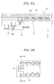
- FIG. 4A is a view illustrating a mechanism in which staples are shot from the cartridge 13.
- Drivers 17 formed of resin or the like are arranged under the staples 15A.
- a wedge 18 having an inclined surface 18A on a distal end side is arranged within the cartridge 13. If the second trigger 35 is operated to advance the wedge 18, the wedge 18 pushes up drivers 17 that have come into contact with the inclined surface 18A.
- the staples 15A are shot sequentially from the proximal end side by being pushed by the drivers 17 and pass through a tissue, and end portions of the staples passed through the tissue are pressed against and folded by the anvil member 21 provided at the second jaw 12.
- a driver 19 that pushes up the two first staple rows 15 and the second staples 16 are arranged in a region closer to the distal end side than the slot 14A. Accordingly, if the wedge 18 pushes up the driver 19, the staples 15A of the first staple rows 15 and the second staples 16 are pushed up and shot together.
- tissue ablation apparatus 1 the operation when the tissue ablation apparatus 1 is used will be described taking a case where all the layers of a malignant tumor (hereinafter simply referred to as a "tumor") of the stomach (lumen tissue) are ablated as an example.
- a malignant tumor hereinafter simply referred to as a "tumor”
- the stomach lumen tissue
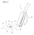
- a surgeon introduces the tissue ablation apparatus 1 into the stomach from a patient's mouth or the like, and observes the tumor, using the observation section 50. Then, as shown in FIG. 5 , a rough ablation region R surrounding a tumor Tm is set. It is preferable that the ablation region R be set so that the shortest distance from the tumor Tm becomes equal to or greater than 5 millimeters (mm) so as not to damage the tumor Tm at the time of tissue ablation.
- mm millimeters
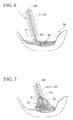
- the surgeon protrudes the treatment tool 100 for an endoscope from the first jaw 11, and as shown in FIG. 6 , grasps one point of a stomach wall apart from the tumor Tm, using the forceps portion 101, from the inside of the stomach Sm. Since this one point becomes a portion of a peripheral edge of a region to actually be ablated, it is preferable that this point be set to a position equivalent to a peripheral edge portion of the set ablation region R, for example, a part apart from the center of the tumor Tm by about 30 mm can be selected.
- this one grasped point is referred to as a first grasped point P1.
- the surgeon retracts the treatment tool 100 for an endoscope that has grasped the first grasped point P1, and as shown in FIG. 7 , pulls a portion of a stomach wall tissue ST into a gap between the first jaw 11 and the second jaw 12 while appropriately operating the first trigger 34.
- the tumor Tm is observed by the observation section 50, and attention is paid so that the tumor Tm is not touched by the pair of jaws.
- the stomach wall tissue ST is pulled in between the first jaw 11 and the second jaw 12 along two first pull-in lines L1 that extend from the first grasped point P1. That is, the pulled-in stomach wall tissue ST is folded with the external surface of the stomach turned inward so that the external surfaces of the stomach come into contact with each other, and is pulled in in a state where one pull-in line of the first pull-in lines L1 faces the first jaw 11 and the other pull-in line faces the second jaw 12. Since the gap between the pair of jaws is narrow slit-shaped and the spacing therebetween is a thickness equivalent to approximately two sheets of stomach wall tissues, tissues of other internal organs adjacent to the stomach are not pulled in between the pair of jaws together with the stomach wall tissues.
- stomach wall tissue ST is sufficiently pulled in between the pair of jaws 11 and 12, the surgeon operates the second trigger 35. Accordingly, the wedge 18 advances toward a distal end within the cartridge 13, and the drivers 17 arranged under the respective staples 15A of the first staple rows 15 are pushed up sequentially from the proximal end side. As a result, the staples 15A are pressed against the anvil member 21 (refer to FIG. 4A ) sequentially provided at the second jaw 12 from the proximal end side toward the distal end side, and both the end portions of the staples 15A passed through the stomach wall tissue ST are folded. As a result, the folded stomach wall tissue ST is fastened so as to become integral along the thickness direction on both sides of the first pull-in lines L1.
- the cutter 20 advances toward the distal end slightly later than the wedge 18, and cuts the stomach wall tissue located between the first staple rows 15 that has fastened the stomach wall tissue ST, substantially along the first pull-in lines L1.
- FIG. 8 a portion of the stomach wall is cut over all the layers.
- the stomach wall tissue located between the first staple rows 15 on the front on an extension line of a flow line (substantially the same as the slot 14A) of the cutter 20 is integrally fastened by the second staples 16.
- the surgeon extracts the tissue ablation apparatus 1 out of the body cavity, replaces the cartridge 13 with a new cartridge loaded with staples, and introduces the new cartridge again into the stomach. Then, as shown in FIG. 9 , the stomach wall tissue is grasped by the forceps portion 101 of the treatment tool 100 for an endoscope, with an end portion of a cutting line along the first pull-in lines L1 opposite to the first grasped point P1 as a second grasped point P2.
- the surgeon retracts the treatment tool 100 for an endoscope, and as shown in FIG. 10 , pulls the stomach wall tissue ST grasped by the forceps portion 101 into the pair of jaws 11 and 12 along second pull-in lines L2.
- the stomach wall tissue ST is pulled in so that a ridgeline rg of the stomach wall tissue that is folded so that the external surfaces of the stomach come into contact with each other passes through the inside of the pair of jaws 11 and 12.
- the stomach wall tissue ST is cut and fastened along the second pull-in lines L2. Moreover, since the first pull-in lines L1 and the second pull-in lines L2 form a closed quadrangle as shown in FIG. 5 , the stomach wall tissue ST within the ablation region R including the tumor Tm is cut and separated from the stomach Sm, as shown in FIG. 11 , by the cutting line formed along the first pull-in lines L1 and the second pull-in lines L2. In this way, a portion of the stomach wall tissue ST is ablated over all the layers without leaving a hole in the stomach Sm.
- the surgeon extracts the tissue ablation apparatus 1, collects the ablated stomach wall tissue ST (ablated piece), and completes the procedure.
- the ablated piece may be grasped by the forceps portion 101, and the extraction of the tissue ablation apparatus 1 and the collection of the ablated piece may be simultaneously performed.
- the related-art all-layer ablation has been performed through a laparotomy or laparoscopic surgery.
- this ablation is performed through natural openings, such as a mouth, from viewpoints of making invasion to a patient smaller or of reducing the risk of recurrence when a tumor is ablated.
- tissue ablation apparatus 1 of the present embodiment since the second staples 16 serving as the tissue sealing portion are arranged in the cartridge 13, a tissue between the first staple rows 15 ahead of the cutting line of the cutter 20 is reliably fastened and sealed by the second staples 16. Additionally, the holding using the pair of jaws is released after a tissue is first fastened by the first staple rows 15 and the second staples 16 and the cutting member cuts the tissue, in a state where the tissue is pulled into a narrow gap between the pair of jaws 11 and 12 and grasped by the jaws. Accordingly, tissue ablation can be performed in a series of procedures using the tissue ablation apparatus 1 without completely causing a state where there is a concern that the contents of the lumen tissue may leak out to the outside.
- suturing and cutting are performed after a tissue is pulled into a relatively narrow slit-shaped gap between the pair of closed jaws 11 and 12, even if other internal organs, tissues, or the like that are adjacent to a lumen tissue, such as the stomach, are likely to be pulled in together, this is prevented at an inlet of the gap. Accordingly, even in an approach through a natural opening where the outside of the lumen tissue cannot be visually recognized, the procedures can be performed without erroneously suturing or cutting these internal organs, tissues, or the like together with the lumen tissue.
- the structure for shooting the staples is not limited to this.
- the driver that pushes up the second staples may be separate from the drivers that push up the first staple rows.
- a structure may be adopted in which a second wedge 23 is provided ahead of the cutter 20 and a driver 22 that pushes up the second staples 16 is pushed up by the second wedge 23.
- a configuration may be adopted in which the common driver 19 is pushed up by the second wedge 23, or a structure may be adopted in which all the drivers are pushed up by the second wedge 23.
- the orientation of the staples of the first staple rows and the orientation of the second staples are parallel to each other.
- the longitudinal direction of second staples 16A may be arranged so as to be orthogonal to the slot 14A along which the cutter 20 moves.
- a difference between a tissue ablation apparatus 71 of the present embodiment and the tissue ablation apparatus 1 of the first embodiment is the configuration of a tissue anastomosis portion.
- components common to those already described will be designated by the same reference numerals, and duplicate description will be omitted.
- FIG. 15 is a partially enlarged view illustrating the distal end side of the first jaw 11 and a cartridge 72 in the tissue ablation apparatus 71.
- a linear or beltlike first electrode 73 is provided instead of the second staples ahead of the slot 14A.
- An insulator 74 is arranged around the first electrode 73 and is insulated from other metal regions in the treatment section 10.
- a second electrode 76 having the same structure as the first electrode 73 is provided at a position corresponding to the first electrode 73 in an anvil member 75 provided at the second jaw 12, and the first electrode 73 and the second electrode 76 are connected to a high-frequency power source 77. ON/OFF of energization can be switched by an operation section (not shown).
- the tissue ablation apparatus 71 When the tissue ablation apparatus 71 is used, similar to the first embodiment, a tissue is fastened and cut using the first staple rows 15 and the first cutter 20, and then, a high-frequency current is applied to the tissue sandwiched between the first electrode 73 and the second electrode 76 from the high-frequency power source 77 without opening the pair of jaws 11 and 12. Accordingly, the pair of electrodes including the first electrode 73 and the second electrode 76 function as a so-called bipolar electrosurgical instrument. As a result, as described in Japanese Unexamined Patent Application, First Publication No.
- intracellular components and extracelluar components of a tissue that is energized by coming into contact with the first electrode 73 and the second electrode 76 are homogenized (liquidized), tissues are joined together between the pair of jaws 11 and 12, and a hole formed due to the remaining of a non-fastened tissue is sealed.
- tissue ablation can be performed without completely causing a state where there is a concern that the contents of the lumen tissue may leak out to the outside.
- tissue sealing portion is constituted by the first electrode 73 and the second electrode 76, sealed regions are joined together in a planar fashion. As a result, the hole can be more reliably blocked.
- the configuration of the tissue sealing portion that seals a contacting tissue through energization is not limited to the above-described bipolar mechanism.
- a configuration may be adopted in which heat generating elements, such as heaters, which generate heat by energization, are attached to the cartridge and the anvil member instead of the first electrode 73 and the second electrode 76 and a tissue sandwiched between the pair of jaws is heated from both sides. Since these heat generating elements function as a so-called thermal coagulation treatment tool by virtue of this configuration, tissues can be joined together by appropriately setting temperature and heating time.
- the shape of the electrodes is not limited to the above-described linear shape, belt shape, or the like, and may be a spot shape as in an electrode 73A as shown in FIG. 17 .
- the number of times of suturing and cutting is not limited to twice.
- the ablation region may not be cut in two times depending on the size of the jaws.
- second suturing and cutting are performed in a state where a portion of a lumen tissue is pulled in so that the ridgeline of the folded lumen tissue does not pass through the inside of the slit, the tissue to be ablated is not cut and separated even after the second suturing and cutting.
- all layers of a region with an arbitrary size can be ablated by repeating the same suturing and cutting if necessary and finally by performing suturing and cutting such that the ridgeline of the lumen tissue passes through the inside of the slit.
- the related-art cartridge that does not have the tissue sealing portion may be used.
- the lumen tissue serving as a target of the tissue ablation apparatus of the present invention is not limited to the stomach.
- the diameter of the intestines is small compared to that of the stomach, the tissue ablation method of the present invention can be favorably performed even in the intestines by appropriately setting the size of the devices to be used, such as a stapler.
- the diseases of which tissues are to be ablated are also not limited to the tumor described in the embodiments, and for example, can be applied to other diseases, such as a serious ulcer.
- tissue sealing portion is arranged in the cartridge, a tissue between the pair of sealing portions ahead of the cutting line of the cutting member is reliably fastened and sealed by the tissue sealing portion. Additionally, the holding using the pair of grasping members is released after a tissue is first fastened by the pair of sealing portions and the tissue sealing portion and the cutting member cuts the tissue, in a state where the tissue is pulled into a narrow gap between the pair of grasping members and grasped by the grasping members. Accordingly, tissue ablation can be performed in a series of procedures using the tissue ablation apparatus without completely causing a state where there is a concern that the contents of the lumen tissue may leak out to the outside.
Landscapes
- Health & Medical Sciences (AREA)
- Surgery (AREA)
- Life Sciences & Earth Sciences (AREA)
- Engineering & Computer Science (AREA)
- Biomedical Technology (AREA)
- Nuclear Medicine, Radiotherapy & Molecular Imaging (AREA)
- Heart & Thoracic Surgery (AREA)
- Medical Informatics (AREA)
- Molecular Biology (AREA)
- Animal Behavior & Ethology (AREA)
- General Health & Medical Sciences (AREA)
- Public Health (AREA)
- Veterinary Medicine (AREA)
- Otolaryngology (AREA)
- Plasma & Fusion (AREA)
- Physics & Mathematics (AREA)
- Surgical Instruments (AREA)
Abstract
Description
- The present invention relates to a tissue ablation apparatus, and more particularly, a tissue ablation apparatus to be used for all-layer ablation that ablates a portion of a lumen tissue over an entire thickness direction.
- Priority is claimed on United States Patent Application No.
61/728,507 - In the related art, in the medical treatment of stomach cancer or the like, ablating a tumor and its surrounding tissue over an entire thickness direction of the stomach wall is performed. Such all-layer ablation is often performed by a laparotomy or laparoscopic surgery.
- Additionally, a stapler for operation equipped with a pair of jaws is described in Patent Document 1. One of the pair of jaws is mounted with a cartridge loaded with staples, and an anvil member that has a plurality of staple pockets is attached to the other jaw. If the jaws are closed with a tissue interposed between the pair of jaws, a portion of the tissue can be ablated over all the layers by a built-in cutter while suturing the tissue with staples.
- [Patent Document 1] Published Japanese Translation No.
2010-522035 - The related-art all-layer ablation has been performed through a laparotomy or laparoscopic surgery. However, it is studied that this ablation is performed through natural openings, such as a mouth, from viewpoints of making invasion to a patient smaller or of reducing the risk of recurrence when a tumor is ablated.
- However, in the related-art tissue ablation apparatus as described in Patent Document 1, only first staple rows are provided. Therefore, if suturing and cutting are performed along first pull-in lines, a tissue between the first staple rows on a distal end side of (ahead of) the cutting line of the cutting member is not fastened, and a region that becomes a hole-like state remains. Therefore, for example, when the internal pressure of the lumen tissue becomes high, there is a problem in that a state where there is a concern that the contents of the lumen tissue may leak out to the outside from the relevant region may occur, though the leak-out is temporary.
- A tissue ablation apparatus of a first aspect of the present invention includes a pair of grasping members that holds a tissue; and a cartridge that is replaceably attached to the pair of grasping members. The cartridge includes a cartridge body that has a longitudinal axis and a slot extending along the longitudinal axis, guides a cutting member cutting a tissue by the slot, and defines a movement range of the cutting member; a pair of sealing portions that are provided on both sides of the slot so as to sandwich the slot and extend parallel to the slot; and a tissue sealing portion that is provided closer to a distal end side than the slot and is provided on an extension line of the slot.
- According to the tissue ablation apparatus of a second aspect, in the first aspect, the tissue sealing portion may be held between the pair of grasping members, and may join the tissue located closer to the distal end side than the slot.
- According to the tissue ablation apparatus of a third aspect, in the first aspect, the pair of sealing portions may extend toward the distal end side than the slot, and the tissue sealing portion may be provided between the pair of sealing portions.
- According to the tissue ablation apparatus of a fourth aspect, in the first aspect, the pair of sealing portions may be a pair of staple rows configured by a plurality of staples arranged within the cartridge body.
- According to the tissue ablation apparatus of a fifth aspect, in the first aspect, the tissue sealing portion may be a sealing staple arranged on the distal end side of the slot within the cartridge body.
- According to the tissue ablation apparatus of a sixth aspect, in the first aspect, the tissue sealing portion may be a pair of electrodes that are held between the pair of grasping members and are capable of coming into contact with the tissue located closer to the distal end side than the slot.
- According to the tissue ablation apparatus of a seventh aspect, in the first aspect, the tissue sealing portion may be a pair of heat generating elements that are held between the pair of grasping members and are capable of coming into contact with the tissue located closer to the distal end side than the slot.
- A tissue ablation apparatus of an eighth aspect of the present invention includes an insertion section that extends along a longitudinal axis; a pair of grasping members that are provided at a distal end of the insertion section and grasp a tissue; a cutting member that moves along a predetermined flow line to thereby cut a lumen tissue held between the pair of jaws; a pair of sealing portions that are provided on both sides of the flow line so as to sandwich the flow line and extend parallel to the flow line; and a tissue sealing portion that is provided on an extension line of the flow line ahead of the flow line.
- According to the tissue ablation apparatus of a ninth aspect, in the eighth aspect, the tissue sealing portion may be held between the pair of grasping members, and may join the tissue located closer to the distal end side than the flow line.
- According to the tissue ablation apparatus of a tenth aspect, in the eighth aspect, the pair of sealing portions may extend toward the distal end side than the flow line, and the tissue sealing portion may be provided between the pair of sealing portions.
- According to the tissue ablation apparatus of an eleventh aspect, in the eighth aspect, the pair of sealing portions may be a pair of staple rows configured by a plurality of staples arranged on both sides of the flow line.
- According to the tissue ablation apparatus of a twelfth aspect, in the eighth aspect, the tissue sealing portion may be a sealing staple arranged on the distal end side of the flow line.
- According to the tissue ablation apparatus of a thirteenth aspect, in the eighth aspect, the tissue sealing portion may be a pair of electrodes that are held between the pair of grasping members and are capable of coming into contact with the tissue located closer to the distal end side than the flow line.
- According to the tissue ablation apparatus of a fourteenth aspect, in the eighth aspect, the tissue sealing portion may be a pair of heat generating elements that are held between the pair of grasping members and are capable of coming into contact with the tissue located closer to the distal end side than the flow line.
- In the tissue ablation apparatuses of the above respective aspects, since the tissue sealing portion is arranged in the cartridge, a tissue between the pair of sealing portions on the distal end side of (ahead of) the cutting line of the cutting member is reliably fastened and sealed by the tissue sealing portion. Additionally, the holding using the pair of grasping members is released after a tissue is first fastened by the pair of sealing portions and the tissue sealing portion and the cutting member cuts the tissue, in a state where the tissue is pulled into a narrow gap between the pair of grasping members and grasped by the grasping members. Accordingly, tissue ablation can be performed in a series of procedures using the tissue ablation apparatus without completely causing a state where there is a concern that the contents of the lumen tissue may leak out to the outside.
-
-
FIG. 1 is a view illustrating an overall configuration of a tissue ablation apparatus of a first embodiment of the present invention. -
FIG. 2 is a view illustrating one operation when the tissue ablation apparatus is used. -
FIG. 3 is a partially enlarged view illustrating a state where a first jaw and a cartridge of the tissue ablation apparatus are viewed from a second jaw side. -
FIG. 4A is a view illustrating a mechanism in which staples are shot from the cartridge. -
FIG. 4B is a view illustrating drivers within the cartridge. -
FIG. 5 is a view illustrating an ablation region and a grasped point. -
FIG. 6 is a view illustrating one operation when the tissue ablation apparatus is used. -
FIG. 7 is a view illustrating one operation when the tissue ablation apparatus is used. -
FIG. 8 is a view illustrating one operation when the tissue ablation apparatus is used. -
FIG. 9 is a view illustrating one operation when the tissue ablation apparatus is used. -
FIG. 10 is a view illustrating one operation when the tissue ablation apparatus is used. -
FIG. 11 is a view illustrating one operation when the tissue ablation apparatus is used. -
FIG. 12 is a view illustrating a state after suturing and cutting is performed using a related-art tissue ablation apparatus. -
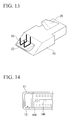
FIG. 13 is a view illustrating a cutter in a modification example of the embodiment. -
FIG. 14 is a partially enlarged view illustrating a distal end side of the first jaw and a cartridge in the modification example of the embodiment. -
FIG. 15 is a partially enlarged view illustrating a distal end side of a first jaw and a cartridge in a tissue ablation apparatus of a second embodiment of the present invention. -
FIG. 16 is a view illustrating electrical connection in the tissue ablation apparatus. -
FIG. 17 is a partially enlarged view illustrating a distal end side of a first jaw and a cartridge in a modification example of the embodiment. - Hereinafter, a first embodiment of the present invention will be described with reference to
FIGS. 1 to 14 . -
FIG. 1 is a view illustrating an overall configuration of a tissue ablation apparatus 1 of the present embodiment. The tissue ablation apparatus 1 includes atreatment section 10 that is provided at a distal end to perform a treatment on a target tissue. Additionally, the tissue ablation apparatus 1 includes afirst operation section 30 for operating thetreatment section 10, anelongated insertion section 40 provided between thetreatment section 10 and thefirst operation section 30, anobservation section 50 inserted through theinsertion section 40, asecond operation section 60 for operating theobservation section 50, and athird operation section 70 for operating the treatment section. Thetreatment section 10 has a first jaw (first grasping member) 11 and a second jaw (second grasping member) 12 as a pair of openable and closable jaws, and sutures and detaches a tissue, using acartridge 13 loaded withstaples 13A. Additionally, the basic structure of thetreatment section 10 is well-known, for example, as described in Patent Document 1. - The
first operation section 30 has a well-known configuration and has twodial knobs third operation section 70 is provided with afirst trigger 34 for operating the opening and closing of the pair ofjaws second trigger 35 for performing suture and incision operations. - The
insertion section 40 has flexibility and is formed in a tubular shape that extends along a longitudinal axis. Thetreatment section 10 is attached to a distal end side of theinsertion section 40, and thefirst operation section 30 is attached to a proximal end side of theinsertion section 40. Theinsertion section 40 has the bendingportion 41 of a well-known structure having a plurality of joint rings, bending pieces, or the like on the distal end side thereof, and can be bent by operating the dial knobs 31 and 32 of thefirst operation section 30. The bent state can be fixed by operating the lockinglever 33. The operating member is inserted through an inner cavity of theinsertion section 40 so as to be able to advance and retract in an axial direction. Additionally, aforceps port 42 is provided on the proximal end side of theinsertion section 40, and ageneral treatment tool 100 or the like for an endoscope equipped with aforceps portion 101 can be inserted into theforceps port 42 and can be protruded from the proximal end side of thefirst jaw 11. - The
observation section 50 is inserted through theinsertion section 40 so as to be able to advance and retract, and includes anillumination unit 51 including an LED or the like and imaging means 52, such as a CCD, at a distal end portion thereof. Additionally, the observation section has a bendingportion 53 having the same structure as the bendingportion 41 on the distal end side thereof. A distal end portion of theobservation section 50 can be protruded and retracted from anopening 43 provided on the distal end side of theinsertion section 40. Accordingly, for example, as shown inFIG. 2 , a tissue held by thetreatment section 10 can be favorably observed by protruding the distal end portion of theobservation section 50 and appropriately bending the bendingportion 53. - The
second operation section 60 is connected to a proximal end of theobservation section 50 that comes out of the proximal end side of theinsertion section 40. Thesecond operation section 60 is provided with thesame dial knob 61,button 62, or the like as those of thefirst operation section 30. Thesecond operation section 60 can perform the bending operation of the bendingportion 53, the operation of theillumination unit 51 and the imaging means 52, or the like. A video signal acquired by the imaging means 52 is sent to an image processor (not shown) through auniversal cable 63, and is displayed on a display (not shown) or the like. As theobservation section 50 and thesecond operation section 60, a well-known endoscope apparatus or the like can be used by appropriately setting dimensions or the like. -
FIG. 3 is a partially enlarged view illustrating a state where thefirst jaw 11 and thecartridge 13 are viewed from thesecond jaw 12 side. Thecartridge 13 includes acartridge body 14 having a longitudinal axis and aslot 14A extending along the longitudinal axis for allowing a cutter (cutting member) 20 that cuts a tissue to move therealong, a pair of first staple rows (a pair of sealing portions) 15 that extends parallel to theslot 14A on both sides of theslot 14A in a width direction, respectively, and second staples (tissue sealing portion, sealing staples) 16 arranged on an extension line of theslot 14A ahead of (closer to the distal end side than theslot 14A) of theslot 14A. - A plurality of
staples 15A are aligned and arranged within thecartridge body 14 in the firststaple row 15, and extend further toward the distal end side than theslot 14A by a predetermined length, for example, 5 millimeters (mm). Thesecond staples 16 are arranged between the twofirst staple rows 15. AlthoughFIG. 3 shows an example in which twosecond staples 16 are arranged, the number of second staples to be arranged is not particularly limited, and may be one or may be three or more. The staples to be arranged as the second staples may be thesame staples 15A as the first staple rows, and may be different therefrom. - The
cutter 20 is inserted through theslot 14A from the inside of thecartridge 13, and moves within theslot 14A in a state where the cutter has protruded toward thesecond jaw 12. Thecutter 20 moves along theslot 14A in a state where a protruding end of thecutter 20 has entered a groove provided in an anvil member to be described below so that a tissue sandwiched between the pair ofjaws cutter 20 required for this is greater than a thickness equivalent to two sheets of target tissues held in a folded state and is greater than the distance between the pair ofjaws -
FIG. 4A is a view illustrating a mechanism in which staples are shot from thecartridge 13.Drivers 17 formed of resin or the like are arranged under thestaples 15A. Awedge 18 having aninclined surface 18A on a distal end side is arranged within thecartridge 13. If thesecond trigger 35 is operated to advance thewedge 18, thewedge 18 pushes updrivers 17 that have come into contact with theinclined surface 18A. As a result, thestaples 15A are shot sequentially from the proximal end side by being pushed by thedrivers 17 and pass through a tissue, and end portions of the staples passed through the tissue are pressed against and folded by theanvil member 21 provided at thesecond jaw 12. - Although the
drivers 17 are respectively arranged at the twofirst staple rows 15, as shown inFIG. 4B , adriver 19 that pushes up the twofirst staple rows 15 and thesecond staples 16 are arranged in a region closer to the distal end side than theslot 14A. Accordingly, if thewedge 18 pushes up thedriver 19, thestaples 15A of thefirst staple rows 15 and thesecond staples 16 are pushed up and shot together. - Next, the operation when the tissue ablation apparatus 1 is used will be described taking a case where all the layers of a malignant tumor (hereinafter simply referred to as a "tumor") of the stomach (lumen tissue) are ablated as an example.
- First, a surgeon introduces the tissue ablation apparatus 1 into the stomach from a patient's mouth or the like, and observes the tumor, using the
observation section 50. Then, as shown inFIG. 5 , a rough ablation region R surrounding a tumor Tm is set. It is preferable that the ablation region R be set so that the shortest distance from the tumor Tm becomes equal to or greater than 5 millimeters (mm) so as not to damage the tumor Tm at the time of tissue ablation. - Next, the surgeon protrudes the
treatment tool 100 for an endoscope from thefirst jaw 11, and as shown inFIG. 6 , grasps one point of a stomach wall apart from the tumor Tm, using theforceps portion 101, from the inside of the stomach Sm. Since this one point becomes a portion of a peripheral edge of a region to actually be ablated, it is preferable that this point be set to a position equivalent to a peripheral edge portion of the set ablation region R, for example, a part apart from the center of the tumor Tm by about 30 mm can be selected. Hereinafter, this one grasped point is referred to as a first grasped point P1. - Subsequently, the surgeon retracts the
treatment tool 100 for an endoscope that has grasped the first grasped point P1, and as shown inFIG. 7 , pulls a portion of a stomach wall tissue ST into a gap between thefirst jaw 11 and thesecond jaw 12 while appropriately operating thefirst trigger 34. During the pull-in, the tumor Tm is observed by theobservation section 50, and attention is paid so that the tumor Tm is not touched by the pair of jaws. - The stomach wall tissue ST is pulled in between the
first jaw 11 and thesecond jaw 12 along two first pull-in lines L1 that extend from the first grasped point P1. That is, the pulled-in stomach wall tissue ST is folded with the external surface of the stomach turned inward so that the external surfaces of the stomach come into contact with each other, and is pulled in in a state where one pull-in line of the first pull-in lines L1 faces thefirst jaw 11 and the other pull-in line faces thesecond jaw 12. Since the gap between the pair of jaws is narrow slit-shaped and the spacing therebetween is a thickness equivalent to approximately two sheets of stomach wall tissues, tissues of other internal organs adjacent to the stomach are not pulled in between the pair of jaws together with the stomach wall tissues. - If the stomach wall tissue ST is sufficiently pulled in between the pair of
jaws second trigger 35. Accordingly, thewedge 18 advances toward a distal end within thecartridge 13, and thedrivers 17 arranged under therespective staples 15A of thefirst staple rows 15 are pushed up sequentially from the proximal end side. As a result, thestaples 15A are pressed against the anvil member 21 (refer toFIG. 4A ) sequentially provided at thesecond jaw 12 from the proximal end side toward the distal end side, and both the end portions of thestaples 15A passed through the stomach wall tissue ST are folded. As a result, the folded stomach wall tissue ST is fastened so as to become integral along the thickness direction on both sides of the first pull-in lines L1. - Moreover, the cutter 20 (refer to
FIG. 4A ) advances toward the distal end slightly later than thewedge 18, and cuts the stomach wall tissue located between thefirst staple rows 15 that has fastened the stomach wall tissue ST, substantially along the first pull-in lines L1. As a result, as shown inFIG. 8 , a portion of the stomach wall is cut over all the layers. Here, the stomach wall tissue located between thefirst staple rows 15 on the front on an extension line of a flow line (substantially the same as theslot 14A) of thecutter 20 is integrally fastened by thesecond staples 16. - After the cutting and suturing along the first pull-in lines L1 are completed, the surgeon extracts the tissue ablation apparatus 1 out of the body cavity, replaces the
cartridge 13 with a new cartridge loaded with staples, and introduces the new cartridge again into the stomach. Then, as shown inFIG. 9 , the stomach wall tissue is grasped by theforceps portion 101 of thetreatment tool 100 for an endoscope, with an end portion of a cutting line along the first pull-in lines L1 opposite to the first grasped point P1 as a second grasped point P2. - Next, the surgeon retracts the
treatment tool 100 for an endoscope, and as shown inFIG. 10 , pulls the stomach wall tissue ST grasped by theforceps portion 101 into the pair ofjaws jaws - Thereafter, if suturing and cutting are performed by the same operation as the above-described operation, the stomach wall tissue ST is cut and fastened along the second pull-in lines L2. Moreover, since the first pull-in lines L1 and the second pull-in lines L2 form a closed quadrangle as shown in
FIG. 5 , the stomach wall tissue ST within the ablation region R including the tumor Tm is cut and separated from the stomach Sm, as shown inFIG. 11 , by the cutting line formed along the first pull-in lines L1 and the second pull-in lines L2. In this way, a portion of the stomach wall tissue ST is ablated over all the layers without leaving a hole in the stomach Sm. - After the completion of the ablation, the surgeon extracts the tissue ablation apparatus 1, collects the ablated stomach wall tissue ST (ablated piece), and completes the procedure. In this case, the ablated piece may be grasped by the
forceps portion 101, and the extraction of the tissue ablation apparatus 1 and the collection of the ablated piece may be simultaneously performed. - As described at the beginning, the related-art all-layer ablation has been performed through a laparotomy or laparoscopic surgery. However, it is studied that this ablation is performed through natural openings, such as a mouth, from viewpoints of making invasion to a patient smaller or of reducing the risk of recurrence when a tumor is ablated.
- However, in the related-art tissue ablation apparatus described in the above Patent Document 1, only the first staple rows are provided. Therefore, if suturing and cutting are performed along the first pull-in lines, as shown in
FIG. 12 , a tissue between the first staple rows ahead of the cutting line of the cutter is not fastened, and a region that becomes a hole-like state remains. Therefore, for example, when the internal pressure of the lumen tissue becomes high, there is a problem in that a state where there is a concern that the contents of the lumen tissue may leak out to the outside from the relevant region may occur. - According to the tissue ablation apparatus 1 of the present embodiment, since the
second staples 16 serving as the tissue sealing portion are arranged in thecartridge 13, a tissue between thefirst staple rows 15 ahead of the cutting line of thecutter 20 is reliably fastened and sealed by thesecond staples 16. Additionally, the holding using the pair of jaws is released after a tissue is first fastened by thefirst staple rows 15 and thesecond staples 16 and the cutting member cuts the tissue, in a state where the tissue is pulled into a narrow gap between the pair ofjaws - Additionally, since suturing and cutting are performed after a tissue is pulled into a relatively narrow slit-shaped gap between the pair of
closed jaws - Although an example in which the staples of the first staple rows and the second staples are shot by the common driver closer to the distal end side than the
slot 14A has been described in the present embodiment, the structure for shooting the staples is not limited to this. For example, the driver that pushes up the second staples may be separate from the drivers that push up the first staple rows. Specifically, as shown inFIG. 13 , a structure may be adopted in which asecond wedge 23 is provided ahead of thecutter 20 and adriver 22 that pushes up thesecond staples 16 is pushed up by thesecond wedge 23. Otherwise, a configuration may be adopted in which thecommon driver 19 is pushed up by thesecond wedge 23, or a structure may be adopted in which all the drivers are pushed up by thesecond wedge 23. - Additionally, in the above-described example, the orientation of the staples of the first staple rows and the orientation of the second staples are parallel to each other. However, as in a modification example shown in
FIG. 14 , the longitudinal direction ofsecond staples 16A may be arranged so as to be orthogonal to theslot 14A along which thecutter 20 moves. By adopting such a configuration, tissues ahead of the slot can be joined within a wider range, and tissue ablation can be more reliably performed. - Next, a second embodiment of the present invention will be described. A difference between a
tissue ablation apparatus 71 of the present embodiment and the tissue ablation apparatus 1 of the first embodiment is the configuration of a tissue anastomosis portion. In addition, in the following description, components common to those already described will be designated by the same reference numerals, and duplicate description will be omitted. -
FIG. 15 is a partially enlarged view illustrating the distal end side of thefirst jaw 11 and acartridge 72 in thetissue ablation apparatus 71. A linear or beltlikefirst electrode 73 is provided instead of the second staples ahead of theslot 14A. Aninsulator 74 is arranged around thefirst electrode 73 and is insulated from other metal regions in thetreatment section 10. - As shown in
FIG. 16 , asecond electrode 76 having the same structure as thefirst electrode 73 is provided at a position corresponding to thefirst electrode 73 in an anvil member 75 provided at thesecond jaw 12, and thefirst electrode 73 and thesecond electrode 76 are connected to a high-frequency power source 77. ON/OFF of energization can be switched by an operation section (not shown). - When the
tissue ablation apparatus 71 is used, similar to the first embodiment, a tissue is fastened and cut using thefirst staple rows 15 and thefirst cutter 20, and then, a high-frequency current is applied to the tissue sandwiched between thefirst electrode 73 and thesecond electrode 76 from the high-frequency power source 77 without opening the pair ofjaws first electrode 73 and thesecond electrode 76 function as a so-called bipolar electrosurgical instrument. As a result, as described in Japanese Unexamined Patent Application, First Publication No.2009-247893 first electrode 73 and thesecond electrode 76 are homogenized (liquidized), tissues are joined together between the pair ofjaws - Even in the
tissue ablation apparatus 71 of the present embodiment, similar to the first embodiment, tissue ablation can be performed without completely causing a state where there is a concern that the contents of the lumen tissue may leak out to the outside. - Additionally, since a tissue sealing portion is constituted by the
first electrode 73 and thesecond electrode 76, sealed regions are joined together in a planar fashion. As a result, the hole can be more reliably blocked. - In the present embodiment, the configuration of the tissue sealing portion that seals a contacting tissue through energization is not limited to the above-described bipolar mechanism. For example, a configuration may be adopted in which heat generating elements, such as heaters, which generate heat by energization, are attached to the cartridge and the anvil member instead of the
first electrode 73 and thesecond electrode 76 and a tissue sandwiched between the pair of jaws is heated from both sides. Since these heat generating elements function as a so-called thermal coagulation treatment tool by virtue of this configuration, tissues can be joined together by appropriately setting temperature and heating time. - Additionally, the shape of the electrodes is not limited to the above-described linear shape, belt shape, or the like, and may be a spot shape as in an
electrode 73A as shown inFIG. 17 . - While the respective embodiments of the present invention have been described above, the technical scope of the present invention is not limited to the above embodiments. Combinations of constituent elements can be changed, various alternations can be added to the respective constituent elements, or omissions can be made, without departing from the concept of the present invention.
- For example, although an example in which suturing and cutting are performed twice and a tissue is ablated has been described in the above embodiments, the number of times of suturing and cutting is not limited to twice. For example, in a case where a large ablation region is set due to a large tumor or the like, the ablation region may not be cut in two times depending on the size of the jaws. In such a case, if second suturing and cutting are performed in a state where a portion of a lumen tissue is pulled in so that the ridgeline of the folded lumen tissue does not pass through the inside of the slit, the tissue to be ablated is not cut and separated even after the second suturing and cutting. Thereafter, all layers of a region with an arbitrary size can be ablated by repeating the same suturing and cutting if necessary and finally by performing suturing and cutting such that the ridgeline of the lumen tissue passes through the inside of the slit. Here, since a tissue is not present ahead of the slot in the final suturing and cutting to ablate a tissue piece, the related-art cartridge that does not have the tissue sealing portion may be used.
- In addition, the lumen tissue serving as a target of the tissue ablation apparatus of the present invention is not limited to the stomach. For example, although the diameter of the intestines is small compared to that of the stomach, the tissue ablation method of the present invention can be favorably performed even in the intestines by appropriately setting the size of the devices to be used, such as a stapler.
- Additionally, it is natural that the diseases of which tissues are to be ablated are also not limited to the tumor described in the embodiments, and for example, can be applied to other diseases, such as a serious ulcer.
- According to the above respective embodiments, since the tissue sealing portion is arranged in the cartridge, a tissue between the pair of sealing portions ahead of the cutting line of the cutting member is reliably fastened and sealed by the tissue sealing portion. Additionally, the holding using the pair of grasping members is released after a tissue is first fastened by the pair of sealing portions and the tissue sealing portion and the cutting member cuts the tissue, in a state where the tissue is pulled into a narrow gap between the pair of grasping members and grasped by the grasping members. Accordingly, tissue ablation can be performed in a series of procedures using the tissue ablation apparatus without completely causing a state where there is a concern that the contents of the lumen tissue may leak out to the outside.
-
- 1,71: TISSUE ABLATION APPARATUS
- 11: FIRST JAW (FIRST GRASPING MEMBER)
- 12: SECOND JAW (SECOND GRASPING MEMBER) 14: CARTRIDGE BODY
- 14A: SLOT
- 15: PAIR OF FIRST STAPLE ROWS (PAIR OF SEALING PORTIONS)
- 16: SECOND STAPLE (TISSUE SEALING PORTION, SEALING STAPLE)
- 20: CUTTER (CUTTING MEMBER)
Claims (14)
- A tissue ablation apparatus comprising:a pair of grasping members which holds a tissue; anda cartridge which is replaceably attached to the pair of grasping members,wherein the cartridge includes:a cartridge body that has a longitudinal axis and a slot extending along the longitudinal axis, guides a cutting member cutting a tissue by the slot, and defines a movement range of the cutting member;a pair of sealing portions that are provided on both sides of the slot so as to sandwich the slot and extend parallel to the slot; anda tissue sealing portion that is provided closer to a distal end side than the slot and is provided on an extension line of the slot.
- The tissue ablation apparatus according to Claim 1,
wherein the tissue sealing portion is held between the pair of grasping members, and joins the tissue located closer to the distal end side than the slot. - The tissue ablation apparatus according to Claim 1,
wherein the pair of sealing portions extend toward the distal end side than the slot, and
wherein the tissue sealing portion is provided between the pair of sealing portions. - The tissue ablation apparatus according to Claim 1,
wherein the pair of sealing portions are a pair of staple rows configured by a plurality of staples arranged within the cartridge body. - The tissue ablation apparatus according to Claim 1,
wherein the tissue sealing portion is a sealing staple arranged on the distal end side of the slot within the cartridge body. - The tissue ablation apparatus according to Claim 1,
wherein the tissue sealing portion is a pair of electrodes that are held between the pair of grasping members and are capable of coming into contact with the tissue located closer to the distal end side than the slot. - The tissue ablation apparatus according to Claim 1,
wherein the tissue sealing portion is a pair of heat generating elements that are held between the pair of grasping members and are capable of coming into contact with the tissue located closer to the distal end side than the slot. - A tissue ablation apparatus comprising:an insertion section that extends along a longitudinal axis;a pair of grasping members that are provided at a distal end of the insertion section and grasp a tissue;a cutting member that moves along a predetermined flow line to thereby cut a lumen tissue held between the pair of jaws;a pair of sealing portions that are provided on both sides of the flow line so as to sandwich the flow line and extend parallel to the flow line; anda tissue sealing portion that is provided on an extension line of the flow line ahead of the flow line.
- The tissue ablation apparatus according to Claim 8,
wherein the tissue sealing portion is held between the pair of grasping members, and joins the tissue located closer to the distal end side than the flow line. - The tissue ablation apparatus according to Claim 8,
wherein the pair of sealing portions extend toward the distal end side than the flow line, and
wherein the tissue sealing portion is provided between the pair of sealing portions. - The tissue ablation apparatus according to Claim 8,
wherein the pair of sealing portions are a pair of staple rows configured by a plurality of staples arranged on both sides of the flow line. - The tissue ablation apparatus according to Claim 8,
wherein the tissue sealing portion is a sealing staple arranged on the distal end side of the flow line. - The tissue ablation apparatus according to Claim 8,
wherein the tissue sealing portion is a pair of electrodes that are held between the pair of grasping members and are capable of coming into contact with the tissue located closer to the distal end side than the flow line. - The tissue ablation apparatus according to Claim 8,
wherein the tissue sealing portion is a pair of heat generating elements that are held between the pair of grasping members and are capable of coming into contact with the tissue located closer to the distal end side than the flow line.
Applications Claiming Priority (2)
| Application Number | Priority Date | Filing Date | Title |
|---|---|---|---|
| US201261728507P | 2012-11-20 | 2012-11-20 | |
| PCT/JP2013/081020 WO2014080862A1 (en) | 2012-11-20 | 2013-11-18 | Tissue ablation apparatus |
Publications (2)
| Publication Number | Publication Date |
|---|---|
| EP2923656A1 true EP2923656A1 (en) | 2015-09-30 |
| EP2923656A4 EP2923656A4 (en) | 2016-07-13 |
Family
ID=50776045
Family Applications (1)
| Application Number | Title | Priority Date | Filing Date |
|---|---|---|---|
| EP13856141.0A Withdrawn EP2923656A4 (en) | 2012-11-20 | 2013-11-18 | Tissue ablation apparatus |
Country Status (5)
| Country | Link |
|---|---|
| US (1) | US20150150620A1 (en) |
| EP (1) | EP2923656A4 (en) |
| JP (1) | JP5608837B1 (en) |
| CN (1) | CN104334097B (en) |
| WO (1) | WO2014080862A1 (en) |
Families Citing this family (468)
| Publication number | Priority date | Publication date | Assignee | Title |
|---|---|---|---|---|
| US20070084897A1 (en) | 2003-05-20 | 2007-04-19 | Shelton Frederick E Iv | Articulating surgical stapling instrument incorporating a two-piece e-beam firing mechanism |
| US9060770B2 (en) | 2003-05-20 | 2015-06-23 | Ethicon Endo-Surgery, Inc. | Robotically-driven surgical instrument with E-beam driver |
| US11890012B2 (en) | 2004-07-28 | 2024-02-06 | Cilag Gmbh International | Staple cartridge comprising cartridge body and attached support |
| US11998198B2 (en) | 2004-07-28 | 2024-06-04 | Cilag Gmbh International | Surgical stapling instrument incorporating a two-piece E-beam firing mechanism |
| US9072535B2 (en) | 2011-05-27 | 2015-07-07 | Ethicon Endo-Surgery, Inc. | Surgical stapling instruments with rotatable staple deployment arrangements |
| US8215531B2 (en) | 2004-07-28 | 2012-07-10 | Ethicon Endo-Surgery, Inc. | Surgical stapling instrument having a medical substance dispenser |
| US11484312B2 (en) | 2005-08-31 | 2022-11-01 | Cilag Gmbh International | Staple cartridge comprising a staple driver arrangement |
| US7669746B2 (en) | 2005-08-31 | 2010-03-02 | Ethicon Endo-Surgery, Inc. | Staple cartridges for forming staples having differing formed staple heights |
| US10159482B2 (en) | 2005-08-31 | 2018-12-25 | Ethicon Llc | Fastener cartridge assembly comprising a fixed anvil and different staple heights |
| US7934630B2 (en) | 2005-08-31 | 2011-05-03 | Ethicon Endo-Surgery, Inc. | Staple cartridges for forming staples having differing formed staple heights |
| US11246590B2 (en) | 2005-08-31 | 2022-02-15 | Cilag Gmbh International | Staple cartridge including staple drivers having different unfired heights |
| US9237891B2 (en) | 2005-08-31 | 2016-01-19 | Ethicon Endo-Surgery, Inc. | Robotically-controlled surgical stapling devices that produce formed staples having different lengths |
| US20070106317A1 (en) | 2005-11-09 | 2007-05-10 | Shelton Frederick E Iv | Hydraulically and electrically actuated articulation joints for surgical instruments |
| US20110024477A1 (en) | 2009-02-06 | 2011-02-03 | Hall Steven G | Driven Surgical Stapler Improvements |
| US11793518B2 (en) | 2006-01-31 | 2023-10-24 | Cilag Gmbh International | Powered surgical instruments with firing system lockout arrangements |
| US11278279B2 (en) | 2006-01-31 | 2022-03-22 | Cilag Gmbh International | Surgical instrument assembly |
| US8820603B2 (en) | 2006-01-31 | 2014-09-02 | Ethicon Endo-Surgery, Inc. | Accessing data stored in a memory of a surgical instrument |
| US20110290856A1 (en) | 2006-01-31 | 2011-12-01 | Ethicon Endo-Surgery, Inc. | Robotically-controlled surgical instrument with force-feedback capabilities |
| US11224427B2 (en) | 2006-01-31 | 2022-01-18 | Cilag Gmbh International | Surgical stapling system including a console and retraction assembly |
| US20120292367A1 (en) | 2006-01-31 | 2012-11-22 | Ethicon Endo-Surgery, Inc. | Robotically-controlled end effector |
| US7753904B2 (en) | 2006-01-31 | 2010-07-13 | Ethicon Endo-Surgery, Inc. | Endoscopic surgical instrument with a handle that can articulate with respect to the shaft |
| US8186555B2 (en) | 2006-01-31 | 2012-05-29 | Ethicon Endo-Surgery, Inc. | Motor-driven surgical cutting and fastening instrument with mechanical closure system |
| US8708213B2 (en) | 2006-01-31 | 2014-04-29 | Ethicon Endo-Surgery, Inc. | Surgical instrument having a feedback system |
| US7845537B2 (en) | 2006-01-31 | 2010-12-07 | Ethicon Endo-Surgery, Inc. | Surgical instrument having recording capabilities |
| US8992422B2 (en) | 2006-03-23 | 2015-03-31 | Ethicon Endo-Surgery, Inc. | Robotically-controlled endoscopic accessory channel |
| US8322455B2 (en) | 2006-06-27 | 2012-12-04 | Ethicon Endo-Surgery, Inc. | Manually driven surgical cutting and fastening instrument |
| US10568652B2 (en) | 2006-09-29 | 2020-02-25 | Ethicon Llc | Surgical staples having attached drivers of different heights and stapling instruments for deploying the same |
| US8485412B2 (en) | 2006-09-29 | 2013-07-16 | Ethicon Endo-Surgery, Inc. | Surgical staples having attached drivers and stapling instruments for deploying the same |
| US11980366B2 (en) | 2006-10-03 | 2024-05-14 | Cilag Gmbh International | Surgical instrument |
| US8632535B2 (en) | 2007-01-10 | 2014-01-21 | Ethicon Endo-Surgery, Inc. | Interlock and surgical instrument including same |
| US8652120B2 (en) | 2007-01-10 | 2014-02-18 | Ethicon Endo-Surgery, Inc. | Surgical instrument with wireless communication between control unit and sensor transponders |
| US8684253B2 (en) | 2007-01-10 | 2014-04-01 | Ethicon Endo-Surgery, Inc. | Surgical instrument with wireless communication between a control unit of a robotic system and remote sensor |
| US11291441B2 (en) | 2007-01-10 | 2022-04-05 | Cilag Gmbh International | Surgical instrument with wireless communication between control unit and remote sensor |
| US11039836B2 (en) | 2007-01-11 | 2021-06-22 | Cilag Gmbh International | Staple cartridge for use with a surgical stapling instrument |
| US20080169332A1 (en) | 2007-01-11 | 2008-07-17 | Shelton Frederick E | Surgical stapling device with a curved cutting member |
| US8727197B2 (en) | 2007-03-15 | 2014-05-20 | Ethicon Endo-Surgery, Inc. | Staple cartridge cavity configuration with cooperative surgical staple |
| US8893946B2 (en) | 2007-03-28 | 2014-11-25 | Ethicon Endo-Surgery, Inc. | Laparoscopic tissue thickness and clamp load measuring devices |
| US8931682B2 (en) | 2007-06-04 | 2015-01-13 | Ethicon Endo-Surgery, Inc. | Robotically-controlled shaft based rotary drive systems for surgical instruments |
| US11857181B2 (en) | 2007-06-04 | 2024-01-02 | Cilag Gmbh International | Robotically-controlled shaft based rotary drive systems for surgical instruments |
| US7753245B2 (en) | 2007-06-22 | 2010-07-13 | Ethicon Endo-Surgery, Inc. | Surgical stapling instruments |
| US11849941B2 (en) | 2007-06-29 | 2023-12-26 | Cilag Gmbh International | Staple cartridge having staple cavities extending at a transverse angle relative to a longitudinal cartridge axis |
| RU2493788C2 (en) | 2008-02-14 | 2013-09-27 | Этикон Эндо-Серджери, Инк. | Surgical cutting and fixing instrument, which has radio-frequency electrodes |
| US8758391B2 (en) | 2008-02-14 | 2014-06-24 | Ethicon Endo-Surgery, Inc. | Interchangeable tools for surgical instruments |
| US7866527B2 (en) | 2008-02-14 | 2011-01-11 | Ethicon Endo-Surgery, Inc. | Surgical stapling apparatus with interlockable firing system |
| US7819298B2 (en) | 2008-02-14 | 2010-10-26 | Ethicon Endo-Surgery, Inc. | Surgical stapling apparatus with control features operable with one hand |
| US8573465B2 (en) | 2008-02-14 | 2013-11-05 | Ethicon Endo-Surgery, Inc. | Robotically-controlled surgical end effector system with rotary actuated closure systems |
| US9179912B2 (en) | 2008-02-14 | 2015-11-10 | Ethicon Endo-Surgery, Inc. | Robotically-controlled motorized surgical cutting and fastening instrument |
| US11986183B2 (en) | 2008-02-14 | 2024-05-21 | Cilag Gmbh International | Surgical cutting and fastening instrument comprising a plurality of sensors to measure an electrical parameter |
| US8636736B2 (en) | 2008-02-14 | 2014-01-28 | Ethicon Endo-Surgery, Inc. | Motorized surgical cutting and fastening instrument |
| US11272927B2 (en) | 2008-02-15 | 2022-03-15 | Cilag Gmbh International | Layer arrangements for surgical staple cartridges |
| US20130153641A1 (en) | 2008-02-15 | 2013-06-20 | Ethicon Endo-Surgery, Inc. | Releasable layer of material and surgical end effector having the same |
| US11648005B2 (en) | 2008-09-23 | 2023-05-16 | Cilag Gmbh International | Robotically-controlled motorized surgical instrument with an end effector |
| US9005230B2 (en) | 2008-09-23 | 2015-04-14 | Ethicon Endo-Surgery, Inc. | Motorized surgical instrument |
| US9386983B2 (en) | 2008-09-23 | 2016-07-12 | Ethicon Endo-Surgery, Llc | Robotically-controlled motorized surgical instrument |
| US8210411B2 (en) | 2008-09-23 | 2012-07-03 | Ethicon Endo-Surgery, Inc. | Motor-driven surgical cutting instrument |
| US8608045B2 (en) | 2008-10-10 | 2013-12-17 | Ethicon Endo-Sugery, Inc. | Powered surgical cutting and stapling apparatus with manually retractable firing system |
| US20110278343A1 (en) * | 2009-01-29 | 2011-11-17 | Cardica, Inc. | Clamping of Hybrid Surgical Instrument |
| US8517239B2 (en) | 2009-02-05 | 2013-08-27 | Ethicon Endo-Surgery, Inc. | Surgical stapling instrument comprising a magnetic element driver |
| US8444036B2 (en) | 2009-02-06 | 2013-05-21 | Ethicon Endo-Surgery, Inc. | Motor driven surgical fastener device with mechanisms for adjusting a tissue gap within the end effector |
| JP2012517287A (en) | 2009-02-06 | 2012-08-02 | エシコン・エンド−サージェリィ・インコーポレイテッド | Improvement of driven surgical stapler |
| US8851354B2 (en) | 2009-12-24 | 2014-10-07 | Ethicon Endo-Surgery, Inc. | Surgical cutting instrument that analyzes tissue thickness |
| US8220688B2 (en) | 2009-12-24 | 2012-07-17 | Ethicon Endo-Surgery, Inc. | Motor-driven surgical cutting instrument with electric actuator directional control assembly |
| US8783543B2 (en) | 2010-07-30 | 2014-07-22 | Ethicon Endo-Surgery, Inc. | Tissue acquisition arrangements and methods for surgical stapling devices |
| US11812965B2 (en) | 2010-09-30 | 2023-11-14 | Cilag Gmbh International | Layer of material for a surgical end effector |
| US11298125B2 (en) | 2010-09-30 | 2022-04-12 | Cilag Gmbh International | Tissue stapler having a thickness compensator |
| US9364233B2 (en) | 2010-09-30 | 2016-06-14 | Ethicon Endo-Surgery, Llc | Tissue thickness compensators for circular surgical staplers |
| US9629814B2 (en) | 2010-09-30 | 2017-04-25 | Ethicon Endo-Surgery, Llc | Tissue thickness compensator configured to redistribute compressive forces |
| US9320523B2 (en) | 2012-03-28 | 2016-04-26 | Ethicon Endo-Surgery, Llc | Tissue thickness compensator comprising tissue ingrowth features |
| US11925354B2 (en) | 2010-09-30 | 2024-03-12 | Cilag Gmbh International | Staple cartridge comprising staples positioned within a compressible portion thereof |
| US10405854B2 (en) | 2010-09-30 | 2019-09-10 | Ethicon Llc | Surgical stapling cartridge with layer retention features |
| US12213666B2 (en) | 2010-09-30 | 2025-02-04 | Cilag Gmbh International | Tissue thickness compensator comprising layers |
| US9232941B2 (en) | 2010-09-30 | 2016-01-12 | Ethicon Endo-Surgery, Inc. | Tissue thickness compensator comprising a reservoir |
| US10945731B2 (en) | 2010-09-30 | 2021-03-16 | Ethicon Llc | Tissue thickness compensator comprising controlled release and expansion |
| US9241714B2 (en) | 2011-04-29 | 2016-01-26 | Ethicon Endo-Surgery, Inc. | Tissue thickness compensator and method for making the same |
| US9113865B2 (en) | 2010-09-30 | 2015-08-25 | Ethicon Endo-Surgery, Inc. | Staple cartridge comprising a layer |
| US8695866B2 (en) | 2010-10-01 | 2014-04-15 | Ethicon Endo-Surgery, Inc. | Surgical instrument having a power control circuit |
| BR112013027794B1 (en) | 2011-04-29 | 2020-12-15 | Ethicon Endo-Surgery, Inc | CLAMP CARTRIDGE SET |
| US11207064B2 (en) | 2011-05-27 | 2021-12-28 | Cilag Gmbh International | Automated end effector component reloading system for use with a robotic system |
| US9044230B2 (en) | 2012-02-13 | 2015-06-02 | Ethicon Endo-Surgery, Inc. | Surgical cutting and fastening instrument with apparatus for determining cartridge and firing motion status |
| CN104379068B (en) | 2012-03-28 | 2017-09-22 | 伊西康内外科公司 | Holding device assembly including tissue thickness compensation part |
| MX350846B (en) | 2012-03-28 | 2017-09-22 | Ethicon Endo Surgery Inc | Tissue thickness compensator comprising capsules defining a low pressure environment. |
| MX358135B (en) | 2012-03-28 | 2018-08-06 | Ethicon Endo Surgery Inc | Tissue thickness compensator comprising a plurality of layers. |
| US9101358B2 (en) | 2012-06-15 | 2015-08-11 | Ethicon Endo-Surgery, Inc. | Articulatable surgical instrument comprising a firing drive |
| US9204879B2 (en) | 2012-06-28 | 2015-12-08 | Ethicon Endo-Surgery, Inc. | Flexible drive member |
| US9226751B2 (en) | 2012-06-28 | 2016-01-05 | Ethicon Endo-Surgery, Inc. | Surgical instrument system including replaceable end effectors |
| US20140001231A1 (en) | 2012-06-28 | 2014-01-02 | Ethicon Endo-Surgery, Inc. | Firing system lockout arrangements for surgical instruments |
| US9282974B2 (en) | 2012-06-28 | 2016-03-15 | Ethicon Endo-Surgery, Llc | Empty clip cartridge lockout |
| US9289256B2 (en) | 2012-06-28 | 2016-03-22 | Ethicon Endo-Surgery, Llc | Surgical end effectors having angled tissue-contacting surfaces |
| US11197671B2 (en) | 2012-06-28 | 2021-12-14 | Cilag Gmbh International | Stapling assembly comprising a lockout |
| JP6290201B2 (en) | 2012-06-28 | 2018-03-07 | エシコン・エンド−サージェリィ・インコーポレイテッドEthicon Endo−Surgery,Inc. | Lockout for empty clip cartridge |
| BR112014032776B1 (en) | 2012-06-28 | 2021-09-08 | Ethicon Endo-Surgery, Inc | SURGICAL INSTRUMENT SYSTEM AND SURGICAL KIT FOR USE WITH A SURGICAL INSTRUMENT SYSTEM |
| US12383267B2 (en) | 2012-06-28 | 2025-08-12 | Cilag Gmbh International | Robotically powered surgical device with manually-actuatable reversing system |
| MX368026B (en) | 2013-03-01 | 2019-09-12 | Ethicon Endo Surgery Inc | Articulatable surgical instruments with conductive pathways for signal communication. |
| RU2669463C2 (en) | 2013-03-01 | 2018-10-11 | Этикон Эндо-Серджери, Инк. | Surgical instrument with soft stop |
| US9351726B2 (en) | 2013-03-14 | 2016-05-31 | Ethicon Endo-Surgery, Llc | Articulation control system for articulatable surgical instruments |
| US9629629B2 (en) | 2013-03-14 | 2017-04-25 | Ethicon Endo-Surgey, LLC | Control systems for surgical instruments |
| BR112015026109B1 (en) | 2013-04-16 | 2022-02-22 | Ethicon Endo-Surgery, Inc | surgical instrument |
| US9801626B2 (en) | 2013-04-16 | 2017-10-31 | Ethicon Llc | Modular motor driven surgical instruments with alignment features for aligning rotary drive shafts with surgical end effector shafts |
| US20150053737A1 (en) | 2013-08-23 | 2015-02-26 | Ethicon Endo-Surgery, Inc. | End effector detection systems for surgical instruments |
| MX369362B (en) | 2013-08-23 | 2019-11-06 | Ethicon Endo Surgery Llc | Firing member retraction devices for powered surgical instruments. |
| US9724092B2 (en) | 2013-12-23 | 2017-08-08 | Ethicon Llc | Modular surgical instruments |
| US9839428B2 (en) | 2013-12-23 | 2017-12-12 | Ethicon Llc | Surgical cutting and stapling instruments with independent jaw control features |
| US20150173756A1 (en) | 2013-12-23 | 2015-06-25 | Ethicon Endo-Surgery, Inc. | Surgical cutting and stapling methods |
| US9687232B2 (en) | 2013-12-23 | 2017-06-27 | Ethicon Llc | Surgical staples |
| US9962161B2 (en) | 2014-02-12 | 2018-05-08 | Ethicon Llc | Deliverable surgical instrument |
| BR112016019387B1 (en) | 2014-02-24 | 2022-11-29 | Ethicon Endo-Surgery, Llc | SURGICAL INSTRUMENT SYSTEM AND FASTENER CARTRIDGE FOR USE WITH A SURGICAL FIXING INSTRUMENT |
| US12232723B2 (en) | 2014-03-26 | 2025-02-25 | Cilag Gmbh International | Systems and methods for controlling a segmented circuit |
| BR112016021943B1 (en) | 2014-03-26 | 2022-06-14 | Ethicon Endo-Surgery, Llc | SURGICAL INSTRUMENT FOR USE BY AN OPERATOR IN A SURGICAL PROCEDURE |
| US20150272557A1 (en) | 2014-03-26 | 2015-10-01 | Ethicon Endo-Surgery, Inc. | Modular surgical instrument system |
| US10013049B2 (en) | 2014-03-26 | 2018-07-03 | Ethicon Llc | Power management through sleep options of segmented circuit and wake up control |
| US9750499B2 (en) | 2014-03-26 | 2017-09-05 | Ethicon Llc | Surgical stapling instrument system |
| US10561422B2 (en) | 2014-04-16 | 2020-02-18 | Ethicon Llc | Fastener cartridge comprising deployable tissue engaging members |
| CN106456158B (en) | 2014-04-16 | 2019-02-05 | 伊西康内外科有限责任公司 | Fastener magazines including non-conforming fasteners |
| JP6532889B2 (en) | 2014-04-16 | 2019-06-19 | エシコン エルエルシーEthicon LLC | Fastener cartridge assembly and staple holder cover arrangement |
| US20150297223A1 (en) | 2014-04-16 | 2015-10-22 | Ethicon Endo-Surgery, Inc. | Fastener cartridges including extensions having different configurations |
| CN106456176B (en) | 2014-04-16 | 2019-06-28 | 伊西康内外科有限责任公司 | Fastener Cartridge Including Extensions With Different Configurations |
| US10327764B2 (en) | 2014-09-26 | 2019-06-25 | Ethicon Llc | Method for creating a flexible staple line |
| US9724094B2 (en) | 2014-09-05 | 2017-08-08 | Ethicon Llc | Adjunct with integrated sensors to quantify tissue compression |
| US11311294B2 (en) | 2014-09-05 | 2022-04-26 | Cilag Gmbh International | Powered medical device including measurement of closure state of jaws |
| BR112017004361B1 (en) | 2014-09-05 | 2023-04-11 | Ethicon Llc | ELECTRONIC SYSTEM FOR A SURGICAL INSTRUMENT |
| US10105142B2 (en) | 2014-09-18 | 2018-10-23 | Ethicon Llc | Surgical stapler with plurality of cutting elements |
| US11523821B2 (en) | 2014-09-26 | 2022-12-13 | Cilag Gmbh International | Method for creating a flexible staple line |
| JP6648119B2 (en) | 2014-09-26 | 2020-02-14 | エシコン エルエルシーEthicon LLC | Surgical stapling buttress and accessory materials |
| US10076325B2 (en) * | 2014-10-13 | 2018-09-18 | Ethicon Llc | Surgical stapling apparatus comprising a tissue stop |
| US9924944B2 (en) | 2014-10-16 | 2018-03-27 | Ethicon Llc | Staple cartridge comprising an adjunct material |
| US10517594B2 (en) | 2014-10-29 | 2019-12-31 | Ethicon Llc | Cartridge assemblies for surgical staplers |
| US11141153B2 (en) | 2014-10-29 | 2021-10-12 | Cilag Gmbh International | Staple cartridges comprising driver arrangements |
| US9844376B2 (en) | 2014-11-06 | 2017-12-19 | Ethicon Llc | Staple cartridge comprising a releasable adjunct material |
| US10736636B2 (en) | 2014-12-10 | 2020-08-11 | Ethicon Llc | Articulatable surgical instrument system |
| US9844375B2 (en) | 2014-12-18 | 2017-12-19 | Ethicon Llc | Drive arrangements for articulatable surgical instruments |
| US10085748B2 (en) | 2014-12-18 | 2018-10-02 | Ethicon Llc | Locking arrangements for detachable shaft assemblies with articulatable surgical end effectors |
| US10245027B2 (en) | 2014-12-18 | 2019-04-02 | Ethicon Llc | Surgical instrument with an anvil that is selectively movable about a discrete non-movable axis relative to a staple cartridge |
| RU2703684C2 (en) | 2014-12-18 | 2019-10-21 | ЭТИКОН ЭНДО-СЕРДЖЕРИ, ЭлЭлСи | Surgical instrument with anvil which is selectively movable relative to staple cartridge around discrete fixed axis |
| US9844374B2 (en) | 2014-12-18 | 2017-12-19 | Ethicon Llc | Surgical instrument systems comprising an articulatable end effector and means for adjusting the firing stroke of a firing member |
| US9987000B2 (en) | 2014-12-18 | 2018-06-05 | Ethicon Llc | Surgical instrument assembly comprising a flexible articulation system |
| US10188385B2 (en) | 2014-12-18 | 2019-01-29 | Ethicon Llc | Surgical instrument system comprising lockable systems |
| US10117649B2 (en) | 2014-12-18 | 2018-11-06 | Ethicon Llc | Surgical instrument assembly comprising a lockable articulation system |
| CN107438409B (en) | 2015-01-12 | 2021-02-02 | 爱普贡公司 | Apparatus and method for transcatheter heart valve repair under a trigonectomy technique |
| US10180463B2 (en) | 2015-02-27 | 2019-01-15 | Ethicon Llc | Surgical apparatus configured to assess whether a performance parameter of the surgical apparatus is within an acceptable performance band |
| US10159483B2 (en) | 2015-02-27 | 2018-12-25 | Ethicon Llc | Surgical apparatus configured to track an end-of-life parameter |
| US11154301B2 (en) | 2015-02-27 | 2021-10-26 | Cilag Gmbh International | Modular stapling assembly |
| US10687806B2 (en) | 2015-03-06 | 2020-06-23 | Ethicon Llc | Adaptive tissue compression techniques to adjust closure rates for multiple tissue types |
| US10245033B2 (en) | 2015-03-06 | 2019-04-02 | Ethicon Llc | Surgical instrument comprising a lockable battery housing |
| US10617412B2 (en) | 2015-03-06 | 2020-04-14 | Ethicon Llc | System for detecting the mis-insertion of a staple cartridge into a surgical stapler |
| US9993248B2 (en) | 2015-03-06 | 2018-06-12 | Ethicon Endo-Surgery, Llc | Smart sensors with local signal processing |
| US9901342B2 (en) | 2015-03-06 | 2018-02-27 | Ethicon Endo-Surgery, Llc | Signal and power communication system positioned on a rotatable shaft |
| US9924961B2 (en) | 2015-03-06 | 2018-03-27 | Ethicon Endo-Surgery, Llc | Interactive feedback system for powered surgical instruments |
| US9808246B2 (en) | 2015-03-06 | 2017-11-07 | Ethicon Endo-Surgery, Llc | Method of operating a powered surgical instrument |
| US10548504B2 (en) | 2015-03-06 | 2020-02-04 | Ethicon Llc | Overlaid multi sensor radio frequency (RF) electrode system to measure tissue compression |
| US10441279B2 (en) | 2015-03-06 | 2019-10-15 | Ethicon Llc | Multiple level thresholds to modify operation of powered surgical instruments |
| JP2020121162A (en) | 2015-03-06 | 2020-08-13 | エシコン エルエルシーEthicon LLC | Time dependent evaluation of sensor data to determine stability element, creep element and viscoelastic element of measurement |
| US10390825B2 (en) | 2015-03-31 | 2019-08-27 | Ethicon Llc | Surgical instrument with progressive rotary drive systems |
| US10383628B2 (en) * | 2015-04-20 | 2019-08-20 | Medi Tulip Co., Ltd | Surgical linear stapler |
| US10335149B2 (en) | 2015-06-18 | 2019-07-02 | Ethicon Llc | Articulatable surgical instruments with composite firing beam structures with center firing support member for articulation support |
| DE102015113307A1 (en) * | 2015-08-12 | 2017-02-16 | Charité - Universitätsmedizin Berlin | Device for the separation of tissue parts |
| US11058425B2 (en) | 2015-08-17 | 2021-07-13 | Ethicon Llc | Implantable layers for a surgical instrument |
| MX2018002388A (en) | 2015-08-26 | 2018-08-01 | Ethicon Llc | Surgical staple strips for permitting varying staple properties and enabling easy cartridge loading. |
| MX2022009705A (en) | 2015-08-26 | 2022-11-07 | Ethicon Llc | Surgical staples comprising hardness variations for improved fastening of tissue. |
| JP6858754B2 (en) | 2015-08-26 | 2021-04-14 | エシコン エルエルシーEthicon LLC | Staple cartridge assembly with various tissue compression gaps and staple molding gaps |
| US11103248B2 (en) | 2015-08-26 | 2021-08-31 | Cilag Gmbh International | Surgical staples for minimizing staple roll |
| US10251648B2 (en) | 2015-09-02 | 2019-04-09 | Ethicon Llc | Surgical staple cartridge staple drivers with central support features |
| MX2022006189A (en) | 2015-09-02 | 2022-06-16 | Ethicon Llc | Surgical staple configurations with camming surfaces located between portions supporting surgical staples. |
| US10238386B2 (en) | 2015-09-23 | 2019-03-26 | Ethicon Llc | Surgical stapler having motor control based on an electrical parameter related to a motor current |
| US10327769B2 (en) | 2015-09-23 | 2019-06-25 | Ethicon Llc | Surgical stapler having motor control based on a drive system component |
| US10085751B2 (en) | 2015-09-23 | 2018-10-02 | Ethicon Llc | Surgical stapler having temperature-based motor control |
| US10105139B2 (en) | 2015-09-23 | 2018-10-23 | Ethicon Llc | Surgical stapler having downstream current-based motor control |
| US10076326B2 (en) | 2015-09-23 | 2018-09-18 | Ethicon Llc | Surgical stapler having current mirror-based motor control |
| US10363036B2 (en) | 2015-09-23 | 2019-07-30 | Ethicon Llc | Surgical stapler having force-based motor control |
| US10299878B2 (en) | 2015-09-25 | 2019-05-28 | Ethicon Llc | Implantable adjunct systems for determining adjunct skew |
| US11890015B2 (en) | 2015-09-30 | 2024-02-06 | Cilag Gmbh International | Compressible adjunct with crossing spacer fibers |
| US10980539B2 (en) | 2015-09-30 | 2021-04-20 | Ethicon Llc | Implantable adjunct comprising bonded layers |
| US10172620B2 (en) | 2015-09-30 | 2019-01-08 | Ethicon Llc | Compressible adjuncts with bonding nodes |
| US10736633B2 (en) | 2015-09-30 | 2020-08-11 | Ethicon Llc | Compressible adjunct with looping members |
| US10342535B2 (en) | 2015-10-15 | 2019-07-09 | Ethicon Llc | Method of applying staples to liver and other organs |
| US10265073B2 (en) * | 2015-10-15 | 2019-04-23 | Ethicon Llc | Surgical stapler with terminal staple orientation crossing center line |
| US10226251B2 (en) | 2015-10-15 | 2019-03-12 | Ethicon Llc | Surgical staple actuating sled with actuation stroke having minimized distance relative to distal staple |
| US10952730B2 (en) | 2015-10-15 | 2021-03-23 | Ethicon Llc | End effector for surgical stapler with varying curve and taper |
| US10265069B2 (en) * | 2015-10-15 | 2019-04-23 | Ethicon Llc | Surgical staple cartridge with varying staple crown width along a curve |
| US11141159B2 (en) | 2015-10-15 | 2021-10-12 | Cilag Gmbh International | Surgical stapler end effector with multi-staple driver crossing center line |
| US10499917B2 (en) | 2015-10-15 | 2019-12-10 | Ethicon Llc | Surgical stapler end effector with knife position indicators |
| US10368865B2 (en) | 2015-12-30 | 2019-08-06 | Ethicon Llc | Mechanisms for compensating for drivetrain failure in powered surgical instruments |
| US10265068B2 (en) | 2015-12-30 | 2019-04-23 | Ethicon Llc | Surgical instruments with separable motors and motor control circuits |
| US10292704B2 (en) | 2015-12-30 | 2019-05-21 | Ethicon Llc | Mechanisms for compensating for battery pack failure in powered surgical instruments |
| US10966717B2 (en) | 2016-01-07 | 2021-04-06 | Covidien Lp | Surgical fastener apparatus |
| US11213293B2 (en) | 2016-02-09 | 2022-01-04 | Cilag Gmbh International | Articulatable surgical instruments with single articulation link arrangements |
| BR112018016098B1 (en) | 2016-02-09 | 2023-02-23 | Ethicon Llc | SURGICAL INSTRUMENT |
| US10413291B2 (en) | 2016-02-09 | 2019-09-17 | Ethicon Llc | Surgical instrument articulation mechanism with slotted secondary constraint |
| US10258331B2 (en) | 2016-02-12 | 2019-04-16 | Ethicon Llc | Mechanisms for compensating for drivetrain failure in powered surgical instruments |
| US10448948B2 (en) | 2016-02-12 | 2019-10-22 | Ethicon Llc | Mechanisms for compensating for drivetrain failure in powered surgical instruments |
| US11224426B2 (en) | 2016-02-12 | 2022-01-18 | Cilag Gmbh International | Mechanisms for compensating for drivetrain failure in powered surgical instruments |
| US10617413B2 (en) | 2016-04-01 | 2020-04-14 | Ethicon Llc | Closure system arrangements for surgical cutting and stapling devices with separate and distinct firing shafts |
| US11064997B2 (en) | 2016-04-01 | 2021-07-20 | Cilag Gmbh International | Surgical stapling instrument |
| US11179150B2 (en) | 2016-04-15 | 2021-11-23 | Cilag Gmbh International | Systems and methods for controlling a surgical stapling and cutting instrument |
| US10828028B2 (en) | 2016-04-15 | 2020-11-10 | Ethicon Llc | Surgical instrument with multiple program responses during a firing motion |
| US10357247B2 (en) | 2016-04-15 | 2019-07-23 | Ethicon Llc | Surgical instrument with multiple program responses during a firing motion |
| US10492783B2 (en) | 2016-04-15 | 2019-12-03 | Ethicon, Llc | Surgical instrument with improved stop/start control during a firing motion |
| US10335145B2 (en) | 2016-04-15 | 2019-07-02 | Ethicon Llc | Modular surgical instrument with configurable operating mode |
| US10456137B2 (en) | 2016-04-15 | 2019-10-29 | Ethicon Llc | Staple formation detection mechanisms |
| US11607239B2 (en) | 2016-04-15 | 2023-03-21 | Cilag Gmbh International | Systems and methods for controlling a surgical stapling and cutting instrument |
| US10426467B2 (en) | 2016-04-15 | 2019-10-01 | Ethicon Llc | Surgical instrument with detection sensors |
| US10405859B2 (en) | 2016-04-15 | 2019-09-10 | Ethicon Llc | Surgical instrument with adjustable stop/start control during a firing motion |
| US10433840B2 (en) | 2016-04-18 | 2019-10-08 | Ethicon Llc | Surgical instrument comprising a replaceable cartridge jaw |
| US20170296173A1 (en) | 2016-04-18 | 2017-10-19 | Ethicon Endo-Surgery, Llc | Method for operating a surgical instrument |
| US11317917B2 (en) | 2016-04-18 | 2022-05-03 | Cilag Gmbh International | Surgical stapling system comprising a lockable firing assembly |
| USD826405S1 (en) | 2016-06-24 | 2018-08-21 | Ethicon Llc | Surgical fastener |
| USD847989S1 (en) | 2016-06-24 | 2019-05-07 | Ethicon Llc | Surgical fastener cartridge |
| BR112018076831B1 (en) | 2016-06-24 | 2023-01-31 | Ethicon Llc | SURGICAL STAPPING SYSTEM |
| USD850617S1 (en) | 2016-06-24 | 2019-06-04 | Ethicon Llc | Surgical fastener cartridge |
| US10675024B2 (en) | 2016-06-24 | 2020-06-09 | Ethicon Llc | Staple cartridge comprising overdriven staples |
| JP6957532B2 (en) | 2016-06-24 | 2021-11-02 | エシコン エルエルシーEthicon LLC | Staple cartridges including wire staples and punched staples |
| US10500000B2 (en) | 2016-08-16 | 2019-12-10 | Ethicon Llc | Surgical tool with manual control of end effector jaws |
| JP2020501815A (en) | 2016-12-21 | 2020-01-23 | エシコン エルエルシーEthicon LLC | Surgical stapling system |
| CN110114014B (en) | 2016-12-21 | 2022-08-09 | 爱惜康有限责任公司 | Surgical instrument system including end effector and firing assembly lockout |
| US10881401B2 (en) | 2016-12-21 | 2021-01-05 | Ethicon Llc | Staple firing member comprising a missing cartridge and/or spent cartridge lockout |
| US11684367B2 (en) | 2016-12-21 | 2023-06-27 | Cilag Gmbh International | Stepped assembly having and end-of-life indicator |
| US20180168609A1 (en) | 2016-12-21 | 2018-06-21 | Ethicon Endo-Surgery, Llc | Firing assembly comprising a fuse |
| US10639035B2 (en) | 2016-12-21 | 2020-05-05 | Ethicon Llc | Surgical stapling instruments and replaceable tool assemblies thereof |
| JP7010956B2 (en) | 2016-12-21 | 2022-01-26 | エシコン エルエルシー | How to staple tissue |
| US10537324B2 (en) | 2016-12-21 | 2020-01-21 | Ethicon Llc | Stepped staple cartridge with asymmetrical staples |
| US11090048B2 (en) | 2016-12-21 | 2021-08-17 | Cilag Gmbh International | Method for resetting a fuse of a surgical instrument shaft |
| US10568626B2 (en) | 2016-12-21 | 2020-02-25 | Ethicon Llc | Surgical instruments with jaw opening features for increasing a jaw opening distance |
| US10779823B2 (en) | 2016-12-21 | 2020-09-22 | Ethicon Llc | Firing member pin angle |
| US20180168623A1 (en) | 2016-12-21 | 2018-06-21 | Ethicon Endo-Surgery, Llc | Surgical stapling systems |
| US11419606B2 (en) | 2016-12-21 | 2022-08-23 | Cilag Gmbh International | Shaft assembly comprising a clutch configured to adapt the output of a rotary firing member to two different systems |
| US10499914B2 (en) | 2016-12-21 | 2019-12-10 | Ethicon Llc | Staple forming pocket arrangements |
| US10758230B2 (en) | 2016-12-21 | 2020-09-01 | Ethicon Llc | Surgical instrument with primary and safety processors |
| CN110099619B (en) | 2016-12-21 | 2022-07-15 | 爱惜康有限责任公司 | Latching device for surgical end effector and replaceable tool assembly |
| US11134942B2 (en) | 2016-12-21 | 2021-10-05 | Cilag Gmbh International | Surgical stapling instruments and staple-forming anvils |
| US10918385B2 (en) | 2016-12-21 | 2021-02-16 | Ethicon Llc | Surgical system comprising a firing member rotatable into an articulation state to articulate an end effector of the surgical system |
| US10617414B2 (en) | 2016-12-21 | 2020-04-14 | Ethicon Llc | Closure member arrangements for surgical instruments |
| US10667811B2 (en) * | 2016-12-21 | 2020-06-02 | Ethicon Llc | Surgical stapling instruments and staple-forming anvils |
| JP7010957B2 (en) | 2016-12-21 | 2022-01-26 | エシコン エルエルシー | Shaft assembly with lockout |
| MX2019007311A (en) | 2016-12-21 | 2019-11-18 | Ethicon Llc | Surgical stapling systems. |
| US10993715B2 (en) | 2016-12-21 | 2021-05-04 | Ethicon Llc | Staple cartridge comprising staples with different clamping breadths |
| US20180168615A1 (en) | 2016-12-21 | 2018-06-21 | Ethicon Endo-Surgery, Llc | Method of deforming staples from two different types of staple cartridges with the same surgical stapling instrument |
| US10426471B2 (en) | 2016-12-21 | 2019-10-01 | Ethicon Llc | Surgical instrument with multiple failure response modes |
| US10687810B2 (en) | 2016-12-21 | 2020-06-23 | Ethicon Llc | Stepped staple cartridge with tissue retention and gap setting features |
| US10945727B2 (en) | 2016-12-21 | 2021-03-16 | Ethicon Llc | Staple cartridge with deformable driver retention features |
| US10779820B2 (en) | 2017-06-20 | 2020-09-22 | Ethicon Llc | Systems and methods for controlling motor speed according to user input for a surgical instrument |
| US10888321B2 (en) | 2017-06-20 | 2021-01-12 | Ethicon Llc | Systems and methods for controlling velocity of a displacement member of a surgical stapling and cutting instrument |
| US10881396B2 (en) | 2017-06-20 | 2021-01-05 | Ethicon Llc | Surgical instrument with variable duration trigger arrangement |
| US12490980B2 (en) | 2017-06-20 | 2025-12-09 | Cilag Gmbh International | Surgical instrument having controllable articulation velocity |
| US10813639B2 (en) | 2017-06-20 | 2020-10-27 | Ethicon Llc | Closed loop feedback control of motor velocity of a surgical stapling and cutting instrument based on system conditions |
| US10646220B2 (en) | 2017-06-20 | 2020-05-12 | Ethicon Llc | Systems and methods for controlling displacement member velocity for a surgical instrument |
| US11382638B2 (en) | 2017-06-20 | 2022-07-12 | Cilag Gmbh International | Closed loop feedback control of motor velocity of a surgical stapling and cutting instrument based on measured time over a specified displacement distance |
| US10881399B2 (en) | 2017-06-20 | 2021-01-05 | Ethicon Llc | Techniques for adaptive control of motor velocity of a surgical stapling and cutting instrument |
| US11090046B2 (en) | 2017-06-20 | 2021-08-17 | Cilag Gmbh International | Systems and methods for controlling displacement member motion of a surgical stapling and cutting instrument |
| US10368864B2 (en) | 2017-06-20 | 2019-08-06 | Ethicon Llc | Systems and methods for controlling displaying motor velocity for a surgical instrument |
| US10624633B2 (en) | 2017-06-20 | 2020-04-21 | Ethicon Llc | Systems and methods for controlling motor velocity of a surgical stapling and cutting instrument |
| US10327767B2 (en) | 2017-06-20 | 2019-06-25 | Ethicon Llc | Control of motor velocity of a surgical stapling and cutting instrument based on angle of articulation |
| USD879809S1 (en) | 2017-06-20 | 2020-03-31 | Ethicon Llc | Display panel with changeable graphical user interface |
| USD890784S1 (en) | 2017-06-20 | 2020-07-21 | Ethicon Llc | Display panel with changeable graphical user interface |
| US10390841B2 (en) | 2017-06-20 | 2019-08-27 | Ethicon Llc | Control of motor velocity of a surgical stapling and cutting instrument based on angle of articulation |
| US11517325B2 (en) | 2017-06-20 | 2022-12-06 | Cilag Gmbh International | Closed loop feedback control of motor velocity of a surgical stapling and cutting instrument based on measured displacement distance traveled over a specified time interval |
| US11653914B2 (en) | 2017-06-20 | 2023-05-23 | Cilag Gmbh International | Systems and methods for controlling motor velocity of a surgical stapling and cutting instrument according to articulation angle of end effector |
| USD879808S1 (en) | 2017-06-20 | 2020-03-31 | Ethicon Llc | Display panel with graphical user interface |
| US10307170B2 (en) | 2017-06-20 | 2019-06-04 | Ethicon Llc | Method for closed loop control of motor velocity of a surgical stapling and cutting instrument |
| US10980537B2 (en) | 2017-06-20 | 2021-04-20 | Ethicon Llc | Closed loop feedback control of motor velocity of a surgical stapling and cutting instrument based on measured time over a specified number of shaft rotations |
| US11071554B2 (en) | 2017-06-20 | 2021-07-27 | Cilag Gmbh International | Closed loop feedback control of motor velocity of a surgical stapling and cutting instrument based on magnitude of velocity error measurements |
| US11324503B2 (en) | 2017-06-27 | 2022-05-10 | Cilag Gmbh International | Surgical firing member arrangements |
| US10993716B2 (en) | 2017-06-27 | 2021-05-04 | Ethicon Llc | Surgical anvil arrangements |
| US11266405B2 (en) | 2017-06-27 | 2022-03-08 | Cilag Gmbh International | Surgical anvil manufacturing methods |
| US10772629B2 (en) | 2017-06-27 | 2020-09-15 | Ethicon Llc | Surgical anvil arrangements |
| US11090049B2 (en) | 2017-06-27 | 2021-08-17 | Cilag Gmbh International | Staple forming pocket arrangements |
| US10856869B2 (en) | 2017-06-27 | 2020-12-08 | Ethicon Llc | Surgical anvil arrangements |
| EP4070740B1 (en) | 2017-06-28 | 2025-03-26 | Cilag GmbH International | Surgical instrument comprising selectively actuatable rotatable couplers |
| BR112019027065B1 (en) | 2017-06-28 | 2023-12-26 | Ethicon Llc | SURGICAL INSTRUMENT AND SURGICAL SYSTEM |
| US11000279B2 (en) | 2017-06-28 | 2021-05-11 | Ethicon Llc | Surgical instrument comprising an articulation system ratio |
| US10765427B2 (en) | 2017-06-28 | 2020-09-08 | Ethicon Llc | Method for articulating a surgical instrument |
| US10211586B2 (en) | 2017-06-28 | 2019-02-19 | Ethicon Llc | Surgical shaft assemblies with watertight housings |
| USD854151S1 (en) | 2017-06-28 | 2019-07-16 | Ethicon Llc | Surgical instrument shaft |
| USD906355S1 (en) | 2017-06-28 | 2020-12-29 | Ethicon Llc | Display screen or portion thereof with a graphical user interface for a surgical instrument |
| US11564686B2 (en) | 2017-06-28 | 2023-01-31 | Cilag Gmbh International | Surgical shaft assemblies with flexible interfaces |
| USD869655S1 (en) | 2017-06-28 | 2019-12-10 | Ethicon Llc | Surgical fastener cartridge |
| US11259805B2 (en) | 2017-06-28 | 2022-03-01 | Cilag Gmbh International | Surgical instrument comprising firing member supports |
| US11246592B2 (en) | 2017-06-28 | 2022-02-15 | Cilag Gmbh International | Surgical instrument comprising an articulation system lockable to a frame |
| US10903685B2 (en) | 2017-06-28 | 2021-01-26 | Ethicon Llc | Surgical shaft assemblies with slip ring assemblies forming capacitive channels |
| US10716614B2 (en) | 2017-06-28 | 2020-07-21 | Ethicon Llc | Surgical shaft assemblies with slip ring assemblies with increased contact pressure |
| US20190000461A1 (en) | 2017-06-28 | 2019-01-03 | Ethicon Llc | Surgical cutting and fastening devices with pivotable anvil with a tissue locating arrangement in close proximity to an anvil pivot axis |
| USD851762S1 (en) | 2017-06-28 | 2019-06-18 | Ethicon Llc | Anvil |
| US10258418B2 (en) | 2017-06-29 | 2019-04-16 | Ethicon Llc | System for controlling articulation forces |
| US10898183B2 (en) | 2017-06-29 | 2021-01-26 | Ethicon Llc | Robotic surgical instrument with closed loop feedback techniques for advancement of closure member during firing |
| US10398434B2 (en) | 2017-06-29 | 2019-09-03 | Ethicon Llc | Closed loop velocity control of closure member for robotic surgical instrument |
| US11007022B2 (en) | 2017-06-29 | 2021-05-18 | Ethicon Llc | Closed loop velocity control techniques based on sensed tissue parameters for robotic surgical instrument |
| US10932772B2 (en) | 2017-06-29 | 2021-03-02 | Ethicon Llc | Methods for closed loop velocity control for robotic surgical instrument |
| US11304695B2 (en) | 2017-08-03 | 2022-04-19 | Cilag Gmbh International | Surgical system shaft interconnection |
| US11944300B2 (en) | 2017-08-03 | 2024-04-02 | Cilag Gmbh International | Method for operating a surgical system bailout |
| US11974742B2 (en) | 2017-08-03 | 2024-05-07 | Cilag Gmbh International | Surgical system comprising an articulation bailout |
| US11471155B2 (en) | 2017-08-03 | 2022-10-18 | Cilag Gmbh International | Surgical system bailout |
| US10729501B2 (en) | 2017-09-29 | 2020-08-04 | Ethicon Llc | Systems and methods for language selection of a surgical instrument |
| US10796471B2 (en) | 2017-09-29 | 2020-10-06 | Ethicon Llc | Systems and methods of displaying a knife position for a surgical instrument |
| US10743872B2 (en) | 2017-09-29 | 2020-08-18 | Ethicon Llc | System and methods for controlling a display of a surgical instrument |
| US10765429B2 (en) | 2017-09-29 | 2020-09-08 | Ethicon Llc | Systems and methods for providing alerts according to the operational state of a surgical instrument |
| USD917500S1 (en) | 2017-09-29 | 2021-04-27 | Ethicon Llc | Display screen or portion thereof with graphical user interface |
| USD907648S1 (en) | 2017-09-29 | 2021-01-12 | Ethicon Llc | Display screen or portion thereof with animated graphical user interface |
| US11399829B2 (en) | 2017-09-29 | 2022-08-02 | Cilag Gmbh International | Systems and methods of initiating a power shutdown mode for a surgical instrument |
| USD907647S1 (en) | 2017-09-29 | 2021-01-12 | Ethicon Llc | Display screen or portion thereof with animated graphical user interface |
| US11134944B2 (en) | 2017-10-30 | 2021-10-05 | Cilag Gmbh International | Surgical stapler knife motion controls |
| US11090075B2 (en) | 2017-10-30 | 2021-08-17 | Cilag Gmbh International | Articulation features for surgical end effector |
| US10779903B2 (en) | 2017-10-31 | 2020-09-22 | Ethicon Llc | Positive shaft rotation lock activated by jaw closure |
| US10842490B2 (en) | 2017-10-31 | 2020-11-24 | Ethicon Llc | Cartridge body design with force reduction based on firing completion |
| US10869666B2 (en) | 2017-12-15 | 2020-12-22 | Ethicon Llc | Adapters with control systems for controlling multiple motors of an electromechanical surgical instrument |
| US10743874B2 (en) | 2017-12-15 | 2020-08-18 | Ethicon Llc | Sealed adapters for use with electromechanical surgical instruments |
| US10743875B2 (en) | 2017-12-15 | 2020-08-18 | Ethicon Llc | Surgical end effectors with jaw stiffener arrangements configured to permit monitoring of firing member |
| US10966718B2 (en) | 2017-12-15 | 2021-04-06 | Ethicon Llc | Dynamic clamping assemblies with improved wear characteristics for use in connection with electromechanical surgical instruments |
| US11071543B2 (en) | 2017-12-15 | 2021-07-27 | Cilag Gmbh International | Surgical end effectors with clamping assemblies configured to increase jaw aperture ranges |
| US11033267B2 (en) | 2017-12-15 | 2021-06-15 | Ethicon Llc | Systems and methods of controlling a clamping member firing rate of a surgical instrument |
| US11006955B2 (en) | 2017-12-15 | 2021-05-18 | Ethicon Llc | End effectors with positive jaw opening features for use with adapters for electromechanical surgical instruments |
| US10779825B2 (en) | 2017-12-15 | 2020-09-22 | Ethicon Llc | Adapters with end effector position sensing and control arrangements for use in connection with electromechanical surgical instruments |
| US11197670B2 (en) | 2017-12-15 | 2021-12-14 | Cilag Gmbh International | Surgical end effectors with pivotal jaws configured to touch at their respective distal ends when fully closed |
| US10828033B2 (en) | 2017-12-15 | 2020-11-10 | Ethicon Llc | Handheld electromechanical surgical instruments with improved motor control arrangements for positioning components of an adapter coupled thereto |
| US10687813B2 (en) | 2017-12-15 | 2020-06-23 | Ethicon Llc | Adapters with firing stroke sensing arrangements for use in connection with electromechanical surgical instruments |
| US10779826B2 (en) | 2017-12-15 | 2020-09-22 | Ethicon Llc | Methods of operating surgical end effectors |
| US10835330B2 (en) | 2017-12-19 | 2020-11-17 | Ethicon Llc | Method for determining the position of a rotatable jaw of a surgical instrument attachment assembly |
| US10729509B2 (en) | 2017-12-19 | 2020-08-04 | Ethicon Llc | Surgical instrument comprising closure and firing locking mechanism |
| US10716565B2 (en) | 2017-12-19 | 2020-07-21 | Ethicon Llc | Surgical instruments with dual articulation drivers |
| US11045270B2 (en) | 2017-12-19 | 2021-06-29 | Cilag Gmbh International | Robotic attachment comprising exterior drive actuator |
| US11020112B2 (en) | 2017-12-19 | 2021-06-01 | Ethicon Llc | Surgical tools configured for interchangeable use with different controller interfaces |
| USD910847S1 (en) | 2017-12-19 | 2021-02-16 | Ethicon Llc | Surgical instrument assembly |
| US11076853B2 (en) | 2017-12-21 | 2021-08-03 | Cilag Gmbh International | Systems and methods of displaying a knife position during transection for a surgical instrument |
| US12336705B2 (en) | 2017-12-21 | 2025-06-24 | Cilag Gmbh International | Continuous use self-propelled stapling instrument |
| US11129680B2 (en) | 2017-12-21 | 2021-09-28 | Cilag Gmbh International | Surgical instrument comprising a projector |
| US11751867B2 (en) | 2017-12-21 | 2023-09-12 | Cilag Gmbh International | Surgical instrument comprising sequenced systems |
| US11311290B2 (en) | 2017-12-21 | 2022-04-26 | Cilag Gmbh International | Surgical instrument comprising an end effector dampener |
| CN108742722A (en) * | 2018-06-27 | 2018-11-06 | 江苏天邦医疗科技股份有限公司 | A kind of instrument for the acquisition tissue that head is special |
| US11083458B2 (en) | 2018-08-20 | 2021-08-10 | Cilag Gmbh International | Powered surgical instruments with clutching arrangements to convert linear drive motions to rotary drive motions |
| US11045192B2 (en) | 2018-08-20 | 2021-06-29 | Cilag Gmbh International | Fabricating techniques for surgical stapler anvils |
| USD914878S1 (en) | 2018-08-20 | 2021-03-30 | Ethicon Llc | Surgical instrument anvil |
| US10856870B2 (en) | 2018-08-20 | 2020-12-08 | Ethicon Llc | Switching arrangements for motor powered articulatable surgical instruments |
| US10842492B2 (en) | 2018-08-20 | 2020-11-24 | Ethicon Llc | Powered articulatable surgical instruments with clutching and locking arrangements for linking an articulation drive system to a firing drive system |
| US20200054321A1 (en) | 2018-08-20 | 2020-02-20 | Ethicon Llc | Surgical instruments with progressive jaw closure arrangements |
| US11253256B2 (en) | 2018-08-20 | 2022-02-22 | Cilag Gmbh International | Articulatable motor powered surgical instruments with dedicated articulation motor arrangements |
| US11207065B2 (en) | 2018-08-20 | 2021-12-28 | Cilag Gmbh International | Method for fabricating surgical stapler anvils |
| US10912559B2 (en) | 2018-08-20 | 2021-02-09 | Ethicon Llc | Reinforced deformable anvil tip for surgical stapler anvil |
| US10779821B2 (en) | 2018-08-20 | 2020-09-22 | Ethicon Llc | Surgical stapler anvils with tissue stop features configured to avoid tissue pinch |
| US11039834B2 (en) | 2018-08-20 | 2021-06-22 | Cilag Gmbh International | Surgical stapler anvils with staple directing protrusions and tissue stability features |
| US11324501B2 (en) | 2018-08-20 | 2022-05-10 | Cilag Gmbh International | Surgical stapling devices with improved closure members |
| US11291440B2 (en) | 2018-08-20 | 2022-04-05 | Cilag Gmbh International | Method for operating a powered articulatable surgical instrument |
| US11717292B2 (en) * | 2019-03-01 | 2023-08-08 | Boston Scientific Scimed, Inc. | Systems, devices, and related methods for fastening tissue |
| US11696761B2 (en) | 2019-03-25 | 2023-07-11 | Cilag Gmbh International | Firing drive arrangements for surgical systems |
| US11147553B2 (en) | 2019-03-25 | 2021-10-19 | Cilag Gmbh International | Firing drive arrangements for surgical systems |
| US11172929B2 (en) | 2019-03-25 | 2021-11-16 | Cilag Gmbh International | Articulation drive arrangements for surgical systems |
| US11147551B2 (en) | 2019-03-25 | 2021-10-19 | Cilag Gmbh International | Firing drive arrangements for surgical systems |
| US11903581B2 (en) | 2019-04-30 | 2024-02-20 | Cilag Gmbh International | Methods for stapling tissue using a surgical instrument |
| US11648009B2 (en) | 2019-04-30 | 2023-05-16 | Cilag Gmbh International | Rotatable jaw tip for a surgical instrument |
| US11432816B2 (en) | 2019-04-30 | 2022-09-06 | Cilag Gmbh International | Articulation pin for a surgical instrument |
| US11426251B2 (en) | 2019-04-30 | 2022-08-30 | Cilag Gmbh International | Articulation directional lights on a surgical instrument |
| US11471157B2 (en) | 2019-04-30 | 2022-10-18 | Cilag Gmbh International | Articulation control mapping for a surgical instrument |
| US11452528B2 (en) | 2019-04-30 | 2022-09-27 | Cilag Gmbh International | Articulation actuators for a surgical instrument |
| US11253254B2 (en) | 2019-04-30 | 2022-02-22 | Cilag Gmbh International | Shaft rotation actuator on a surgical instrument |
| US11051807B2 (en) | 2019-06-28 | 2021-07-06 | Cilag Gmbh International | Packaging assembly including a particulate trap |
| US11627959B2 (en) | 2019-06-28 | 2023-04-18 | Cilag Gmbh International | Surgical instruments including manual and powered system lockouts |
| US11241235B2 (en) | 2019-06-28 | 2022-02-08 | Cilag Gmbh International | Method of using multiple RFID chips with a surgical assembly |
| US11298127B2 (en) | 2019-06-28 | 2022-04-12 | Cilag GmbH Interational | Surgical stapling system having a lockout mechanism for an incompatible cartridge |
| US11638587B2 (en) | 2019-06-28 | 2023-05-02 | Cilag Gmbh International | RFID identification systems for surgical instruments |
| US11684434B2 (en) | 2019-06-28 | 2023-06-27 | Cilag Gmbh International | Surgical RFID assemblies for instrument operational setting control |
| US11523822B2 (en) | 2019-06-28 | 2022-12-13 | Cilag Gmbh International | Battery pack including a circuit interrupter |
| US11497492B2 (en) | 2019-06-28 | 2022-11-15 | Cilag Gmbh International | Surgical instrument including an articulation lock |
| US11399837B2 (en) | 2019-06-28 | 2022-08-02 | Cilag Gmbh International | Mechanisms for motor control adjustments of a motorized surgical instrument |
| US11376098B2 (en) | 2019-06-28 | 2022-07-05 | Cilag Gmbh International | Surgical instrument system comprising an RFID system |
| US11660163B2 (en) | 2019-06-28 | 2023-05-30 | Cilag Gmbh International | Surgical system with RFID tags for updating motor assembly parameters |
| US11291451B2 (en) | 2019-06-28 | 2022-04-05 | Cilag Gmbh International | Surgical instrument with battery compatibility verification functionality |
| US11771419B2 (en) | 2019-06-28 | 2023-10-03 | Cilag Gmbh International | Packaging for a replaceable component of a surgical stapling system |
| US11426167B2 (en) | 2019-06-28 | 2022-08-30 | Cilag Gmbh International | Mechanisms for proper anvil attachment surgical stapling head assembly |
| US12004740B2 (en) | 2019-06-28 | 2024-06-11 | Cilag Gmbh International | Surgical stapling system having an information decryption protocol |
| US11246678B2 (en) | 2019-06-28 | 2022-02-15 | Cilag Gmbh International | Surgical stapling system having a frangible RFID tag |
| US11478241B2 (en) | 2019-06-28 | 2022-10-25 | Cilag Gmbh International | Staple cartridge including projections |
| US11219455B2 (en) | 2019-06-28 | 2022-01-11 | Cilag Gmbh International | Surgical instrument including a lockout key |
| US11298132B2 (en) | 2019-06-28 | 2022-04-12 | Cilag GmbH Inlernational | Staple cartridge including a honeycomb extension |
| US11464601B2 (en) | 2019-06-28 | 2022-10-11 | Cilag Gmbh International | Surgical instrument comprising an RFID system for tracking a movable component |
| US11259803B2 (en) | 2019-06-28 | 2022-03-01 | Cilag Gmbh International | Surgical stapling system having an information encryption protocol |
| US11224497B2 (en) | 2019-06-28 | 2022-01-18 | Cilag Gmbh International | Surgical systems with multiple RFID tags |
| US11553971B2 (en) | 2019-06-28 | 2023-01-17 | Cilag Gmbh International | Surgical RFID assemblies for display and communication |
| US12137888B2 (en) * | 2019-07-24 | 2024-11-12 | Boston Scientific Scimed, Inc. | Fastening device and related methods of use |
| US11304696B2 (en) | 2019-12-19 | 2022-04-19 | Cilag Gmbh International | Surgical instrument comprising a powered articulation system |
| US11701111B2 (en) | 2019-12-19 | 2023-07-18 | Cilag Gmbh International | Method for operating a surgical stapling instrument |
| US11291447B2 (en) | 2019-12-19 | 2022-04-05 | Cilag Gmbh International | Stapling instrument comprising independent jaw closing and staple firing systems |
| US11911032B2 (en) | 2019-12-19 | 2024-02-27 | Cilag Gmbh International | Staple cartridge comprising a seating cam |
| US11931033B2 (en) | 2019-12-19 | 2024-03-19 | Cilag Gmbh International | Staple cartridge comprising a latch lockout |
| US11576672B2 (en) | 2019-12-19 | 2023-02-14 | Cilag Gmbh International | Surgical instrument comprising a closure system including a closure member and an opening member driven by a drive screw |
| US11464512B2 (en) | 2019-12-19 | 2022-10-11 | Cilag Gmbh International | Staple cartridge comprising a curved deck surface |
| US11446029B2 (en) | 2019-12-19 | 2022-09-20 | Cilag Gmbh International | Staple cartridge comprising projections extending from a curved deck surface |
| US11559304B2 (en) | 2019-12-19 | 2023-01-24 | Cilag Gmbh International | Surgical instrument comprising a rapid closure mechanism |
| US11504122B2 (en) | 2019-12-19 | 2022-11-22 | Cilag Gmbh International | Surgical instrument comprising a nested firing member |
| US11234698B2 (en) | 2019-12-19 | 2022-02-01 | Cilag Gmbh International | Stapling system comprising a clamp lockout and a firing lockout |
| US11844520B2 (en) | 2019-12-19 | 2023-12-19 | Cilag Gmbh International | Staple cartridge comprising driver retention members |
| US11529139B2 (en) | 2019-12-19 | 2022-12-20 | Cilag Gmbh International | Motor driven surgical instrument |
| US11529137B2 (en) | 2019-12-19 | 2022-12-20 | Cilag Gmbh International | Staple cartridge comprising driver retention members |
| US12035913B2 (en) | 2019-12-19 | 2024-07-16 | Cilag Gmbh International | Staple cartridge comprising a deployable knife |
| US11607219B2 (en) | 2019-12-19 | 2023-03-21 | Cilag Gmbh International | Staple cartridge comprising a detachable tissue cutting knife |
| USD966512S1 (en) | 2020-06-02 | 2022-10-11 | Cilag Gmbh International | Staple cartridge |
| USD975850S1 (en) | 2020-06-02 | 2023-01-17 | Cilag Gmbh International | Staple cartridge |
| USD975851S1 (en) | 2020-06-02 | 2023-01-17 | Cilag Gmbh International | Staple cartridge |
| USD974560S1 (en) | 2020-06-02 | 2023-01-03 | Cilag Gmbh International | Staple cartridge |
| USD967421S1 (en) | 2020-06-02 | 2022-10-18 | Cilag Gmbh International | Staple cartridge |
| USD975278S1 (en) | 2020-06-02 | 2023-01-10 | Cilag Gmbh International | Staple cartridge |
| USD976401S1 (en) | 2020-06-02 | 2023-01-24 | Cilag Gmbh International | Staple cartridge |
| US11638582B2 (en) | 2020-07-28 | 2023-05-02 | Cilag Gmbh International | Surgical instruments with torsion spine drive arrangements |
| US11452526B2 (en) | 2020-10-29 | 2022-09-27 | Cilag Gmbh International | Surgical instrument comprising a staged voltage regulation start-up system |
| US11844518B2 (en) | 2020-10-29 | 2023-12-19 | Cilag Gmbh International | Method for operating a surgical instrument |
| US11931025B2 (en) | 2020-10-29 | 2024-03-19 | Cilag Gmbh International | Surgical instrument comprising a releasable closure drive lock |
| USD980425S1 (en) | 2020-10-29 | 2023-03-07 | Cilag Gmbh International | Surgical instrument assembly |
| USD1013170S1 (en) | 2020-10-29 | 2024-01-30 | Cilag Gmbh International | Surgical instrument assembly |
| US12053175B2 (en) | 2020-10-29 | 2024-08-06 | Cilag Gmbh International | Surgical instrument comprising a stowed closure actuator stop |
| US11617577B2 (en) | 2020-10-29 | 2023-04-04 | Cilag Gmbh International | Surgical instrument comprising a sensor configured to sense whether an articulation drive of the surgical instrument is actuatable |
| US11517390B2 (en) | 2020-10-29 | 2022-12-06 | Cilag Gmbh International | Surgical instrument comprising a limited travel switch |
| US11717289B2 (en) | 2020-10-29 | 2023-08-08 | Cilag Gmbh International | Surgical instrument comprising an indicator which indicates that an articulation drive is actuatable |
| US11779330B2 (en) | 2020-10-29 | 2023-10-10 | Cilag Gmbh International | Surgical instrument comprising a jaw alignment system |
| US11534259B2 (en) | 2020-10-29 | 2022-12-27 | Cilag Gmbh International | Surgical instrument comprising an articulation indicator |
| US11896217B2 (en) | 2020-10-29 | 2024-02-13 | Cilag Gmbh International | Surgical instrument comprising an articulation lock |
| US11627960B2 (en) | 2020-12-02 | 2023-04-18 | Cilag Gmbh International | Powered surgical instruments with smart reload with separately attachable exteriorly mounted wiring connections |
| US11678882B2 (en) | 2020-12-02 | 2023-06-20 | Cilag Gmbh International | Surgical instruments with interactive features to remedy incidental sled movements |
| US11944296B2 (en) | 2020-12-02 | 2024-04-02 | Cilag Gmbh International | Powered surgical instruments with external connectors |
| US11890010B2 (en) | 2020-12-02 | 2024-02-06 | Cllag GmbH International | Dual-sided reinforced reload for surgical instruments |
| US11737751B2 (en) | 2020-12-02 | 2023-08-29 | Cilag Gmbh International | Devices and methods of managing energy dissipated within sterile barriers of surgical instrument housings |
| US12471982B2 (en) | 2020-12-02 | 2025-11-18 | Cilag Gmbh International | Method for tissue treatment by surgical instrument |
| US11744581B2 (en) | 2020-12-02 | 2023-09-05 | Cilag Gmbh International | Powered surgical instruments with multi-phase tissue treatment |
| US11653920B2 (en) | 2020-12-02 | 2023-05-23 | Cilag Gmbh International | Powered surgical instruments with communication interfaces through sterile barrier |
| US11653915B2 (en) | 2020-12-02 | 2023-05-23 | Cilag Gmbh International | Surgical instruments with sled location detection and adjustment features |
| US11849943B2 (en) | 2020-12-02 | 2023-12-26 | Cilag Gmbh International | Surgical instrument with cartridge release mechanisms |
| WO2022146819A1 (en) | 2020-12-28 | 2022-07-07 | Boston Scientific Scimed, Inc. | Control mechanism for end effectors |
| US11864757B2 (en) * | 2021-01-15 | 2024-01-09 | Lexington, Medical, Inc. | Reloadable cartridge assembly |
| CN112754576B (en) * | 2021-01-23 | 2022-04-15 | 常州安康医疗器械有限公司 | Minimally invasive endoscope anastomat convenient to locate |
| US11744583B2 (en) | 2021-02-26 | 2023-09-05 | Cilag Gmbh International | Distal communication array to tune frequency of RF systems |
| US11730473B2 (en) | 2021-02-26 | 2023-08-22 | Cilag Gmbh International | Monitoring of manufacturing life-cycle |
| US11696757B2 (en) | 2021-02-26 | 2023-07-11 | Cilag Gmbh International | Monitoring of internal systems to detect and track cartridge motion status |
| US11751869B2 (en) | 2021-02-26 | 2023-09-12 | Cilag Gmbh International | Monitoring of multiple sensors over time to detect moving characteristics of tissue |
| US11950779B2 (en) | 2021-02-26 | 2024-04-09 | Cilag Gmbh International | Method of powering and communicating with a staple cartridge |
| US12108951B2 (en) | 2021-02-26 | 2024-10-08 | Cilag Gmbh International | Staple cartridge comprising a sensing array and a temperature control system |
| US11701113B2 (en) | 2021-02-26 | 2023-07-18 | Cilag Gmbh International | Stapling instrument comprising a separate power antenna and a data transfer antenna |
| US11812964B2 (en) | 2021-02-26 | 2023-11-14 | Cilag Gmbh International | Staple cartridge comprising a power management circuit |
| US11723657B2 (en) | 2021-02-26 | 2023-08-15 | Cilag Gmbh International | Adjustable communication based on available bandwidth and power capacity |
| US11980362B2 (en) | 2021-02-26 | 2024-05-14 | Cilag Gmbh International | Surgical instrument system comprising a power transfer coil |
| US12324580B2 (en) | 2021-02-26 | 2025-06-10 | Cilag Gmbh International | Method of powering and communicating with a staple cartridge |
| US11925349B2 (en) | 2021-02-26 | 2024-03-12 | Cilag Gmbh International | Adjustment to transfer parameters to improve available power |
| US11950777B2 (en) | 2021-02-26 | 2024-04-09 | Cilag Gmbh International | Staple cartridge comprising an information access control system |
| US11793514B2 (en) | 2021-02-26 | 2023-10-24 | Cilag Gmbh International | Staple cartridge comprising sensor array which may be embedded in cartridge body |
| US11749877B2 (en) | 2021-02-26 | 2023-09-05 | Cilag Gmbh International | Stapling instrument comprising a signal antenna |
| US11826012B2 (en) | 2021-03-22 | 2023-11-28 | Cilag Gmbh International | Stapling instrument comprising a pulsed motor-driven firing rack |
| US11759202B2 (en) | 2021-03-22 | 2023-09-19 | Cilag Gmbh International | Staple cartridge comprising an implantable layer |
| US11723658B2 (en) | 2021-03-22 | 2023-08-15 | Cilag Gmbh International | Staple cartridge comprising a firing lockout |
| US11826042B2 (en) | 2021-03-22 | 2023-11-28 | Cilag Gmbh International | Surgical instrument comprising a firing drive including a selectable leverage mechanism |
| US11806011B2 (en) | 2021-03-22 | 2023-11-07 | Cilag Gmbh International | Stapling instrument comprising tissue compression systems |
| US11717291B2 (en) | 2021-03-22 | 2023-08-08 | Cilag Gmbh International | Staple cartridge comprising staples configured to apply different tissue compression |
| US11737749B2 (en) | 2021-03-22 | 2023-08-29 | Cilag Gmbh International | Surgical stapling instrument comprising a retraction system |
| US11857183B2 (en) | 2021-03-24 | 2024-01-02 | Cilag Gmbh International | Stapling assembly components having metal substrates and plastic bodies |
| US11786239B2 (en) | 2021-03-24 | 2023-10-17 | Cilag Gmbh International | Surgical instrument articulation joint arrangements comprising multiple moving linkage features |
| US11744603B2 (en) | 2021-03-24 | 2023-09-05 | Cilag Gmbh International | Multi-axis pivot joints for surgical instruments and methods for manufacturing same |
| US11849944B2 (en) | 2021-03-24 | 2023-12-26 | Cilag Gmbh International | Drivers for fastener cartridge assemblies having rotary drive screws |
| US12102323B2 (en) | 2021-03-24 | 2024-10-01 | Cilag Gmbh International | Rotary-driven surgical stapling assembly comprising a floatable component |
| US11832816B2 (en) | 2021-03-24 | 2023-12-05 | Cilag Gmbh International | Surgical stapling assembly comprising nonplanar staples and planar staples |
| US11896218B2 (en) | 2021-03-24 | 2024-02-13 | Cilag Gmbh International | Method of using a powered stapling device |
| US11944336B2 (en) | 2021-03-24 | 2024-04-02 | Cilag Gmbh International | Joint arrangements for multi-planar alignment and support of operational drive shafts in articulatable surgical instruments |
| US11896219B2 (en) | 2021-03-24 | 2024-02-13 | Cilag Gmbh International | Mating features between drivers and underside of a cartridge deck |
| US11786243B2 (en) | 2021-03-24 | 2023-10-17 | Cilag Gmbh International | Firing members having flexible portions for adapting to a load during a surgical firing stroke |
| US11849945B2 (en) | 2021-03-24 | 2023-12-26 | Cilag Gmbh International | Rotary-driven surgical stapling assembly comprising eccentrically driven firing member |
| US11903582B2 (en) | 2021-03-24 | 2024-02-20 | Cilag Gmbh International | Leveraging surfaces for cartridge installation |
| US11793516B2 (en) | 2021-03-24 | 2023-10-24 | Cilag Gmbh International | Surgical staple cartridge comprising longitudinal support beam |
| US20220378425A1 (en) | 2021-05-28 | 2022-12-01 | Cilag Gmbh International | Stapling instrument comprising a control system that controls a firing stroke length |
| US11832817B2 (en) | 2021-09-03 | 2023-12-05 | Lexington Medical, Inc. | Staple line surgical buttress |
| US11957337B2 (en) | 2021-10-18 | 2024-04-16 | Cilag Gmbh International | Surgical stapling assembly with offset ramped drive surfaces |
| US12239317B2 (en) | 2021-10-18 | 2025-03-04 | Cilag Gmbh International | Anvil comprising an arrangement of forming pockets proximal to tissue stop |
| US11980363B2 (en) | 2021-10-18 | 2024-05-14 | Cilag Gmbh International | Row-to-row staple array variations |
| US11877745B2 (en) | 2021-10-18 | 2024-01-23 | Cilag Gmbh International | Surgical stapling assembly having longitudinally-repeating staple leg clusters |
| US12089841B2 (en) | 2021-10-28 | 2024-09-17 | Cilag CmbH International | Staple cartridge identification systems |
| US12432790B2 (en) | 2021-10-28 | 2025-09-30 | Cilag Gmbh International | Method and device for transmitting UART communications over a security short range wireless communication |
| US11937816B2 (en) | 2021-10-28 | 2024-03-26 | Cilag Gmbh International | Electrical lead arrangements for surgical instruments |
| WO2025155694A1 (en) * | 2024-01-16 | 2025-07-24 | Intuitive Surgical Operations, Inc. | Circular stapling systems and instruments |
Family Cites Families (19)
| Publication number | Priority date | Publication date | Assignee | Title |
|---|---|---|---|---|
| US5403312A (en) * | 1993-07-22 | 1995-04-04 | Ethicon, Inc. | Electrosurgical hemostatic device |
| US5364003A (en) * | 1993-05-05 | 1994-11-15 | Ethicon Endo-Surgery | Staple cartridge for a surgical stapler |
| US5868760A (en) * | 1994-12-07 | 1999-02-09 | Mcguckin, Jr.; James F. | Method and apparatus for endolumenally resectioning tissue |
| CA2703164C (en) * | 2002-04-16 | 2013-10-08 | Tyco Healthcare Group Lp | Surgical stapler and method |
| US20040199180A1 (en) * | 2003-04-02 | 2004-10-07 | Knodel Bryan D. | Method of using surgical device for anastomosis |
| US7213736B2 (en) * | 2003-07-09 | 2007-05-08 | Ethicon Endo-Surgery, Inc. | Surgical stapling instrument incorporating an electroactive polymer actuated firing bar track through an articulation joint |
| US7632269B2 (en) * | 2004-01-16 | 2009-12-15 | Ethicon Endo-Surgery, Inc. | Electrosurgical instrument with replaceable cartridge |
| EP1793742B1 (en) * | 2004-09-30 | 2008-03-19 | Ethicon Endo-Surgery, Inc. | Surgical stapling instrument |
| US7578819B2 (en) * | 2005-05-16 | 2009-08-25 | Baxano, Inc. | Spinal access and neural localization |
| US7784663B2 (en) * | 2005-03-17 | 2010-08-31 | Ethicon Endo-Surgery, Inc. | Surgical stapling instrument having load sensing control circuitry |
| US7328828B2 (en) * | 2005-11-04 | 2008-02-12 | Ethicon Endo-Surgery, Inc, | Lockout mechanisms and surgical instruments including same |
| EP2139411B1 (en) | 2007-03-22 | 2017-05-03 | Covidien LP | Apparatus for forming variable height surgical fasteners |
| US20090048589A1 (en) * | 2007-08-14 | 2009-02-19 | Tomoyuki Takashino | Treatment device and treatment method for living tissue |
| CN201127630Y (en) * | 2007-12-24 | 2008-10-08 | 赵仰光 | Medical straight-line electrocoagulation cutting and stitching instrument |
| US9642669B2 (en) | 2008-04-01 | 2017-05-09 | Olympus Corporation | Treatment system, and treatment method for living tissue using energy |
| US8945163B2 (en) * | 2009-04-01 | 2015-02-03 | Ethicon Endo-Surgery, Inc. | Methods and devices for cutting and fastening tissue |
| DE102009059195A1 (en) * | 2009-12-17 | 2011-06-22 | Aesculap AG, 78532 | Surgical system for connecting body tissue and method for separating protruding tissue |
| US8613383B2 (en) * | 2010-07-14 | 2013-12-24 | Ethicon Endo-Surgery, Inc. | Surgical instruments with electrodes |
| CN202313537U (en) * | 2011-11-07 | 2012-07-11 | 苏州天臣国际医疗科技有限公司 | Staple cartridge component for linear stapling and cutting device |
-
2013
- 2013-11-18 WO PCT/JP2013/081020 patent/WO2014080862A1/en not_active Ceased
- 2013-11-18 EP EP13856141.0A patent/EP2923656A4/en not_active Withdrawn
- 2013-11-18 CN CN201380028616.3A patent/CN104334097B/en active Active
- 2013-11-18 JP JP2014512964A patent/JP5608837B1/en active Active
-
2014
- 2014-11-14 US US14/542,050 patent/US20150150620A1/en not_active Abandoned
Also Published As
| Publication number | Publication date |
|---|---|
| CN104334097A (en) | 2015-02-04 |
| EP2923656A4 (en) | 2016-07-13 |
| WO2014080862A1 (en) | 2014-05-30 |
| CN104334097B (en) | 2017-02-22 |
| JPWO2014080862A1 (en) | 2017-01-05 |
| JP5608837B1 (en) | 2014-10-15 |
| US20150150620A1 (en) | 2015-06-04 |
Similar Documents
| Publication | Publication Date | Title |
|---|---|---|
| EP2923656A1 (en) | Tissue ablation apparatus | |
| US9028510B2 (en) | Tissue excision method | |
| US9827002B2 (en) | Tissue removal and closure device | |
| JP4982699B2 (en) | Biopsy forceps | |
| US20090143794A1 (en) | Tissue resection device | |
| CN105188507B (en) | Endoscopic treatment system | |
| EP2979658B1 (en) | High-frequency treatment tool with two rotatable members and with an insulating chip | |
| WO2013103934A1 (en) | Endoscopic snare device | |
| US20130197515A1 (en) | Endoscopic instrument having a cutting tool | |
| JP2018535738A (en) | Endoscopic cap with deflection channel for endoscopic treatment | |
| CN111065348A (en) | High frequency treatment equipment and endoscope system | |
| US10864038B2 (en) | Digestive-tract treatment method | |
| JP6559889B2 (en) | Retractable tissue cutting device | |
| US12521169B2 (en) | Lesion resection method | |
| KR20230118983A (en) | Device and system for gripping tissue in the muscle layer | |
| WO2007021010A1 (en) | Bipolar cutter | |
| WO2006073128A1 (en) | Treatment device for endoscope | |
| US20140214063A1 (en) | Operative method for lumen | |
| CN107530106B (en) | tissue removal system | |
| JP7459311B2 (en) | treatment equipment | |
| JP3791088B2 (en) | Forceps device | |
| EP3352681B1 (en) | Tissue removal and closure device | |
| EP3520727B1 (en) | Tissue joiner | |
| CN112842473A (en) | Surgical device for treating endometriosis | |
| WO2021181552A1 (en) | Electrode unit and electrode unit operation method |
Legal Events
| Date | Code | Title | Description |
|---|---|---|---|
| PUAI | Public reference made under article 153(3) epc to a published international application that has entered the european phase |
Free format text: ORIGINAL CODE: 0009012 |
|
| 17P | Request for examination filed |
Effective date: 20150520 |
|
| AK | Designated contracting states |
Kind code of ref document: A1 Designated state(s): AL AT BE BG CH CY CZ DE DK EE ES FI FR GB GR HR HU IE IS IT LI LT LU LV MC MK MT NL NO PL PT RO RS SE SI SK SM TR |
|
| AX | Request for extension of the european patent |
Extension state: BA ME |
|
| DAX | Request for extension of the european patent (deleted) | ||
| RA4 | Supplementary search report drawn up and despatched (corrected) |
Effective date: 20160614 |
|
| RIC1 | Information provided on ipc code assigned before grant |
Ipc: A61B 17/12 20060101ALI20160608BHEP Ipc: A61B 18/12 20060101ALI20160608BHEP Ipc: A61B 17/3211 20060101ALI20160608BHEP Ipc: A61B 17/072 20060101AFI20160608BHEP |
|
| RAP1 | Party data changed (applicant data changed or rights of an application transferred) |
Owner name: OLYMPUS CORPORATION |
|
| RAP1 | Party data changed (applicant data changed or rights of an application transferred) |
Owner name: OLYMPUS CORPORATION |
|
| RIN1 | Information on inventor provided before grant (corrected) |
Inventor name: BANJU KAZUO Inventor name: MIKKAICHI TAKAYASU Inventor name: TAKAHASHI SHINJI Inventor name: SUZUKI SATOKO Inventor name: TAKEMOTO SHOTARO Inventor name: MIYAMOTO MANABU |
|
| STAA | Information on the status of an ep patent application or granted ep patent |
Free format text: STATUS: EXAMINATION IS IN PROGRESS |
|
| 17Q | First examination report despatched |
Effective date: 20180802 |
|
| STAA | Information on the status of an ep patent application or granted ep patent |
Free format text: STATUS: THE APPLICATION IS DEEMED TO BE WITHDRAWN |
|
| 18D | Application deemed to be withdrawn |
Effective date: 20181213 |