EP2923156B1 - Sealing of joints between ventilation ducts and fittings - Google Patents
Sealing of joints between ventilation ducts and fittings Download PDFInfo
- Publication number
- EP2923156B1 EP2923156B1 EP13791790.2A EP13791790A EP2923156B1 EP 2923156 B1 EP2923156 B1 EP 2923156B1 EP 13791790 A EP13791790 A EP 13791790A EP 2923156 B1 EP2923156 B1 EP 2923156B1
- Authority
- EP
- European Patent Office
- Prior art keywords
- sealing
- protrusion
- ventilation duct
- outer portion
- ventilation
- Prior art date
- Legal status (The legal status is an assumption and is not a legal conclusion. Google has not performed a legal analysis and makes no representation as to the accuracy of the status listed.)
- Active
Links
- 238000007789 sealing Methods 0.000 title claims description 256
- 238000009423 ventilation Methods 0.000 title claims description 203
- 239000011324 bead Substances 0.000 claims description 86
- 230000002787 reinforcement Effects 0.000 claims description 69
- 230000001419 dependent effect Effects 0.000 claims description 3
- 230000000694 effects Effects 0.000 description 16
- 239000013013 elastic material Substances 0.000 description 6
- 230000003014 reinforcing effect Effects 0.000 description 6
- 238000005452 bending Methods 0.000 description 4
- 239000002184 metal Substances 0.000 description 4
- 239000007787 solid Substances 0.000 description 4
- 229920002943 EPDM rubber Polymers 0.000 description 3
- 239000003638 chemical reducing agent Substances 0.000 description 3
- 230000007704 transition Effects 0.000 description 3
- 229920000459 Nitrile rubber Polymers 0.000 description 2
- 230000002708 enhancing effect Effects 0.000 description 2
- 230000001965 increasing effect Effects 0.000 description 2
- 239000000463 material Substances 0.000 description 2
- 210000002445 nipple Anatomy 0.000 description 2
- 229920000642 polymer Polymers 0.000 description 2
- 241000270295 Serpentes Species 0.000 description 1
- 230000000295 complement effect Effects 0.000 description 1
- 230000008878 coupling Effects 0.000 description 1
- 238000010168 coupling process Methods 0.000 description 1
- 238000005859 coupling reaction Methods 0.000 description 1
- 230000007423 decrease Effects 0.000 description 1
- 230000003247 decreasing effect Effects 0.000 description 1
- 238000004519 manufacturing process Methods 0.000 description 1
- 238000000034 method Methods 0.000 description 1
- 235000013580 sausages Nutrition 0.000 description 1
- 229920002379 silicone rubber Polymers 0.000 description 1
- 239000004945 silicone rubber Substances 0.000 description 1
Images


Classifications
-
- F—MECHANICAL ENGINEERING; LIGHTING; HEATING; WEAPONS; BLASTING
- F16—ENGINEERING ELEMENTS AND UNITS; GENERAL MEASURES FOR PRODUCING AND MAINTAINING EFFECTIVE FUNCTIONING OF MACHINES OR INSTALLATIONS; THERMAL INSULATION IN GENERAL
- F16L—PIPES; JOINTS OR FITTINGS FOR PIPES; SUPPORTS FOR PIPES, CABLES OR PROTECTIVE TUBING; MEANS FOR THERMAL INSULATION IN GENERAL
- F16L17/00—Joints with packing adapted to sealing by fluid pressure
- F16L17/02—Joints with packing adapted to sealing by fluid pressure with sealing rings arranged between outer surface of pipe and inner surface of sleeve or socket
- F16L17/03—Joints with packing adapted to sealing by fluid pressure with sealing rings arranged between outer surface of pipe and inner surface of sleeve or socket having annular axial lips
- F16L17/035—Joints with packing adapted to sealing by fluid pressure with sealing rings arranged between outer surface of pipe and inner surface of sleeve or socket having annular axial lips the sealing rings having two lips parallel to each other
-
- F—MECHANICAL ENGINEERING; LIGHTING; HEATING; WEAPONS; BLASTING
- F16—ENGINEERING ELEMENTS AND UNITS; GENERAL MEASURES FOR PRODUCING AND MAINTAINING EFFECTIVE FUNCTIONING OF MACHINES OR INSTALLATIONS; THERMAL INSULATION IN GENERAL
- F16L—PIPES; JOINTS OR FITTINGS FOR PIPES; SUPPORTS FOR PIPES, CABLES OR PROTECTIVE TUBING; MEANS FOR THERMAL INSULATION IN GENERAL
- F16L17/00—Joints with packing adapted to sealing by fluid pressure
- F16L17/02—Joints with packing adapted to sealing by fluid pressure with sealing rings arranged between outer surface of pipe and inner surface of sleeve or socket
- F16L17/025—Joints with packing adapted to sealing by fluid pressure with sealing rings arranged between outer surface of pipe and inner surface of sleeve or socket the sealing rings having radially directed ribs
-
- F—MECHANICAL ENGINEERING; LIGHTING; HEATING; WEAPONS; BLASTING
- F16—ENGINEERING ELEMENTS AND UNITS; GENERAL MEASURES FOR PRODUCING AND MAINTAINING EFFECTIVE FUNCTIONING OF MACHINES OR INSTALLATIONS; THERMAL INSULATION IN GENERAL
- F16L—PIPES; JOINTS OR FITTINGS FOR PIPES; SUPPORTS FOR PIPES, CABLES OR PROTECTIVE TUBING; MEANS FOR THERMAL INSULATION IN GENERAL
- F16L21/00—Joints with sleeve or socket
- F16L21/02—Joints with sleeve or socket with elastic sealing rings between pipe and sleeve or between pipe and socket, e.g. with rolling or other prefabricated profiled rings
- F16L21/035—Joints with sleeve or socket with elastic sealing rings between pipe and sleeve or between pipe and socket, e.g. with rolling or other prefabricated profiled rings placed around the spigot end before connection
-
- F—MECHANICAL ENGINEERING; LIGHTING; HEATING; WEAPONS; BLASTING
- F16—ENGINEERING ELEMENTS AND UNITS; GENERAL MEASURES FOR PRODUCING AND MAINTAINING EFFECTIVE FUNCTIONING OF MACHINES OR INSTALLATIONS; THERMAL INSULATION IN GENERAL
- F16L—PIPES; JOINTS OR FITTINGS FOR PIPES; SUPPORTS FOR PIPES, CABLES OR PROTECTIVE TUBING; MEANS FOR THERMAL INSULATION IN GENERAL
- F16L25/00—Constructive types of pipe joints not provided for in groups F16L13/00 - F16L23/00 ; Details of pipe joints not otherwise provided for, e.g. electrically conducting or insulating means
- F16L25/0036—Joints for corrugated pipes
- F16L25/0054—Joints for corrugated pipes with specially shaped sealing rings
-
- F—MECHANICAL ENGINEERING; LIGHTING; HEATING; WEAPONS; BLASTING
- F24—HEATING; RANGES; VENTILATING
- F24F—AIR-CONDITIONING; AIR-HUMIDIFICATION; VENTILATION; USE OF AIR CURRENTS FOR SCREENING
- F24F13/00—Details common to, or for air-conditioning, air-humidification, ventilation or use of air currents for screening
- F24F13/02—Ducting arrangements
-
- F—MECHANICAL ENGINEERING; LIGHTING; HEATING; WEAPONS; BLASTING
- F16—ENGINEERING ELEMENTS AND UNITS; GENERAL MEASURES FOR PRODUCING AND MAINTAINING EFFECTIVE FUNCTIONING OF MACHINES OR INSTALLATIONS; THERMAL INSULATION IN GENERAL
- F16J—PISTONS; CYLINDERS; SEALINGS
- F16J15/00—Sealings
- F16J15/02—Sealings between relatively-stationary surfaces
- F16J15/021—Sealings between relatively-stationary surfaces with elastic packing
-
- F—MECHANICAL ENGINEERING; LIGHTING; HEATING; WEAPONS; BLASTING
- F24—HEATING; RANGES; VENTILATING
- F24F—AIR-CONDITIONING; AIR-HUMIDIFICATION; VENTILATION; USE OF AIR CURRENTS FOR SCREENING
- F24F13/00—Details common to, or for air-conditioning, air-humidification, ventilation or use of air currents for screening
- F24F13/02—Ducting arrangements
- F24F13/0209—Ducting arrangements characterised by their connecting means, e.g. flanges
Definitions
- the present invention relates to an arrangement comprising at least one outer ventilation duct, at least one ventilation duct fitting and at least one sealing for sealing a joint between the at least one ventilation duct fitting and the at least one outer ventilation duct.
- Circular ventilation ducts are tubes included in ventilation duct systems, the tubes are preferably made of sheet metal and are helically- wound lock seam tubes (for instance of the type "NPU”; “SNPU” and “SR” marketed by the applicant Lindab AB).
- the above helically- wound lock seam tubes of sheet metal have a wall thickness from about 0.5 mm to about 1.25 mm depending on the diameter of the tubes.
- the inventive concept is applicable to ventilation ducts within the diameter range 80 - 315 mm, but it is preferably used for much larger diameters, e.g. 1600 mm.
- EP 0 999 397 A1 discloses an arrangement comprising an outer ventilation duct, a ventilation duct fitting and a sealing for sealing a joint between the outer ventilation duct and the ventilation duct fitting according to the preamble of claim 1.
- the present invention relates to a sealing arrangement in the form of at least one sealing for sealing joints between ventilation ducts having large diameters and ventilation duct fittings.
- the invention is applied to pipes/tubes in the form of ventilation ducts and ventilation duct fittings with diameters between 315 to 1600 mm.
- Yet another object of the invention is to provide a sufficient sealing of joints between ventilation ducts and different types of ventilation duct fittings, which ventilation ducts have duct stiffening/reinforcing beads/ribs along the length and/or radially along their duct circumference improving the air-tightness by reducing air leakage along the duct stiffening/reinforcement beads.
- Yet another object of the invention is to provide a sufficient air-proof sealing of joints between ventilation ducts and any ventilation fittings, which ventilation ducts have duct stiffening and reinforcing beads/ribs extending continuously in angle/angularly in relation to the longitudinal axis of the ducts and in relation to the radial direction of the ducts eliminating or at least reducing any air leakage at and/or along the duct stiffening/reinforcement beads.
- a further object of the invention is to provide a sufficient sealing of joints between ventilation ducts and ventilation fittings, which ventilation ducts have reinforcement beads/ribs extending helically around the duct circumference along the length of the ducts that eliminates both radial and helical air leakage, i.e. both radial air leakage along the circumference of the ventilation duct in a radial plane being substantially perpendicular to the length of the ventilation ducts and helical air leakage along the helically extending reinforcing beads at the joints along the circumference of the ventilation duct are eliminated.
- each outer ventilation duct comprising at least one helically extending reinforcement bead
- the sealing arrangement extends continuously around the external circumference of at least one end of the ventilation duct fitting and comprises at least one protrusion extending outwards from the external circumference of the ventilation duct fitting for sealing against the inner circumference of the outer ventilation duct, the sealing arrangement further comprising at least one outer portion at the protrusion, wherein the protrusion and its outer portion are adapted to physically and continuously contact the inner circumference of the ventilation duct and an inner circumference of the reinforcement bead at the joint, which reinforcement bead forms a helically varying diameter of the outer ventilation duct, whereby the sealing arrangement achieves an air-tight seal of the joint between the ventilation duct fitting, the inner circumference of the outer ventilation duct and the helically varying inner duct circumference of the reinforcement bead by means of the protrusion
- the arrangement for eliminating air leakage in/at joints between ventilation ducts and ventilation fittings makes it possible to simplify and ensure an effective air-tight seal at the joints after assembly of the associated ventilation ducts with reinforcing beads creating locally larger duct diameters as the outer portion of the protrusion physically reaches and constantly contacts the inner circumference of each helically extending reinforcing bead and each outer duct and fitting during and after interconnection.
- each outer portion has at least one free end arranged at a distance from the protrusion, which distance, measured along a plane being substantially in parallel with the longitudinal direction of the ventilation duct fitting, is at least equal to an inner height of the helically varying inner diameter of the reinforcement bead or may be larger.
- the distance of the free end from the protrusion make it possible to ensure that associated and interconnected ducts of the ventilation system and ventilation duct fittings can have air-proof joints even though helically formed reinforcement beads on the ducts cause locally larger duct diameters extending past the joint and its sealing arrangement as the free end reaches the surfaces and areas to be sealed off.
- the number of protrusions may be at least one or at least two; the number of outer portions may be at least one or at least two; the number of free ends may be at least one or at least two; each outer portion may extend in a direction deviating from the extension plane of the associated protrusion; at least one outer portion may be arranged at each end of each protrusion; a first outer portion at the end of a first protrusion may extend in another direction in relation to a second outer portion arranged at the end of a second protrusion; outer portions at the ends of the protrusions may extend in opposite directions in relation to each other; and the outer portions at the ends of the protrusions may have inverted shapes in relation to each other.
- each protrusion and each outer portion after assembly the contact between each outer portion is maintained in constant/continuous physical and sealing contact with the inside surfaces of each helical bead and outer duct and outside surfaces of each ventilation fitting without creating any open "holes" or helical channels through which air may leak.
- any joints between interconnected ventilation ducts and between such ducts and any ventilation duct fittings which ventilation ducts have reinforcement beads extending with an angle/angularly in relation to the longitudinal axis of the ducts and in relation to the radial direction of the ducts, e.g. helically along the ducts creating locally larger duct diameters at the joints along the reinforcement bead, are made air-proof.
- the sealing according to the invention is made of at least one polymer having a thickness suitable for efficient air-proof sealing of a joint between interconnected ventilations ducts and between ventilation ducts and ventilation duct fittings. This may be done by means of the sealing being formed with a thickness so that when interconnecting the ventilation ducts and interconnecting the ventilation ducts with ventilation duct fittings, the sealing is pliable so that it flexes/bends and follows the contour of the inside of the outer duct and the reinforcement bead. Hence, the sealing is kept/held constantly in an air-tight engagement/contact with the inside of the ventilation duct and the reinforcement bead during the interconnection with ventilation ducts and while the ducts are connected.
- the sealing arrangement according to the invention is made of at least one elastic material.
- the sealing arrangement may be formed with at least one protrusion extending substantially radially or radially in relation to the ventilation duct and each ventilation duct fitting.
- Each protrusion of the sealing arrangement may extend a distance being sufficiently far from a web of the sealing arrangement and from the outer circumference of a connecting duct and ventilation duct fittings for achieving an efficient air-proof sealing of a joint between interconnected ventilation ducts and ventilation duct fittings.
- the sealing being formed with at least one sufficiently long protrusion so that when interconnecting the ventilation ducts and ventilation duct fittings the at least one sealing protrusion follows physically the contour of the inside of the outer duct and the reinforcement bead and/or any other protrusion if more than one protrusion is applied.
- the sealing is thereby in constant air-tight engagement and contact with the inside of the ventilation duct and the reinforcement bead during the interconnection with ventilation ducts and while the ducts are connected.
- the sealing according to the invention is made of at least one elastic material and comprises at least one sealing having at least one protrusion extending outwards and radially from an inner connecting duct and a ventilation duct fitting a distance being sufficiently far.
- the at least one protrusion has at least one outer portion at at least one free end, which outer portion extends in a direction deviating from the protruding extension plane of the protrusion or may be bent-out or bent-in in relation to the protrusion and its extension plane. This achieves an efficient air-proof sealing of a joint between interconnected ventilations ducts.
- the sealing being formed with at least one sufficiently long protrusion, which may have at least one free end at at least one outer bent-out, bent-in or outer portion being inclined with another angle in relation to the protrusion.
- the at least one outer portion of the sealing protrusion physically contacts and follows by means of flexing the contour of the inside of the outer duct and the reinforcement bead.
- the sealing protrusion is thereby kept/held in constant air-tight engagement/contact with the inside of the duct and the reinforcement bead during the interconnection and while ducts are connected.
- Examples of an elastic material to be used for manufacturing the sealing arrangement according to the invention are Ethylene Propylene Diene rubber (EPDM), Nitrile rubber, and/or Silicone rubber or combinations of these.
- EPDM Ethylene Propylene Diene rubber
- Nitrile rubber Nitrile rubber
- Silicone rubber any elastic material to be used for manufacturing the sealing arrangement according to the invention.
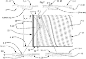
- a prior art sealing 1 of a joint between an inner tube connecting element 2 and at least one outer ventilation duct 3 or 4 is shown.
- the prior art sealing 1 is fastened at an end of the inner tube element 2 working as a duct connector being partially and with a close fit inserted into the end of at least one outer ventilation duct 3 and/or 4.
- This prior art sealing 1 is also shown in two side views in Fig. 7 , i.e. in one view at the topmost left corner in Fig. 7 and in one view at the topmost right corner in Fig. 7 .
- the sealing arrangement 10 shown in Figs. 4 to 26 according to the invention is adapted for air-tight or air-proof seal of joints between an inner tube connector 20 corresponding to the prior art connector 2 above and at least one outer ventilation duct 3 or 4, but may be used for interconnecting two outer ventilation ducts 3 and 4 and subsequently two joints, one joint at each end of the inner tube connector 20.
- the sealing arrangement 10 shown in Figs. 4 to 26 according to the invention is also adapted for air-tight or air-proof seal of joints between at least one ventilation duct fitting 5 and at least one outer ventilation duct 3, 4.
- Each ventilation duct fitting 5 see Figs.
- 4 to 7 may be a cap end, a lid, a damper, a diffuser, a measuring unit, a valve, a valve socket, a reducer, a saddle, a bend, a tee or the like used for plugging up an end of a ventilation duct 3, 4; interconnecting two outer ventilation ducts 3 and 4 extending in different directions; reducing sound in ventilation ducts; achieving air-tight seal between duct and a diffuser, a measuring unit, and between a valve and its valve socket or any other fitting.
- the invention and its application will be explained with reference to the inner tube connector 20 but the same principles of interconnecting each ventilation duct 3, 4 with any other and any number or combination of the above fittings 5 may be applied.
- This sealing arrangement 10 is also shown in two side views in Fig. 7 , i.e. in one view at the bottommost right corner in Fig. 7 and in one view at the bottommost left corner in Fig. 7 .
- the inner tube connector 20 is shown with one free end, i.e. an end connected to a ventilation duct 4 shown with dash dotted lines, to the left exposing the sealing arrangement 10 at that end, and with one end to the right connected with a slid-on ventilation duct 3 having the sealing 10 shown with grey lines as the sealing arrangement 10 is covered by this duct 3.
- the inventive sealing arrangement 10 shown in Figs. 4 to 18 is specifically designed for easy installment and secure and efficient air-tight sealing of joints at ventilation ducts, in particular helically wound lock seam ventilation ducts of sheet metal with a larger tube diameter and having at least one reinforcement bead 31, 41 extending helically along the length of the ventilation ducts forming a channel at area X in Fig 7 that is efficiently sealed off by the inventive sealing arrangement 10.
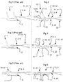
- FIGs. 8 and 11 to 16 there is shown an upper right view in smaller scale of a version of the sealing 10 being an inverted version of the left larger view if the sealing 10 has an L-shaped cross-section with only one protruding leg 12C.
- the upper right views in Figs. 8 and 11 to 16 may be the right-hand member or leg of a sealing 10 having an U-shaped cross-section with two protruding legs 12A and 12B or 12C and 12D of which the larger view corresponds to the left-hand leg 12A or 12C of the U with the base 11, 11A-B interconnecting these two legs of the U.
- a sealing 10 having for example an E-shaped cross-section with three protruding legs 12C and 12D and 12E of which the larger view corresponds to the leftmost leg 12C of the E with the base 11A-B interconnecting the three legs of the E similar to Fig. 11 .
- the reinforcement bead 31, 41 has the function of a support structure for stiffening ventilation ducts 3, 4 with larger diameters as these larger tubes would otherwise be too limpy/flabby/sloppy due to the fact that their tube thickness is small or thin in relation to their tube diameter.
- This thickness and diameter relationship would without the reinforcement bead 31, 41 make the whole duct "snake-like" by acting as a limpy elongated object, in principle similar to a limpy "sausage", when handled, used and suspended in a ventilation system and the duct would also run the risk of being undesirably deformed and/or bent during use negatively affecting the air-tightness of duct joints after assembly.
- the sealing arrangement 10 between the inner tube element 20 and each outer ventilation duct 3 or 4 extends continuously around the external circumference of each end 22 or 23 of the inner tube element 20.
- the inner tube element 20 comprises a first end 22 shown to the right in Fig 7 .
- This first end 22 at the right hand of Fig 7 is covered at least partly by the outer ventilation duct 3 being slid over it.
- the inner tube element comprises a second end 23 to the left in Fig 7 .
- This second inner tube element end 23 is exposed to the left in Fig 7 but may of course also be covered by another outer ventilation duct 4 being slid over it similar to the first end 22 forming a second joint.
- An end cap 5 only has one end 22, while for example a damper 5 has two ends 22 and 23.
- Each outer ventilation duct 3, 4 is a circular tube with at least one reinforcement bead 31, 41.
- the sealing arrangement 10 comprises at least one protrusion 12, 12A-E. Each protrusion extends from the sealing arrangement for sealing against the inner circumference of at least one outer ventilation duct 3, 4.
- the sealing protrusion comprises at least one outer portion 13, 13A-J. Each outer portion comprises at least one free end 14.
- Each outer sealing portion 13, 13A-E is adapted to physically and continuously contact the inner circumference of each outer ventilation duct 3, 4. This is achieved by continuously contacting an inner helically extending circumference provided by the at least one reinforcement bead 31, 41 at the joint between the first end 22 of the inner tube element 20 and the first outer ventilation duct 3.
- Each reinforcement bead 31, 41 extends helically along each outer ventilation duct 3 and/or 4 and forms a helically varying circumference and diameter of each outer ventilation duct 3 or 4.
- the sealing arrangement 10 achieves a continuous air-tight seal effect of each joint between the fitting 5 and the inner tube element 20 and the helically varying diameter of each outer duct 3 and/or 4.
- the sealing arrangement 10 achieves the continuous air-tight seal along the inside of the reinforcement bead when interconnected by means of the outer portion and free end 13, 13A-J, 14 of each sealing protrusion 12, 12A-E.
- the sealing arrangement 10 is pliable by means of each outer portion 13, 13A-J and free end 14 achieving the continuous air-tight seal by being in constant physical contact and intimately following the helically varying diameter of each outer ventilation duct 3 or 4 along the inside of the reinforcement bead at each duct joint in an air-tight conformable way, i.e. without leaving any open air channel X (see Fig 7 ) between the contacting areas of each outer sealing portion 13, 13A-J and free end 14 and the inner surface of the ventilation duct 3 and/or 4 including the inner surface of the larger duct diameter of each reinforcement bead 31 and/or 41.
- Each joint is an annular gap between a circular cylindrical outer surface of the fitting 5 and the inner tube connector 20 and the circular cylindrical inner surface of an outer ventilation duct 3 or 4 as any joint between such interconnected parts inevitably has tolerances making it difficult to have an air-proof joint without any additional type of sealing, as a sealing ring 10.
- the invention also relates to a method comprising the steps of extruding a continuous elongated body for forming the sealing arrangement 10 as a strand, bending a length of the sealing strand 10 into a circular annular shape, bringing the ends of the strand length together, and interconnecting the ends forming a sealing ring 10 having a U-shaped cross-section with a base or web 11, 11A-B interconnecting the protruding legs 12, 12A-E with free ends 14 of the U-shape.
- each protrusion 12, 12A-E extends into at least one free part, member or projection13, 13A-J with at least one free end 14 that may be straight but at least deviates partly from the plane of each protrusion.
- Protrusion 12, 12A-E may comprise at least one outer portion 13, 13A-J at its end deviating from the shape or protruding direction of the protrusion 12, 12A-E.
- Each free end 14 may have a shape with an outermost part or edge arranged at a distance SL from the protrusion 12, 12A-E in the lateral direction of the sealing arrangement 10.
- the free end 14 may extend freely in a direction and with a distance SL deviating at least partly from the extension plane of protrusion 12, 12A-E.
- the end 14 may extend freely in a direction substantially perpendicular or close to perpendicular to the extension plane of protrusion 12, 12A-E.
- the end 14 may extend freely a distance SL as measured from protrusion 12, 12A-E being at least equally long as the inner depth or inner height IBH of the reinforcement bead 31, 41 (see bottom most left view in Fig 7 ).
- the free end portion 13, 13A-J may also form the end of protrusion 12, 12A-E itself.
- the distance SL is measured along a plane or direction being substantially or close to substantially in parallel or in parallel with the plane of the base 11, 11A, 11B, i.e. distance SL is measured in the lateral direction of protrusion 12, 12A-E.
- Distance SL may also be equal to the length LB below.
- the size of the inner depth or inner height (IBH) of the reinforcement bead 31, 41 shown in the bottom most left view in Fig 7 depends on the thickness of the material that the ventilation ducts 3 and 4 are made of, e.g. 1.25 mm thick metal, and the diameter of the associated ventilation ducts 3 and 4.
- the size of each outer portion 13, 13A-J and its free end 14 is adapted to the IBH of the reinforcement bead 31, 41, the diameter of the fitting 5 and the inner connector 20, the diameter of the ventilation duct 3 and/or 4 and of course the tolerances of the annular gap between these parts, for achieving a secure air-tight seal between these associated parts.
- the outer ventilation duct 3, 4 is axially slidable onto an end 22 of the inner tube connector 20 and the fitting 5, whereby the sealing 10 is adapted to be located in and attached/fastened to the outer circumference of the inner tube connector 20 and fitting 5.
- the sealing 10 may be attached to a circumferential groove 21 in the inner tube connector 20 and fitting 5.
- the fastening of the sealing 10 is done prior to the sliding-on of each outer ventilation duct 3 or 4.
- the fastening of the sealing 10 may be realized by making the sealing an integrated part of the connector 20 and fitting 5.
- the outer ventilation duct 3, 4 could be equipped with the groove 21 instead of the inner tube connector 20 and fitting 5.
- the sealing 10 comprises a first sealing portion, i.e.
- the base 11, 11A-B which is adapted to abut, i.e. bottom with its underside against the outer circumference of the fitting 5 and the connector 20 or the bottom of the groove 21 formed in one of the ducts, e.g. the duct connector 20.
- the protrusions 12, 12A-E form a second sealing portion in the sealing 10 extending into a third primary sealing portion, i.e. the free sealing ends being either formed by the outer portions 13, 13A-J themselves or of the outmost free ends 14 or formed by a combination of these parts.
- the free ends 14 may be the bent-out or bent-in portions 13, 13A-J.
- the protrusions 12, 12A-E and free ends 14 and outer portions 13, 13A-J are adapted to commonly seal by physical, constant, and continuous contact with/against the inner circumference of the other pipe, i.e. the outer ventilation duct 3, 4, during and after assembly/interconnection enabling an air-tight joint.
- Each protrusion 12, 12A-E extends from the sealing base 11, 11A-B for sealing against the inner circumference of each outer ventilation duct 3, 4 in a radial plane P (see Fig 7 ) substantially perpendicular or perpendicular to the longitudinal direction of the ventilation duct before assembly of the ducts.
- outer portions 13, 13A-J and/or their free ends 14 may be deflected by being curved, folded, bended and/or joggled from or towards each other as shown in Figs. 4 to 26 .
- These outer portions 13A, 13B, 13C, 13D, 13E, 13F and their free ends 14 may be shaped as folded, inclined, bent-out or bent-in portions arranged at at least one protrusion or each protrusion 12, 12A-E (see Figs. 4 to 7 , 8 , 11 , 12 , and 19 to 22 ).
- the outer portions 13G, 13H and/or their free ends 14 may be shaped as shown in Figs. 13 to 14 and 23 to 24 with a hollow or solid round shaped cross-section similar to a circular bead and/or bulge arranged at the end of the substantially straight, straight or somewhat angled protrusions 12, 12A-E or the bead and/or bulge may form the free ends 14 arranged at the end of the outer portion 13G, 13H.
- These exemplifying shapes may have an outer radii R (solid and hollow ones) and inner radii r (only the hollow shapes) that are relatively large or small forming points, lines or areas of contact surfaces that achieve a more distinct and secure contact with the outer ventilation duct 3, 4 and its reinforcement bead 31, 41 creating an improved sealing when pressed against the outer ducts.
- These outer portions 13g, 13H may also be oriented to face in the same direction as in Figs. 23 and 24 or face towards different directions or extend in opposite directions inwards or outwards of the sealing 10 as in Figs. 13 and 14 , similar to the bent-in or bent-out versions in Figs. 19 to 21 .
- the outer portions 13, 13A-J and/or their free ends 14 may be shaped as shown in Figs. 15 to 16 and 25 to 26 with a hollow or solid polygonal shaped cross-section similar to a quadratic or rectangular or triangular bead and/or bulge arranged at the end of the substantially straight, straight, or somewhat angled protrusions 12, 12A-E or the bead and/or bulge may form the free ends 14 themselves arranged at the end of the outer portion 131, 13J.
- These exemplifying shapes may have relatively sharp corners forming points 14 that achieve a more distinct and secure contact with the outer ventilation duct 3, 4 and its reinforcement bead 31, 41 creating an improved sealing.
- outer portions 131 and 13J may also be oriented to face in the same direction as in Figs. 23 and 24 or face towards or from each other in different directions, i.e. extend in opposite directions inwards or outwards of the sealing 10 as in Figs. 13 and 14 , similar to the bent-in or bent-out versions in Figs. 19 to 21 and Figs 25 and 26 .
- the continuous air-tight contact is achieved by the protrusion 12, 12A-E and its free portions and ends 13, 13A-J, 14 being pliable and able to flex.
- This flexibility is required due to the fact that the reinforcement bead 31, 41 forms the helically extending hollow channel X passing past and beyond the width of the sealing 10 at the joint, which channel X is sealed air-tight by the inventive sealing 10 as shown in Fig 6 compared to the prior art sealing of Fig 3 .
- This is done by each outer portion 13, 13A-J being in constant physical contact and intimately following, by flexing, the helically varying diameter of each one outer ventilation duct at the bead 31, 41.
- each deflected, inclined, folded portion, rounded, polygonal and/or bent-out or bent-in portion 13, 13A-J and their free ends 14 is adapted to physically and continuously contact the inner circumference of each outer ventilation duct 3, 4 by flexing and/or bending, i.e. by being pliable enabling each in singular or in a combination of a number of these parts 13, 13A-J, 14, at least two or more than two, to intimately and in constant sealing contact follow the inner circumference of each outer ventilation duct and each reinforcement bead.
- This inventive sealing effect is also enhanced in that the outer portions 13, 13A-J and their free ends 14 are pressed against the inner circumference of the outer duct 3, 4 and deformed, i.e. shape-changed in an adaptable and ductile way during connection and after connection of the coupled ventilation parts 3, 4, 5, 20.
- the sealing 10 could use a combination of differently shaped outer portions 13, 13A-J and free ends 14, e.g. at least one bent-in or bent-out portion 13, 13A, 13B, 13C (from Figs. 8 , 11 and 19 to 21 ) and at least one straight portion 13D or at least two straight portions 13D and 13E (from Fig. 11 ).
- Another combination could be at least one folded portion 13F (from Figs. 12 and 22 ) and at least one straight portion 13D or at least two straight portions 13D and 13E (from Fig 11 ).
- Yet another combination could be at least one folded portion 13F (from Figs.
- a further combination could be at least one bent-in or bent-out portion 13, 13A, 13B, 13C (from Figs. 8 , 11 and 19 to 21 ) and at least one rounded portion 13G or 13H or at least two rounded portions 13G and 13H (from Figs. 13 to 14 and 23 to 24 ).
- Each of the above combinations could be complemented with at least one hollow or solid polygonal shaped cross-section 131 and/or 13J (from Figs.
- each of the above combinations could be combined singularly or in pairs or in any other number of combinations, e.g. combinations of one or more bent portions 13A-D and/or one or more rounded portions 13G-H and/or one or more polygonal portions 13I-J and/or one or more inclined portions 13F are possible besides the shown ones.
- the sealing 10 is foldable by being bent downwards towards the fitting 5 and inner tube connector 20 when each outer ventilation duct 3, 4 is slid onto it as shown in Figs. 4 to 7 .
- the sealing 10, i.e. its protrusions 12, 12A-E and free ends 14 at the outer portions 13, 13A-J may be folded, e.g. at least 30° or closer to 45° or about 60° to 90°, preferably 80° to 90°.
- the protrusions 12, 12A-E with their ends 14 may be folded between one position in which the protrusions extend in a substantially perpendicular direction or radially in relation to the longitudinal direction of the fitting 5 and connector 20 and another position in which the protrusions extend in a direction being angled in relation to the longitudinal direction of the fitting 5 or connector 20 or substantially in parallel with the longitudinal direction of the duct.
- the folding or bending of the sealing protrusions 12, 12A-E occurs of course to the left if a first ventilation duct 3 is slid onto the fitting 5 and connector 20 from the right as shown in Figs. 4 to 7 and occurs of course to the right if a second ventilation duct 4 is slid onto the fitting 5 and connector 20 from the left (not shown).
- the sealing ring 10 may be made of at least one elastic/ductile material, e.g. a polymer, an EPDM or Nitrile rubber or the like, with a cross-section shape similar to an U in Figs 4 to 10 and 19 to 26, and a L or F or E in Figs. 11 to 18 when viewed from the end, i.e. when viewed in a direction along or in parallel with the length of the not yet circularly formed strip or strand or when viewed in a direction perpendicular to the length of the ventilation ducts 3, 4.
- the protrusions 12, 12A-E form the legs of the U, the L, the F, and the E.
- Each protrusion 12, 12A-E extends in a plane, which plane may have a normal vector substantially parallel or angled in relation to the longitudinal direction of the ducts 3, 4 when the sealing is fastened on the fitting 5 and connector 20.
- the protruding legs 12, 12A-E may extend in a substantially radial direction in relation to the longitudinal direction of the ducts or in a direction not being substantially perpendicular to the lengthwise direction of the duct 3, 4, but somewhat angled/inclined in relation therewith (see angle ⁇ in Figs 11 to 18 being perpendicular or substantially perpendicular to the plane of the sealing web 11, 11A-B or angled between 10° to 89° from the sealing web plane 11, 11A, 11B or angled between about 10° to 90° or more as measured from the longitudinal direction of the ducts 3, 4, the fitting 5 and the connector 20.
- the sealing 10 comprises contact surfaces formed by at least parts of but also the whole of the protrusions 12, 12A-E and the outer portions 13, 13A-J and their free ends 14 of which at least one part of one of these contact surfaces slides in constant physical contact without interruption against the inner surfaces and contours of the ventilation ducts 3 and 4 and their reinforcement beads 31, 41 and/or any other protrusion/outer portion when the ducts are connected by sliding onto and over and past each sealing 10.
- This constant contact is achieved at each end of the inner tube connecting element 20.
- this uninterrupted physical contact between at least one part of the sealing 10 and the inner surface of the ventilation ducts 3 and 4 including their reinforcement beads 31 and 41 effects the efficient and secure sealing effect of each duct joint according to the invention.
- each outer portion 13, 13A-J with its free ends 14 reaches further out due to its shape and length, whereby there is a guaranteed and secure constant/continuous contact between the sealing 10 and the inner surfaces of the ventilation ducts 3, 4 including their reinforcement beads 31, 41.
- This improved ability of reaching out and getting into and upholding sealing contact with the inner surfaces of the ventilation ducts 3, 4 including their reinforcement beads 31, 41 is guaranteed by the deflection of outer portions 13, 13A-J and number of protrusions and outer portions, e.g. one protrusion with one outer portions seals efficiently, but a protrusion with two outer portions seals more efficiently.
- outer portions 13, 13A-J all have a shape and size and thickness that form points, lines or areas of contact surfaces that achieve an adaptable and a more distinct and secure contact with the outer ventilation duct 3, 4 and its reinforcement bead 31, 41 creating an improved sealing when pressed against the inside of the outer ducts.
- This sealing effect is also improved by applying more than one protrusion which in turn may have more than one outer portion of which each outer portion may have more than one free end as the double folding gets tighter and each protrusion, outer portion and free end cooperates with the other associated sealing parts further enhancing the sealing and increasing the sealing area and sealing parts/surfaces.
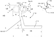
- Each outer portion 13, 13A-J of the sealing 10 extends a distance HS from the outer circumference of the fitting 5, 20 and deviate at least partly the distance SL from the extension plane of the protrusions 12, 12A-E.
- Each outer portion 13, 13A-J of the sealing 10 may be bent in a curve being a portion of a semicircle or substantially a whole circle or a full circle with a radius R that may be adapted for different dimensions of ducts 3, 4 and reinforcement beads 31, 41.
- Fig 8 shows outer portions 13A and 13B being bent-out from each other and the sealing 10.
- Fig 11 shows outer portions 13A and 13C on protrusion 12C, one portion 13A shown in dashed lines bent-out to the left from another portion 13C being bent-in to the right and towards the sealing 10.
- Protrusions 12D-E and outer portions 13D-E are shown straight and in dashed lines as other possible shapes and types of sealing 10.
- Distance HS is large enough for one protrusion to be bent into sealing contact with any other protrusion if more than one protrusion is used.
- Each protrusion 12, 12A-E may have a varying thickness T, t such that the protrusions are pliable, e.g. by being bendable in a sufficiently flexible way.
- This varying thickness achieves a controllable and diameter compensating and faulty correcting function enhancing the sealing effect as at least parts of but also the whole of the protrusions 13, 13A-J and their ends 14 may form contact surfaces of which at least one part of one of these contact surfaces efficiently and securely slides in constant physical contact without interruption against the inner surfaces and contours of the ventilation ducts 3 and 4 and their reinforcement beads 31, 41 when the ducts are connected by sliding onto and over and past each sealing 10 at each end 22, 23 of the inner tube connecting element 20.
- the sealing 10 shown in Figs. 11 to 26 comprises the left protrusion 12C and the outer portion 13A or 13C while the other protrusions 12D and 12E are extending in a substantially straight direction, even though the rightmost protrusion 12D as an example has an inclined surface facing inwards of the sealing towards the other two protrusions.
- the rightmost protrusion 12D may extend with an angle ⁇ not being 90°.
- Each protrusion 12C, 12D and 12E comprises free ends 13C, 13D, 13E, 14.
- Each protrusion 12C, 12D and 12E may form legs of the L-, F- or E-shaped cross-section.
- Protrusion 12C may extend in a direction not being aligned or in parallel with each of the other protrusions 12D, 12E by extending in an angle ⁇ larger or less than 90o from the longitudinal direction of the ducts 3, 4 and the base 11, 11A, 11B of the sealing 10. At least one or all of the protrusions 12, 12A-E may extend with an angle ⁇ being 90o or deviating from 90o. Leftmost protrusion 12C may extend with an angle ⁇ being about 90°or extend in parallel with the other protrusions 12d and 12E. If the sealing 10 comprises three protrusions 12C, 12D, and 12E as in Fig.
- the base 11 of the sealing 10 is made up of one/first web length 11A between the left outmost protrusion 12C and the middle protrusion 12E and another/second web length 11B to the right between the right outmost protrusion 12D and the middle protrusion 12E.
- the sealing 10 comprising protrusions 12, 12A-E with outer portions 13, 13A-J and free ends 14 may have each end 14 similar to a lip over which each ventilation duct 3, 4 is slid with a close fit so that each lip is pressed and bent into sealing contact with the outer duct 3, 4 and the inner tube connector 20.
- the sealing 10 may have only one lip 14 if only one protrusion is present.
- Each free end 14 may be split into two lips as shown in Fig 21 , similar to a snake's tongue. This shape gives an even better sealing effect as at least two free ends 14 on one protrusion 12, 12A-E with at least one outer portion 13, 13A-D cooperate and contact the outer ducts with a larger surface.
- each protrusion having at least one outer portion 13, 13A-D for improving the sealing effect further by means of a further increased contact surface.
- the sealing 10 may have each lip 14 pressed and bent into sealing contact with the outer duct 3, 4 and the fitting 5 and/or the inner tube connector 20 and into sealing contact with another lip if more than two lips 14 are used or the outer duct 3, 4 and its beads 31, 41 are pressed into contact with more than one lip if at least two protrusions are used of which each protrusion may have at least one lip 14.
- the outer duct 3, 4 and its beads 31, 41 may be pressed into contact with at least one lip (or two lips if more than two protrusions are used) as not all protrusions but one must be sufficiently long to achieve the sealing effect, it suffices that only one protrusion has a deflection, bent-out or bent-in portion or rounded or polygonal shape or sufficient large size or is long enough for achieving the inventive sealing effect between the fitting 5, 20 and the inside of the ventilation ducts 3, 4 and their reinforcement beads 31, 41 by being able to maintain sealing contact against the outer ventilation parts 3, 4, 5, 20.
- Each protrusion 12, 12A-E having at least one outer portion 13, 13A-D may maintain sealing contact against any other protrusion 12, 12A-E and/or any other outer portion 13, 13A-D and each ventilation part 3, 4, 5, 20 if more than one protrusion/outer portion is used (see Figs 4 to 6 ).
- Each protrusion 12,12A-E is folded double, at least along a part of its free length, e.g. at least along the outer portion 13, 13A-J and/or at least along the free end 14 by being bent downwards ( Figs. 6 and 7 ) achieving the above explained sealing contact, such that the double fold shape gives an air-tight sealing effect when the ventilation ducts 3, 4 have been introduced sufficiently far over each end 22 of the fitting 5/inner tube connecting element 20.
- the middle protrusion 12E has a middle free end 13E, 14 that may be bent (not shown) in the similar way as the other portions and free ends 13A-D, 14 or be straight as shown in Fig. 11 .
- the middle protrusion 12E may be bent (not shown) in the similar way as the other protrusions 12A-D when the ventilation ducts 3, 4 are slid-on the connector 20 or be kept straight if the protruding length is shorter than the other protrusions such that the ventilation duct 3, 4 is not able to contact and thereby not able to press the middle protrusion 12E downwards by bending it towards the connector 20 as shown in Fig. 11 .
- the preferred thickness T, t of the sealing 10 and its protrusions 12A-E and outer portions 13, 13A-J, 14 also optimizes the flexibility and rigidity of the parts of the sealing 10 that carry the air-proof seal into effect without making the sealing 10 and its associated parts too "limpy".
- the free end 14 may have another thickness, preferably smaller, than the remaining outer portion 13, 13A-J and/or the protrusion 12, 12A-E.
- Legs 12A and 12C are shown as the left ones in the Figs. 8 , 11 and 21 to 26 and the legs 12B and 12D are shown as the right ones in the same Figs, but this order depends on from which direction the sealing 10 is viewed.
- these legs 12A-E, e.g. 12A, 12B, 12C and 12D may be angled with angle ⁇ to the left or to the right in these figures depending on the application of the sealing 10.
- the outer portions 13, 13A-J, 14 may be bent to the left in Figs. 8 to 20 or to the right in these figures depending on from which direction each ventilation duct 3 or 4 is introduced onto and slid over the sealing 10.
- Fig. 11 shows the leg or lip 12C with outer portions 13A and 13C, shown in continuous and dotted lines, deflected or bent to the left or the right depending on if the sealing 10 has the right short leg 12D closest to an end 22, 23 of the connector 20 or if the longer left leg 12C is placed closest to an connector end when attached to the connector. If the short leg 12D is closest to a connector end, the outer portion 13C, 14 of the longer leg 12C is deflected or bent to the right, i.e. the bent portion 13C of the long leg 12C is deflected or bent towards the short leg 12D.
- the outer portion 13A, 14 of the longer leg 12C is deflected or bent to the left of Fig. 11 , i.e. the outer portion 13A of the longer leg 12C is deflected or bent away from the short leg 12D.
- a width WB of the base 11, 11A, 11B of the sealing 10 as measured in the plane of the underside/bottom of the sealing base is about 10-50% less than the width WE of the sealing 10 as measured at the level of the outer portion 13, 13A-J, 14 above the base but measured in a plane in parallel with the sealing base.
- the height HS of the sealing 10 as measured vertically from the underside/bottom of the sealing base 11, 11A, 11B or radially from the ducts 3, 4 to the upper end of the free ends 13, 13A-J, 14 is about 10-40% larger than the width WB of the sealing as measured in and from the plane of the underside/bottom of the sealing base 11, 11A, 11B to the outmost corners/edges 14 of the sealing laterally, i.e. a longitudinal direction of the ducts 3, 4.
- a height h of each protrusion 12, 12A-E is measured in the same way as HS and h is adapted to the application of each sealing 10.
- each outer portion 13, 13A-J amounts to at least 30 to 60% of the height HS.
- the length or height LB may be equal to the height of a symmetrically shaped outer portion 13, 13A-J or the radius R or r or the diameter if the shape of the outer portion 13, 13A-J is rounded or circular.
- the sealing 10 may have the thickness T, t of each protrusion 12, 12A-E decreasing from the base 11, 11A, 11B towards the end 14 of each outer portion 13, 13A-J for better flexibility and adaptability to the varying diameters of the duct 3, 4 and the beads 31, 41 (see Figs. 8 to 13 ).
- One example of the thickness of each protrusion 12, 12A-E decreases from T being between 1 and 5 mm at the base 11, 11A, 11B to t being between 0.5 and 3 mm at the end 14.
- the thickness T, t may be equally large along the whole protrusions 12, 12A-E.
- the height h may be equal to thickness T, t in the sealing 10.
- no numerals T, t are shown but thicknesses are of course present in these sealing arrangements 10 and may be varied in the same way as the thicknesses in the sealing arrangements of Figs 4 to 13 .
- the sealing 10 may also be made of two different elastic materials to achieve the same function, depending on application, e.g. its outer portions and/or free ends 13, 13A-J, 14 may be made of one elastic material and the protrusions 12, 12A-E may be made of another elastic material, the same goes for the sealing base 11, 11A-B.
- each end 14 and/or outer portion 13, 13A-J may have radius R, r of curvature of between approximately 5 mm to approximately 20 mm depending on the size of the ventilation ducts 3, 4 and the fitting 5 and inner tube element 20.
- a first aspect of the invention concerns a sealing arrangement 10 for a joint between at least one ventilation duct fitting 5, 20 and at least one outer ventilation duct 3, 4, each outer ventilation duct comprising at least one helically extending reinforcement bead 31, 41, wherein the sealing arrangement extends continuously around the external circumference of at least one end 22, 23 of the ventilation duct fitting and comprises at least one protrusion 12, 12A-E extending outwards from the external circumference of the ventilation duct fitting for sealing against the inner circumference of the outer ventilation duct, the sealing arrangement further comprising at least one outer portion 13, 13A-J, 14 at the protrusion, wherein the outer portion is adapted to physically and continuously contact the inner circumference of the ventilation duct and an inner circumference of the reinforcement bead at the joint, which reinforcement bead forms a helically varying diameter of the outer ventilation duct, whereby the sealing arrangement 10 achieves an air-tight seal of the joint between the ventilation duct fitting, the inner circumference of the outer ventilation duct and the helically varying inner
- each protrusion 12, 12A-E and its outer portion 13, 13A-J, 14 may be smooth by being smoothly bent as shown in Figs 4 to 6 , 8 , 11 , 13 , 14 , 19 to 21 , 23, and 24 .
- the transition between each protrusion 12, 12A-E and its outer portion 13, 13A-J, 14 may be more distinct by being angled and/or more sharply and/or distinctly curved as shown by Figs 12 , 15 , 16 , 22 , 25, and 26 .
- each protrusion 12, 12A-E and its outer portion 13, 13A-J, 14 may be more pointy with at least one corner area and/or be more or less sharp or curved as shown by Figs 12 , 15 , 16 , 22 , 25, and 26 .
- Each outer portion 13, 13A-J, 14 may comprise at least one tip or point and/or sharp corner area as shown by Figs 12 , 15 , 16 , 22 , 25, and 26 .
- the protrusion and its outer portion of the sealing 10 is adapted and shaped such that they extend and/or face in different planes and/or directions to reach and be in constant physical contact and intimately following the inner circumference of the ventilation duct including its helically varying inner circumference on the inside of the reinforcement bead when the ventilation duct fitting and the outer ventilation duct are interconnected.
- this enables for the protrusion 12, 12A-E and its outer portion 13, 13A-J, 14 to complement each other when pressed down by the outer ventilation duct at interconnection by being able to reach more far away areas and surfaces and also to be able to seal against larger inner surfaces of the duct 3, 4 and the spirally wound reinforcement bead 31, 41 and larger outer surfaces of the inner tube element 2 and/or the ventilation fitting 5 compared to prior art sealings.
- a second aspect of the invention concerns a sealing arrangement 10 according to the first aspect, wherein each outer portion 13, 13A-J has at least one free end 14 arranged at a distance SL from the protrusion 12, 12A-E, which distance SL, measured along a plane being substantially in parallel with the longitudinal direction of the ventilation duct fitting 5, 20, is at least equal to an inner height IBH of the helically varying reinforcement bead 31, 41.
- a third aspect of the invention concerns a sealing arrangement 10 according to the second aspect, wherein the distance SL from the at least one protrusion 12, 12A-E is larger than the inner height IBH of the helical reinforcement bead 31, 41.
- a fourth aspect of the invention concerns a sealing arrangement 10 according to any preceding aspect, wherein the sealing arrangement comprises at least two protrusions 12, 12A-E.
- a fifth aspect of the invention concerns a sealing arrangement 10 according to any preceding aspect, wherein the sealing arrangement comprises at least two outer portions 13, 13A-J, 14.
- a sixth aspect of the invention concerns a sealing arrangement 10 according to the fifth aspect, wherein the sealing arrangement 10 comprises at least two free ends 14.
- a seventh aspect of the invention concerns a sealing arrangement 10 according to any preceding aspect, wherein the outer portion 13, 13A-J extends in a direction deviating from the extension plane of the associated protrusion 12, 12A-E.
- An eighth aspect of the invention concerns a sealing arrangement 10 according to any preceding aspect, wherein at least one outer portion 13, 13A-J, 14 is arranged at each end of each protrusion 12, 12A-E.
- a ninth aspect of the invention concerns a sealing arrangement 10 according to any of the fifth to eighth aspects when the seventh and the eighth aspects are dependent on the fourth aspect, wherein a first outer portion 13, 13A-J at the end of a first protrusion 12A, 12C extends in another direction in relation to a second outer portion 13B-J, 14 arranged at the end of a second protrusion 12B, 12D.
- a tenth aspect of the invention concerns a sealing arrangement 10 according to any of the fourth to ninth aspects, wherein the outer portions 13, 13A-J, 14 at the ends of the protrusions 12, 12A-E extend in opposite directions in relation to each other.
- An eleventh aspect of the invention concerns a sealing arrangement 10 according to any of the fourth to tenth aspects, wherein the outer portions 13, 13A-J, 14 at the ends of the protrusions 12A-E have inverted shapes in relation to each other.
Landscapes
- Engineering & Computer Science (AREA)
- General Engineering & Computer Science (AREA)
- Mechanical Engineering (AREA)
- Physics & Mathematics (AREA)
- Fluid Mechanics (AREA)
- Chemical & Material Sciences (AREA)
- Combustion & Propulsion (AREA)
- Duct Arrangements (AREA)
- Gasket Seals (AREA)
- Joints Allowing Movement (AREA)
Priority Applications (2)
| Application Number | Priority Date | Filing Date | Title |
|---|---|---|---|
| PL13791790T PL2923156T3 (pl) | 2012-11-13 | 2013-11-12 | Uszczelnienie połączeń między przewodami wentylacyjnymi a łącznikami |
| RS20201306A RS61042B1 (sr) | 2012-11-13 | 2013-11-12 | Zaptivanje spojeva između ventilacionih kanala i priključaka |
Applications Claiming Priority (2)
| Application Number | Priority Date | Filing Date | Title |
|---|---|---|---|
| SE1251289A SE537430C2 (sv) | 2012-11-13 | 2012-11-13 | Tätning av fogar mellan ventilationsrör och detaljer |
| PCT/EP2013/073591 WO2014076065A1 (en) | 2012-11-13 | 2013-11-12 | Sealing of joints between ventilation ducts and fittings |
Publications (2)
| Publication Number | Publication Date |
|---|---|
| EP2923156A1 EP2923156A1 (en) | 2015-09-30 |
| EP2923156B1 true EP2923156B1 (en) | 2020-10-07 |
Family
ID=49584720
Family Applications (1)
| Application Number | Title | Priority Date | Filing Date |
|---|---|---|---|
| EP13791790.2A Active EP2923156B1 (en) | 2012-11-13 | 2013-11-12 | Sealing of joints between ventilation ducts and fittings |
Country Status (9)
| Country | Link |
|---|---|
| EP (1) | EP2923156B1 (sv) |
| DK (1) | DK2923156T3 (sv) |
| ES (1) | ES2838624T3 (sv) |
| HU (1) | HUE051991T2 (sv) |
| PL (1) | PL2923156T3 (sv) |
| RS (1) | RS61042B1 (sv) |
| RU (1) | RU2652956C2 (sv) |
| SE (1) | SE537430C2 (sv) |
| WO (1) | WO2014076065A1 (sv) |
Family Cites Families (5)
| Publication number | Priority date | Publication date | Assignee | Title |
|---|---|---|---|---|
| US4487421A (en) * | 1983-05-10 | 1984-12-11 | Hamilton Kent Manufacturing Company, Inc. | Pipe gasket with reinforcing means in its base self-energizing |
| ATE231596T1 (de) * | 1998-11-06 | 2003-02-15 | Lindab Ab | Rohrförmiges element mit abdichtvorrichtung und verfahren zur herstellung von rohrförmigen elementen |
| US6739632B1 (en) * | 2001-09-24 | 2004-05-25 | Hamlin Sheet Metal, Incorporated | Method and apparatus for coupling HVAC conduits |
| EP2059728A4 (en) | 2006-09-08 | 2011-01-26 | Lindab Ab | ARRANGEMENT FOR CONNECTING PIPE ELEMENTS IN A VENTILATION CHANNEL SYSTEM |
| RU2339882C1 (ru) * | 2007-03-12 | 2008-11-27 | Джинвунг Текнолоджи | Спиральный воздуховод |
-
2012
- 2012-11-13 SE SE1251289A patent/SE537430C2/sv unknown
-
2013
- 2013-11-12 RS RS20201306A patent/RS61042B1/sr unknown
- 2013-11-12 RU RU2015122730A patent/RU2652956C2/ru active
- 2013-11-12 ES ES13791790T patent/ES2838624T3/es active Active
- 2013-11-12 PL PL13791790T patent/PL2923156T3/pl unknown
- 2013-11-12 DK DK13791790.2T patent/DK2923156T3/da active
- 2013-11-12 EP EP13791790.2A patent/EP2923156B1/en active Active
- 2013-11-12 WO PCT/EP2013/073591 patent/WO2014076065A1/en active Application Filing
- 2013-11-12 HU HUE13791790A patent/HUE051991T2/hu unknown
Non-Patent Citations (1)
| Title |
|---|
| None * |
Also Published As
| Publication number | Publication date |
|---|---|
| WO2014076065A1 (en) | 2014-05-22 |
| DK2923156T3 (da) | 2020-10-19 |
| EP2923156A1 (en) | 2015-09-30 |
| SE1251289A1 (sv) | 2014-05-14 |
| PL2923156T3 (pl) | 2021-01-25 |
| RU2015122730A (ru) | 2017-01-10 |
| SE537430C2 (sv) | 2015-04-28 |
| RU2652956C2 (ru) | 2018-05-03 |
| RS61042B1 (sr) | 2020-12-31 |
| ES2838624T3 (es) | 2021-07-02 |
| HUE051991T2 (hu) | 2021-04-28 |
Similar Documents
| Publication | Publication Date | Title |
|---|---|---|
| RU2239118C2 (ru) | Трубчатый элемент со средствами герметизации и способ изготовления трубчатого элемента | |
| US7523964B2 (en) | Sealing gasket for ventilation duct system | |
| US20070246938A1 (en) | Press fitting arrangement with a pre-press leak indicator sealing ring | |
| CN101147022B (zh) | 用于管接头的固定件 | |
| US8505985B2 (en) | Coupling device | |
| US20130257045A1 (en) | Housing type pipe joint | |
| EP2759779B1 (en) | Ventilation duct coupling and method of manufacturing thereof | |
| CN103062539A (zh) | 带有密封件的异形夹 | |
| CN105637278A (zh) | 具有动态轴向约束系统的管道联接件 | |
| JP2007517738A (ja) | 流体投与装置 | |
| US20110132487A1 (en) | Tubular Component | |
| EP2923156B1 (en) | Sealing of joints between ventilation ducts and fittings | |
| EP1197686B1 (en) | Superelastic seal for liquid natural gas processing plants | |
| KR20190076232A (ko) | 배관용 조인트 | |
| US6378561B1 (en) | Self-sealing flexible metal hose | |
| EP2145136B1 (en) | Method for forming a seal between air ducts and/or terminal units thereof and an air duct | |
| KR101161717B1 (ko) | 배관용 조인트 | |
| JP3591693B2 (ja) | ピンチバルブ | |
| US20220373114A1 (en) | Pipe Connector And An Assembly Of A Pipe Connector With At Least Two Pipes | |
| JP5296653B2 (ja) | パッキン及びパッキンの装着方法 | |
| CN220566561U (zh) | 一种金属密封圈 | |
| JP7424722B2 (ja) | 配管の分岐構造 | |
| JP7269561B2 (ja) | 円筒管接続部のシール部材 | |
| EP1325257B1 (en) | Sealing ring | |
| EP3586053A1 (en) | Pipe seal, pipe assembly, and a method of forming a seal |
Legal Events
| Date | Code | Title | Description |
|---|---|---|---|
| PUAI | Public reference made under article 153(3) epc to a published international application that has entered the european phase |
Free format text: ORIGINAL CODE: 0009012 |
|
| 17P | Request for examination filed |
Effective date: 20150528 |
|
| AK | Designated contracting states |
Kind code of ref document: A1 Designated state(s): AL AT BE BG CH CY CZ DE DK EE ES FI FR GB GR HR HU IE IS IT LI LT LU LV MC MK MT NL NO PL PT RO RS SE SI SK SM TR |
|
| AX | Request for extension of the european patent |
Extension state: BA ME |
|
| DAX | Request for extension of the european patent (deleted) | ||
| REG | Reference to a national code |
Ref country code: DE Ref legal event code: R079 Ref document number: 602013073129 Country of ref document: DE Free format text: PREVIOUS MAIN CLASS: F24F0013020000 Ipc: F16L0025000000 |
|
| GRAP | Despatch of communication of intention to grant a patent |
Free format text: ORIGINAL CODE: EPIDOSNIGR1 |
|
| STAA | Information on the status of an ep patent application or granted ep patent |
Free format text: STATUS: GRANT OF PATENT IS INTENDED |
|
| RIC1 | Information provided on ipc code assigned before grant |
Ipc: F16L 21/035 20060101ALI20200512BHEP Ipc: F16L 25/00 20060101AFI20200512BHEP Ipc: F24F 13/02 20060101ALI20200512BHEP Ipc: F16L 17/025 20060101ALI20200512BHEP |
|
| INTG | Intention to grant announced |
Effective date: 20200604 |
|
| GRAS | Grant fee paid |
Free format text: ORIGINAL CODE: EPIDOSNIGR3 |
|
| GRAA | (expected) grant |
Free format text: ORIGINAL CODE: 0009210 |
|
| STAA | Information on the status of an ep patent application or granted ep patent |
Free format text: STATUS: THE PATENT HAS BEEN GRANTED |
|
| AK | Designated contracting states |
Kind code of ref document: B1 Designated state(s): AL AT BE BG CH CY CZ DE DK EE ES FI FR GB GR HR HU IE IS IT LI LT LU LV MC MK MT NL NO PL PT RO RS SE SI SK SM TR |
|
| REG | Reference to a national code |
Ref country code: GB Ref legal event code: FG4D |
|
| REG | Reference to a national code |
Ref country code: AT Ref legal event code: REF Ref document number: 1321494 Country of ref document: AT Kind code of ref document: T Effective date: 20201015 Ref country code: CH Ref legal event code: EP |
|
| REG | Reference to a national code |
Ref country code: DK Ref legal event code: T3 Effective date: 20201014 |
|
| REG | Reference to a national code |
Ref country code: DE Ref legal event code: R096 Ref document number: 602013073129 Country of ref document: DE |
|
| REG | Reference to a national code |
Ref country code: FI Ref legal event code: FGE |
|
| REG | Reference to a national code |
Ref country code: IE Ref legal event code: FG4D |
|
| REG | Reference to a national code |
Ref country code: CH Ref legal event code: NV Representative=s name: ISLER AND PEDRAZZINI AG, CH |
|
| REG | Reference to a national code |
Ref country code: RO Ref legal event code: EPE |
|
| REG | Reference to a national code |
Ref country code: SE Ref legal event code: TRGR |
|
| REG | Reference to a national code |
Ref country code: NL Ref legal event code: FP |
|
| PGFP | Annual fee paid to national office [announced via postgrant information from national office to epo] |
Ref country code: ES Payment date: 20201216 Year of fee payment: 8 |
|
| REG | Reference to a national code |
Ref country code: EE Ref legal event code: FG4A Ref document number: E020206 Country of ref document: EE Effective date: 20201221 |
|
| PGFP | Annual fee paid to national office [announced via postgrant information from national office to epo] |
Ref country code: RS Payment date: 20201029 Year of fee payment: 8 |
|
| REG | Reference to a national code |
Ref country code: NO Ref legal event code: T2 Effective date: 20201007 |
|
| REG | Reference to a national code |
Ref country code: HU Ref legal event code: AG4A Ref document number: E051991 Country of ref document: HU |
|
| PG25 | Lapsed in a contracting state [announced via postgrant information from national office to epo] |
Ref country code: GR Free format text: LAPSE BECAUSE OF FAILURE TO SUBMIT A TRANSLATION OF THE DESCRIPTION OR TO PAY THE FEE WITHIN THE PRESCRIBED TIME-LIMIT Effective date: 20210108 Ref country code: PT Free format text: LAPSE BECAUSE OF FAILURE TO SUBMIT A TRANSLATION OF THE DESCRIPTION OR TO PAY THE FEE WITHIN THE PRESCRIBED TIME-LIMIT Effective date: 20210208 |
|
| REG | Reference to a national code |
Ref country code: LT Ref legal event code: MG4D |
|
| PG25 | Lapsed in a contracting state [announced via postgrant information from national office to epo] |
Ref country code: IS Free format text: LAPSE BECAUSE OF FAILURE TO SUBMIT A TRANSLATION OF THE DESCRIPTION OR TO PAY THE FEE WITHIN THE PRESCRIBED TIME-LIMIT Effective date: 20210207 Ref country code: LV Free format text: LAPSE BECAUSE OF FAILURE TO SUBMIT A TRANSLATION OF THE DESCRIPTION OR TO PAY THE FEE WITHIN THE PRESCRIBED TIME-LIMIT Effective date: 20201007 Ref country code: BG Free format text: LAPSE BECAUSE OF FAILURE TO SUBMIT A TRANSLATION OF THE DESCRIPTION OR TO PAY THE FEE WITHIN THE PRESCRIBED TIME-LIMIT Effective date: 20210107 |
|
| PG25 | Lapsed in a contracting state [announced via postgrant information from national office to epo] |
Ref country code: HR Free format text: LAPSE BECAUSE OF FAILURE TO SUBMIT A TRANSLATION OF THE DESCRIPTION OR TO PAY THE FEE WITHIN THE PRESCRIBED TIME-LIMIT Effective date: 20201007 |
|
| REG | Reference to a national code |
Ref country code: ES Ref legal event code: FG2A Ref document number: 2838624 Country of ref document: ES Kind code of ref document: T3 Effective date: 20210702 |
|
| REG | Reference to a national code |
Ref country code: DE Ref legal event code: R097 Ref document number: 602013073129 Country of ref document: DE |
|
| PG25 | Lapsed in a contracting state [announced via postgrant information from national office to epo] |
Ref country code: SK Free format text: LAPSE BECAUSE OF FAILURE TO SUBMIT A TRANSLATION OF THE DESCRIPTION OR TO PAY THE FEE WITHIN THE PRESCRIBED TIME-LIMIT Effective date: 20201007 Ref country code: MC Free format text: LAPSE BECAUSE OF FAILURE TO SUBMIT A TRANSLATION OF THE DESCRIPTION OR TO PAY THE FEE WITHIN THE PRESCRIBED TIME-LIMIT Effective date: 20201007 Ref country code: LT Free format text: LAPSE BECAUSE OF FAILURE TO SUBMIT A TRANSLATION OF THE DESCRIPTION OR TO PAY THE FEE WITHIN THE PRESCRIBED TIME-LIMIT Effective date: 20201007 Ref country code: LU Free format text: LAPSE BECAUSE OF NON-PAYMENT OF DUE FEES Effective date: 20201112 Ref country code: SM Free format text: LAPSE BECAUSE OF FAILURE TO SUBMIT A TRANSLATION OF THE DESCRIPTION OR TO PAY THE FEE WITHIN THE PRESCRIBED TIME-LIMIT Effective date: 20201007 |
|
| PLBE | No opposition filed within time limit |
Free format text: ORIGINAL CODE: 0009261 |
|
| STAA | Information on the status of an ep patent application or granted ep patent |
Free format text: STATUS: NO OPPOSITION FILED WITHIN TIME LIMIT |
|
| 26N | No opposition filed |
Effective date: 20210708 |
|
| PG25 | Lapsed in a contracting state [announced via postgrant information from national office to epo] |
Ref country code: AL Free format text: LAPSE BECAUSE OF FAILURE TO SUBMIT A TRANSLATION OF THE DESCRIPTION OR TO PAY THE FEE WITHIN THE PRESCRIBED TIME-LIMIT Effective date: 20201007 |
|
| PG25 | Lapsed in a contracting state [announced via postgrant information from national office to epo] |
Ref country code: SI Free format text: LAPSE BECAUSE OF FAILURE TO SUBMIT A TRANSLATION OF THE DESCRIPTION OR TO PAY THE FEE WITHIN THE PRESCRIBED TIME-LIMIT Effective date: 20201007 |
|
| PG25 | Lapsed in a contracting state [announced via postgrant information from national office to epo] |
Ref country code: IS Free format text: LAPSE BECAUSE OF FAILURE TO SUBMIT A TRANSLATION OF THE DESCRIPTION OR TO PAY THE FEE WITHIN THE PRESCRIBED TIME-LIMIT Effective date: 20210207 Ref country code: TR Free format text: LAPSE BECAUSE OF FAILURE TO SUBMIT A TRANSLATION OF THE DESCRIPTION OR TO PAY THE FEE WITHIN THE PRESCRIBED TIME-LIMIT Effective date: 20201007 Ref country code: MT Free format text: LAPSE BECAUSE OF FAILURE TO SUBMIT A TRANSLATION OF THE DESCRIPTION OR TO PAY THE FEE WITHIN THE PRESCRIBED TIME-LIMIT Effective date: 20201007 Ref country code: CY Free format text: LAPSE BECAUSE OF FAILURE TO SUBMIT A TRANSLATION OF THE DESCRIPTION OR TO PAY THE FEE WITHIN THE PRESCRIBED TIME-LIMIT Effective date: 20201007 |
|
| PG25 | Lapsed in a contracting state [announced via postgrant information from national office to epo] |
Ref country code: MK Free format text: LAPSE BECAUSE OF FAILURE TO SUBMIT A TRANSLATION OF THE DESCRIPTION OR TO PAY THE FEE WITHIN THE PRESCRIBED TIME-LIMIT Effective date: 20201007 |
|
| PG25 | Lapsed in a contracting state [announced via postgrant information from national office to epo] |
Ref country code: RS Free format text: LAPSE BECAUSE OF NON-PAYMENT OF DUE FEES Effective date: 20211112 |
|
| REG | Reference to a national code |
Ref country code: ES Ref legal event code: FD2A Effective date: 20230223 |
|
| PG25 | Lapsed in a contracting state [announced via postgrant information from national office to epo] |
Ref country code: ES Free format text: LAPSE BECAUSE OF NON-PAYMENT OF DUE FEES Effective date: 20211113 |
|
| P01 | Opt-out of the competence of the unified patent court (upc) registered |
Effective date: 20230530 |
|
| PGFP | Annual fee paid to national office [announced via postgrant information from national office to epo] |
Ref country code: CZ Payment date: 20230912 Year of fee payment: 11 |
|
| PGFP | Annual fee paid to national office [announced via postgrant information from national office to epo] |
Ref country code: DK Payment date: 20230928 Year of fee payment: 11 |
|
| PGFP | Annual fee paid to national office [announced via postgrant information from national office to epo] |
Ref country code: NL Payment date: 20231018 Year of fee payment: 11 |
|
| PGFP | Annual fee paid to national office [announced via postgrant information from national office to epo] |
Ref country code: GB Payment date: 20231019 Year of fee payment: 11 |
|
| PGFP | Annual fee paid to national office [announced via postgrant information from national office to epo] |
Ref country code: SE Payment date: 20231017 Year of fee payment: 11 Ref country code: RO Payment date: 20231023 Year of fee payment: 11 Ref country code: NO Payment date: 20231019 Year of fee payment: 11 Ref country code: IT Payment date: 20231018 Year of fee payment: 11 Ref country code: IE Payment date: 20231017 Year of fee payment: 11 Ref country code: HU Payment date: 20230918 Year of fee payment: 11 Ref country code: FR Payment date: 20231106 Year of fee payment: 11 Ref country code: FI Payment date: 20231020 Year of fee payment: 11 Ref country code: EE Payment date: 20231030 Year of fee payment: 11 Ref country code: DE Payment date: 20231017 Year of fee payment: 11 Ref country code: CH Payment date: 20231201 Year of fee payment: 11 Ref country code: AT Payment date: 20231023 Year of fee payment: 11 |
|
| PGFP | Annual fee paid to national office [announced via postgrant information from national office to epo] |
Ref country code: PL Payment date: 20231004 Year of fee payment: 11 Ref country code: BE Payment date: 20231017 Year of fee payment: 11 |