EP2922367B1 - Mikrowellengargerät mit einer Justagevorrichtung zur Justage eines Mikrowellenschilds - Google Patents
Mikrowellengargerät mit einer Justagevorrichtung zur Justage eines Mikrowellenschilds Download PDFInfo
- Publication number
- EP2922367B1 EP2922367B1 EP15157384.7A EP15157384A EP2922367B1 EP 2922367 B1 EP2922367 B1 EP 2922367B1 EP 15157384 A EP15157384 A EP 15157384A EP 2922367 B1 EP2922367 B1 EP 2922367B1
- Authority
- EP
- European Patent Office
- Prior art keywords
- microwave
- shield
- distance
- microwave shield
- carrier part
- Prior art date
- Legal status (The legal status is an assumption and is not a legal conclusion. Google has not performed a legal analysis and makes no representation as to the accuracy of the status listed.)
- Active
Links
Images
Classifications
-
- H—ELECTRICITY
- H05—ELECTRIC TECHNIQUES NOT OTHERWISE PROVIDED FOR
- H05B—ELECTRIC HEATING; ELECTRIC LIGHT SOURCES NOT OTHERWISE PROVIDED FOR; CIRCUIT ARRANGEMENTS FOR ELECTRIC LIGHT SOURCES, IN GENERAL
- H05B6/00—Heating by electric, magnetic or electromagnetic fields
- H05B6/64—Heating using microwaves
- H05B6/76—Prevention of microwave leakage, e.g. door sealings
- H05B6/763—Microwave radiation seals for doors
-
- H—ELECTRICITY
- H05—ELECTRIC TECHNIQUES NOT OTHERWISE PROVIDED FOR
- H05B—ELECTRIC HEATING; ELECTRIC LIGHT SOURCES NOT OTHERWISE PROVIDED FOR; CIRCUIT ARRANGEMENTS FOR ELECTRIC LIGHT SOURCES, IN GENERAL
- H05B6/00—Heating by electric, magnetic or electromagnetic fields
- H05B6/64—Heating using microwaves
- H05B6/6414—Aspects relating to the door of the microwave heating apparatus
Definitions
- the invention relates to a Mikrowellengar réelle with a housing which surrounds a cooking chamber and limits a feed opening of the cooking chamber by a flange.
- the microwave cooking appliance comprises a door for closing the cooking chamber, which is arranged movably on the housing.
- the Mikrowellengar réelle has a microwave shield, which is arranged on the door and in the closed state of the door at a distance in front of the flange.
- the Mikrowellengar réelle comprises an adjustment device for adjusting the position of the microwave shield.
- the DE 34 09 563 A1 describes a microwave oven in which a designed as a component of a door of the microwave oven microwave shield is adjustable in three mutually perpendicular directions.
- a so-called microwave trap is provided in which a short circuit is generated for the microwave present in the door gap area.
- the microwave shield is provided and functionally designed.
- the position of the microwave shield must be set very precisely. Since the cooking appliance has a plurality of components adjacent to the microwave shield, corresponding positional tolerances can also occur for this purpose.
- a microwave cooking appliance comprises a housing which surrounds a cooking chamber and delimits a feed opening of the cooking chamber by a flange.
- the Mikrowellengarêt comprises a door for closing the cooking chamber, which is arranged movably on the housing.
- a microwave shield of the microwave cooking appliance is arranged at the door and in the closed state of the door at a distance in front of the flange, wherein it is adjustable with an adjusting device in its position.
- An essential idea of the invention is to be seen in that the adjustment device is designed such that the microwave shield is adjustable in position in all three spatial directions relative to the flange.
- the position of the microwave shield can thus be adjusted extremely precisely and finely adjusted to several other, in the vicinity of the microwave shield in the closed state of the door existing components. As a result, a possible escape of microwave energy during operation of the microwave cooking appliance is substantially reduced.
- This embodiment basically allows a mechanically stable recording of the microwave shield, since the corresponding support member of the door is robust and is provided in its functional use for receiving other components of the door itself.
- an attachment of the microwave shield is made possible, which allows an intended for undesirable twisting attachment.
- the microwave shield can therefore be arranged as flat as possible, at least in a plane parallel to the carrier part, by means of this attachment to the carrier part.
- the positionally variable attachment of the microwave shield on this support member also allows a configuration that allows reversible repeatable and low wear, to set a different relative position between said parts. Since the carrier part is also very stable in itself, is also in a larger microwave shield permanently and reliably maintain the then set relative position between the two parts, so that a distance of the microwave shield to the flange of the housing can be set precisely and permanently consistent.
- the microwave shield is non-destructively detachably arranged on the carrier part. It can be provided here, for example, a screw.
- This configuration can be carried out for assembly, maintenance or replacement purposes, the decomposition into individual components or parts. Accessibility is facilitated. Similarly, the replacement of individual parts can be made without the entire assembly must be replaced.
- the carrier part is formed as a plate.
- a special torsional rigidity which then positively takes into account the above advantages in particular dimensions.
- the carrier part has holes for carrying in each case a fastening element for fastening the microwave shield to the carrier part. It is provided in particular that an inner diameter of the holes by at least 1.2 times, in particular at least 1.5 times, preferably at least twice, is greater than an outer diameter of the portion of the fastener, which is in the assembled final state extends through the hole.
- This embodiment is particularly advantageous in that it allows a simple mounting of the microwave shield on the support part, on the other hand allows a multiple in a plane parallel to the support member and the microwave shield positioning of the microwave shield relative to the support member. A shift in these two spatial directions can thus be continuous and very individual and finely adjusted.
- the hole size is thus not only dimensioned so that the fastener can pass through it relatively accurately, but it is in the context of one beyond going, in these two first spatial directions, in which the plane extends parallel to the microwave shield and the support member, allows circumferential movement play before attachment of the fastener in this hole.
- the hole size is thus not only dimensioned so that the fastener can pass through it relatively accurately, but it is in the context of one beyond going, in these two first spatial directions, in which the plane extends parallel to the microwave shield and the support member, allows circumferential movement play before attachment of the fastener in this hole.
- the adjustment device has a distance setting device, which is designed to set a relative position between the microwave shield and the flange in a dimensioned in the depth direction of Mikrowellengarêts third spatial direction, which is perpendicular to the two aforementioned first and second spatial directions.
- the adjustment device thus to the effect that several individual components are available, which allows the adjustment of the relative position of the microwave shield to the flange and in the context then also to the support member of the door individually. This also favors the very precise position adjustment again, since the settings in the three spatial directions are not necessarily coupled together, but virtually every single one of the three spatial directions can then be changed individually.
- the AbstandseinstellUNE has at least one spacer which extends in a space between the microwave shield and a support member of the door on which the microwave shield is arranged.
- This embodiment is very space-minimized, since the spacer does not extend beyond an already existing free space undesirable.
- the permanently reliable maintenance of the adjusted relative position is achieved by such a spacer and kept mechanically stable.
- the spacer element is also protected by its specific positioning in the free space protected to some extent and can not be moved undesirable by a direct unwanted shock.
- the fastening element in the third spatial direction extends through the spacer element in the axial direction and the two elements are guided one inside the other.
- This also a very space-minimal design is created.
- quasi the spacer element is also provided as a sheathing and guide for the fastener. A very targeted and fast assembly is made possible. Also, it is achieved by this configuration that a quasi-mechanical coupling and action principle is formed, in which the individual separate elements mutually support and hold and thus contribute positively supporting the permanently set relative position.
- the spacer element is asymmetrical in shape at least in one spatial direction and is displaceable in the free space between the microwave shield and the carrier part in a plane parallel to the carrier part and the microwave shield.
- a distance in the third spatial direction is variable.
- the spacer element is wedge-shaped in a dimensioned in the third spatial direction end of its longitudinal extent and rests with this end on an oblique inside of the microwave shield, wherein the change in distance in this third spatial direction generated by relative displacement of the end of the spacer along the oblique inner side is.
- the fastener extends in the direction of the longitudinal axis of the spacer member through this, in particular passed through a bore of the spacer element, then a corresponding positional fixation can be achieved by the fastener and the concerns of the wedge-shaped end of the oblique Be fixed inside.
- the fastener microwave shield and the carrier part are at least clamped in the desired mounted final state in the third spatial direction and held fixed in position to each other.
- the spacer element in an alternative embodiment for distance adjustment in the third spatial direction in length variable in length, in particular reversible variable in length.
- the spacer element can shorten and lengthen, whereby then a change in distance in this third spatial direction between the microwave shield and the support member and thus automatically set between the microwave shield and the flange of the housing.
- variable-length spacer element is a spring, in particular a coil spring.
- fastening element extends through the coil spring and thus these two components are arranged interlocking.
- the spacer element has two in the third spatial direction relative to each other movable sub-elements.
- a first subelement is fixedly arranged on the microwave shield, in which case a non-destructive detachable connection is advantageous.
- this first subelement can be screwed into a receptacle of the microwave shield.
- a non-destructive permanent connection for example, a welding or gluing may be provided here.
- the first sub-element is thus provided for stationary mechanical connection with the fastening element and has for this purpose a corresponding receiving region for the fastening element. Especially if that Fastening element has a threaded portion for screwing, the receiving area has a corresponding counter-thread.
- the spacer element has a second sub-element, which extends substantially in the space between the microwave shield and the support member, said second sub-element then engages in the first sub-element coupling.
- a screw connection between the two sub-elements is provided, so that by screwing or unscrewing a very finely adjusted change in length of the entire spacer element is adjustable. Since such mechanical embodiments of the coupling between the sub-elements on the one hand and the sub-element with the fastener on the other hand are formed, they are very robust and durable and durable easy to operate.
- the fastening element has integrated the spacer element.
- the fastening element has integrated the spacer element.
- the fastening element has a layer-like base, at one end of an anchoring region is formed for mounting in the microwave shield, and a plate-shaped and at least partially encircling around the base collar, which faces on a microwave shield Supported inside the support member.
- a distance in the third spatial direction between the microwave shield and the carrier part is then adjustable in this embodiment, depending on the relative position of the anchoring region in a receptacle in the microwave shield.
- the anchoring area is preferably designed again with a thread which can be screwed into a mating thread of the receptacle in the microwave shield.
- the base part has a coupling region for a fixing element on an end opposite the anchoring region.
- the fixing is as a separate component to the integral element comprising the Distance element and the fastener formed.
- the fixing element is designed to fix the set position of the fastening element and arranged adjacent to the microwave shield outside of the support member in the mounted state.
- the coupling region is realized here by a thread on which a particular designed as a screw nut fixing can be screwed.
- the spacer element is designed dowel-like and extends with a front expandable end into a receptacle in the microwave shield.
- This spacer element With a rear end of the bow-shaped spacer element, on which a collar is formed, this spacer element is supported on a side facing the microwave shield inside of the support member of the door.
- the fastening element extends in the third spatial direction through the spacer element, wherein the distance in the third spatial direction between the microwave shield and the support member by the immersion depth of the front end of the spacer element in the recording adjustable and by the introduction of the fastener in the front end of the spacer element in The recording by spreading of the front end is fixable. It is also a positive connection between the deformed dowel-like spacer element and the microwave shield to produce.
- the outwardly widened dowel tip or the expandable front end in particular establishes a force fit with the receptacle in the microwave shield.
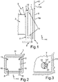
- a microwave cooking appliance 1 is shown in a schematic horizontal sectional view.
- the microwave cooking appliance 1 comprises a cooking chamber 2, which is delimited by walls of a muffle 3. Front side and thus facing a user, the muffle has 3 a feed opening 4, through which food can be introduced into the cooking chamber 2.
- the loading opening 4 is closed at the front by a door 5, wherein in Fig. 1 the closed state is shown.
- the door 5 comprises a door panel 6 arranged on the outside or on the front, which door panel may for example be a viewing window.
- the door 5 comprises a support part 7, to which hinges 8 of the door 5 are coupled, so that the door 5 as a whole about an axis perpendicular to the Figurebene axis relative to the rest of the device and in particular thus to the muffle 3 and a housing, not shown 9 is pivotable.
- the support member 7 is preferably formed as a plate.
- a microwave shield 10 is arranged and fastened to the carrier part 7.
- the microwave shield 10 is spaced from a flange 11 of the muffle 3, wherein the flange 11 is in particular formed completely circumferential and thus represents the edge of the feed opening 4 and limits this.
- a device front 12 is shown, which is for example a control panel and is arranged on the housing 9. As in Fig. 1 can be seen, it is preferably provided that an outer side 12a of the device front 12 in the vertical direction and thus in the y direction is flush with an outer side 6a of the front panel 6 of the door 5.
- a distance d between the flange 11 and the microwave shield 10 is set so that the smallest possible leakage of microwave energy from the cooking chamber 2 passes to the outside during operation of the microwave cooking appliance 1.
- the Mikrowellengarêt 1 has an adjustment device 13 which is formed so that the microwave shield 10 in all three spatial directions (x-, y- and z-direction) relative to the flange 11 in the position adjustable and thus changeable.
- Fig. 2 is shown in a view to the cooking chamber 2 through the Mikrowellengar réelle 1, wherein the door 5 shown in the closed state is shown only with the support member 7 and the microwave shield 10.
- the adjusting device 13 comprises a plurality of, in the exemplary embodiment four holes 15 and 16 (two upper and two lower), which are formed in the respective corner regions of the quadrangular plate or the support member 7. Fastening elements, in particular screws, can be passed through these holes 15, 16 in order to fix the microwave shield 10 to the carrier part 7 so as to be non-destructively detachable. Through these holes 15, 16 with their execution explained in more detail below, a part of the adjustment device 13 is created in connection with the fastening elements, so that an adjustment of a relative position between the microwave shield 10 and the support member 7 in two mutually perpendicular spatial directions, namely the y - And the z-direction and thus can be done in a plane parallel to the support member 7.
- Fig. 2 Here, by way of example, a situation is shown in which the microwave shield 10 is arranged and fastened eccentrically to the dimensions and configurations of the carrier part 7. This is made possible by these specific subcomponents of the adjustment device 13, wherein by the in Fig. 2 shown advantageous position very specific requirements in terms of positional tolerances between the individual positions to be matched between the components is the most advantageous in terms of the lowest possible microwave energy output from the cooking chamber 2.
- Fig. 3 in the context of an enlarged view of the embodiment in Fig. 2 shown in the area of the hole 16. It can be seen that an inner diameter 14 'of the hole 16 is larger than an outer diameter 14 "of a fastening element 17 such that movement with play is possible. times, in particular at least 1.5 times, in particular by at least 2 times greater than the outer diameter 14 ". The same is true in the dimensional relationships between the holes 16 and the associated, each passed through fasteners. As a result, a Relativpositionsver selectedung is created, which can be done varied and finely adjusted in this level.
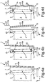
- Fig. 4a is a horizontal sectional view of an embodiment of the Mikrowellengarêts 1 is shown in which, for example, the support member 7 in a shown exaggerated manufacturing tolerance in width and / or in a tilted position.
- the attached thereto microwave shield 10 is arranged correspondingly inclined to the flange 11.
- the distances d in the upper and lower regions between the microwave shield 10 and the flange 11 are different. Therefore, a suboptimal position of the microwave shield 10 is present, so that a larger proportion of microwave energy could escape from the cooking chamber 2 during operation of the microwave cooking appliance 1.
- the adjusting device 13 as shown in FIG Fig. 4b a Abstandseinstell listening 18.
- the Abstandseinstell responded 18 is designed to set a relative position in a direction of depth and thus in the x direction of the Mikrowellengar réelles 1 dimensioned third spatial direction between the microwave shield 10 and the flange 11.
- the Abstandseinstell spur 18 has in the embodiment according to Fig. 4b a plurality of spacers 19 and 20. These are arranged in a free space 21 between the microwave shield 10 and the carrier part 7. By these spacers 19 and 20, the distance in this third spatial direction is adjusted so that the microwave shield 10 is arranged in a circumferentially about the flange 11 as far as possible the same distance d.
- the microwave shield 10 thus preferably extends in a plane parallel to the flange 11.
- Fig. 4c is a horizontal sectional view shown in which a front panel 6 of the door 5 is arranged inclined to the aperture 12.
- the spacer elements 19 and 20, as they are then in Fig. 4d are shown, designed multifunctional. It can thus be achieved with these spacers 19 and 20, which are merely exemplary in number, a diverse adjustment between different components and thus achieve a circumferential relative position adjustment between different components.
- a fastening element 17, which is to be used and used as an example for different embodiments of a fastening element, is arranged interlocking with a spacer element 19, and these two separate parts are positioned axially one inside the other.
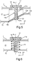
- a related first embodiment is shown in a sectional view in Fig. 5 shown.
- a longitudinal axis A of the fastening element 17 extends in the direction of this third spatial direction and thus in the x-direction. Accordingly, the longitudinal extent and thus longitudinal axis of the spacer element 19 can be seen.
- the spacer element 19 extends completely in the free space 21 and does not extend beyond it.
- the fastening element 17 is designed here as a screw which extends with a screw pin 17a, which preferably has the outer diameter 14 ", through the through-hole 16, which preferably has the inner diameter 14 '.
- the spacer element 19 has a continuous bore 19a, through which the screw pin 17a extends completely.
- the spacing element 19 comprises a wedge shape at an end 19b of its longitudinal extent dimensioned in the third spatial direction, wherein the spacing element 19 of this bevel and thus of this wedge shape rests against a slope 10a of an inside 10b of the microwave shield 10.
- the screw, which constitutes the fastening element 70, has at its front end of the screw pin 17a a thread 17b, which engages in a mating thread 22 in the bevel 20a and thus a mechanical coupling can be effected.
- Fig. 6 is in an alternative embodiment, the spacer element 19 formed as a spiral spring, which is also disposed completely within the free space 21.
- the microwave shield 10 in the region of the mechanical coupling with the fastening element 17 also has no bevel 10a.
- this spiral spring, which is the spacer element 19 in the direction of the longitudinal axis A is continuously variable in length, and an individual change in distance in the third spatial direction and thus in the x-direction between the support member 7 and the microwave shield 10 can take place.
- the corresponding geometry of the hole 16 is analogous to the embodiment and the explanations to FIGS. 2 and 3 as well Fig. 5 , so that also here an individual relative position setting in all three spatial directions is possible.
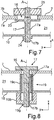
- Fig. 7 is shown in a further embodiment, a sectional view, in which the fastening element 17 and the spacer element 19 are integrated in a component.
- the fastener 17 is designed as a kind of screw, which includes a thread 17b.
- This is formed with a pin-like base or a screw pin 17a, at one end of which is formed as a thread 17b anchoring area for mounting in the microwave shield 10 is present.
- a plate-shaped and around the base or the screw pin 17a at least partially encircling collar 23 is formed. This collar 23 is supported on a side facing the microwave shield 10 inside 7a of the support member 7 in the assembled state.
- a distance in this third spatial direction between the microwave shield 10 and the carrier part 7 is adjustable depending on the relative position of the anchoring region or the thread 17b in a receptacle 24 in the microwave shield 10.
- the spacing adjustment can be carried out in this third spatial direction and thus in the x-direction.
- the fastening element 17 on an opposite end of the thread 17b has a coupling region 17c, which for Pairing with a fixing element 25 is formed.
- the coupling region 17c is designed as a thread and the fixing element designed as a nut.
- the fixing element 25 is located on an outer side 7b of the carrier part 7 facing away from the microwave shield 10. The adjusted relative position in the x-direction between the carrier part 7 and the microwave shield 10 is then fixed.
- Fig. 8 is shown in a further embodiment, a sectional view in which a multi-part spacer element 19 is provided.
- a first sub-element 19g extends outside of the free space 21 and on the side facing away from the carrier plate 7 of the microwave shield 10.
- the first sub-element 19g is non-destructive releasably connected to the microwave shield 10, in particular screwed therein. However, it may also be non-destructively non-destructive, for example, be pressed or welded or glued therein.
- a second sub-element 19c of the spacer element 19 extends substantially in the free space 21 and is connected to the second sub-element 19c such that these two sub-elements 19g and 19c can move in the direction of the axis A and thus also in the direction of the third spatial direction in a positionally variable manner.
- the second sub-element 19c has at its end facing the first sub-element 19g an external thread with which it can be coupled and screwed with an internal thread of the first sub-element 19g.
- the fastening element 17, in particular a screw in turn extends through a bore through the two partial elements 19g and 19c and is anchored in a receiving region 19d of the first partial element 19g, in particular screwed.
- the fastening element 17 in particular a screw
- the fastening element 17 extends through a bore through the two partial elements 19g and 19c and is anchored in a receiving region 19d of the first partial element 19g, in particular screwed.
- the fastening element 17, in particular a screw in turn extends through a bore through the two partial elements 19g and 19c and is anchored in a receiving region 19d of the first partial element 19g, in particular screwed.
- the fastening element 17 in particular a screw
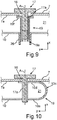
- Fig. 9 is shown in a further embodiment, a sectional view in which the spacer element 19 is formed dowel-like.
- the spacer element 19 comprises an expandable front end 19e, which engages or is inserted into a receptacle 26 in the microwave shield 10.
- a collar 19f is formed, which is supported on the inner side 7a of the carrier part 7.
- the fastener 17 with the pin 17a is passed axially through the spacer element 19 inside.
- the distance in the x-direction is adjustable. This then set distance can be fixed by the fastener 17 is displaced in the axial direction relative to the spacer element 19 in this and thereby the front end 19e is spread and wedged in the receptacle 26.
- the second sub-element 19c is fixed with an external thread on the microwave shield 10 and additionally carries the thread for the fastening element 17.
- the first sub-element 19g then has only an internal thread for the second sub-element 19c and a through hole for the fastening element 17.
- Fig. 10 is shown in a further sectional view of an embodiment in which the microwave shield 10 has an integrated spacer element 19, wherein this is formed by a bent free end or an edge.
- this edge is formed as a U-shaped bent tab 10c.
- Both legs 10d and 10e of the U-shape are connected to the fastening element 17 or this extends in the third spatial direction and thus in the x-direction through the two legs 10d and 10e.
- the two legs 10d and 10e can deform in the x-direction and thus can move towards each other or move away from each other, a change in the distance of the Microwave plate 10 are set to the support member 7 in this third spatial direction and fixed by the fastener 17.
- the leg 10d is formed with a cut thread into which the fastening element 17 engages. As soon as during mounting the fastening element 17 and in particular the screw then meets the second leg 10e, it cuts a further thread into it.
- the fastening element 17 By this self-tapping configuration of the fastening element 17, the position of the previously bent tab is fixed. The clamping of the support member 7 takes place at the end of the tab.
Landscapes
- Physics & Mathematics (AREA)
- Electromagnetism (AREA)
- Constitution Of High-Frequency Heating (AREA)
- Electric Ovens (AREA)
Priority Applications (1)
| Application Number | Priority Date | Filing Date | Title |
|---|---|---|---|
| PL15157384T PL2922367T3 (pl) | 2014-03-19 | 2015-03-03 | Urządzenie mikrofalowe do gotowania z urządzeniem regulacyjnym do regulacji ekranu mikrofalowego |
Applications Claiming Priority (2)
| Application Number | Priority Date | Filing Date | Title |
|---|---|---|---|
| DE102014205113 | 2014-03-19 | ||
| DE102014216557.1A DE102014216557A1 (de) | 2014-03-19 | 2014-08-20 | Mikrowellengargerät mit einer Justagevorrichtung zur Justage eines Mikrowellenschilds |
Publications (2)
| Publication Number | Publication Date |
|---|---|
| EP2922367A1 EP2922367A1 (de) | 2015-09-23 |
| EP2922367B1 true EP2922367B1 (de) | 2018-10-24 |
Family
ID=52627045
Family Applications (1)
| Application Number | Title | Priority Date | Filing Date |
|---|---|---|---|
| EP15157384.7A Active EP2922367B1 (de) | 2014-03-19 | 2015-03-03 | Mikrowellengargerät mit einer Justagevorrichtung zur Justage eines Mikrowellenschilds |
Country Status (6)
| Country | Link |
|---|---|
| US (2) | US10021740B2 (pl) |
| EP (1) | EP2922367B1 (pl) |
| DE (1) | DE102014216557A1 (pl) |
| ES (1) | ES2701856T3 (pl) |
| PL (1) | PL2922367T3 (pl) |
| TR (1) | TR201816603T4 (pl) |
Families Citing this family (2)
| Publication number | Priority date | Publication date | Assignee | Title |
|---|---|---|---|---|
| DE102014109729B3 (de) * | 2014-07-11 | 2015-08-20 | Miele & Cie. Kg | Gargerät und Befestigungssystem |
| CN116085839A (zh) * | 2021-11-05 | 2023-05-09 | 广东美的厨房电器制造有限公司 | 炉门组件和微波炉 |
Family Cites Families (10)
| Publication number | Priority date | Publication date | Assignee | Title |
|---|---|---|---|---|
| US3329795A (en) * | 1964-08-28 | 1967-07-04 | Gen Motors Corp | Microwave oven |
| BE791916A (fr) * | 1971-11-30 | 1973-03-16 | Raytheon Co | Appareil de chauffage par energie a haute-frequence |
| US4371770A (en) * | 1980-10-27 | 1983-02-01 | Raytheon Company | Adjustable microwave oven door seal |
| DE3130311A1 (de) * | 1981-07-31 | 1983-02-17 | Licentia Patent-Verwaltungs-Gmbh, 6000 Frankfurt | Tuer zum verschliessen des garraumes eines mikrowellenofens |
| DE3409563A1 (de) * | 1984-03-15 | 1985-09-19 | Bosch-Siemens Hausgeräte GmbH, 7000 Stuttgart | Mikrowellenofen |
| JPS63224182A (ja) * | 1987-03-11 | 1988-09-19 | 三洋電機株式会社 | 高周波加熱装置 |
| JPH09250760A (ja) * | 1996-03-18 | 1997-09-22 | Sharp Corp | 高周波加熱装置 |
| JP2003109745A (ja) * | 2001-09-28 | 2003-04-11 | Matsushita Electric Ind Co Ltd | 高周波加熱装置 |
| EP1401244B1 (en) | 2002-09-23 | 2011-02-16 | LG Electronics, Inc. | Constructional features in a microwave oven |
| DE102004048000A1 (de) | 2004-10-01 | 2006-04-06 | BSH Bosch und Siemens Hausgeräte GmbH | Verfahren zur Positionierung und Arretierung einer drehbar gelagerten Ofentür eines Mikrowellenofens sowie Mikrowellenofen |
-
2014
- 2014-08-20 DE DE102014216557.1A patent/DE102014216557A1/de not_active Withdrawn
-
2015
- 2015-03-03 EP EP15157384.7A patent/EP2922367B1/de active Active
- 2015-03-03 TR TR2018/16603T patent/TR201816603T4/tr unknown
- 2015-03-03 PL PL15157384T patent/PL2922367T3/pl unknown
- 2015-03-03 ES ES15157384T patent/ES2701856T3/es active Active
- 2015-03-04 US US14/637,419 patent/US10021740B2/en active Active
-
2018
- 2018-06-05 US US15/997,733 patent/US10986706B2/en active Active
Non-Patent Citations (1)
| Title |
|---|
| None * |
Also Published As
| Publication number | Publication date |
|---|---|
| EP2922367A1 (de) | 2015-09-23 |
| US10021740B2 (en) | 2018-07-10 |
| US20180288838A1 (en) | 2018-10-04 |
| TR201816603T4 (tr) | 2018-11-21 |
| DE102014216557A1 (de) | 2015-09-24 |
| US20150271878A1 (en) | 2015-09-24 |
| US10986706B2 (en) | 2021-04-20 |
| ES2701856T3 (es) | 2019-02-26 |
| PL2922367T3 (pl) | 2019-03-29 |
Similar Documents
| Publication | Publication Date | Title |
|---|---|---|
| EP3698055B1 (de) | Toleranzausgleichsanordnung | |
| EP2217469B1 (de) | Verstellelement | |
| DE102009059007B4 (de) | Vorrichtung zur lösbaren Befestigung eines Stromleiters an einem Stromwandlergehäuse | |
| DE102009025890A1 (de) | Vorrichtung zur Befestigung einer Frontblende an einer Seitenzarge eines beweglichen Möbelteils eines Möbels, Schubkasten und Möbel | |
| EP3625417B1 (de) | In seiner länge einstellbarer steuerarm | |
| EP2382905A2 (de) | Hohlprofil | |
| EP0643270A2 (de) | Anordnung zur Halterung eines Einbaukochfeldes | |
| AT519900B1 (de) | Möbelantrieb | |
| EP1975518A2 (de) | Vorrichtung zum Anordnen eines Heizkörpers | |
| EP3666126B1 (de) | Schubladen-verbindungsvorrichtung für eine verbindung einer schubladenfront mit einem schubladenseitenteil | |
| EP1856417B1 (de) | Hochlastbeschlag zum verbinden von zwei bauteilen | |
| DE2721625C2 (pl) | ||
| EP2922367B1 (de) | Mikrowellengargerät mit einer Justagevorrichtung zur Justage eines Mikrowellenschilds | |
| EP2873874B1 (de) | Anordnung zur Befestigung eines Ausstattungsteiles eines Kraftfahrzeuges | |
| EP3608588B1 (de) | Haltefeder für leuchte | |
| DE4219481A1 (de) | Vorrichtung zum Einstellen eines ersten Bauteiles relativ zu einem zweiten Bauteil | |
| DE102008057397B4 (de) | Linearführung | |
| EP0931885A2 (de) | Entwässerungsrinne | |
| EP1462049B1 (de) | Befestigungsvorrichtung für eine Arbeitsplatte | |
| EP3260713B1 (de) | Schnellbefestigungsvorrichtung des typs schraube-mutter, insbesondere für die befestigung von einem rahmen an einer unterflur-versorgungseinheit | |
| WO2013026683A1 (de) | Vorrichtung zur koppelung eines schubkastens mit einer laufschiene einer auszugsführung | |
| EP3666124A1 (de) | Seitenzargenverstellvorrichtung zur seitlichen verstellung einer schubladenfront relativ zu einer seitenzarge | |
| EP1454026A1 (de) | Montageplatte zur verstellbaren halterung von möbelscharnieren am korpus von möbelstücken | |
| EP1645211A2 (de) | Stabilisierungsvorrichtung für Möbelteile | |
| WO2013041375A1 (de) | Tür für ein haushaltsgerät sowie haushaltsgerät, insbesondere gargerät |
Legal Events
| Date | Code | Title | Description |
|---|---|---|---|
| PUAI | Public reference made under article 153(3) epc to a published international application that has entered the european phase |
Free format text: ORIGINAL CODE: 0009012 |
|
| AK | Designated contracting states |
Kind code of ref document: A1 Designated state(s): AL AT BE BG CH CY CZ DE DK EE ES FI FR GB GR HR HU IE IS IT LI LT LU LV MC MK MT NL NO PL PT RO RS SE SI SK SM TR |
|
| AX | Request for extension of the european patent |
Extension state: BA ME |
|
| 17P | Request for examination filed |
Effective date: 20160323 |
|
| RBV | Designated contracting states (corrected) |
Designated state(s): AL AT BE BG CH CY CZ DE DK EE ES FI FR GB GR HR HU IE IS IT LI LT LU LV MC MK MT NL NO PL PT RO RS SE SI SK SM TR |
|
| GRAP | Despatch of communication of intention to grant a patent |
Free format text: ORIGINAL CODE: EPIDOSNIGR1 |
|
| STAA | Information on the status of an ep patent application or granted ep patent |
Free format text: STATUS: GRANT OF PATENT IS INTENDED |
|
| INTG | Intention to grant announced |
Effective date: 20180606 |
|
| GRAS | Grant fee paid |
Free format text: ORIGINAL CODE: EPIDOSNIGR3 |
|
| GRAA | (expected) grant |
Free format text: ORIGINAL CODE: 0009210 |
|
| STAA | Information on the status of an ep patent application or granted ep patent |
Free format text: STATUS: THE PATENT HAS BEEN GRANTED |
|
| AK | Designated contracting states |
Kind code of ref document: B1 Designated state(s): AL AT BE BG CH CY CZ DE DK EE ES FI FR GB GR HR HU IE IS IT LI LT LU LV MC MK MT NL NO PL PT RO RS SE SI SK SM TR |
|
| REG | Reference to a national code |
Ref country code: CH Ref legal event code: EP |
|
| REG | Reference to a national code |
Ref country code: IE Ref legal event code: FG4D Free format text: LANGUAGE OF EP DOCUMENT: GERMAN |
|
| REG | Reference to a national code |
Ref country code: AT Ref legal event code: REF Ref document number: 1058236 Country of ref document: AT Kind code of ref document: T Effective date: 20181115 |
|
| REG | Reference to a national code |
Ref country code: DE Ref legal event code: R096 Ref document number: 502015006545 Country of ref document: DE |
|
| REG | Reference to a national code |
Ref country code: NL Ref legal event code: FP |
|
| REG | Reference to a national code |
Ref country code: ES Ref legal event code: FG2A Ref document number: 2701856 Country of ref document: ES Kind code of ref document: T3 Effective date: 20190226 |
|
| REG | Reference to a national code |
Ref country code: LT Ref legal event code: MG4D |
|
| PG25 | Lapsed in a contracting state [announced via postgrant information from national office to epo] |
Ref country code: FI Free format text: LAPSE BECAUSE OF FAILURE TO SUBMIT A TRANSLATION OF THE DESCRIPTION OR TO PAY THE FEE WITHIN THE PRESCRIBED TIME-LIMIT Effective date: 20181024 Ref country code: LV Free format text: LAPSE BECAUSE OF FAILURE TO SUBMIT A TRANSLATION OF THE DESCRIPTION OR TO PAY THE FEE WITHIN THE PRESCRIBED TIME-LIMIT Effective date: 20181024 Ref country code: HR Free format text: LAPSE BECAUSE OF FAILURE TO SUBMIT A TRANSLATION OF THE DESCRIPTION OR TO PAY THE FEE WITHIN THE PRESCRIBED TIME-LIMIT Effective date: 20181024 Ref country code: IS Free format text: LAPSE BECAUSE OF FAILURE TO SUBMIT A TRANSLATION OF THE DESCRIPTION OR TO PAY THE FEE WITHIN THE PRESCRIBED TIME-LIMIT Effective date: 20190224 Ref country code: NO Free format text: LAPSE BECAUSE OF FAILURE TO SUBMIT A TRANSLATION OF THE DESCRIPTION OR TO PAY THE FEE WITHIN THE PRESCRIBED TIME-LIMIT Effective date: 20190124 Ref country code: BG Free format text: LAPSE BECAUSE OF FAILURE TO SUBMIT A TRANSLATION OF THE DESCRIPTION OR TO PAY THE FEE WITHIN THE PRESCRIBED TIME-LIMIT Effective date: 20190124 Ref country code: LT Free format text: LAPSE BECAUSE OF FAILURE TO SUBMIT A TRANSLATION OF THE DESCRIPTION OR TO PAY THE FEE WITHIN THE PRESCRIBED TIME-LIMIT Effective date: 20181024 |
|
| PG25 | Lapsed in a contracting state [announced via postgrant information from national office to epo] |
Ref country code: AL Free format text: LAPSE BECAUSE OF FAILURE TO SUBMIT A TRANSLATION OF THE DESCRIPTION OR TO PAY THE FEE WITHIN THE PRESCRIBED TIME-LIMIT Effective date: 20181024 Ref country code: PT Free format text: LAPSE BECAUSE OF FAILURE TO SUBMIT A TRANSLATION OF THE DESCRIPTION OR TO PAY THE FEE WITHIN THE PRESCRIBED TIME-LIMIT Effective date: 20190224 Ref country code: GR Free format text: LAPSE BECAUSE OF FAILURE TO SUBMIT A TRANSLATION OF THE DESCRIPTION OR TO PAY THE FEE WITHIN THE PRESCRIBED TIME-LIMIT Effective date: 20190125 Ref country code: SE Free format text: LAPSE BECAUSE OF FAILURE TO SUBMIT A TRANSLATION OF THE DESCRIPTION OR TO PAY THE FEE WITHIN THE PRESCRIBED TIME-LIMIT Effective date: 20181024 Ref country code: RS Free format text: LAPSE BECAUSE OF FAILURE TO SUBMIT A TRANSLATION OF THE DESCRIPTION OR TO PAY THE FEE WITHIN THE PRESCRIBED TIME-LIMIT Effective date: 20181024 |
|
| REG | Reference to a national code |
Ref country code: DE Ref legal event code: R097 Ref document number: 502015006545 Country of ref document: DE |
|
| PG25 | Lapsed in a contracting state [announced via postgrant information from national office to epo] |
Ref country code: CZ Free format text: LAPSE BECAUSE OF FAILURE TO SUBMIT A TRANSLATION OF THE DESCRIPTION OR TO PAY THE FEE WITHIN THE PRESCRIBED TIME-LIMIT Effective date: 20181024 Ref country code: DK Free format text: LAPSE BECAUSE OF FAILURE TO SUBMIT A TRANSLATION OF THE DESCRIPTION OR TO PAY THE FEE WITHIN THE PRESCRIBED TIME-LIMIT Effective date: 20181024 |
|
| PG25 | Lapsed in a contracting state [announced via postgrant information from national office to epo] |
Ref country code: EE Free format text: LAPSE BECAUSE OF FAILURE TO SUBMIT A TRANSLATION OF THE DESCRIPTION OR TO PAY THE FEE WITHIN THE PRESCRIBED TIME-LIMIT Effective date: 20181024 Ref country code: SM Free format text: LAPSE BECAUSE OF FAILURE TO SUBMIT A TRANSLATION OF THE DESCRIPTION OR TO PAY THE FEE WITHIN THE PRESCRIBED TIME-LIMIT Effective date: 20181024 Ref country code: SK Free format text: LAPSE BECAUSE OF FAILURE TO SUBMIT A TRANSLATION OF THE DESCRIPTION OR TO PAY THE FEE WITHIN THE PRESCRIBED TIME-LIMIT Effective date: 20181024 Ref country code: RO Free format text: LAPSE BECAUSE OF FAILURE TO SUBMIT A TRANSLATION OF THE DESCRIPTION OR TO PAY THE FEE WITHIN THE PRESCRIBED TIME-LIMIT Effective date: 20181024 |
|
| PLBE | No opposition filed within time limit |
Free format text: ORIGINAL CODE: 0009261 |
|
| STAA | Information on the status of an ep patent application or granted ep patent |
Free format text: STATUS: NO OPPOSITION FILED WITHIN TIME LIMIT |
|
| 26N | No opposition filed |
Effective date: 20190725 |
|
| PG25 | Lapsed in a contracting state [announced via postgrant information from national office to epo] |
Ref country code: MC Free format text: LAPSE BECAUSE OF FAILURE TO SUBMIT A TRANSLATION OF THE DESCRIPTION OR TO PAY THE FEE WITHIN THE PRESCRIBED TIME-LIMIT Effective date: 20181024 Ref country code: SI Free format text: LAPSE BECAUSE OF FAILURE TO SUBMIT A TRANSLATION OF THE DESCRIPTION OR TO PAY THE FEE WITHIN THE PRESCRIBED TIME-LIMIT Effective date: 20181024 |
|
| REG | Reference to a national code |
Ref country code: CH Ref legal event code: PL |
|
| PG25 | Lapsed in a contracting state [announced via postgrant information from national office to epo] |
Ref country code: LU Free format text: LAPSE BECAUSE OF NON-PAYMENT OF DUE FEES Effective date: 20190303 |
|
| REG | Reference to a national code |
Ref country code: BE Ref legal event code: MM Effective date: 20190331 |
|
| PG25 | Lapsed in a contracting state [announced via postgrant information from national office to epo] |
Ref country code: IE Free format text: LAPSE BECAUSE OF NON-PAYMENT OF DUE FEES Effective date: 20190303 Ref country code: LI Free format text: LAPSE BECAUSE OF NON-PAYMENT OF DUE FEES Effective date: 20190331 Ref country code: CH Free format text: LAPSE BECAUSE OF NON-PAYMENT OF DUE FEES Effective date: 20190331 |
|
| PG25 | Lapsed in a contracting state [announced via postgrant information from national office to epo] |
Ref country code: BE Free format text: LAPSE BECAUSE OF NON-PAYMENT OF DUE FEES Effective date: 20190331 |
|
| PG25 | Lapsed in a contracting state [announced via postgrant information from national office to epo] |
Ref country code: MT Free format text: LAPSE BECAUSE OF FAILURE TO SUBMIT A TRANSLATION OF THE DESCRIPTION OR TO PAY THE FEE WITHIN THE PRESCRIBED TIME-LIMIT Effective date: 20181024 |
|
| REG | Reference to a national code |
Ref country code: AT Ref legal event code: MM01 Ref document number: 1058236 Country of ref document: AT Kind code of ref document: T Effective date: 20200303 |
|
| PG25 | Lapsed in a contracting state [announced via postgrant information from national office to epo] |
Ref country code: CY Free format text: LAPSE BECAUSE OF FAILURE TO SUBMIT A TRANSLATION OF THE DESCRIPTION OR TO PAY THE FEE WITHIN THE PRESCRIBED TIME-LIMIT Effective date: 20181024 |
|
| PG25 | Lapsed in a contracting state [announced via postgrant information from national office to epo] |
Ref country code: HU Free format text: LAPSE BECAUSE OF FAILURE TO SUBMIT A TRANSLATION OF THE DESCRIPTION OR TO PAY THE FEE WITHIN THE PRESCRIBED TIME-LIMIT; INVALID AB INITIO Effective date: 20150303 |
|
| PG25 | Lapsed in a contracting state [announced via postgrant information from national office to epo] |
Ref country code: AT Free format text: LAPSE BECAUSE OF NON-PAYMENT OF DUE FEES Effective date: 20200303 |
|
| PG25 | Lapsed in a contracting state [announced via postgrant information from national office to epo] |
Ref country code: MK Free format text: LAPSE BECAUSE OF FAILURE TO SUBMIT A TRANSLATION OF THE DESCRIPTION OR TO PAY THE FEE WITHIN THE PRESCRIBED TIME-LIMIT Effective date: 20181024 |
|
| PGFP | Annual fee paid to national office [announced via postgrant information from national office to epo] |
Ref country code: PL Payment date: 20250224 Year of fee payment: 11 |
|
| PGFP | Annual fee paid to national office [announced via postgrant information from national office to epo] |
Ref country code: ES Payment date: 20250416 Year of fee payment: 11 |
|
| PGFP | Annual fee paid to national office [announced via postgrant information from national office to epo] |
Ref country code: IT Payment date: 20250331 Year of fee payment: 11 |
|
| PGFP | Annual fee paid to national office [announced via postgrant information from national office to epo] |
Ref country code: GB Payment date: 20260324 Year of fee payment: 12 |
|
| PGFP | Annual fee paid to national office [announced via postgrant information from national office to epo] |
Ref country code: DE Payment date: 20260331 Year of fee payment: 12 |
|
| PGFP | Annual fee paid to national office [announced via postgrant information from national office to epo] |
Ref country code: NL Payment date: 20260323 Year of fee payment: 12 |
|
| PGFP | Annual fee paid to national office [announced via postgrant information from national office to epo] |
Ref country code: FR Payment date: 20260324 Year of fee payment: 12 |
|
| PGFP | Annual fee paid to national office [announced via postgrant information from national office to epo] |
Ref country code: TR Payment date: 20260225 Year of fee payment: 12 |