EP2921889A1 - Polarization-maintaining optical fiber - Google Patents
Polarization-maintaining optical fiber Download PDFInfo
- Publication number
- EP2921889A1 EP2921889A1 EP15156197.4A EP15156197A EP2921889A1 EP 2921889 A1 EP2921889 A1 EP 2921889A1 EP 15156197 A EP15156197 A EP 15156197A EP 2921889 A1 EP2921889 A1 EP 2921889A1
- Authority
- EP
- European Patent Office
- Prior art keywords
- polarization
- optical fiber
- maintaining optical
- cladding coat
- refractive index
- Prior art date
- Legal status (The legal status is an assumption and is not a legal conclusion. Google has not performed a legal analysis and makes no representation as to the accuracy of the status listed.)
- Granted
Links
Images


Classifications
-
- G—PHYSICS
- G02—OPTICS
- G02B—OPTICAL ELEMENTS, SYSTEMS OR APPARATUS
- G02B6/00—Light guides; Structural details of arrangements comprising light guides and other optical elements, e.g. couplings
- G02B6/02—Optical fibres with cladding with or without a coating
- G02B6/024—Optical fibres with cladding with or without a coating with polarisation maintaining properties
-
- G—PHYSICS
- G02—OPTICS
- G02B—OPTICAL ELEMENTS, SYSTEMS OR APPARATUS
- G02B6/00—Light guides; Structural details of arrangements comprising light guides and other optical elements, e.g. couplings
- G02B6/02—Optical fibres with cladding with or without a coating
- G02B6/036—Optical fibres with cladding with or without a coating core or cladding comprising multiple layers
- G02B6/03616—Optical fibres characterised both by the number of different refractive index layers around the central core segment, i.e. around the innermost high index core layer, and their relative refractive index difference
- G02B6/03638—Optical fibres characterised both by the number of different refractive index layers around the central core segment, i.e. around the innermost high index core layer, and their relative refractive index difference having 3 layers only
- G02B6/0365—Optical fibres characterised both by the number of different refractive index layers around the central core segment, i.e. around the innermost high index core layer, and their relative refractive index difference having 3 layers only arranged - - +
-
- C—CHEMISTRY; METALLURGY
- C03—GLASS; MINERAL OR SLAG WOOL
- C03B—MANUFACTURE, SHAPING, OR SUPPLEMENTARY PROCESSES
- C03B2203/00—Fibre product details, e.g. structure, shape
- C03B2203/10—Internal structure or shape details
- C03B2203/22—Radial profile of refractive index, composition or softening point
-
- C—CHEMISTRY; METALLURGY
- C03—GLASS; MINERAL OR SLAG WOOL
- C03B—MANUFACTURE, SHAPING, OR SUPPLEMENTARY PROCESSES
- C03B2203/00—Fibre product details, e.g. structure, shape
- C03B2203/30—Polarisation maintaining [PM], i.e. birefringent products, e.g. with elliptical core, by use of stress rods, "PANDA" type fibres
Definitions
- the present invention relates to a polarization-maintaining optical fiber.
- a polarization-maintaining optical fiber is used to, for example, connect optical devices each other having polarization dependence in an optical transmission system or the like.
- a polarization-maintaining optical fiber which includes: a pair of stress-applying parts provided at both sides of a core; and a cladding surrounding the core and the paired stress-applying parts.
- a polarization-maintaining photonic crystal fiber is also known in which a plurality of air holes around a core area are formed ( Katsuhiro Takenaga, et. al, "Broadband Polarization-Maintaining Photonic Crystal Fiber", Technical Report by Fujikura Ltd., April, 2005, 108th, p6-9 , hereinafter, refer to Non-Patent Document 1).
- a difference in a mode field diameter between the above-mentioned polarization-maintaining optical fiber and an existing optical fiber optically connected thereto increases and a connection loss between the above-mentioned polarization-maintaining optical fiber and the existing optical fiber thereby increases.
- Non-Patent Document 1 it is possible to reduce an increase in a bending loss or polarization crosstalk when the optical fiber is bent so as to have a small radius while setting the mode field diameter large; however, it is difficult to manufacture the polarization-maintaining photonic crystal fiber and it is also difficult to reduce the manufacturing cost.
- the invention was conceived in view of the above-described circumstances and has an object thereof to provide a polarization-maintaining optical fiber which can make the mode field diameter thereof large while reducing an increase in a bending loss and polarization crosstalk even where the fiber is bent so as to have a small radius and furthermore can be easily and inexpensively manufactured.
- a polarization-maintaining optical fiber includes: a core; a pair of stress-applying parts disposed at both sides of the core at a distance; and a cladding coat that surrounds the core and the paired stress-applying parts, wherein the cladding coat includes: a first cladding coat disposed around the core; a second cladding coat disposed around the first cladding coat; and a third cladding coat disposed around the second cladding coat, and wherein a maximum refractive index of the core is greater than each of maximum refractive indexes of the first cladding coat, the second cladding coat, and the third cladding coat, a maximum refractive index of the second cladding coat is lower than each of maximum refractive indexes of the first cladding coat and the third cladding coat, a coefficient of thermal expansion of each of stress-applying parts is greater than a coefficient of thermal expansion
- a refractive index profile with respect to the radial direction of the polarization-maintaining optical fiber has a trench shape (trench profile).
- the polarization-maintaining optical fiber it is possible to reduce a bending loss of the optical fiber without reducing the mode field diameter when the optical fiber is bent so as to have a small radius.
- a pair of stress-applying parts that apply a stress to the core and thereby apply birefringence thereto are provided in the polarization-maintaining optical fiber according to the aspect of the invention.
- the distance between the paired stress-applying parts is narrow so that each stress-applying part cuts at least the second cladding coat and it is possible to reduce an increase in polarization crosstalk (bending polarization crosstalk) which is generated when the optical fiber is bent so as to have a small radius.
- polarization crosstalk bending polarization crosstalk
- the stress-applying part may be provided to protrude from a boundary between the first cladding coat and the second cladding coat in a radial-inner direction.
- a value of r2/rl is in a range of 2.5 to 4.5.
- a relative refractive index difference of the core with reference to the maximum refractive index of the third cladding coat is in a range of 0.20% to 0.70%.
- a radius with reference to a center of the core is represented as r
- a relative refractive index difference in the radius r with reference to the maximum refractive index of the third cladding coat is represented as ⁇ n (r) and a radius of an inner edge of the second cladding coat is represented as r3
- a refractive index volume V of the second cladding coat expressed by the following numerical expression (1) is in a range of 25% ⁇ m 2 to 110% ⁇ m 2 .
- a diameter of each stress-applying part is in a range of 30 to 40 ( ⁇ m, and a distance between the paired stress-applying parts is less than or equal to 20 ⁇ m. (Expression 1)
- V 2 ⁇ ⁇ r ⁇ 2 r ⁇ 3 ⁇ n r ⁇ rdr
- the refractive index volume V of the second cladding coat may be greater than or equal to 50% ⁇ m 2 .
- a relative refractive index difference of the first cladding coat with reference to the maximum refractive index of the third cladding coat may be in a range of -0.10% to 0.05%.
- a relative refractive index difference of the second cladding coat with reference to the maximum refractive index of the third cladding coat may be in a range of -0.60% to -0.20%.
- a cut-off wavelength of the polarization-maintaining optical fiber may be less than or equal to 1.44 ⁇ m
- a mode field diameter of the polarization-maintaining optical fiber in an operating wavelength of 1.55 ⁇ m may be greater than or equal to 7.9 ⁇ m
- the polarization-maintaining optical fiber may propagate light having an operating wavelength of up to 1.65 ⁇ m in a single-mode
- the measurement value of the bending loss may be less than or equal to 0.05dB
- the measurement value of the polarization crosstalk thereof may be less than or equal to -30dB.
- a cut-off wavelength of the polarization-maintaining optical fiber may be less than or equal to 1.30 ⁇ m
- the polarization-maintaining optical fiber may propagate light having an operating wavelength of 1.31 ⁇ m in a single-mode
- a mode field diameter of the polarization-maintaining optical fiber in an operating wavelength of 1.31 ⁇ m is greater than or equal to 6.6 ⁇ m
- the measurement value of the bending loss may be less than or equal to 0.05dB
- the measurement value of the polarization crosstalk thereof is less than or equal to -30dB.
- a cut-off wavelength of the polarization-maintaining optical fiber may be less than or equal to 0.97 ⁇ m
- the polarization-maintaining optical fiber may propagate light having an operating wavelength of 0.98 ⁇ m in a single-mode
- a mode field diameter of the polarization-maintaining optical fiber in an operating wavelength of 0.98 ⁇ m may be greater than or equal to 4.7 ⁇ m
- the measurement value of the bending loss may be less than or equal to 0.05dB
- the measurement value of the polarization crosstalk thereof is less than or equal to -30dB.
- a cut-off wavelength of the polarization-maintaining optical fiber may be less than or equal to 0.84 ⁇ m
- the polarization-maintaining optical fiber may propagate light having an operating wavelength of 0.85 ⁇ m in a single-mode
- a mode field diameter of the polarization-maintaining optical fiber in an operating wavelength of 0.85 ⁇ m may be greater than or equal to 3.9 ⁇ m
- the measurement value of the bending loss may be less than or equal to 0.05dB
- the measurement value of the polarization crosstalk thereof is less than or equal to -30dB.
- the polarization-maintaining optical fiber by which the mode field diameter can be large while preventing an increase in a bending loss and polarization crosstalk even in a state of being bent so as to have a small radius.
- the mode field diameter can be large, it is possible to reduce and lower a connection loss between the polarization-maintaining optical fiber and the existing optical fiber.
- the polarization-maintaining optical fiber that can be produced easier than and cheaper than a polarization-maintaining photonic crystal fiber.
- FIGS. 1 to 6 a polarization-maintaining optical fiber according to one of embodiments of the invention will be described with reference to FIGS. 1 to 6 .
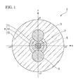
- a polarization-maintaining optical fiber 1 includes: a core 2 having a radius of r1; a pair of stress-applying parts 3 that are disposed at both sides of the core 2 at a distance; and a cladding coat 4 that surrounds the core 2 and the paired stress-applying parts 3.
- the cladding coat 4 includes: a first cladding coat 11 that has a radius r2 and is disposed around the core 21; a second cladding coat 12 that has a radius r3 and is disposed around the first cladding coat 11; and a third cladding coat 13 that has a radius r4 and is disposed around the second cladding coat 12.
- the maximum refractive index of the core 2 is greater than each of the maximum refractive indexes of the above-described first cladding coat 11, second cladding coat 12, and third cladding coat 13.
- the maximum refractive index of the second cladding coat 12 is lower than the maximum refractive indexes of the first cladding coat 11 and the third cladding coat 13.
- the maximum refractive index in the region in the radial direction from the center of the core 2 to the outer edge thereof is defined as the maximum refractive index of the core 2; the maximum refractive index in the region in the radial direction from the inner edge of the first cladding coat 11 to the outer edge thereof is defined as the maximum refractive index of the first cladding coat 11; the maximum refractive index in the region in the radial direction from the inner edge of the second cladding coat 12 to the outer edge thereof is defined as the maximum refractive index of the second cladding coat 12; and the maximum refractive index in the region in the radial direction from the inner edge of the third cladding coat 13 to the outer edge thereof is defined as the maximum refractive index of the third cladding coat 13.
- the refractive index is the maximum refractive indexes of the core 2; since the refractive indexes of the first cladding coat 11 are constant regardless of positions thereof in the radial direction, the refractive index is the maximum refractive index of the first cladding coat 11; since the refractive indexes of the second cladding coat 12 are constant regardless of positions thereof in the radial direction, the refractive index is the maximum refractive index of the second cladding coat 12; and since the refractive indexes of the third cladding coat 13 are constant regardless of positions thereof in the radial direction, the refractive index is the maximum refractive index of the third cladding coat 13.
- the cladding coat 4 is configured so that the second cladding coat 12 having the refractive index lower than those of the first cladding coat 11 and the third cladding coat 13 is provided between the first cladding coat 11 and the third cladding coat 13, and the polarization-maintaining optical fiber 1 according to the embodiment thereby has a refractive index profile (refractive index profile) with respect to the radial direction of the polarization-maintaining optical fiber 1 that has a profile having a trench shape (trench profile) as shown in FIG. 2 .
- a diameter of the mode field 5 (hereinbelow, referred to as a mode field diameter) can be larger as shown in FIG. 1 .
- a difference between the effective refractive index on the outer edge of the mode field 5 and the refractive index of the second cladding coat 12 can be larger. Therefore, as compared with the case of using a conventional polarization-maintaining optical fiber (in which the cladding coat 4 is a single polarization-maintaining optical fiber) having a common single-peaked profile which does not has a trench shape, it is possible to reduce a bending loss when the optical fiber is bent so as to have a small radius.
- the polarization-maintaining optical fiber it is possible to reduce a bending loss of the optical fiber without reducing the mode field diameter when the optical fiber is bent so as to have a small radius.
- mode field diameter is represented by reference letter "MFD" in FIGS. 2 and 3 .
- the paired stress-applying parts 3 apply a stress to the core 2 and thereby apply birefringence thereto.
- each stress-applying part 3 is formed in a circular cross section.
- each stress-applying part 3 is higher than the coefficient of thermal expansion of the cladding coat 4.
- the stress-applying parts 3 is provided to cut the second cladding coat 12 at the position in a circumferential direction (at the position of the second cladding coat 12 in the circumferential direction of the second cladding coat 12).
- the stress-applying parts 3 cut the second cladding coat 12 so that the stress-applying parts 3 sandwich the first cladding coat 11, and two second cladding coats 12 are thereby formed in an arc-shape on the first cladding coat 11 in the circumferential direction of the first cladding coat 11.
- the center of the core 2, the center of the first cladding coat 11, the center of the second cladding coat 12 (the center of the virtual circle forming the arc-shape of two second cladding coats 12), and the two centers of the stress-applying parts 3 are positioned on the same line (on the line extending in the y-axial direction shown in FIG. 1 ).
- each stress-applying part 3 is provided to protrude in the radial-inner direction from the boundary between the first cladding coat 11 and the second cladding coat 12; however, for example, the stress-applying part 3 may be provided so as not to protrude in the radial-inner direction from the boundary between the first cladding coat 11 and the second cladding coat 12.
- each stress-applying part 3 is provided to protrude in the radial-outer direction from the boundary between the second cladding coat 12 and the third cladding coat 13.
- the maximum refractive index of each stress-applying part 3 is lower than the maximum refractive indexes of the first cladding coat 11 and the third cladding coat 13.
- the maximum refractive index of each stress-applying part 3 is lower than the maximum refractive index of the second cladding coat 12.
- the maximum refractive index in the region in the radial direction from the center of each stress-applying part 3 to the outer edge thereof is defined as the above-described maximum refractive index of each stress-applying part 3.
- the refractive index is the maximum refractive index of the stress-applying part 3.
- the gap r5 between the paired stress-applying parts 3 is narrow to the extent that each stress-applying part 3 cuts the second cladding coat 12, and it is possible to reduce an increase in polarization crosstalk (bending polarization crosstalk) which is generated when the optical fiber is bent so as to have a small radius.
- polarization crosstalk bending polarization crosstalk
- any materials are optionally selected and used as long as such materials are used to form a polarization-maintaining optical fiber (PANDA polarization-maintaining optical fiber) including the paired stress-applying parts 3.
- PANDA polarization-maintaining optical fiber polarization-maintaining optical fiber
- silica into which GeO2 is doped may be used as the core 2
- pure silica may be used as the first cladding coat 11 and the third cladding coat 13
- silica into which fluorine is doped may be used as the second cladding coat 12
- silica into which boron is doped may be used as each stress-applying part 3.
- the value of r2/r1 is preferably in a range of 2.5 to 4.5 and more preferably in a range of 3.0 to 4.5.
- the variation in mode field diameter is further reduced, and it is possible to further reduce and lower a bending loss of the optical fiber.
- the value of r2/r1 is less than or equal to 4.5. The reason is that, in the case where the r2/rl excessively increases, the optical characteristics, particularly, a cut-off wavelength of the optical fiber, which are due to change in relative refractive index difference of the first cladding coat 11 described later, significantly vary, and the manufacturability thereof is deteriorated.
- the relative refractive index difference of the first cladding coat 11 with reference to the maximum refractive index of the third cladding coat 13 is preferably in a range of -0.10% to 0.05% and more preferably in a range of -0.10% to 0.00%.
- the relative refractive index difference of the first cladding coat 11 is in the above-described range so that provisions of a desired cut-off wavelength and a desired mode field diameter and reduction in bending loss can be simultaneously realized.
- the relative refractive index difference in the case of the radius r with reference to the maximum refractive index of the third cladding coat 13 is represented by ⁇ n (r)
- the radius of the inner edge of the second cladding coat 12 (the radius of the first cladding coat 11) is represented by r2
- the radius of the outer edge of the second cladding coat 12 is represented by r3
- the refractive index volume V of the second cladding coat 12 is expressed by the following numerical expression (1). (Expression 1)
- V 2 ⁇ ⁇ r ⁇ 2 r ⁇ 3 ⁇ n r ⁇ rdr
- a polarization-maintaining optical fiber having a single-peaked profile and a mandrel having a predetermined diameter are prepared, the polarization-maintaining optical fiber having a single-peaked profile is wound around the mandrel ten times, that is, the number of windings thereof is 10, a bending loss in a predetermined wavelength is measured, and a value of increase in bending loss is obtained (reference value (A) of increase in bending loss).
- the polarization-maintaining optical fiber 1 according to the embodiment and the mandrel that is the same as the above-described mandrel are prepared, the polarization-maintaining optical fiber 1 is wound around the mandrel and the number of windings thereof is 10, a bending loss in the predetermined wavelength is measured by the same method described above, and a value of increase in bending loss is obtained (value (B) of increase in bending loss of the embodiment). Next, a bending loss ratio is determined which means the ratio of the value (B) of increase in bending loss of the embodiment to the reference value (A) of increase in bending loss in the predetermined wavelength, which are obtained by the above measurement method.
- the bending loss ratio is in a correlation with the refractive index volume V which is represented by the aforementioned the value of r2/r1 and the above-mentioned numerical expression (1).
- the bending loss ratio tends to be lower with an increase in the refractive index volume V, and the relationship between the refractive index volume V and the bending loss is determined depending on the value of r2/r1, i.e., the position of the low-refractive index layer (the second cladding coat 12).
- the refractive index volume V is preferably greater than or equal to 25% ⁇ m 2 and more preferably greater than or equal to 50% ⁇ m 2 .
- the relative refractive index difference ⁇ 1 of the core 2 with reference to the maximum refractive index of the third cladding coat 13 is preferably in a range of 0.20% to 0.70% and more preferably in a range of 0.25% to 0.65%.
- the relative refractive index difference ⁇ 2 of the second cladding coat 12 with reference to the maximum refractive index of the third cladding coat 13 is preferably in a range of -0.6% to -0.2%.
- This range is defined by the above-mentioned refractive index volume V.
- the gap r5 between the paired stress-applying parts 3 is preferably less than or equal to 20 ⁇ m.
- the modal birefringence with respect to the above-described gap r5 (the difference between equivalent refractive indexes nx and ny with respect to two polarization modes (x-polarization, y-polarization) orthogonal to each other in the polarization-maintaining optical fiber) is inversely proportional to the polarization crosstalk.
- the modal birefringence increases and the polarization crosstalk decreases, and the characteristics thereof is thereby improved.
- the above-described gap r5 it is preferable to set the above-described gap r5 to be greater than or equal to the mode field diameter so that the stress-applying part 3 does not overlap the mode field 5 (so that the stress-applying part 3 does not come in to contact with the mode field 5).
- each stress-applying part 3 is preferably in a range of 30 to 40 ⁇ m.
- the degree of change in modal birefringence with respect to change in the diameter d sap of the stress-applying part 3 shown in FIG. 5 is lower than the degree of change in modal birefringence with respect to change in the gap r5 between the stress-applying parts 3 shown in FIG. 4 ; however, it is preferable to set the diameter d sap of each stress-applying part 3 as described above.
- the polarization-maintaining optical fiber 1 by which the mode field diameter can be large while preventing an increase in a bending loss and polarization crosstalk even in a state of being bent so as to have a small radius.
- the mode field diameter can be large, it is possible to reduce and lower a connection loss between the polarization-maintaining optical fiber and the existing optical fiber.
- the polarization-maintaining optical fiber 1 that can be produced easier than and cheaper than a polarization-maintaining photonic crystal fiber.
- a polarization-maintaining optical fiber which has a cut-off wavelength of 1.44 ⁇ m or less and a mode field diameter of 7.9 ⁇ m or more in an operating wavelength of 1.55 ⁇ m and which propagates light having an operating wavelength of up to 1.65 ⁇ m in a single-mode.
- the polarization-maintaining optical fiber is wound around a 10 mm-diameter mandrel 10 turns, that is, the number of windings thereof is 10, a bending loss thereof and polarization crosstalk are measured, the measurement value of the bending loss is less than or equal to 0.05dB, and the measurement value of the polarization crosstalk thereof is less than or equal to -30dB.
- the mode field diameter thereof is less than or equal to, for example, 9.9 ⁇ m.
- a polarization-maintaining optical fiber which has a cut-off wavelength of 1.30 ⁇ m or less and a mode field diameter of 6.6 ⁇ m or more in an operating wavelength of 1.31 ⁇ m and which propagates light having an operating wavelength of up to 1.31 ⁇ m in a single-mode.
- the polarization-maintaining optical fiber is wound around a 10 mm-diameter mandrel 10 turns, that is, the number of windings thereof is 10, a bending loss thereof and polarization crosstalk are measured, the measurement value of the bending loss is less than or equal to 0.05dB, and the measurement value of the polarization crosstalk thereof is less than or equal to -30dB.
- the mode field diameter thereof is less than or equal to, for example, 8.6 ⁇ m.
- a polarization-maintaining optical fiber which has a cut-off wavelength of 0.97 ⁇ m or less and a mode field diameter of 4.7 ⁇ m or more in an operating wavelength of 0.98 ⁇ m and which propagates light having an operating wavelength of up to 0.98 ⁇ m in a single-mode.
- the polarization-maintaining optical fiber is wound around a 10 mm-diameter mandrel 10 turns, that is, the number of windings thereof is 10, a bending loss thereof and polarization crosstalk are measured, the measurement value of the bending loss is less than or equal to 0.05dB, and the measurement value of the polarization crosstalk thereof is less than or equal to -30dB.
- the mode field diameter thereof is less than or equal to, for example, 6.7 ⁇ m.
- a polarization-maintaining optical fiber which has a cut-off wavelength of 0.84 ⁇ m or less and a mode field diameter of 3.9 ⁇ m or more in an operating wavelength of 0.85 ⁇ m and which propagates light having an operating wavelength of up to 0.85 ⁇ m in a single-mode.
- the polarization-maintaining optical fiber is wound around a 10 mm-diameter mandrel 10 turns, that is, the number of windings thereof is 10, a bending loss thereof and polarization crosstalk are measured, the measurement value of the bending loss is less than or equal to 0.05dB, and the measurement value of the polarization crosstalk thereof is less than or equal to -30dB.
- the mode field diameter thereof is less than or equal to, for example, 5.9 ⁇ m.
- Examples 1 to 4 shown in Table 1 and Examples 5 to 8 shown in Table 2 are the polarization-maintaining optical fiber 1 according to the embodiment.
- the gap r5 between the stress-applying parts 3 is less than or equal to the diameter of the first cladding coat 11 (r2 ⁇ 2).
- each stress-applying part 3 protrudes in the radial-inner direction from the boundary between the first cladding coat 11 and the second cladding coat 12 (toward the first cladding coat 11) (refer to FIG. 1 ).
- each stress-applying part 3 with respect to the first cladding coat 11 is 5 ⁇ m.
- the amount of protrusion of each stress-applying part 3 is 0.5 ⁇ m, that is, extremely small.
- each stress-applying part 3 in the radial-inner direction substantially coincides with the boundary between the first cladding coat 11 and the second cladding coat 12.
- Comparative Examples 9 to 12 shown in Table 3 are different from the above-described Examples 1 to 8 only in the gap r5 between the stress-applying parts 3.
- the gap r5 between the stress-applying parts 3 is greater than the diameter of the first cladding coat 11 (r2 ⁇ 2).
- each stress-applying part 3 is located at the outer side of the boundary between the first cladding coat 11 and the second cladding coat 12 in the radial-outer direction, and is different from Examples 1 to 8 such that the stress-applying part 3 does not protrude toward the first cladding coat 11.
- the second cladding coat 12 is not cut by the stress-applying part 3 at the position in the circumferential direction.
- the gap r5 between the stress-applying parts 3 of Comparative Examples 13 to 16 shown in Table 4 are the same as that of the aforementioned Examples 1 to 4; however, a refractive index difference between the second cladding coat 12 and the third cladding coat 13 is absent in these Comparative Examples.
- optical fibers of Comparative Examples 13 to 16 are conventional polarization-maintaining optical fibers having a general single-peaked profile.
- the values of the bending loss and the polarization crosstalk in Tables 1 to 4 are values which are obtained by winding the optical fiber 10 times around a mandrel having a diameter of 10 mm or around a mandrel having a diameter of 15 mm.
- both the refractive index difference ⁇ 1 of the core and the refractive index difference ⁇ 2 of the second cladding coat are relative refractive index differences with reference to the refractive index of the third cladding coat 13.
- the value of polarization crosstalk be less than or equal to-30dB, an increase in polarization crosstalk is suitably reduced in Examples 1 to 8. However, in Comparative Examples 9 to 12, the polarization crosstalk increases so as to exceed the acceptable range.
- FIG. 6 shows the relationship between the diameter of a mandrel when the diameter d sap of the stress-applying part 3 is constant (35 ⁇ m) and the polarization crosstalk of the polarization-maintaining optical fiber wound around the mandrel.
- the gap r5 between the stress-applying parts 3 be small.
- the gap r5 between the stress-applying parts 3 be excessively small.
- the mode field 5 is formed in a substantially elliptical shape due to the influence of formation of the stress-applying part 3 (the mode field 5 is formed in a non-circular shape), a connection loss between the above-mentioned polarization-maintaining optical fiber and the existing optical fiber (single-mode fiber or other polarization-maintaining optical fiber) increases.
- the mode field diameter increases; however, in the case where the stress-applying part 3 overlaps the mode field 5, a transmission loss increases.
- the gap r5 between the stress-applying parts 3 in Examples 1 to 4 is 10 ⁇ m so that the stress-applying part 3 does not overlap the mode field 5.
- the gap r5 between the stress-applying parts 3 may be narrow to the extent that at least the shape of the mode field 5 does not become non-circular shape.
- Examples are not different from Comparative Examples in the mode field diameter or the modal birefringence; however, the bending losses of Examples 1 to 4 are low, therefore, the bending losses of Examples are approximately 1/10 of the bending losses of Comparative Examples 13 to 16.
Landscapes
- Physics & Mathematics (AREA)
- General Physics & Mathematics (AREA)
- Optics & Photonics (AREA)
- Optical Fibers, Optical Fiber Cores, And Optical Fiber Bundles (AREA)
Abstract
Description
- The present invention relates to a polarization-maintaining optical fiber.
- Conventionally, a polarization-maintaining optical fiber is used to, for example, connect optical devices each other having polarization dependence in an optical transmission system or the like.
- As this kind of polarization-maintaining optical fiber, as disclosed in, for example, Japanese Unexamined Patent Application, First Publication No.
2003-337238 - In recent years, there is a growing need for a reduction in size of a module or the like which includes the above-described optical device. In accordance with this, it is required to reduce a size (curvature radius) of a polarization-maintaining optical fiber used in such module and use it therefor.
- In the aforementioned conventional polarization-maintaining optical fiber, as a result of setting a relative refractive index difference between a core and a cladding greater, it is possible to increase a degree of optical confinement into the core.
- Accordingly, even where a polarization-maintaining optical fiber is bent so as to have a small radius, it is possible to reduce an increase in a bending loss.
- Furthermore, in the aforementioned conventional polarization-maintaining optical fiber, even where the polarization-maintaining optical fiber is bent so as to have a small radius by arranging the paired stress-applying parts close to the core, it is possible to reduce an increase in polarization crosstalk (bending polarization crosstalk).
- Moreover, conventionally, as other optical fibers which can reduce an increase in a bending loss or polarization crosstalk even where the optical fiber is bent so as to have a small radius, a polarization-maintaining photonic crystal fiber is also known in which a plurality of air holes around a core area are formed (Katsuhiro Takenaga, et. al, "Broadband Polarization-Maintaining Photonic Crystal Fiber", Technical Report by Fujikura Ltd., April, 2005, 108th, p6-9, hereinafter, refer to Non-Patent Document 1).
- However, in the polarization-maintaining optical fiber disclosed in
Patent Document 1, there is a problem in that, as a relative refractive index difference between the core and the cladding increases, mode field diameter (mode field diameter) becomes smaller. - In this case, a difference in a mode field diameter between the above-mentioned polarization-maintaining optical fiber and an existing optical fiber optically connected thereto (single-mode fiber (SMF) or other polarization-maintaining optical fibers) increases and a connection loss between the above-mentioned polarization-maintaining optical fiber and the existing optical fiber thereby increases.
- In addition, as the mode field diameter of the polarization-maintaining optical fiber becomes smaller, it is difficult to optically connect the polarization-maintaining optical fiber to the optical device.
- On the other hand, in the case of using the polarization-maintaining photonic crystal fiber in disclosed in
Non-Patent Document 1, it is possible to reduce an increase in a bending loss or polarization crosstalk when the optical fiber is bent so as to have a small radius while setting the mode field diameter large; however, it is difficult to manufacture the polarization-maintaining photonic crystal fiber and it is also difficult to reduce the manufacturing cost. - The invention was conceived in view of the above-described circumstances and has an object thereof to provide a polarization-maintaining optical fiber which can make the mode field diameter thereof large while reducing an increase in a bending loss and polarization crosstalk even where the fiber is bent so as to have a small radius and furthermore can be easily and inexpensively manufactured.
- In order to solve the above-mentioned problem, a polarization-maintaining optical fiber according to an aspect of the invention includes: a core; a pair of stress-applying parts disposed at both sides of the core at a distance; and a cladding coat that surrounds the core and the paired stress-applying parts, wherein the cladding coat includes: a first cladding coat disposed around the core; a second cladding coat disposed around the first cladding coat; and a third cladding coat disposed around the second cladding coat, and wherein a maximum refractive index of the core is greater than each of maximum refractive indexes of the first cladding coat, the second cladding coat, and the third cladding coat, a maximum refractive index of the second cladding coat is lower than each of maximum refractive indexes of the first cladding coat and the third cladding coat, a coefficient of thermal expansion of each of stress-applying parts is greater than a coefficient of thermal expansion of the cladding coat, and each stress-applying part is provided to cut the second cladding coat at a position in a circumferential direction. For example, the stress-applying parts are provided so as to separate the second cladding coat into two parts. The stress-applying parts are disposed in part of the third cladding coat and in of the first cladding coat.
- In the polarization-maintaining optical fiber according to the aspect of the invention, as a result of configuring the cladding coat to provide the second cladding coat between the first and the third cladding coats and the refractive index of the second cladding coat is lower than those of the first and the third cladding coats, a refractive index profile with respect to the radial direction of the polarization-maintaining optical fiber has a trench shape (trench profile).
- In this configuration, it is possible to set the mode field diameter (mode field diameter) larger.
- Furthermore, in this configuration, a difference between the refractive index of the second cladding coat and the effective refractive index that is obtained at the outer edge of the mode field can be large. Therefore, as compared with the case of using an optical fiber having a profile which does not have a trench shape (single-peaked profile), it is possible to reduce a bending loss when the optical fiber is bent so as to have a small radius.
- That is, in the polarization-maintaining optical fiber according to this aspect, it is possible to reduce a bending loss of the optical fiber without reducing the mode field diameter when the optical fiber is bent so as to have a small radius.
- Furthermore, a pair of stress-applying parts that apply a stress to the core and thereby apply birefringence thereto are provided in the polarization-maintaining optical fiber according to the aspect of the invention.
- Moreover, the distance between the paired stress-applying parts is narrow so that each stress-applying part cuts at least the second cladding coat and it is possible to reduce an increase in polarization crosstalk (bending polarization crosstalk) which is generated when the optical fiber is bent so as to have a small radius.
- Additionally, in the polarization-maintaining optical fiber, the stress-applying part may be provided to protrude from a boundary between the first cladding coat and the second cladding coat in a radial-inner direction.
- In this case, it is possible to further reduce an increase in polarization crosstalk which is generated when the optical fiber is bent so as to have a small radius.
- Moreover, in the polarization-maintaining optical fiber, where a radius of the core is represented as r1 and a radius of an outer edge of the first cladding coat is represented as r2, a value of r2/rl is in a range of 2.5 to 4.5. A relative refractive index difference of the core with reference to the maximum refractive index of the third cladding coat is in a range of 0.20% to 0.70%. Where a radius with reference to a center of the core is represented as r, a relative refractive index difference in the radius r with reference to the maximum refractive index of the third cladding coat is represented as Δn (r) and a radius of an inner edge of the second cladding coat is represented as r3, a refractive index volume V of the second cladding coat expressed by the following numerical expression (1) is in a range of 25%·µm2 to 110%·m2. A diameter of each stress-applying part is in a range of 30 to 40 (µm, and a distance between the paired stress-applying parts is less than or equal to 20 µm.
(Expression 1)
- Furthermore, in the polarization-maintaining optical fiber, the refractive index volume V of the second cladding coat may be greater than or equal to 50%·µm2.
- In addition, a relative refractive index difference of the first cladding coat with reference to the maximum refractive index of the third cladding coat may be in a range of -0.10% to 0.05%. A relative refractive index difference of the second cladding coat with reference to the maximum refractive index of the third cladding coat may be in a range of -0.60% to -0.20%.
- Furthermore, in the polarization-maintaining optical fiber, a cut-off wavelength of the polarization-maintaining optical fiber may be less than or equal to 1.44 µm, a mode field diameter of the polarization-maintaining optical fiber in an operating wavelength of 1.55 µm may be greater than or equal to 7.9 µm, the polarization-maintaining optical fiber may propagate light having an operating wavelength of up to 1.65 µm in a single-mode, and in a case where the polarization-maintaining optical fiber is wound around a 10 mm-
diameter mandrel 10 times, a bending loss thereof and polarization crosstalk are measured, the measurement value of the bending loss may be less than or equal to 0.05dB, and the measurement value of the polarization crosstalk thereof may be less than or equal to -30dB. - Moreover, in the polarization-maintaining optical fiber, a cut-off wavelength of the polarization-maintaining optical fiber may be less than or equal to 1.30 µm, the polarization-maintaining optical fiber may propagate light having an operating wavelength of 1.31 µm in a single-mode, a mode field diameter of the polarization-maintaining optical fiber in an operating wavelength of 1.31 µm is greater than or equal to 6.6 µm, and in a case where the polarization-maintaining optical fiber is wound around a 10 mm-
diameter mandrel 10 times, a bending loss thereof and polarization crosstalk are measured, the measurement value of the bending loss may be less than or equal to 0.05dB, and the measurement value of the polarization crosstalk thereof is less than or equal to -30dB. - In addition, in the polarization-maintaining optical fiber, a cut-off wavelength of the polarization-maintaining optical fiber may be less than or equal to 0.97 µm, the polarization-maintaining optical fiber may propagate light having an operating wavelength of 0.98 µm in a single-mode, a mode field diameter of the polarization-maintaining optical fiber in an operating wavelength of 0.98 µm may be greater than or equal to 4.7 µm, and in a case where the polarization-maintaining optical fiber is wound around a 10 mm-
diameter mandrel 10 times, a bending loss thereof and polarization crosstalk are measured, the measurement value of the bending loss may be less than or equal to 0.05dB, and the measurement value of the polarization crosstalk thereof is less than or equal to -30dB. - Furthermore, in the polarization-maintaining optical fiber, a cut-off wavelength of the polarization-maintaining optical fiber may be less than or equal to 0.84 µm, the polarization-maintaining optical fiber may propagate light having an operating wavelength of 0.85 µm in a single-mode, a mode field diameter of the polarization-maintaining optical fiber in an operating wavelength of 0.85 µm may be greater than or equal to 3.9 µm, and in a case where the polarization-maintaining optical fiber is wound around a 10 mm-
diameter mandrel 10 times, a bending loss thereof and polarization crosstalk are measured, the measurement value of the bending loss may be less than or equal to 0.05dB, and the measurement value of the polarization crosstalk thereof is less than or equal to -30dB. - According to the aspect of the invention, it is possible to provide the polarization-maintaining optical fiber by which the mode field diameter can be large while preventing an increase in a bending loss and polarization crosstalk even in a state of being bent so as to have a small radius.
- Furthermore, since the mode field diameter can be large, it is possible to reduce and lower a connection loss between the polarization-maintaining optical fiber and the existing optical fiber.
- Moreover, it is possible to provide the polarization-maintaining optical fiber that can be produced easier than and cheaper than a polarization-maintaining photonic crystal fiber.
-
-
FIG. 1 is a cross-sectional view substantially showing a polarization-maintaining optical fiber according to an embodiment of the invention. -
FIG. 2 is a chart showing a refractive index profile in the x-axial direction in the polarization-maintaining optical fiber shown inFIG. 1 . -
FIG. 3 is a chart showing a refractive index profile in the y-axial direction in the polarization-maintaining optical fiber shown inFIG. 1 . -
FIG. 4 is a chart showing a relationship of a distance between a pair of stress-applying parts, a modal birefringence, and polarization crosstalk in the case where the diameter of a mandrel is a constant diameter, around which the polarization-maintaining optical fiber is wound. -
FIG. 5 is a chart showing a relationship between a diameter of the stress-applying part and a modal birefringence in the case where a distance between the paired stress-applying parts is a constant distance. -
FIG. 6 is a chart showing a relationship between the diameter of the mandrel and polarization crosstalk of the polarization-maintaining optical fiber which is wound around the mandrel in the case where a diameter of the stress-applying part is a constant diameter. - Hereinafter, a polarization-maintaining optical fiber according to one of embodiments of the invention will be described with reference to
FIGS. 1 to 6 . - As shown in
FIGS. 1 and2 , a polarization-maintainingoptical fiber 1 according to the embodiment includes: acore 2 having a radius of r1; a pair of stress-applyingparts 3 that are disposed at both sides of thecore 2 at a distance; and acladding coat 4 that surrounds thecore 2 and the paired stress-applyingparts 3. - The
cladding coat 4 includes: afirst cladding coat 11 that has a radius r2 and is disposed around the core 21; asecond cladding coat 12 that has a radius r3 and is disposed around thefirst cladding coat 11; and athird cladding coat 13 that has a radius r4 and is disposed around thesecond cladding coat 12. - As shown in
FIG. 2 , the maximum refractive index of thecore 2 is greater than each of the maximum refractive indexes of the above-describedfirst cladding coat 11, secondcladding coat 12, andthird cladding coat 13. - Additionally, the maximum refractive index of the
second cladding coat 12 is lower than the maximum refractive indexes of thefirst cladding coat 11 and thethird cladding coat 13. - Regarding the above-described maximum refractive indexes, the maximum refractive index in the region in the radial direction from the center of the
core 2 to the outer edge thereof is defined as the maximum refractive index of thecore 2; the maximum refractive index in the region in the radial direction from the inner edge of the firstcladding coat 11 to the outer edge thereof is defined as the maximum refractive index of thefirst cladding coat 11; the maximum refractive index in the region in the radial direction from the inner edge of the secondcladding coat 12 to the outer edge thereof is defined as the maximum refractive index of thesecond cladding coat 12; and the maximum refractive index in the region in the radial direction from the inner edge of thethird cladding coat 13 to the outer edge thereof is defined as the maximum refractive index of thethird cladding coat 13. - In the refractive index profile shown in
FIG. 2 , since the refractive indexes of thecore 2 are constant regardless of positions thereof in the radial direction, the refractive index is the maximum refractive indexes of thecore 2; since the refractive indexes of the first claddingcoat 11 are constant regardless of positions thereof in the radial direction, the refractive index is the maximum refractive index of thefirst cladding coat 11; since the refractive indexes of thesecond cladding coat 12 are constant regardless of positions thereof in the radial direction, the refractive index is the maximum refractive index of the secondcladding coat 12; and since the refractive indexes of thethird cladding coat 13 are constant regardless of positions thereof in the radial direction, the refractive index is the maximum refractive index of thethird cladding coat 13. - As described above, the
cladding coat 4 is configured so that thesecond cladding coat 12 having the refractive index lower than those of thefirst cladding coat 11 and thethird cladding coat 13 is provided between thefirst cladding coat 11 and thethird cladding coat 13, and the polarization-maintainingoptical fiber 1 according to the embodiment thereby has a refractive index profile (refractive index profile) with respect to the radial direction of the polarization-maintainingoptical fiber 1 that has a profile having a trench shape (trench profile) as shown inFIG. 2 . - In the polarization-maintaining
optical fiber 1 according to the embodiment having such trench profile, a diameter of the mode field 5 (hereinbelow, referred to as a mode field diameter) can be larger as shown inFIG. 1 . - Furthermore, a difference between the effective refractive index on the outer edge of the
mode field 5 and the refractive index of thesecond cladding coat 12 can be larger. Therefore, as compared with the case of using a conventional polarization-maintaining optical fiber (in which thecladding coat 4 is a single polarization-maintaining optical fiber) having a common single-peaked profile which does not has a trench shape, it is possible to reduce a bending loss when the optical fiber is bent so as to have a small radius. - That is, in the polarization-maintaining optical fiber according to the embodiment, it is possible to reduce a bending loss of the optical fiber without reducing the mode field diameter when the optical fiber is bent so as to have a small radius.
- Particularly, the above-mentioned mode field diameter is represented by reference letter "MFD" in
FIGS. 2 and3 . - The paired stress-applying
parts 3 apply a stress to thecore 2 and thereby apply birefringence thereto. - As shown in
FIG. 1 , each stress-applyingpart 3 is formed in a circular cross section. - The coefficient of thermal expansion of each stress-applying
part 3 is higher than the coefficient of thermal expansion of thecladding coat 4. - The stress-applying
parts 3 is provided to cut thesecond cladding coat 12 at the position in a circumferential direction (at the position of thesecond cladding coat 12 in the circumferential direction of the second cladding coat 12). In other words, the stress-applyingparts 3 cut thesecond cladding coat 12 so that the stress-applyingparts 3 sandwich thefirst cladding coat 11, and two second cladding coats 12 are thereby formed in an arc-shape on thefirst cladding coat 11 in the circumferential direction of thefirst cladding coat 11. The center of thecore 2, the center of thefirst cladding coat 11, the center of the second cladding coat 12 (the center of the virtual circle forming the arc-shape of two second cladding coats 12), and the two centers of the stress-applyingparts 3 are positioned on the same line (on the line extending in the y-axial direction shown inFIG. 1 ). - In
FIG. 1 , each stress-applyingpart 3 is provided to protrude in the radial-inner direction from the boundary between thefirst cladding coat 11 and thesecond cladding coat 12; however, for example, the stress-applyingpart 3 may be provided so as not to protrude in the radial-inner direction from the boundary between thefirst cladding coat 11 and thesecond cladding coat 12. - Additionally, each stress-applying
part 3 is provided to protrude in the radial-outer direction from the boundary between thesecond cladding coat 12 and thethird cladding coat 13. - Furthermore, as shown in
FIG. 3 , the maximum refractive index of each stress-applyingpart 3 is lower than the maximum refractive indexes of thefirst cladding coat 11 and thethird cladding coat 13. - Moreover, the maximum refractive index of each stress-applying
part 3 is lower than the maximum refractive index of thesecond cladding coat 12. - The maximum refractive index in the region in the radial direction from the center of each stress-applying
part 3 to the outer edge thereof is defined as the above-described maximum refractive index of each stress-applyingpart 3. - In the refractive index profile shown in
FIG. 3 , since the refractive indexes of the stress-applyingpart 3 are constant regardless of positions thereof in the radial direction, the refractive index is the maximum refractive index of the stress-applyingpart 3. - As described above, the gap r5 between the paired stress-applying
parts 3 is narrow to the extent that each stress-applyingpart 3 cuts thesecond cladding coat 12, and it is possible to reduce an increase in polarization crosstalk (bending polarization crosstalk) which is generated when the optical fiber is bent so as to have a small radius. In addition, as constituent materials of the above-describedcore 2, the paired stress-applyingparts 3, and the cladding coat 4 (thefirst cladding coat 11, thesecond cladding coat 12, and the third cladding coat 13), any materials are optionally selected and used as long as such materials are used to form a polarization-maintaining optical fiber (PANDA polarization-maintaining optical fiber) including the paired stress-applyingparts 3. - For example, silica into which GeO2 is doped may be used as the
core 2, pure silica may be used as thefirst cladding coat 11 and thethird cladding coat 13, silica into which fluorine is doped may be used as thesecond cladding coat 12, and silica into which boron is doped may be used as each stress-applyingpart 3. - Moreover, in the polarization-maintaining
optical fiber 1 according to the embodiment, where the radius of thecore 2 is represented as r1 and the radius of the outer edge of the first cladding coat 11 (the inner edge of the second cladding coat 12) is represented as r2, the value of r2/r1 is preferably in a range of 2.5 to 4.5 and more preferably in a range of 3.0 to 4.5. - As a result of providing the
second cladding coat 12 on the position at which the value of r2/r1 is greater than or equal to 2.5, it is possible to reduce a bending loss of the optical fiber while reducing and lowering variation in mode field diameter. - Furthermore, in the case of providing the
second cladding coat 12 on the position at which the value of r2/r1 is greater than or equal to 3.0, the variation in mode field diameter is further reduced, and it is possible to further reduce and lower a bending loss of the optical fiber. - Here, the value of r2/r1 is less than or equal to 4.5. The reason is that, in the case where the r2/rl excessively increases, the optical characteristics, particularly, a cut-off wavelength of the optical fiber, which are due to change in relative refractive index difference of the
first cladding coat 11 described later, significantly vary, and the manufacturability thereof is deteriorated. - In the case where the r2/rl excessively increases, the effect due to provision of the
second cladding coat 12 is reduced, and transmission in a single-mode becomes difficult. - Furthermore, the relative refractive index difference of the
first cladding coat 11 with reference to the maximum refractive index of thethird cladding coat 13 is preferably in a range of -0.10% to 0.05% and more preferably in a range of -0.10% to 0.00%. - In the case where the relative refractive index difference of the
first cladding coat 11 excessively increases, a cut-off wavelength of the optical fiber becomes larger. - On the other hand, in the case where the relative refractive index difference of the
first cladding coat 11 excessively decreases, a degree of optical confinement due to thefirst cladding coat 11 increases. In this case, it is possible to reduce a bending loss of the optical fiber; in contrast, a mode field diameter becomes smaller, and connection loss with respect to an existing optical fiber (single-mode fiber or other polarization-maintaining optical fiber) increases. - Consequently, it is preferable to set the relative refractive index difference of the
first cladding coat 11 to be in the above-described range so that provisions of a desired cut-off wavelength and a desired mode field diameter and reduction in bending loss can be simultaneously realized. - Furthermore, in the polarization-maintaining
optical fiber 1 according to the embodiment, where the radius with reference to the center of thecore 2 is represented by r, the relative refractive index difference in the case of the radius r with reference to the maximum refractive index of thethird cladding coat 13 is represented by Δn (r), the radius of the inner edge of the second cladding coat 12 (the radius of the first cladding coat 11) is represented by r2, the radius of the outer edge of thesecond cladding coat 12 is represented by r3, the refractive index volume V of thesecond cladding coat 12 is expressed by the following numerical expression (1).
(Expression 1)
- Here, a polarization-maintaining optical fiber having a single-peaked profile and a mandrel having a predetermined diameter are prepared, the polarization-maintaining optical fiber having a single-peaked profile is wound around the mandrel ten times, that is, the number of windings thereof is 10, a bending loss in a predetermined wavelength is measured, and a value of increase in bending loss is obtained (reference value (A) of increase in bending loss). The polarization-maintaining
optical fiber 1 according to the embodiment and the mandrel that is the same as the above-described mandrel are prepared, the polarization-maintainingoptical fiber 1 is wound around the mandrel and the number of windings thereof is 10, a bending loss in the predetermined wavelength is measured by the same method described above, and a value of increase in bending loss is obtained (value (B) of increase in bending loss of the embodiment). Next, a bending loss ratio is determined which means the ratio of the value (B) of increase in bending loss of the embodiment to the reference value (A) of increase in bending loss in the predetermined wavelength, which are obtained by the above measurement method. The bending loss ratio is in a correlation with the refractive index volume V which is represented by the aforementioned the value of r2/r1 and the above-mentioned numerical expression (1). - Specifically, the bending loss ratio tends to be lower with an increase in the refractive index volume V, and the relationship between the refractive index volume V and the bending loss is determined depending on the value of r2/r1, i.e., the position of the low-refractive index layer (the second cladding coat 12).
- Because of this, in order to provide more excellent bending loss, the refractive index volume V is preferably greater than or equal to 25%·µm2 and more preferably greater than or equal to 50%·m2.
- Moreover, in the polarization-maintaining
optical fiber 1 according to the embodiment, the relative refractive index difference Δ1 of thecore 2 with reference to the maximum refractive index of the third cladding coat 13 (refer toFIGS. 2 and3 ) is preferably in a range of 0.20% to 0.70% and more preferably in a range of 0.25% to 0.65%. - In this case, it is possible to reduce a bending loss of the optical fiber without reducing the mode field diameter when the optical fiber is bent so as to have a small radius.
- Furthermore, the relative refractive index difference Δ2 of the
second cladding coat 12 with reference to the maximum refractive index of the third cladding coat 13 (refer toFIG. 2 ) is preferably in a range of -0.6% to -0.2%. - This range is defined by the above-mentioned refractive index volume V.
- Additionally, the gap r5 between the paired stress-applying parts 3 (refer to
FIG. 3 ) is preferably less than or equal to 20 µm. - The reason is that, as shown in Tables 1 to 3 which will be described later, in the case where the gap r5 exceeds 20 µm, polarization crosstalk which is generated when the optical fiber is bent so as to have a small radius increases and thereby exceeds the acceptable range.
- However, as shown in
FIG. 4 , the modal birefringence with respect to the above-described gap r5 (the difference between equivalent refractive indexes nx and ny with respect to two polarization modes (x-polarization, y-polarization) orthogonal to each other in the polarization-maintaining optical fiber) is inversely proportional to the polarization crosstalk. - That is, as the gap r5 decreases, the modal birefringence increases and the polarization crosstalk decreases, and the characteristics thereof is thereby improved.
- However, it is preferable to set the above-described gap r5 to be greater than or equal to the mode field diameter so that the stress-applying
part 3 does not overlap the mode field 5 (so that the stress-applyingpart 3 does not come in to contact with the mode field 5). - Additionally, the diameter dsap of each stress-applying part 3 (refer to
FIG. 3 ) is preferably in a range of 30 to 40 µm. - The reason is that, in the case where the diameter dsap of the stress-applying
part 3 is smaller than 30 µm or greater than 40 µm as shown inFIG. 5 , the modal birefringence becomes significantly large, and the characteristics are degraded. - The degree of change in modal birefringence with respect to change in the diameter dsap of the stress-applying
part 3 shown inFIG. 5 is lower than the degree of change in modal birefringence with respect to change in the gap r5 between the stress-applyingparts 3 shown inFIG. 4 ; however, it is preferable to set the diameter dsap of each stress-applyingpart 3 as described above. - Consequently, according to the above-described embodiment, it is possible to obtain the polarization-maintaining
optical fiber 1 by which the mode field diameter can be large while preventing an increase in a bending loss and polarization crosstalk even in a state of being bent so as to have a small radius. - Furthermore, since the mode field diameter can be large, it is possible to reduce and lower a connection loss between the polarization-maintaining optical fiber and the existing optical fiber.
- Moreover, it is possible to provide the polarization-maintaining
optical fiber 1 that can be produced easier than and cheaper than a polarization-maintaining photonic crystal fiber. - Particularly, as shown in Examples 1 and 5 shown in Tables 1 and 2 which will be described later as an example, a polarization-maintaining optical fiber is obtained which has a cut-off wavelength of 1.44 µm or less and a mode field diameter of 7.9 µm or more in an operating wavelength of 1.55 µm and which propagates light having an operating wavelength of up to 1.65 µm in a single-mode. Additionally, in the case where the polarization-maintaining optical fiber is wound around a 10 mm-
diameter mandrel 10 turns, that is, the number of windings thereof is 10, a bending loss thereof and polarization crosstalk are measured, the measurement value of the bending loss is less than or equal to 0.05dB, and the measurement value of the polarization crosstalk thereof is less than or equal to -30dB. - Additionally, in the polarization-maintaining optical fiber, the mode field diameter thereof is less than or equal to, for example, 9.9 µm.
- Furthermore, as shown in Examples 2 and 6 shown in Tables 1 and 2 which will be described later as an example, a polarization-maintaining optical fiber is obtained which has a cut-off wavelength of 1.30 µm or less and a mode field diameter of 6.6 µm or more in an operating wavelength of 1.31 µm and which propagates light having an operating wavelength of up to 1.31 µm in a single-mode. Additionally, in the case where the polarization-maintaining optical fiber is wound around a 10 mm-
diameter mandrel 10 turns, that is, the number of windings thereof is 10, a bending loss thereof and polarization crosstalk are measured, the measurement value of the bending loss is less than or equal to 0.05dB, and the measurement value of the polarization crosstalk thereof is less than or equal to -30dB. - Moreover, in the polarization-maintaining optical fiber, the mode field diameter thereof is less than or equal to, for example, 8.6 µm.
- In addition, as shown in Examples 3 and 7 shown in Tables 1 and 2 which will be described later as an example, a polarization-maintaining optical fiber is obtained which has a cut-off wavelength of 0.97 µm or less and a mode field diameter of 4.7 µm or more in an operating wavelength of 0.98 µm and which propagates light having an operating wavelength of up to 0.98 µm in a single-mode. Additionally, in the case where the polarization-maintaining optical fiber is wound around a 10 mm-
diameter mandrel 10 turns, that is, the number of windings thereof is 10, a bending loss thereof and polarization crosstalk are measured, the measurement value of the bending loss is less than or equal to 0.05dB, and the measurement value of the polarization crosstalk thereof is less than or equal to -30dB. - Furthermore, in the polarization-maintaining optical fiber, the mode field diameter thereof is less than or equal to, for example, 6.7 µm.
- Moreover, as shown in Examples 4 and 8 shown in Tables 1 and 2 which will be described later as an example, a polarization-maintaining optical fiber is obtained which has a cut-off wavelength of 0.84 µm or less and a mode field diameter of 3.9 µm or more in an operating wavelength of 0.85 µm and which propagates light having an operating wavelength of up to 0.85 µm in a single-mode. Additionally, in the case where the polarization-maintaining optical fiber is wound around a 10 mm-
diameter mandrel 10 turns, that is, the number of windings thereof is 10, a bending loss thereof and polarization crosstalk are measured, the measurement value of the bending loss is less than or equal to 0.05dB, and the measurement value of the polarization crosstalk thereof is less than or equal to -30dB. - Additionally, in the polarization-maintaining optical fiber, the mode field diameter thereof is less than or equal to, for example, 5.9 µm.
- Hereinbelow, effects of the invention are clarified with reference to Examples 1 to 8 and Comparative Examples 9 to 16 shown in Tables 1 to 4.
(Table 1) EXAMPLES ITEMS UNITS 1 2 3 4 OPERATING WAVELENGTH µm 1.55 1.31 0.98 0 85 CUT-OFF WAVELENGTH µm 1.44 1.25 0.92 0.8 MODE FIELD DIAMETER µm 8.9 7.6 5.7 4.9 TRANSMISSION LOSS dB/Km 1.72 2 1.1 2.03 REFRACTIVE INDEX DIFFERENCE Δ1 OF CORE - 0.4 REFRACTIVE INDEX DIFFERENCE Δ2 OF SECOND CLADDING COAT - -0.26 OUTER RADIUS r2 OF FIRST CLADDING COAT µm 10 RADIUS r4 OF CLADDING µm 125 COATING RADIUS µm 245 DIAMETER dsap OF STRESS-APPLYING PART µm 35 GAP r5 OF STRESS-APPLYING PART µm 10 MODAL BIREFRINGENCE - 7.0×10⁻⁴ BENDING LOSS dB/ φ 15mm × 10 TURNS 0.01 dB/ φ 10mm × 10 TURNS 0.02 POLARIZATION CROSSTALK dB/ φ 15mm × 10 TURNS -39 dB/ φ 10mm × 10 TURNS -35 (Table 2) EXAMPLES ITEMS UNITS 5 6 7 8 OPERATING WAVELENGTH µm 1.55 1.31 0.98 0.85 CUT-OFF WAVELENGTH µm 1.44 1. 25 0.92 0.8 MODE FIELD DIAMETER µm 8.9 7.6 5.7 4.9 TRANSMISSION LOSS dB/Km 0.26 0.4 1.06 1.95 REFRACTIVE INDEX DIFFERENCE Δ1 OF CORE - 0.4 REFRACTIVE INDEX DIFFERENCE A2 OF SECOND CLADDING COAT - -0.26 OUTER RADIUS r2 OF FIRST CLADDING COAT µm 10 RADIUS r4 OF CLADDING µm 125 COATING RADIUS µm 245 DIAMETER dsap OF STRESS-APPLYING PART µm 35 GAP r5 OF STRESS-APPLYING PART µm 19 MODAL BIREFRINGENCE - 3.8 × 10⁻⁴ BENDING LOSS dB/ φ 15mm × 10 TURNS 0.01 dB/ φ 10mm × 10 TURNS 0.02 POLARIZATION CROSSTALK dB/ φ 15mm × 10 TURNS -34 dB/ φ 10mm × 10 TURNS -30 (Table 3) COMPARATIVE EXAMPLES ITEMS UNITS 9 10 11 12 OPERATING WAVELENGTH µm 1.55 1.31 0.98 0.85 CUT-OFF WAVELENGTH µm 1.44 1.25 0.92 0.8 MODE FIELD DIAMETER µm 8.9 7.6 5.7 4.9 TRANSMISSION LOSS dB/Km 0.27 0.39 1.03 1.9 REFRACTIVE INDEX DIFFERENCE Δ1 OF CORE - 0.4 REFRACTIVE INDEX DIFFERENCE Δ2 OF SECOND CLADDING COAT - -0.26 OUTER RADIUS r2 OF FIRST CLADDING COAT µm 10 RADIUS r4 OF CLADDING µm 125 COATING RADIUS µm 245 DIAMETER dsap OF STRESS-APPLYING PART µm 35 GAP r5 OF STRESS-APPLYING PART µm 27 MODAL BIREFRINGENCE - 2.7 × 10⁻⁴ BENDING LOSS dB/ φ 15mm × 10 TURNS 0.01 dB/ φ 10mm × 10 TURNS 0.02 POLARIZATION CROSSTALK dB/ φ 15mm × 10 TURNS -30 dB/ φ 10mm × 10 TURNS -22 (Table 4) COMPARATIVE EXAMPLES ITEMS UNITS 13 14 15 16 OPERATING WAVELENGTH µm 1.55 1.31 0.88 0.85 CUT-OFF WAVELENGTH µm 1.44 1.25 0.92 0.8 MODE FIELD DIAMETER µm 8.9 7.6 5.7 4.9 TRANSMISSION LOSS dB/Km 1.8 2.05 1.12 2.09 REFRACTIVE INDEX DIFFERENCE Δ1 OF CORE - 0.4 REFRACTIVE INDEX DIFFERENCE Δ2 OF SECOND CLADDING COAT - 0 OUTER RADIUS r2 OF FIRST CLADDING COAT µm - RADIUS r4 OF CLADDING µm 125 COATING RADIUS µm 245 DIAMETER dsap OF STRESS-APPLYING PART µm 35 GAP r5 OF STRESS-APPLYING PART µm 10 MODAL BIREFRINGENCE - 7.0 × 10⁻⁴ BENDING LOSS dB/ φ 5mm × 10 TURNS 0.1 dB/ φ 10mm × 10 TURNS 0.3 POLARIZATION CROSSTALK dB/ φ 15mm × 10 TURNS -29 dB/ φ 10mm × 10 TURNS -24 - All of Examples 1 to 4 shown in Table 1 and Examples 5 to 8 shown in Table 2 are the polarization-maintaining
optical fiber 1 according to the embodiment. - In all Examples 1 to 8, the gap r5 between the stress-applying
parts 3 is less than or equal to the diameter of the first cladding coat 11 (r2×2). - That is, in all Examples 1 to 8, each stress-applying
part 3 protrudes in the radial-inner direction from the boundary between thefirst cladding coat 11 and the second cladding coat 12 (toward the first cladding coat 11) (refer toFIG. 1 ). - However, in Examples 1 to 4, the amount of protrusion of each stress-applying
part 3 with respect to thefirst cladding coat 11 is 5 µm. In contrast, in Examples 5 to 8, the amount of protrusion of each stress-applyingpart 3 is 0.5 µm, that is, extremely small. - This means that, in Examples 5 to 8, the protrusion position of each stress-applying
part 3 in the radial-inner direction substantially coincides with the boundary between thefirst cladding coat 11 and thesecond cladding coat 12. - On the other hand, Comparative Examples 9 to 12 shown in Table 3 are different from the above-described Examples 1 to 8 only in the gap r5 between the stress-applying
parts 3. - In all Comparative Examples 9 to 12, the gap r5 between the stress-applying
parts 3 is greater than the diameter of the first cladding coat 11 (r2×2). - That is, in all Comparative Examples 9 to 12, each stress-applying
part 3 is located at the outer side of the boundary between thefirst cladding coat 11 and thesecond cladding coat 12 in the radial-outer direction, and is different from Examples 1 to 8 such that the stress-applyingpart 3 does not protrude toward thefirst cladding coat 11. - Accordingly, in Comparative Examples 9 to 12, the
second cladding coat 12 is not cut by the stress-applyingpart 3 at the position in the circumferential direction. - Furthermore, the gap r5 between the stress-applying
parts 3 of Comparative Examples 13 to 16 shown in Table 4 are the same as that of the aforementioned Examples 1 to 4; however, a refractive index difference between thesecond cladding coat 12 and thethird cladding coat 13 is absent in these Comparative Examples. - This means that, the optical fibers of Comparative Examples 13 to 16 are conventional polarization-maintaining optical fibers having a general single-peaked profile.
- Particularly, in Tables 1 to 4, all items of the mode field diameter, the transmission loss, the bending loss, and the polarization crosstalk indicates values obtained in an operating wavelength.
- Furthermore, the values of the bending loss and the polarization crosstalk in Tables 1 to 4 are values which are obtained by winding the
optical fiber 10 times around a mandrel having a diameter of 10 mm or around a mandrel having a diameter of 15 mm. - Moreover, in Tables 1 to 4, both the refractive index difference Δ1 of the core and the refractive index difference Δ2 of the second cladding coat are relative refractive index differences with reference to the refractive index of the
third cladding coat 13. - In all cases of comparing Examples 1 to 8 and Comparative Examples 9 to 12, even where the gap r5 between the stress-applying
parts 3 varies, the bending loss does not change, and the value of the bending loss is adequately in a permissible range. - In contrast to this, the more the gap r5 between the stress-applying
parts 3 increases, the more the value of polarization crosstalk increases. - Specifically, since it is preferable that the value of polarization crosstalk be less than or equal to-30dB, an increase in polarization crosstalk is suitably reduced in Examples 1 to 8. However, in Comparative Examples 9 to 12, the polarization crosstalk increases so as to exceed the acceptable range.
- Moreover, regarding Examples 1 to 8 (r4=10 µm, 19 µm) and Comparative Examples 9 to 12 (r4=27 µm),
FIG. 6 shows the relationship between the diameter of a mandrel when the diameter dsap of the stress-applyingpart 3 is constant (35 µm) and the polarization crosstalk of the polarization-maintaining optical fiber wound around the mandrel. - According to the chart shown in
FIG. 6 , even in all cases of Examples 1 to 8 and Comparative Examples 9 to 12, particularly, in the case where the diameter of a mandrel is in a range of 20 mm or less, the polarization crosstalk tends to increase with a decrease in the diameter of the mandrel. - However, in Examples 1 to 8, the degree of increase in polarization crosstalk is smaller than that of Comparative Examples 9 to 12.
- That is, in Examples 1 to 8, it is possible to preferably reduce an increase in polarization crosstalk.
- Furthermore, in the case of comparing Examples 1 to 4 and Examples 5 to 8 with reference to Tables 1 and 2 and
FIG. 6 , the values of polarization crosstalk in the cases of Examples 1 to 4 are reduced to be lower than that of Examples 5 to 8. - That is, in order to reduce and lower an increase in polarization crosstalk, it is preferable that the gap r5 between the stress-applying
parts 3 be small. - However, it is not preferable that the gap r5 between the stress-applying
parts 3 be excessively small. - For example, in the case of determining the gap r5 between the stress-applying
parts 3 so that the stress-applyingpart 3 comes into contact with thecore 2, themode field 5 is formed in a substantially elliptical shape due to the influence of formation of the stress-applying part 3 (themode field 5 is formed in a non-circular shape), a connection loss between the above-mentioned polarization-maintaining optical fiber and the existing optical fiber (single-mode fiber or other polarization-maintaining optical fiber) increases. - Additionally, as an operating wavelength becomes longer, the mode field diameter increases; however, in the case where the stress-applying
part 3 overlaps themode field 5, a transmission loss increases. - For this reason, the gap r5 between the stress-applying
parts 3 in Examples 1 to 4 is 10 µm so that the stress-applyingpart 3 does not overlap themode field 5. - However, in the case where the polarization-maintaining
optical fiber 1 according to the embodiment has a shorter length and the optical fiber is used, even where a transmission loss increases at some level, a problem does not occur. Therefore, the gap r5 between the stress-applyingparts 3 may be narrow to the extent that at least the shape of themode field 5 does not become non-circular shape. - Furthermore, in the case of comparing Examples 1 to 4 and Comparative Examples 13 to 16, Examples are not different from Comparative Examples in the mode field diameter or the modal birefringence; however, the bending losses of Examples 1 to 4 are low, therefore, the bending losses of Examples are approximately 1/10 of the bending losses of Comparative Examples 13 to 16.
- Additionally, the degrees of polarization crosstalk of Examples 1 to 4 are reduced to be lower than that of Comparative Examples 13 to 16.
- As described above, according to Examples 1 to 8, while setting the mode field diameter large, it is possible to reduce and lower an increase in a bending loss or polarization crosstalk when the optical fiber is bent so as to have a small radius.
- Particularly, in Examples 1 to 4, it is possible to reduce and lower an increase in polarization crosstalk to be low.
- Furthermore, since it is possible to make the mode field diameter large, it is possible to reduce and lower a connecting loss between the above-mentioned polarization-maintaining optical fiber and an existing optical fiber.
- Moreover, according to the results shown in Tables 1 and 2, even wehre a polarization-maintaining optical fiber having an operating wavelength of up to 0.85 µm is obtained by changing the ratio in diameter of the
core 2 to thecladding coat 4 as shown in Examples 4 and 8, sufficiently-excellent bending properties (bending loss and polarization crosstalk) can be obtained. - The preferred embodiments of the present invention have been described above. However, it should be noted that these embodiments are merely examples of the present invention and do not limit the present invention. Additions, omissions, substitutions, and other modifications can be made within a range not departing from the scope of the present invention. Accordingly, the present invention is not limited the above description and is only limited to Claims.
- 1...polarization-maintaining optical fiber, 2...core, 3...stress-applying part, 4... cladding coats, 5 ... mode field, 11... first cladding coat, 12... second cladding coat, 13...third cladding coat
Claims (10)
- A polarization-maintaining optical fiber comprising:a core;a pair of stress-applying parts disposed at both sides of the core at a distance; anda cladding coat that surrounds the core and the paired stress-applying parts, whereinthe cladding coat comprises:a first cladding coat disposed around the core;a second cladding coat disposed around the first cladding coat; anda third cladding coat disposed around the second cladding coat, and whereina maximum refractive index of the core is greater than each of maximum refractive indexes of the first cladding coat, the second cladding coat, and the third cladding coat,a maximum refractive index of the second cladding coat is lower than each of maximum refractive indexes of the first cladding coat and the third cladding coat,a coefficient of thermal expansion of each of stress-applying parts is greater than a coefficient of thermal expansion of the cladding coat, andeach stress-applying part is provided to cut the second cladding coat at a position in a circumferential direction.
- The polarization-maintaining optical fiber according to claim 1, wherein
the stress-applying part is provided to protrude from a boundary between the first cladding coat and the second cladding coat in a radial-inner direction. - The polarization-maintaining optical fiber according to claim 1 or claim 2, wherein
where a radius of the core is represented as r1 and a radius of an outer edge of the first cladding coat is represented as r2, a value of r2/r1 is in a range of 2.5 to 4.5,
a relative refractive index difference of the core with reference to the maximum refractive index of the third cladding coat is in a range of 0.20% to 0.70%,
where a radius with reference to a center of the core is represented as r, a relative refractive index difference in the radius r with reference to the maximum refractive index of the third cladding coat is represented as Δn (r) and a radius of an inner edge of the second cladding coat is represented as r3, a refractive index volume V of the second cladding coat expressed by the following numerical expression (1) is in a range of 25%·µm2 to 110%·µm2,
(Expression 1)
a diameter of each stress-applying part is in a range of 30 to 40 µm, and
a distance between the paired stress-applying parts is less than or equal to 20 µm. - The polarization-maintaining optical fiber according to claim 3, wherein
the refractive index volume V of the second cladding coat is greater than or equal to 50%·m2. - The polarization-maintaining optical fiber according to claim 3, wherein
a relative refractive index difference of the first cladding coat with reference to the maximum refractive index of the third cladding coat is in a range of -0.10% to 0.05%. - The polarization-maintaining optical fiber according to claim 3, wherein
a relative refractive index difference of the second cladding coat with reference to the maximum refractive index of the third cladding coat is in a range of -0.60% to -0.20%. - The polarization-maintaining optical fiber according to claim 3, wherein
a cut-off wavelength of the polarization-maintaining optical fiber is less than or equal to 1.44 µm,
a mode field diameter of the polarization-maintaining optical fiber in an operating wavelength of 1.55 µm is greater than or equal to 7.9 µm,
the polarization-maintaining optical fiber propagates light having an operating wavelength of up to 1.65 µm in a single-mode, and
in a case where the polarization-maintaining optical fiber is wound around a 10 mm-diameter mandrel 10 times, a bending loss thereof and polarization crosstalk are measured, the measurement value of the bending loss is less than or equal to 0.05dB, and the measurement value of the polarization crosstalk thereof is less than or equal to -30dB. - The polarization-maintaining optical fiber according to claim 3, wherein
a cut-off wavelength of the polarization-maintaining optical fiber is less than or equal to 1.30 µm,
the polarization-maintaining optical fiber propagates light having an operating wavelength of 1.31 µm in a single-mode,
a mode field diameter of the polarization-maintaining optical fiber in an operating wavelength of 1.31 µm is greater than or equal to 6.6 µm, and
in a case where the polarization-maintaining optical fiber is wound around a 10 mm-diameter mandrel 10 times, a bending loss thereof and polarization crosstalk are measured, the measurement value of the bending loss is less than or equal to 0.05dB, and the measurement value of the polarization crosstalk thereof is less than or equal to -30dB. - The polarization-maintaining optical fiber according to claim 3, wherein
a cut-off wavelength of the polarization-maintaining optical fiber is less than or equal to 0.97 µm,
the polarization-maintaining optical fiber propagates light having an operating wavelength of 0.98 µm in a single-mode,
a mode field diameter of the polarization-maintaining optical fiber in an operating wavelength of 0.98 µm is greater than or equal to 4.7 µm, and
in a case where the polarization-maintaining optical fiber is wound around a 10 mm-diameter mandrel 10 times, a bending loss thereof and polarization crosstalk are measured, the measurement value of the bending loss is less than or equal to 0.05dB, and the measurement value of the polarization crosstalk thereof is less than or equal to -30dB. - The polarization-maintaining optical fiber according to claim 3, wherein
a cut-off wavelength of the polarization-maintaining optical fiber is less than or equal to 0.84 µm,
the polarization-maintaining optical fiber propagates light having an operating wavelength of 0.85 µm in a single-mode,
a mode field diameter of the polarization-maintaining optical fiber in an operating wavelength of 0.85 µm is greater than or equal to 3.9 µm, and
in a case where the polarization-maintaining optical fiber is wound around a 10 mm-diameter mandrel 10 times, a bending loss thereof and polarization crosstalk are measured, the measurement value of the bending loss is less than or equal to 0.05dB, and the measurement value of the polarization crosstalk thereof is less than or equal to -30dB
Applications Claiming Priority (1)
| Application Number | Priority Date | Filing Date | Title |
|---|---|---|---|
| JP2014058874A JP2015184371A (en) | 2014-03-20 | 2014-03-20 | Polarization holding optical fiber |
Publications (2)
| Publication Number | Publication Date |
|---|---|
| EP2921889A1 true EP2921889A1 (en) | 2015-09-23 |
| EP2921889B1 EP2921889B1 (en) | 2017-06-21 |
Family
ID=52484411
Family Applications (1)
| Application Number | Title | Priority Date | Filing Date |
|---|---|---|---|
| EP15156197.4A Active EP2921889B1 (en) | 2014-03-20 | 2015-02-23 | Polarization-maintaining optical fiber |
Country Status (4)
| Country | Link |
|---|---|
| US (1) | US9400352B2 (en) |
| EP (1) | EP2921889B1 (en) |
| JP (1) | JP2015184371A (en) |
| CN (1) | CN104932052B (en) |
Families Citing this family (18)
| Publication number | Priority date | Publication date | Assignee | Title |
|---|---|---|---|---|
| CN106443874B (en) * | 2016-09-23 | 2023-08-25 | 江苏法尔胜光电科技有限公司 | Stress channel optimization and stress application enhancement type thin-diameter panda polarization maintaining fiber |
| US10261246B2 (en) | 2016-12-14 | 2019-04-16 | Ofs Fitel, Llc | Polarization-maintaining fiber device supporting propagation in large mode field diameters |
| US11156769B2 (en) | 2016-12-14 | 2021-10-26 | Ofs Fitel, Llc | Polarization-maintaining fiber device supporting propagation in large mode field diameters |
| CN106772812A (en) * | 2016-12-19 | 2017-05-31 | 中国电子科技集团公司第四十六研究所 | A kind of single polarization fiber polarizer structure with extinction coat |
| CN108845389B (en) * | 2018-05-22 | 2020-05-05 | 烽火通信科技股份有限公司 | Polarization maintaining optical fiber |
| CN110346866B (en) * | 2019-06-12 | 2020-08-25 | 烽火通信科技股份有限公司 | Panda type polarization maintaining optical fiber |
| DK4292990T3 (en) * | 2021-02-12 | 2025-12-08 | Sumitomo Electric Industries | POLARIZATION-MAINTAINING OPTICAL FIBER AND METHOD FOR MANUFACTURING POLARIZATION-MAINTAINING OPTICAL FIBER |
| JPWO2023145862A1 (en) * | 2022-01-31 | 2023-08-03 | ||
| JPWO2023145863A1 (en) * | 2022-01-31 | 2023-08-03 | ||
| WO2024053252A1 (en) * | 2022-09-07 | 2024-03-14 | 住友電気工業株式会社 | Polarization maintaining optical fiber and method for manufacturing polarization maintaining optical fiber |
| CN121605331A (en) * | 2023-08-02 | 2026-03-03 | 株式会社藤仓 | Polarization maintaining optical fiber |
| WO2025028627A1 (en) * | 2023-08-02 | 2025-02-06 | 株式会社フジクラ | Polarization-maintaining fiber |
| CN121605333A (en) * | 2023-08-02 | 2026-03-03 | 株式会社藤仓 | Polarization maintaining optical fiber |
| WO2025028628A1 (en) * | 2023-08-02 | 2025-02-06 | 株式会社フジクラ | Polarization-maintaining fiber |
| WO2025159182A1 (en) * | 2024-01-26 | 2025-07-31 | 株式会社フジクラ | Polarization-maintaining fiber |
| CN118409388A (en) * | 2024-06-24 | 2024-07-30 | 中国工程物理研究院激光聚变研究中心 | Polarization maintaining fiber with low refractive index region |
| WO2026029103A1 (en) * | 2024-07-31 | 2026-02-05 | 株式会社フジクラ | Polarization maintaining fiber |
| WO2026029102A1 (en) * | 2024-07-31 | 2026-02-05 | 株式会社フジクラ | Polarization-maintaining fiber |
Citations (4)
| Publication number | Priority date | Publication date | Assignee | Title |
|---|---|---|---|---|
| JP2003337238A (en) | 2002-03-15 | 2003-11-28 | Fujikura Ltd | Polarization-maintaining optical fiber |
| US20060039665A1 (en) * | 2003-04-11 | 2006-02-23 | Fujikura Ltd. | Optical fiber |
| EP1988411A1 (en) * | 2006-02-21 | 2008-11-05 | The Furukawa Electric Co., Ltd. | Nonlinear optical fiber, nonlinear optical device, and optical signal processor |
| EP2597500A1 (en) * | 2010-08-18 | 2013-05-29 | Fujikura, Ltd. | Polarization maintaining fiber and optical fiber sensor using same |
Family Cites Families (10)
| Publication number | Priority date | Publication date | Assignee | Title |
|---|---|---|---|---|
| JPS6033513A (en) * | 1983-08-05 | 1985-02-20 | Nippon Telegr & Teleph Corp <Ntt> | Single linear polarization optical fiber |
| JPH01237507A (en) * | 1987-12-04 | 1989-09-22 | Nippon Telegr & Teleph Corp <Ntt> | Absolute single polarizing optical fiber |
| CN100549740C (en) * | 2003-04-11 | 2009-10-14 | 株式会社藤仓 | optical fiber |
| US7120340B2 (en) * | 2003-06-19 | 2006-10-10 | Corning Incorporated | Single polarization optical fiber laser and amplifier |
| WO2011140657A1 (en) * | 2010-05-13 | 2011-11-17 | Coractive High-Tech Inc. | High birefringence polarization-maintaining optical fiber based on multi component silica glass |
| CN101825738B (en) * | 2010-05-21 | 2012-09-26 | 长飞光纤光缆有限公司 | Panda type polarization maintaining optical fiber |
| EP2626730B1 (en) * | 2010-10-05 | 2021-08-18 | Fujikura Ltd. | Polarization-maintaining optical fiber |
| US8724952B2 (en) * | 2011-04-29 | 2014-05-13 | Corning Incorporated | Polarization-maintaining optical fiber with pure silica core |
| CN103018821B (en) * | 2012-12-14 | 2014-06-04 | 武汉烽火锐光科技有限公司 | Polarization maintaining optical fiber with small bending radius and manufacture method of polarization maintaining optical fiber |
| CA2841579C (en) * | 2013-01-31 | 2017-01-03 | Institut National D'optique | Optical fiber for coherent anti-stokes raman scattering endoscopes |
-
2014
- 2014-03-20 JP JP2014058874A patent/JP2015184371A/en active Pending
-
2015
- 2015-02-23 US US14/628,450 patent/US9400352B2/en active Active
- 2015-02-23 EP EP15156197.4A patent/EP2921889B1/en active Active
- 2015-03-18 CN CN201510119462.XA patent/CN104932052B/en active Active
Patent Citations (4)
| Publication number | Priority date | Publication date | Assignee | Title |
|---|---|---|---|---|
| JP2003337238A (en) | 2002-03-15 | 2003-11-28 | Fujikura Ltd | Polarization-maintaining optical fiber |
| US20060039665A1 (en) * | 2003-04-11 | 2006-02-23 | Fujikura Ltd. | Optical fiber |
| EP1988411A1 (en) * | 2006-02-21 | 2008-11-05 | The Furukawa Electric Co., Ltd. | Nonlinear optical fiber, nonlinear optical device, and optical signal processor |
| EP2597500A1 (en) * | 2010-08-18 | 2013-05-29 | Fujikura, Ltd. | Polarization maintaining fiber and optical fiber sensor using same |
Non-Patent Citations (2)
| Title |
|---|
| KATSUHIRO TAKENAGA: "Broadband Polarization-Maintaining Photonic Crystal Fiber", April 2005, TECHNICAL REPORT BY FUJIKURA LTD., pages: 6 - 9 |
| YOO S ET AL: "Linearly polarized ytterbium-doped fiber laser in a pedestal design with aluminosilicate inner cladding", LASER PHYSICS LETTERS, WILEY - V C H VERLAG GMBH & CO. KGAA, GERMANY, vol. 8, no. 6, 5 April 2011 (2011-04-05), pages 453 - 457, XP008163871, ISSN: 1612-2011, [retrieved on 20110405], DOI: 10.1002/LAPL.201110018 * |
Also Published As
| Publication number | Publication date |
|---|---|
| CN104932052A (en) | 2015-09-23 |
| EP2921889B1 (en) | 2017-06-21 |
| US20150268413A1 (en) | 2015-09-24 |
| US9400352B2 (en) | 2016-07-26 |
| JP2015184371A (en) | 2015-10-22 |
| CN104932052B (en) | 2018-01-30 |
Similar Documents
| Publication | Publication Date | Title |
|---|---|---|
| EP2921889B1 (en) | Polarization-maintaining optical fiber | |
| KR101721283B1 (en) | Low bend loss optical fiber | |
| JP5925842B2 (en) | Extended effective area fiber | |
| CN102141648B (en) | Non-zero dispersion shifted optical fiber having a short cutoff wavelength | |
| KR101539555B1 (en) | Single mode optical fibre | |
| EP2684082B1 (en) | Bend resistant multimode optical fiber | |
| EP2539752B1 (en) | Low bend loss optical fiber | |
| EP2352047B1 (en) | Non-zero dispersion shifted optical fiber having a large effective area | |
| US9151887B2 (en) | Multi-core optical fibers with single mode and multimode core elements | |
| EP1486804B1 (en) | Polarization preserving optical fiber | |
| KR20100098691A (en) | Bend resistant multimode optical fiber | |
| US20120134637A1 (en) | Multi-core optical fiber and method of manufacturing the same | |
| CN110073257A (en) | Low-loss single-mode optical fiber with chlorine doped core | |
| US9874686B2 (en) | Optical fiber with macrobend loss mitigating layer | |
| US8315494B2 (en) | Optical fiber | |
| US8437594B2 (en) | Holey fiber | |
| KR20110110827A (en) | Large effective area fiber with fiber-free core | |
| EP3173831A1 (en) | Optical fiber | |
| CN104254793A (en) | Low bend loss optical fiber | |
| WO2008066805A2 (en) | Low bend loss quasi-single-mode optical fiber and optical fiber line | |
| KR20140088151A (en) | Ge-P Co-doped Multimode Optical Fiber | |
| US9835812B2 (en) | Multi-optical fiber aggregate | |
| CN116194811A (en) | multi-core fiber | |
| US9519102B2 (en) | Few moded optical fiber and system incorporating such | |
| WO2025159182A1 (en) | Polarization-maintaining fiber |
Legal Events
| Date | Code | Title | Description |
|---|---|---|---|
| PUAI | Public reference made under article 153(3) epc to a published international application that has entered the european phase |
Free format text: ORIGINAL CODE: 0009012 |
|
| 17P | Request for examination filed |
Effective date: 20150223 |
|
| AK | Designated contracting states |
Kind code of ref document: A1 Designated state(s): AL AT BE BG CH CY CZ DE DK EE ES FI FR GB GR HR HU IE IS IT LI LT LU LV MC MK MT NL NO PL PT RO RS SE SI SK SM TR |
|
| AX | Request for extension of the european patent |
Extension state: BA ME |
|
| RBV | Designated contracting states (corrected) |
Designated state(s): AL AT BE BG CH CY CZ DE DK EE ES FI FR GB GR HR HU IE IS IT LI LT LU LV MC MK MT NL NO PL PT RO RS SE SI SK SM TR |
|
| GRAP | Despatch of communication of intention to grant a patent |
Free format text: ORIGINAL CODE: EPIDOSNIGR1 |
|
| STAA | Information on the status of an ep patent application or granted ep patent |
Free format text: STATUS: GRANT OF PATENT IS INTENDED |
|
| INTG | Intention to grant announced |
Effective date: 20170113 |
|
| GRAS | Grant fee paid |
Free format text: ORIGINAL CODE: EPIDOSNIGR3 |
|
| GRAA | (expected) grant |
Free format text: ORIGINAL CODE: 0009210 |
|
| STAA | Information on the status of an ep patent application or granted ep patent |
Free format text: STATUS: THE PATENT HAS BEEN GRANTED |
|
| AK | Designated contracting states |
Kind code of ref document: B1 Designated state(s): AL AT BE BG CH CY CZ DE DK EE ES FI FR GB GR HR HU IE IS IT LI LT LU LV MC MK MT NL NO PL PT RO RS SE SI SK SM TR |
|
| REG | Reference to a national code |
Ref country code: GB Ref legal event code: FG4D |
|
| REG | Reference to a national code |
Ref country code: CH Ref legal event code: EP |
|
| REG | Reference to a national code |
Ref country code: IE Ref legal event code: FG4D |
|
| REG | Reference to a national code |
Ref country code: AT Ref legal event code: REF Ref document number: 903442 Country of ref document: AT Kind code of ref document: T Effective date: 20170715 |
|
| REG | Reference to a national code |
Ref country code: DE Ref legal event code: R096 Ref document number: 602015003146 Country of ref document: DE |
|
| REG | Reference to a national code |
Ref country code: NL Ref legal event code: MP Effective date: 20170621 |
|
| PG25 | Lapsed in a contracting state [announced via postgrant information from national office to epo] |
Ref country code: NO Free format text: LAPSE BECAUSE OF FAILURE TO SUBMIT A TRANSLATION OF THE DESCRIPTION OR TO PAY THE FEE WITHIN THE PRESCRIBED TIME-LIMIT Effective date: 20170921 Ref country code: GR Free format text: LAPSE BECAUSE OF FAILURE TO SUBMIT A TRANSLATION OF THE DESCRIPTION OR TO PAY THE FEE WITHIN THE PRESCRIBED TIME-LIMIT Effective date: 20170922 Ref country code: HR Free format text: LAPSE BECAUSE OF FAILURE TO SUBMIT A TRANSLATION OF THE DESCRIPTION OR TO PAY THE FEE WITHIN THE PRESCRIBED TIME-LIMIT Effective date: 20170621 Ref country code: LT Free format text: LAPSE BECAUSE OF FAILURE TO SUBMIT A TRANSLATION OF THE DESCRIPTION OR TO PAY THE FEE WITHIN THE PRESCRIBED TIME-LIMIT Effective date: 20170621 Ref country code: FI Free format text: LAPSE BECAUSE OF FAILURE TO SUBMIT A TRANSLATION OF THE DESCRIPTION OR TO PAY THE FEE WITHIN THE PRESCRIBED TIME-LIMIT Effective date: 20170621 |
|
| REG | Reference to a national code |
Ref country code: LT Ref legal event code: MG4D |
|
| REG | Reference to a national code |
Ref country code: AT Ref legal event code: MK05 Ref document number: 903442 Country of ref document: AT Kind code of ref document: T Effective date: 20170621 |
|
| PG25 | Lapsed in a contracting state [announced via postgrant information from national office to epo] |
Ref country code: NL Free format text: LAPSE BECAUSE OF FAILURE TO SUBMIT A TRANSLATION OF THE DESCRIPTION OR TO PAY THE FEE WITHIN THE PRESCRIBED TIME-LIMIT Effective date: 20170621 Ref country code: SE Free format text: LAPSE BECAUSE OF FAILURE TO SUBMIT A TRANSLATION OF THE DESCRIPTION OR TO PAY THE FEE WITHIN THE PRESCRIBED TIME-LIMIT Effective date: 20170621 Ref country code: RS Free format text: LAPSE BECAUSE OF FAILURE TO SUBMIT A TRANSLATION OF THE DESCRIPTION OR TO PAY THE FEE WITHIN THE PRESCRIBED TIME-LIMIT Effective date: 20170621 Ref country code: LV Free format text: LAPSE BECAUSE OF FAILURE TO SUBMIT A TRANSLATION OF THE DESCRIPTION OR TO PAY THE FEE WITHIN THE PRESCRIBED TIME-LIMIT Effective date: 20170621 Ref country code: BG Free format text: LAPSE BECAUSE OF FAILURE TO SUBMIT A TRANSLATION OF THE DESCRIPTION OR TO PAY THE FEE WITHIN THE PRESCRIBED TIME-LIMIT Effective date: 20170921 |
|
| REG | Reference to a national code |
Ref country code: FR Ref legal event code: PLFP Year of fee payment: 4 |
|
| PG25 | Lapsed in a contracting state [announced via postgrant information from national office to epo] |
Ref country code: AT Free format text: LAPSE BECAUSE OF FAILURE TO SUBMIT A TRANSLATION OF THE DESCRIPTION OR TO PAY THE FEE WITHIN THE PRESCRIBED TIME-LIMIT Effective date: 20170621 Ref country code: RO Free format text: LAPSE BECAUSE OF FAILURE TO SUBMIT A TRANSLATION OF THE DESCRIPTION OR TO PAY THE FEE WITHIN THE PRESCRIBED TIME-LIMIT Effective date: 20170621 Ref country code: EE Free format text: LAPSE BECAUSE OF FAILURE TO SUBMIT A TRANSLATION OF THE DESCRIPTION OR TO PAY THE FEE WITHIN THE PRESCRIBED TIME-LIMIT Effective date: 20170621 Ref country code: CZ Free format text: LAPSE BECAUSE OF FAILURE TO SUBMIT A TRANSLATION OF THE DESCRIPTION OR TO PAY THE FEE WITHIN THE PRESCRIBED TIME-LIMIT Effective date: 20170621 Ref country code: SK Free format text: LAPSE BECAUSE OF FAILURE TO SUBMIT A TRANSLATION OF THE DESCRIPTION OR TO PAY THE FEE WITHIN THE PRESCRIBED TIME-LIMIT Effective date: 20170621 |
|
| PG25 | Lapsed in a contracting state [announced via postgrant information from national office to epo] |
Ref country code: SM Free format text: LAPSE BECAUSE OF FAILURE TO SUBMIT A TRANSLATION OF THE DESCRIPTION OR TO PAY THE FEE WITHIN THE PRESCRIBED TIME-LIMIT Effective date: 20170621 Ref country code: IT Free format text: LAPSE BECAUSE OF FAILURE TO SUBMIT A TRANSLATION OF THE DESCRIPTION OR TO PAY THE FEE WITHIN THE PRESCRIBED TIME-LIMIT Effective date: 20170621 Ref country code: PL Free format text: LAPSE BECAUSE OF FAILURE TO SUBMIT A TRANSLATION OF THE DESCRIPTION OR TO PAY THE FEE WITHIN THE PRESCRIBED TIME-LIMIT Effective date: 20170621 Ref country code: ES Free format text: LAPSE BECAUSE OF FAILURE TO SUBMIT A TRANSLATION OF THE DESCRIPTION OR TO PAY THE FEE WITHIN THE PRESCRIBED TIME-LIMIT Effective date: 20170621 Ref country code: IS Free format text: LAPSE BECAUSE OF FAILURE TO SUBMIT A TRANSLATION OF THE DESCRIPTION OR TO PAY THE FEE WITHIN THE PRESCRIBED TIME-LIMIT Effective date: 20171021 |
|
| REG | Reference to a national code |
Ref country code: DE Ref legal event code: R097 Ref document number: 602015003146 Country of ref document: DE |
|
| PLBE | No opposition filed within time limit |
Free format text: ORIGINAL CODE: 0009261 |
|
| STAA | Information on the status of an ep patent application or granted ep patent |
Free format text: STATUS: NO OPPOSITION FILED WITHIN TIME LIMIT |
|
| PG25 | Lapsed in a contracting state [announced via postgrant information from national office to epo] |
Ref country code: DK Free format text: LAPSE BECAUSE OF FAILURE TO SUBMIT A TRANSLATION OF THE DESCRIPTION OR TO PAY THE FEE WITHIN THE PRESCRIBED TIME-LIMIT Effective date: 20170621 |
|
| 26N | No opposition filed |
Effective date: 20180322 |
|
| PG25 | Lapsed in a contracting state [announced via postgrant information from national office to epo] |
Ref country code: SI Free format text: LAPSE BECAUSE OF FAILURE TO SUBMIT A TRANSLATION OF THE DESCRIPTION OR TO PAY THE FEE WITHIN THE PRESCRIBED TIME-LIMIT Effective date: 20170621 |
|
| REG | Reference to a national code |
Ref country code: CH Ref legal event code: PL |
|
| PG25 | Lapsed in a contracting state [announced via postgrant information from national office to epo] |
Ref country code: MC Free format text: LAPSE BECAUSE OF FAILURE TO SUBMIT A TRANSLATION OF THE DESCRIPTION OR TO PAY THE FEE WITHIN THE PRESCRIBED TIME-LIMIT Effective date: 20170621 |
|
| REG | Reference to a national code |
Ref country code: IE Ref legal event code: MM4A |
|
| REG | Reference to a national code |
Ref country code: BE Ref legal event code: MM Effective date: 20180228 |
|
| PG25 | Lapsed in a contracting state [announced via postgrant information from national office to epo] |
Ref country code: CH Free format text: LAPSE BECAUSE OF NON-PAYMENT OF DUE FEES Effective date: 20180228 Ref country code: LI Free format text: LAPSE BECAUSE OF NON-PAYMENT OF DUE FEES Effective date: 20180228 Ref country code: LU Free format text: LAPSE BECAUSE OF NON-PAYMENT OF DUE FEES Effective date: 20180223 |
|
| PG25 | Lapsed in a contracting state [announced via postgrant information from national office to epo] |
Ref country code: IE Free format text: LAPSE BECAUSE OF NON-PAYMENT OF DUE FEES Effective date: 20180223 |
|
| PG25 | Lapsed in a contracting state [announced via postgrant information from national office to epo] |
Ref country code: BE Free format text: LAPSE BECAUSE OF NON-PAYMENT OF DUE FEES Effective date: 20180228 |
|
| PG25 | Lapsed in a contracting state [announced via postgrant information from national office to epo] |
Ref country code: MT Free format text: LAPSE BECAUSE OF NON-PAYMENT OF DUE FEES Effective date: 20180223 |
|
| PG25 | Lapsed in a contracting state [announced via postgrant information from national office to epo] |
Ref country code: TR Free format text: LAPSE BECAUSE OF FAILURE TO SUBMIT A TRANSLATION OF THE DESCRIPTION OR TO PAY THE FEE WITHIN THE PRESCRIBED TIME-LIMIT Effective date: 20170621 |
|
| PG25 | Lapsed in a contracting state [announced via postgrant information from national office to epo] |
Ref country code: PT Free format text: LAPSE BECAUSE OF FAILURE TO SUBMIT A TRANSLATION OF THE DESCRIPTION OR TO PAY THE FEE WITHIN THE PRESCRIBED TIME-LIMIT Effective date: 20170621 |
|
| PG25 | Lapsed in a contracting state [announced via postgrant information from national office to epo] |
Ref country code: HU Free format text: LAPSE BECAUSE OF FAILURE TO SUBMIT A TRANSLATION OF THE DESCRIPTION OR TO PAY THE FEE WITHIN THE PRESCRIBED TIME-LIMIT; INVALID AB INITIO Effective date: 20150223 Ref country code: CY Free format text: LAPSE BECAUSE OF FAILURE TO SUBMIT A TRANSLATION OF THE DESCRIPTION OR TO PAY THE FEE WITHIN THE PRESCRIBED TIME-LIMIT Effective date: 20170621 Ref country code: MK Free format text: LAPSE BECAUSE OF NON-PAYMENT OF DUE FEES Effective date: 20170621 |
|
| PG25 | Lapsed in a contracting state [announced via postgrant information from national office to epo] |
Ref country code: AL Free format text: LAPSE BECAUSE OF FAILURE TO SUBMIT A TRANSLATION OF THE DESCRIPTION OR TO PAY THE FEE WITHIN THE PRESCRIBED TIME-LIMIT Effective date: 20170621 |
|
| P01 | Opt-out of the competence of the unified patent court (upc) registered |
Effective date: 20230512 |
|
| PGFP | Annual fee paid to national office [announced via postgrant information from national office to epo] |
Ref country code: FR Payment date: 20251231 Year of fee payment: 12 |
|
| PGFP | Annual fee paid to national office [announced via postgrant information from national office to epo] |
Ref country code: GB Payment date: 20260106 Year of fee payment: 12 |
|
| PGFP | Annual fee paid to national office [announced via postgrant information from national office to epo] |
Ref country code: DE Payment date: 20260102 Year of fee payment: 12 |