EP2921870B1 - Apparatus and method for estimating state of charge of battery - Google Patents
Apparatus and method for estimating state of charge of battery Download PDFInfo
- Publication number
- EP2921870B1 EP2921870B1 EP13838052.2A EP13838052A EP2921870B1 EP 2921870 B1 EP2921870 B1 EP 2921870B1 EP 13838052 A EP13838052 A EP 13838052A EP 2921870 B1 EP2921870 B1 EP 2921870B1
- Authority
- EP
- European Patent Office
- Prior art keywords
- battery
- soc
- status
- output power
- input
- Prior art date
- Legal status (The legal status is an assumption and is not a legal conclusion. Google has not performed a legal analysis and makes no representation as to the accuracy of the status listed.)
- Active
Links
Images

Classifications
-
- G—PHYSICS
- G01—MEASURING; TESTING
- G01R—MEASURING ELECTRIC VARIABLES; MEASURING MAGNETIC VARIABLES
- G01R31/00—Arrangements for testing electric properties; Arrangements for locating electric faults; Arrangements for electrical testing characterised by what is being tested not provided for elsewhere
- G01R31/36—Arrangements for testing, measuring or monitoring the electrical condition of accumulators or electric batteries, e.g. capacity or state of charge [SoC]
- G01R31/382—Arrangements for monitoring battery or accumulator variables, e.g. SoC
-
- G—PHYSICS
- G01—MEASURING; TESTING
- G01R—MEASURING ELECTRIC VARIABLES; MEASURING MAGNETIC VARIABLES
- G01R31/00—Arrangements for testing electric properties; Arrangements for locating electric faults; Arrangements for electrical testing characterised by what is being tested not provided for elsewhere
- G01R31/36—Arrangements for testing, measuring or monitoring the electrical condition of accumulators or electric batteries, e.g. capacity or state of charge [SoC]
- G01R31/3644—Constructional arrangements
- G01R31/3648—Constructional arrangements comprising digital calculation means, e.g. for performing an algorithm
-
- G—PHYSICS
- G01—MEASURING; TESTING
- G01R—MEASURING ELECTRIC VARIABLES; MEASURING MAGNETIC VARIABLES
- G01R31/00—Arrangements for testing electric properties; Arrangements for locating electric faults; Arrangements for electrical testing characterised by what is being tested not provided for elsewhere
- G01R31/36—Arrangements for testing, measuring or monitoring the electrical condition of accumulators or electric batteries, e.g. capacity or state of charge [SoC]
- G01R31/367—Software therefor, e.g. for battery testing using modelling or look-up tables
-
- G—PHYSICS
- G06—COMPUTING OR CALCULATING; COUNTING
- G06F—ELECTRIC DIGITAL DATA PROCESSING
- G06F17/00—Digital computing or data processing equipment or methods, specially adapted for specific functions
- G06F17/40—Data acquisition and logging
-
- G—PHYSICS
- G16—INFORMATION AND COMMUNICATION TECHNOLOGY [ICT] SPECIALLY ADAPTED FOR SPECIFIC APPLICATION FIELDS
- G16Z—INFORMATION AND COMMUNICATION TECHNOLOGY [ICT] SPECIALLY ADAPTED FOR SPECIFIC APPLICATION FIELDS, NOT OTHERWISE PROVIDED FOR
- G16Z99/00—Subject matter not provided for in other main groups of this subclass
Definitions
- the present invention relates to an apparatus and a method for estimating a state of charging of a battery, and more particularly, to an apparatus and a method for estimating a state of charging of a battery which analyze an input/output power pattern of a battery for a predetermined time to determine a current application status of a battery and calculate a state of charging (SOC) of the battery using an SOC estimation algorithm corresponding to the current application status of the battery so that an estimation algorithm which is suitable for a situation when estimating the SOC of the battery is actively applied to minimize an SOC estimating error of the battery to obtain a more accurate SOC estimating value of the battery.
- SOC state of charging
- a secondary battery which has a high applicability to a product group and an electrical property such as a high energy density is widely applied not only to portable equipment, but also an electric vehicle (EV) or a hybrid vehicle (HV) which is driven by an electrical driving source or an energy storage system (ESS) or an uninterruptible power supply (UPS) system which uses a medium or large size battery used for domestic or industrial purpose.
- EV electric vehicle
- HV hybrid vehicle
- ESS energy storage system
- UPS uninterruptible power supply
- Such a secondary battery has a primary advantage which drastically reduces the usage of a fossil fuel but does not create by-products in accordance with the usage of the energy, so that the secondary battery has drawn attention as a new energy source which is environmentally friendly and improves energy efficiency.
- the utilization of the secondary battery to a high capacity environment is not necessarily increased.
- the battery which is applied to the electric vehicle or an energy storage source is generally used such that a plurality of unit secondary battery cells is grouped together to increase utilization for a high capacity environment.
- a battery management system which manages the status and the performance of the battery.
- the BMS measures a current, a voltage, or a temperature of the battery to estimate a state of charging (SOC) of the battery based on the measured current, voltage, and temperature and controls the SOC so that the fuel consumption efficiency is the best.
- SOC state of charging
- a method which measures an SOC of the battery in the BMS of the related art includes a method which accumulates a charged/discharged current which flows in the battery to estimate an SOC of the battery.
- an error which is generated when a current is measured by a current sensor is continuously accumulated so that an accuracy of the SOC is lowered as time goes by.
- a method which measures a voltage of a battery while charging/discharging the battery estimates an open loop voltage (OCV) of the battery in a non-loaded status from the measured voltage and maps the SOC corresponding to the estimated open loop voltage referring to an SOC table for every open loop voltage.
- OCV open loop voltage
- the voltage which is measured while charging or discharging the battery is largely different from an actual voltage. For example, when the battery is connected to a load to start discharging the battery, the voltage of the battery is suddenly lowered and when the charging of the battery is started from an external power source, the voltage of the battery is suddenly increased. Accordingly, an accuracy of the SOC may be lowered due to an error between the voltage measured at the time of charging/discharging the battery and the actual voltage.
- EP2233938 discloses a method for measuring SOC of a battery in a battery management system and an apparatus therefor, and more particularly, a method for setting up SOCi (State Of Charge based on current) or SOCv(State Of Charge based on voltage) to SOC of a battery in a battery management system according to a desired condition using a simple equivalent circuit, and an apparatus therefor.
- WO2010140230 discloses an apparatus for calculating the charging rate (CR) of a battery and a method therefor.
- the disclosed apparatus includes a first CR calculating unit to output a first CR calculated based on voltage data, a second CR calculating unit to output a second CR calculated based on current data, a rate of change (ROC) calculating unit to calculate a ROC of the voltage data, a ROC static state determination section to output a determination result determining that the ROC is settled below a predetermined threshold value during a predetermined period of time or more. It also comprises a CR decision unit to output, based on the determination result, the first CR as an effective CR if the ROC has been settled, and the second CR as the effective CR if the ROC has not been settled.
- a CR decision unit to output, based on the determination result, the first CR as an effective CR if the ROC has been settled, and the second CR as the effective CR if the ROC has not been settled.
- the present invention has been made in an effort to provide an apparatus and a method for estimating a state of charging of a battery which analyze an input/output power pattern of a battery for a predetermined time to determine a current application (Please add page 3a) status of a battery and calculate an SOC of the battery using an SOC estimation algorithm corresponding to the current application status of the battery so that when the SOC of the battery is estimated, an estimation algorithm which is suitable for a situation is actively applied to minimize an SOC estimating error of the battery to obtain a more exact SOC estimating value of the battery.
- the input/output power pattern may include a short-term input/output power pattern and a long-term input/output power pattern.
- the input/output power pattern analyzing unit may include a short-term input/output power pattern analyzing unit which analyzes an input/output power of a battery during a first setting time to obtain a short-term input/output power pattern of the battery; and a long-term input/output power pattern analyzing unit which analyzes an input/output power of the battery during a second setting time which is longer than the first setting time to obtain a long-term input/output power pattern of the battery.
- the SOC calculating unit may calculate the SOC of the battery using the EKF SOC estimation algorithm.
- the SOC calculating unit may calculate the SOC of the battery using the SSME algorithm.
- the battery SOC estimating apparatus may further include a current sensor checking unit which checks whether a current sensor which measures a value of a current which is input/output to/from the battery is provided or the current sensor normally operates.
- the SOC calculating unit may calculate the SOC of the battery using the SSME algorithm.
- Another exemplary embodiment of the present invention provides a battery SOC estimating method according to appended claim 7.
- the input/output power pattern may include a short-term input/output power pattern and a long-term input/output power pattern.
- the obtaining of an input/output power pattern of a battery may include obtaining a short-term input/output power pattern of the battery by analyzing an input/output power of a battery during a first setting time; and obtaining a long-term input/output power pattern of the battery by analyzing an input/output power of the battery during a second setting time which is longer than the first setting time.
- the calculating of an SOC of the battery may include calculating the SOC of the battery using the EKF SOC estimation algorithm.
- the calculating of an SOC of the battery may include calculating the SOC of the battery using the SSME algorithm.
- the battery SOC estimating method may further include checking whether a current sensor which measures a value of a current which is input/output to/from the battery is provided or the current sensor normally operates.
- the calculating of an SOC of the battery may include calculating the SOC of the battery using the SSME algorithm.
- an apparatus and a method for estimating a state of charging of a battery which analyze an input/output power pattern of a battery for a predetermined time to determine a current application status of a battery and calculate an SOC of the battery using an SOC estimation algorithm corresponding to the current application status of the battery so that an estimation algorithm which is suitable for a situation when estimating the SOC of the battery is actively applied to minimize an SOC estimating error of the battery to obtain a more exact SOC estimating value of the battery.
- the term "-unit" described in the specification means a unit for processing at least one function and operation and can be implemented by hardware components or software components or combinations thereof.
- An electric vehicle which will be described below refers to a vehicle which includes one or more electric motors in order to obtain momentum.
- An energy which is used to drive the electric vehicle includes an electric source such as a rechargeable battery and/or a fuel cell.
- the electric vehicle may be a hybrid electric vehicle which uses an internal combustion engine as another power source.
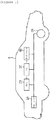
- FIG. 1 is a diagram schematically illustrating an electric vehicle to which a battery SOC estimating apparatus according to an exemplary embodiment of the present invention is applied.
- FIG. 1 illustrates an example in which a battery SOC estimating apparatus according to an exemplary embodiment of the present invention is applied to an electric vehicle.
- the battery SOC estimating apparatus according to an exemplary embodiment of the present invention may be applied to any technical fields such as a domestic or industrial energy storage system (ESS) or an uninterruptible power supply (UPS) system, if a secondary cell is applied thereto, other than the electric vehicle.
- ESS domestic or industrial energy storage system
- UPS uninterruptible power supply
- the electric vehicle 1 may include a battery 10, a battery management system (BMS) 20, an electronic control unit (ECU) 30, an inverter 40, and a motor 50.
- BMS battery management system
- ECU electronice control unit
- inverter 40 inverter 40
- motor 50 a motor 50.
- the battery 10 is an electric energy source which supplies a driving force to the motor 50 to drive the electric vehicle 1.
- the battery 10 may be charged or discharged by the inverter 40 in accordance with the driving of the motor 50 and/or an internal combustion engine (not illustrated).
- a type of the battery 10 is not specifically limited, and for example, the battery 10 may be configured by a lithium ion battery, a lithium polymer battery, a nickel cadmium battery, a nickel hydrogen battery, or a nickel zinc battery.
- the battery 10 is formed of a battery pack in which a plurality of battery cells are connected in series and/or parallel. One or more battery packs are provided to form the battery 10.
- the BMS 20 estimates a state of the battery 10 and manages the battery 10 using estimated state information. For example, the BMS 20 estimates and manages state information of the battery 10 such as a state of charging (SOC), a state of health (SOH), a maximum input/output power capability, or an output voltage of the battery. The BMS 20 controls charging or discharging of the battery 10 using the state information and further may also estimate a time to replace the battery 10.
- SOC state of charging
- SOH state of health
- the BMS 20 controls charging or discharging of the battery 10 using the state information and further may also estimate a time to replace the battery 10.
- the BMS 20 may include a battery SOC estimating apparatus (100 of FIG. 2 ) which will be described below. Accuracy and reliability of estimating the SOC of the battery 10 may be improved using the battery SOC estimating apparatus.
- the ECU 30 is an electronic control device which controls a status of the electric vehicle 1. For example, the ECU 30 determines a degree of torque based on information such as an accelerator, a break, or a speed and controls an output of the motor 50 so as to comply with torque information.
- the ECU 30 sends a control signal to the inverter 40 so that the battery 10 is charged or discharged based on the state information such as SOC or SOH of the battery 10 which is transmitted from the BMS 20.
- the inverter 40 charges and discharges the battery 10 based on the control signal of the ECU 30.
- the motor 50 drives the electric vehicle 1 using an electric energy of the battery 10, based on the control information (for example, torque information) which is transmitted from the ECU 30.
- control information for example, torque information
- the electric vehicle 1 is driven using the electric energy of the battery 10 so that it is important to accurately estimate the state (for example, the SOC) of the battery 10.
- battery SOC estimating apparatus and method according to an exemplary embodiment of the present invention will be described below with reference to FIGS. 2 to 6 .
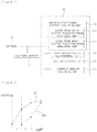
- FIG. 2 is a diagram schematically illustrating a battery SOC estimating apparatus according to an exemplary embodiment of the present invention.
- a battery SOC estimating apparatus 100 is connected to a battery 10 to estimate an SOC of the battery 10.
- the battery SOC estimating apparatus 100 may be included in at least one of a battery management system (BMS), a power monitoring system (for example, a remote supervisory control and data acquisition (SCADA) system), a user terminal, and a charger/discharger, which are connected to the battery 10, or may be embodied as a BMS, a power monitoring system, a user terminal, and a charger/discharger.
- BMS battery management system
- SCADA remote supervisory control and data acquisition
- the battery SOC estimating apparatus 100 may include an input/output power pattern analyzing unit 110, an application status determining unit 120, an SOC calculating unit 130, and a current sensor checking unit 140.
- the battery SOC estimating apparatus 100 illustrated in FIG. 2 is an exemplary embodiment but constituent elements thereof are not limited to the exemplary embodiment illustrated in FIG. 2 and some constituent elements may be added, modified, or deleted if necessary.
- the input/output power pattern analyzing unit 110 analyzes an input/output power of the battery 10 for a predetermined time to obtain an input/output power pattern of the battery 10.
- the input/output power pattern may be a pattern having a high depth of discharge (DOD) in which a process of being charged at a predetermined level or higher and discharged at a predetermined level or lower continuously occurs or a pattern having a low depth of discharge in which a process of being repeated alternately above and below a specific SOC occurs.
- DOD depth of discharge
- the above-mentioned input/output power pattern may include a short-term input/output power pattern and a long-term input/output power pattern.
- the input/output power pattern analyzing unit 110 may include a short-term input/output power pattern analyzing unit 111 and a long-term input/output power pattern analyzing unit 112.
- the short-term input/output power pattern analyzing unit 111 analyzes an input/output power of the battery 10 for a first setting time to obtain a short-term input/output power pattern of the battery 10 and the long-term input/output power pattern analyzing unit 112 analyzes an input/output power of the battery 10 for a second setting time which is longer than the first setting time to obtain a long-term input/output power pattern of the battery 10.
- the first setting time and the second setting time may be set in advance as a fixed value in the battery SOC estimating apparatus 100 according to the exemplary embodiment of the present invention or input by a user.
- the first setting time may be one minute and the second setting time may be 60 minutes.
- the application status determining unit 120 analyzes the input/output power pattern of the battery 10 to determine a current application status of the battery 10.
- the current application status of the battery 10 means a condition where the battery 10 is currently applied and may be one or more of a constant current (CC) status, a photovoltaic (PV) status, a frequency regulation (FR) status, and a peak shaving (PS) status.
- the CC status refers to a status where a constant current flows in the battery 10 and the battery 10 is charged or discharged with the constant current.
- the PV status refers to a status where a power is photovoltaically generated in the battery 10.
- the FR status refers to a status where the battery 10 is used to adjust a frequency in order to maintain the frequency when a load is changed.
- the PS status refers to a status where the battery 10 is used to supply an emergency power in order to shave a peak load during a peak time of the system.
- the application status determining unit 120 may determine the current application status of the battery 10 as a CC status or a PV status.
- the application status determining unit 120 may determine the current application status of the battery 10 as the FR status or the PS status.
- the SOC calculating unit 130 calculates the SOC of the battery 10 using an SOC estimation algorithm corresponding to the current application status of the battery 10.
- the SOC estimation algorithm may include an extended Kalman filter (EKF) SOC estimation algorithm or a smart SOC moving estimation (SSME) algorithm.
- EKF extended Kalman filter
- SSME smart SOC moving estimation
- the EKF SOC estimation algorithm is a method which makes the battery as an electrical model and compares a theoretical output value of the battery model with an actual output value to estimate the SOC through active correction.
- An input value of the EKF SOC estimation algorithm is a voltage, a current, and a temperature and an output value is an SOC.
- the EKF SOC estimation algorithm has been widely known by plural known materials in the related art so that a specific description of how the SOC estimation is performed in the EKF SOC estimation algorithm will be omitted.
- the EKF SOC estimation algorithm has advantages in that a maximum error of the SOC is low, for example, 3% in a room temperature and the SOC estimation may be stably performed significantly regardless of the power pattern but has disadvantages in that the algorithm is sensitive to a parameter of the battery model, inevitably requires a current sensor and is sensitive to a change of the state of health (SOH) of the battery.
- SOH state of health
- the SSME algorithm is a method which estimates a change of an open circuit voltage (OCV) based on a change between a previous value and a current value of a terminal measurement voltage without using a current value and estimates the SOC based on the estimated OCV.
- An input value of the EKF SOC estimation algorithm is a voltage and a temperature and an output value is an SOC.
- the SSME algorithm will be described with reference to FIGS. 3 to 5 .
- FIGS. 3 to 5 are diagrams illustrating an SSME algorithm which is used for a battery SOC estimating apparatus according to an exemplary embodiment of the present invention.
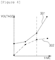
- FIGS. 3 and 4 are diagrams illustrating a method of estimating a change of an OCV in accordance with two voltage patterns.
- a curve of a measured voltage value 201 is converged as time goes by.
- an actual OCV is highly likely to be a converged voltage value so that the SSME algorithm makes an estimated OCV value 202 rapidly approach a measured voltage value 201.
- a curve of a measured voltage value 301 is diverged while the slope is increased as time goes by. This case may be highly likely to be a case when the voltage is bounced due to a high transient current so that the measured OCV value 301 may gradually follow the estimated OCV value 302 if possible.
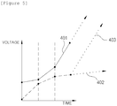
- FIG. 5 is a diagram illustrating a solving method of the SSME algorithm for a problem which may occur during the OCV estimation by two types of voltage patterns illustrated in FIGS. 3 and 4 .
- a correction factor in accordance with a moving average is used. That is, when a difference between the moving average value and the estimated OCV value is larger than a predetermined level, a curve 403 is created using the correction factor such that the estimated OCV value follows the measured voltage value 401 regardless of the voltage pattern.
- the SSME algorithm has advantages in that no current sensor is required and the errors are not accumulated but has disadvantages in that accuracy is low in a linear power pattern and the maximum error of the SOC is 5% at the room temperature which is a little bit higher than that of the EKF SOC estimation algorithm.
- the SOC estimation algorithms described above have distinct advantages and disadvantages so that it is difficult to conclude which one is better than the other. SOC accuracy of the SOC estimation algorithms may vary depending on the input/output power pattern of the battery 10. Therefore, the SOC calculating unit 130 calculates the SOC of the battery 10 using an appropriate SOC estimating algorithm corresponding to the current application status of the battery 10 to increase the accuracy of the SOC.
- the SOC calculating unit 130 may calculate the SOC of the battery 10 using the EKF SOC estimation algorithm.
- the current application status of the battery 10 is the CC status or the PV status
- a constant current flows in the battery 10 so that the linear power pattern may be shown. Therefore, if the EKF SOC estimation algorithm is used rather than the SSME algorithm, a more accurate SOC may be calculated.
- Most of the application status of the battery 10 may show a linear power pattern except for the FR status or the PS status so that the EKF SOC estimation algorithm may be applied in the most of the current application status of the battery 10.
- the SOC calculating unit 130 may calculate the SOC of the battery 10 using the SSME algorithm.
- the current application status of the battery 10 is the FR status or the PS status
- the SOC calculating unit 130 may calculate the SOC of the battery 10 using the EKF SOC estimation algorithm.
- DOD of the battery 10 is high, a process of being charged at a predetermined level or higher and discharged at a predetermined level or lower consistently occurs, which may show a linear power pattern. Accordingly, when the EKF SOC estimation algorithm is used instead of the SSME algorithm, a more accurate SOC may be calculated.
- the predetermined reference value may be set in advance in the SOC calculating unit 130 as a fixed value or input by a user.
- the SOC calculating unit 130 may calculate the SOC of the battery 10 using the SSME algorithm.
- the DOD of the battery 10 is low, the power pattern is repeated alternately above and below a specific SOC, which may show a non-linear power pattern. Accordingly, when the SSME algorithm is used instead of the EKF SOC estimation algorithm, a more accurate SOC may be calculated.
- the current sensor checking unit 140 checks whether a current sensor 11 which measures a value of a current which is input/output to/from the battery 10 is provided or the current sensor 11 normally operates.
- the SOC calculating unit 130 directly uses the SSME algorithm to calculate the SOC of the battery 10. This is because the SSME algorithm does not require the current value so that no current sensor 11 is required.
- FIG. 6 is a flowchart illustrating a battery SOC estimating method according to an exemplary embodiment of the present invention.
- the battery SOC estimating method when the battery SOC estimating method according to an exemplary embodiment of the present invention starts, first, it is checked whether a current sensor is provided in S10 and the current sensor normally operates in S20. If it is determined that no current sensor is provided or the current sensor abnormally operates, the SSME algorithm is immediately used in S80 to calculate an SOC in step S90.
- an input/output power of the battery during a predetermined time is analyzed to obtain an input/output power pattern of the battery.
- the input/output power pattern includes a short-term input/output power pattern and a long-term input/output power pattern.
- a process of obtaining the input/output power pattern of the battery may include a step of analyzing the input/output power of the battery for a first setting time to obtain the short-term input/output power pattern of the battery (S30) and a step of analyzing the input/output power of the battery for a second setting time which is longer than the first setting time to obtain the long-term input/output power pattern of the battery (S40).
- the input/output power pattern of the battery is analyzed to determine a current application status of the battery in S50.
- an SOC estimation algorithm corresponding to the current application status of the battery is used to calculate the SOC of the battery in steps S60, S70, S80, and S90.
- the EKF SOC estimation algorithm (S70) is used to calculate the SOC of the battery in step S90 and when the current application status (S60) of the battery is an FR status or a PS status, the SSME algorithm (S80) is used to calculate the SOC of the battery in step S90.
Landscapes
- Physics & Mathematics (AREA)
- General Physics & Mathematics (AREA)
- Secondary Cells (AREA)
- Charge And Discharge Circuits For Batteries Or The Like (AREA)
Description
- The present invention relates to an apparatus and a method for estimating a state of charging of a battery, and more particularly, to an apparatus and a method for estimating a state of charging of a battery which analyze an input/output power pattern of a battery for a predetermined time to determine a current application status of a battery and calculate a state of charging (SOC) of the battery using an SOC estimation algorithm corresponding to the current application status of the battery so that an estimation algorithm which is suitable for a situation when estimating the SOC of the battery is actively applied to minimize an SOC estimating error of the battery to obtain a more accurate SOC estimating value of the battery.
- A secondary battery which has a high applicability to a product group and an electrical property such as a high energy density is widely applied not only to portable equipment, but also an electric vehicle (EV) or a hybrid vehicle (HV) which is driven by an electrical driving source or an energy storage system (ESS) or an uninterruptible power supply (UPS) system which uses a medium or large size battery used for domestic or industrial purpose.
- Such a secondary battery has a primary advantage which drastically reduces the usage of a fossil fuel but does not create by-products in accordance with the usage of the energy, so that the secondary battery has drawn attention as a new energy source which is environmentally friendly and improves energy efficiency.
- When the secondary battery is embodied as a battery for a portable terminal, the utilization of the secondary battery to a high capacity environment is not necessarily increased. However, the battery which is applied to the electric vehicle or an energy storage source is generally used such that a plurality of unit secondary battery cells is grouped together to increase utilization for a high capacity environment.
- When such a battery, specifically, a plurality of secondary batteries alternately charged and discharged, it is required to manage the battery such that the charging and the discharging of the batteries are efficiently controlled to maintain appropriate operation status and performance.
- To this end, a battery management system (BMS) which manages the status and the performance of the battery is provided. The BMS measures a current, a voltage, or a temperature of the battery to estimate a state of charging (SOC) of the battery based on the measured current, voltage, and temperature and controls the SOC so that the fuel consumption efficiency is the best. In order to correctly control the SOC, it is required to correctly measure the SOC of the battery which is being charged and discharged.
- A method which measures an SOC of the battery in the BMS of the related art includes a method which accumulates a charged/discharged current which flows in the battery to estimate an SOC of the battery. However, according to this method, an error which is generated when a current is measured by a current sensor is continuously accumulated so that an accuracy of the SOC is lowered as time goes by.
- Alternatively, there is a method which measures a voltage of a battery while charging/discharging the battery, estimates an open loop voltage (OCV) of the battery in a non-loaded status from the measured voltage and maps the SOC corresponding to the estimated open loop voltage referring to an SOC table for every open loop voltage. However, the voltage which is measured while charging or discharging the battery is largely different from an actual voltage. For example, when the battery is connected to a load to start discharging the battery, the voltage of the battery is suddenly lowered and when the charging of the battery is started from an external power source, the voltage of the battery is suddenly increased. Accordingly, an accuracy of the SOC may be lowered due to an error between the voltage measured at the time of charging/discharging the battery and the actual voltage.
-
EP2233938 discloses a method for measuring SOC of a battery in a battery management system and an apparatus therefor, and more particularly, a method for setting up SOCi (State Of Charge based on current) or SOCv(State Of Charge based on voltage) to SOC of a battery in a battery management system according to a desired condition using a simple equivalent circuit, and an apparatus therefor. -
WO2010140230 discloses an apparatus for calculating the charging rate (CR) of a battery and a method therefor. The disclosed apparatus includes a first CR calculating unit to output a first CR calculated based on voltage data, a second CR calculating unit to output a second CR calculated based on current data, a rate of change (ROC) calculating unit to calculate a ROC of the voltage data, a ROC static state determination section to output a determination result determining that the ROC is settled below a predetermined threshold value during a predetermined period of time or more. It also comprises a CR decision unit to output, based on the determination result, the first CR as an effective CR if the ROC has been settled, and the second CR as the effective CR if the ROC has not been settled. - The present invention has been made in an effort to provide an apparatus and a method for estimating a state of charging of a battery which analyze an input/output power pattern of a battery for a predetermined time to determine a current application (Please add page 3a) status of a battery and calculate an SOC of the battery using an SOC estimation algorithm corresponding to the current application status of the battery so that when the SOC of the battery is estimated, an estimation algorithm which is suitable for a situation is actively applied to minimize an SOC estimating error of the battery to obtain a more exact SOC estimating value of the battery.
- An exemplary embodiment of the present invention is according to the appended
claim 1. - The input/output power pattern may include a short-term input/output power pattern and a long-term input/output power pattern. In this case, the input/output power pattern analyzing unit may include a short-term input/output power pattern analyzing unit which analyzes an input/output power of a battery during a first setting time to obtain a short-term input/output power pattern of the battery; and a long-term input/output power pattern analyzing unit which analyzes an input/output power of the battery during a second setting time which is longer than the first setting time to obtain a long-term input/output power pattern of the battery.
- When a depth of discharge (DOD) of the input/output power pattern of the battery is a predetermined reference value or higher, the SOC calculating unit may calculate the SOC of the battery using the EKF SOC estimation algorithm.
- When the DOD of the input/output power pattern of the battery is lower than a predetermined reference value, the SOC calculating unit may calculate the SOC of the battery using the SSME algorithm.
- The battery SOC estimating apparatus may further include a current sensor checking unit which checks whether a current sensor which measures a value of a current which is input/output to/from the battery is provided or the current sensor normally operates.
- If the current sensor checking unit determines that no current sensor is provided or the current sensor abnormally operates, the SOC calculating unit may calculate the SOC of the battery using the SSME algorithm.
- Another exemplary embodiment of the present invention provides a battery SOC estimating method according to appended claim 7.
- The input/output power pattern may include a short-term input/output power pattern and a long-term input/output power pattern. In this case, the obtaining of an input/output power pattern of a battery may include obtaining a short-term input/output power pattern of the battery by analyzing an input/output power of a battery during a first setting time; and obtaining a long-term input/output power pattern of the battery by analyzing an input/output power of the battery during a second setting time which is longer than the first setting time.
- When a depth of discharge (DOD) of the input/output power pattern of the battery is a predetermined reference value or higher, the calculating of an SOC of the battery may include calculating the SOC of the battery using the EKF SOC estimation algorithm.
- When the DOD of the input/output power pattern of the battery is lower than a predetermined reference value, the calculating of an SOC of the battery may include calculating the SOC of the battery using the SSME algorithm.
- The battery SOC estimating method may further include checking whether a current sensor which measures a value of a current which is input/output to/from the battery is provided or the current sensor normally operates.
- If it is determined that no current sensor is provided or the current sensor abnormally operates in the checking whether a current sensor is provided, the calculating of an SOC of the battery may include calculating the SOC of the battery using the SSME algorithm.
- According to an aspect of the present invention, it is possible to provide an apparatus and a method for estimating a state of charging of a battery which analyze an input/output power pattern of a battery for a predetermined time to determine a current application status of a battery and calculate an SOC of the battery using an SOC estimation algorithm corresponding to the current application status of the battery so that an estimation algorithm which is suitable for a situation when estimating the SOC of the battery is actively applied to minimize an SOC estimating error of the battery to obtain a more exact SOC estimating value of the battery.
-
-
FIG. 1 is a diagram schematically illustrating an electric vehicle to which a battery SOC estimating apparatus according to an exemplary embodiment of the present invention is applied. -
FIG. 2 is a diagram schematically illustrating a battery SOC estimating apparatus according to an exemplary embodiment of the present invention. -
FIGS. 3 to 5 are diagrams illustrating an SSME algorithm which is used for a battery SOC estimating apparatus according to an exemplary embodiment of the present invention. -
FIG. 6 is a flowchart illustrating a battery SOC estimating method according to an exemplary embodiment of the present invention. - The present invention will be described in detail below with reference to the accompanying drawings. Herein, repeated description and the detailed description of a known function and configuration that may make the purpose of the present invention unnecessarily ambiguous will be omitted. Exemplary embodiments of the present invention are provided so that those skilled in the art may more completely understand the present invention. Accordingly, the shape, the size, etc., of elements in the figures may be exaggerated for explicit comprehension.
- In the specification, unless explicitly described to the contrary, the word "comprise" and variations such as "comprises" or "comprising", will be understood to imply the inclusion of stated elements but not the exclusion of any other elements.
- The term "-unit" described in the specification means a unit for processing at least one function and operation and can be implemented by hardware components or software components or combinations thereof.
- An electric vehicle which will be described below refers to a vehicle which includes one or more electric motors in order to obtain momentum. An energy which is used to drive the electric vehicle includes an electric source such as a rechargeable battery and/or a fuel cell. The electric vehicle may be a hybrid electric vehicle which uses an internal combustion engine as another power source.
-
FIG. 1 is a diagram schematically illustrating an electric vehicle to which a battery SOC estimating apparatus according to an exemplary embodiment of the present invention is applied. -
FIG. 1 illustrates an example in which a battery SOC estimating apparatus according to an exemplary embodiment of the present invention is applied to an electric vehicle. However, the battery SOC estimating apparatus according to an exemplary embodiment of the present invention may be applied to any technical fields such as a domestic or industrial energy storage system (ESS) or an uninterruptible power supply (UPS) system, if a secondary cell is applied thereto, other than the electric vehicle. - The
electric vehicle 1 may include abattery 10, a battery management system (BMS) 20, an electronic control unit (ECU) 30, aninverter 40, and amotor 50. - The
battery 10 is an electric energy source which supplies a driving force to themotor 50 to drive theelectric vehicle 1. Thebattery 10 may be charged or discharged by theinverter 40 in accordance with the driving of themotor 50 and/or an internal combustion engine (not illustrated). - Here, a type of the
battery 10 is not specifically limited, and for example, thebattery 10 may be configured by a lithium ion battery, a lithium polymer battery, a nickel cadmium battery, a nickel hydrogen battery, or a nickel zinc battery. - The
battery 10 is formed of a battery pack in which a plurality of battery cells are connected in series and/or parallel. One or more battery packs are provided to form thebattery 10. - The BMS 20 estimates a state of the
battery 10 and manages thebattery 10 using estimated state information. For example, theBMS 20 estimates and manages state information of thebattery 10 such as a state of charging (SOC), a state of health (SOH), a maximum input/output power capability, or an output voltage of the battery. TheBMS 20 controls charging or discharging of thebattery 10 using the state information and further may also estimate a time to replace thebattery 10. - The
BMS 20 according to the present invention may include a battery SOC estimating apparatus (100 ofFIG. 2 ) which will be described below. Accuracy and reliability of estimating the SOC of thebattery 10 may be improved using the battery SOC estimating apparatus. - The
ECU 30 is an electronic control device which controls a status of theelectric vehicle 1. For example, theECU 30 determines a degree of torque based on information such as an accelerator, a break, or a speed and controls an output of themotor 50 so as to comply with torque information. - The
ECU 30 sends a control signal to theinverter 40 so that thebattery 10 is charged or discharged based on the state information such as SOC or SOH of thebattery 10 which is transmitted from theBMS 20. - The
inverter 40 charges and discharges thebattery 10 based on the control signal of theECU 30. - The
motor 50 drives theelectric vehicle 1 using an electric energy of thebattery 10, based on the control information (for example, torque information) which is transmitted from theECU 30. - The
electric vehicle 1 is driven using the electric energy of thebattery 10 so that it is important to accurately estimate the state (for example, the SOC) of thebattery 10. - Accordingly, battery SOC estimating apparatus and method according to an exemplary embodiment of the present invention will be described below with reference to
FIGS. 2 to 6 . -
FIG. 2 is a diagram schematically illustrating a battery SOC estimating apparatus according to an exemplary embodiment of the present invention. - Referring to
FIG. 2 , a batterySOC estimating apparatus 100 according to an exemplary embodiment of the present invention is connected to abattery 10 to estimate an SOC of thebattery 10. The batterySOC estimating apparatus 100 according to the exemplary embodiment of the present invention may be included in at least one of a battery management system (BMS), a power monitoring system (for example, a remote supervisory control and data acquisition (SCADA) system), a user terminal, and a charger/discharger, which are connected to thebattery 10, or may be embodied as a BMS, a power monitoring system, a user terminal, and a charger/discharger. - The battery
SOC estimating apparatus 100 according to the exemplary embodiment of the present invention may include an input/output powerpattern analyzing unit 110, an applicationstatus determining unit 120, anSOC calculating unit 130, and a currentsensor checking unit 140. The batterySOC estimating apparatus 100 illustrated inFIG. 2 is an exemplary embodiment but constituent elements thereof are not limited to the exemplary embodiment illustrated inFIG. 2 and some constituent elements may be added, modified, or deleted if necessary. - The input/output power
pattern analyzing unit 110 analyzes an input/output power of thebattery 10 for a predetermined time to obtain an input/output power pattern of thebattery 10. The input/output power pattern may be a pattern having a high depth of discharge (DOD) in which a process of being charged at a predetermined level or higher and discharged at a predetermined level or lower continuously occurs or a pattern having a low depth of discharge in which a process of being repeated alternately above and below a specific SOC occurs. - The above-mentioned input/output power pattern may include a short-term input/output power pattern and a long-term input/output power pattern. The input/output power
pattern analyzing unit 110 may include a short-term input/output power pattern analyzing unit 111 and a long-term input/output powerpattern analyzing unit 112. - The short-term input/output power pattern analyzing unit 111 analyzes an input/output power of the
battery 10 for a first setting time to obtain a short-term input/output power pattern of thebattery 10 and the long-term input/output powerpattern analyzing unit 112 analyzes an input/output power of thebattery 10 for a second setting time which is longer than the first setting time to obtain a long-term input/output power pattern of thebattery 10. In this case, the first setting time and the second setting time may be set in advance as a fixed value in the batterySOC estimating apparatus 100 according to the exemplary embodiment of the present invention or input by a user. For example, the first setting time may be one minute and the second setting time may be 60 minutes. - The application
status determining unit 120 analyzes the input/output power pattern of thebattery 10 to determine a current application status of thebattery 10. The current application status of thebattery 10 means a condition where thebattery 10 is currently applied and may be one or more of a constant current (CC) status, a photovoltaic (PV) status, a frequency regulation (FR) status, and a peak shaving (PS) status. The CC status refers to a status where a constant current flows in thebattery 10 and thebattery 10 is charged or discharged with the constant current. The PV status refers to a status where a power is photovoltaically generated in thebattery 10. The FR status refers to a status where thebattery 10 is used to adjust a frequency in order to maintain the frequency when a load is changed. The PS status refers to a status where thebattery 10 is used to supply an emergency power in order to shave a peak load during a peak time of the system. - Generally, in the CC status or the PV status, a process of being charged at a predetermined level or higher and discharged at a predetermined level or lower consistently occurs so that the input/output power pattern of the
battery 10 has a high DOD. Therefore, in the case of the above pattern, the applicationstatus determining unit 120 may determine the current application status of thebattery 10 as a CC status or a PV status. - In the FR status or the PS status, a process of being repeated alternately above and below a specific SOC occurs so that the input/output power pattern of the
battery 10 has a low depth of discharge. Therefore, in the case of this pattern, the applicationstatus determining unit 120 may determine the current application status of thebattery 10 as the FR status or the PS status. - The
SOC calculating unit 130 calculates the SOC of thebattery 10 using an SOC estimation algorithm corresponding to the current application status of thebattery 10. The SOC estimation algorithm may include an extended Kalman filter (EKF) SOC estimation algorithm or a smart SOC moving estimation (SSME) algorithm. - The EKF SOC estimation algorithm is a method which makes the battery as an electrical model and compares a theoretical output value of the battery model with an actual output value to estimate the SOC through active correction. An input value of the EKF SOC estimation algorithm is a voltage, a current, and a temperature and an output value is an SOC. The EKF SOC estimation algorithm has been widely known by plural known materials in the related art so that a specific description of how the SOC estimation is performed in the EKF SOC estimation algorithm will be omitted.
- The EKF SOC estimation algorithm has advantages in that a maximum error of the SOC is low, for example, 3% in a room temperature and the SOC estimation may be stably performed significantly regardless of the power pattern but has disadvantages in that the algorithm is sensitive to a parameter of the battery model, inevitably requires a current sensor and is sensitive to a change of the state of health (SOH) of the battery.
- The SSME algorithm is a method which estimates a change of an open circuit voltage (OCV) based on a change between a previous value and a current value of a terminal measurement voltage without using a current value and estimates the SOC based on the estimated OCV. An input value of the EKF SOC estimation algorithm is a voltage and a temperature and an output value is an SOC. Hereinafter, the SSME algorithm will be described with reference to
FIGS. 3 to 5 . -
FIGS. 3 to 5 are diagrams illustrating an SSME algorithm which is used for a battery SOC estimating apparatus according to an exemplary embodiment of the present invention. -
FIGS. 3 and4 are diagrams illustrating a method of estimating a change of an OCV in accordance with two voltage patterns. - Referring to
FIG. 3 , a curve of a measuredvoltage value 201 is converged as time goes by. In this case, an actual OCV is highly likely to be a converged voltage value so that the SSME algorithm makes an estimatedOCV value 202 rapidly approach a measuredvoltage value 201. - Referring to
FIG. 4 , a curve of a measuredvoltage value 301 is diverged while the slope is increased as time goes by. This case may be highly likely to be a case when the voltage is bounced due to a high transient current so that the measuredOCV value 301 may gradually follow the estimatedOCV value 302 if possible. -
FIG. 5 is a diagram illustrating a solving method of the SSME algorithm for a problem which may occur during the OCV estimation by two types of voltage patterns illustrated inFIGS. 3 and4 . - In the case of the voltage pattern in which a curve of the measured
voltage value 401 is diverged with an increased slope as time goes by, if the voltage is not temporarily diverged as described with reference toFIG. 4 but consistently diverged, the estimated OCV value cannot follow the measuredvoltage value 401 when it is required like thecurve 402 so that an error may be increased. Therefore, in the SSME algorithm, a correction factor in accordance with a moving average is used. That is, when a difference between the moving average value and the estimated OCV value is larger than a predetermined level, acurve 403 is created using the correction factor such that the estimated OCV value follows the measuredvoltage value 401 regardless of the voltage pattern. - The SSME algorithm has advantages in that no current sensor is required and the errors are not accumulated but has disadvantages in that accuracy is low in a linear power pattern and the maximum error of the SOC is 5% at the room temperature which is a little bit higher than that of the EKF SOC estimation algorithm.
- The SOC estimation algorithms described above have distinct advantages and disadvantages so that it is difficult to conclude which one is better than the other. SOC accuracy of the SOC estimation algorithms may vary depending on the input/output power pattern of the
battery 10. Therefore, theSOC calculating unit 130 calculates the SOC of thebattery 10 using an appropriate SOC estimating algorithm corresponding to the current application status of thebattery 10 to increase the accuracy of the SOC. - In one exemplary embodiment, when the current application status of the
battery 10 is the CC status or the PV status, theSOC calculating unit 130 may calculate the SOC of thebattery 10 using the EKF SOC estimation algorithm. When the current application status of thebattery 10 is the CC status or the PV status, a constant current flows in thebattery 10 so that the linear power pattern may be shown. Therefore, if the EKF SOC estimation algorithm is used rather than the SSME algorithm, a more accurate SOC may be calculated. Most of the application status of thebattery 10 may show a linear power pattern except for the FR status or the PS status so that the EKF SOC estimation algorithm may be applied in the most of the current application status of thebattery 10. - When the current application status of the
battery 10 is the FR status or the PS status, theSOC calculating unit 130 may calculate the SOC of thebattery 10 using the SSME algorithm. When the current application status of thebattery 10 is the FR status or the PS status, a current repeatedly flows in thebattery 10 to be alternately high and low so that a non-linear power pattern may be shown. Therefore, if the SSME algorithm is used rather than the EKF SOC estimation algorithm, a more accurate SOC may be calculated. - In another exemplary embodiment, when a depth of discharge (DOD) of the input/output power pattern of the
battery 10 is a predetermined reference value or higher, theSOC calculating unit 130 may calculate the SOC of thebattery 10 using the EKF SOC estimation algorithm. When the DOD of thebattery 10 is high, a process of being charged at a predetermined level or higher and discharged at a predetermined level or lower consistently occurs, which may show a linear power pattern. Accordingly, when the EKF SOC estimation algorithm is used instead of the SSME algorithm, a more accurate SOC may be calculated. The predetermined reference value may be set in advance in theSOC calculating unit 130 as a fixed value or input by a user. - When the DOD of the input/output power pattern of the
battery 10 is below the predetermined reference value, theSOC calculating unit 130 may calculate the SOC of thebattery 10 using the SSME algorithm. When the DOD of thebattery 10 is low, the power pattern is repeated alternately above and below a specific SOC, which may show a non-linear power pattern. Accordingly, when the SSME algorithm is used instead of the EKF SOC estimation algorithm, a more accurate SOC may be calculated. - The current
sensor checking unit 140 checks whether acurrent sensor 11 which measures a value of a current which is input/output to/from thebattery 10 is provided or thecurrent sensor 11 normally operates. - As a checking result in the current
sensor checking unit 140, if it is determined that nocurrent sensor 11 is provided or thecurrent sensor 11 abnormally operates, theSOC calculating unit 130 directly uses the SSME algorithm to calculate the SOC of thebattery 10. This is because the SSME algorithm does not require the current value so that nocurrent sensor 11 is required. -
FIG. 6 is a flowchart illustrating a battery SOC estimating method according to an exemplary embodiment of the present invention. - Referring to
FIG. 6 , when the battery SOC estimating method according to an exemplary embodiment of the present invention starts, first, it is checked whether a current sensor is provided in S10 and the current sensor normally operates in S20. If it is determined that no current sensor is provided or the current sensor abnormally operates, the SSME algorithm is immediately used in S80 to calculate an SOC in step S90. - If it is determined that the current sensor is provided and normally operates, an input/output power of the battery during a predetermined time is analyzed to obtain an input/output power pattern of the battery. The input/output power pattern includes a short-term input/output power pattern and a long-term input/output power pattern. A process of obtaining the input/output power pattern of the battery may include a step of analyzing the input/output power of the battery for a first setting time to obtain the short-term input/output power pattern of the battery (S30) and a step of analyzing the input/output power of the battery for a second setting time which is longer than the first setting time to obtain the long-term input/output power pattern of the battery (S40).
- Next, the input/output power pattern of the battery is analyzed to determine a current application status of the battery in S50.
- Next, an SOC estimation algorithm corresponding to the current application status of the battery is used to calculate the SOC of the battery in steps S60, S70, S80, and S90.
- For example, when the current application status (S60) of the battery is a CC status or a PV status, the EKF SOC estimation algorithm (S70) is used to calculate the SOC of the battery in step S90 and when the current application status (S60) of the battery is an FR status or a PS status, the SSME algorithm (S80) is used to calculate the SOC of the battery in step S90.
- The above-described battery SOC estimating method has been described with reference to the flowchart illustrated in the drawing. In order to simply describe the present invention, the method has been described with reference to a series of block diagrams but the present invention is not limited to the order of the blocks and processes of some blocks may be performed in a different order from the order of the blocks illustrated and described in the specification or simultaneously performed with other blocks. Various different divergences, flow paths, and orders of the blocks which may achieve the same or similar result may be implemented. All blocks which have been illustrated may not be required to implement the method described in the specification.
- While a specific embodiment of the present invention has been illustrated and described, it is obvious to those skilled in the art that the technical scope of the present invention is not limited to the accompanying drawings and the above description and various modifications may be made without departing from the scope of the present invention which is defined by the accompanying claims.
Claims (12)
- A battery state of charging, SOC, estimating apparatus (100), comprising:an input/output power pattern analyzing unit (110) which analyzes an input/output power of a battery during a predetermined time to obtain an input/output power pattern of the battery;an application status determining unit (120) which analyzes the input/output power pattern of the battery to determine a current application status of the battery; andan SOC calculating unit (130) which calculates an SOC of the battery using a state of charging estimation algorithm corresponding to the current application status of the battery,characterized in that the current application status of the battery includes one or more of a constant current status, a photovoltaic status, a frequency regulation status, and a peak shaving status:- the constant current status referring to a status where a constant current flows in the battery and the battery is charged or discharged with the constant current;- the photovoltaic status referring to a status where a power is photovoltaically generated in the battery;- the frequency regulation status referring to a status where the battery is used to adjust a frequency in order to maintain the frequency when a load is changed; and- the peak shaving status refers to a status where the battery is used to supply an emergency power in order to shave a peak load during a peak time of the system;wherein a smart SOC moving estimation algorithm comprises estimating a change of an open circuit voltage based on change between a previous value and a current value of a terminal measurement voltage without using a current value, and estimating the SOC based on the estimated open circuit voltage;
the SOC estimation algorithm including an extended Kalman filter SOC estimation algorithm and the smart SOC moving estimation algorithm,
in that when the current application status of the battery is the constant current status or
the photovoltaic status, the SOC calculating unit calculates the SOC of the battery using the extended Kalman filter SOC estimation algorithm, and
in that when the current application status of the battery is the frequency regulation status or the peak shaving status, the SOC calculating unit calculates the SOC of the battery using the smart SOC moving estimation algorithm. - The apparatus (100) of claim 1, wherein the input/output power pattern includes a short-term input/output power pattern and a long-term input/output power pattern, and
the input/output power pattern analyzing unit (110) includes a short-term input/output power pattern analyzing unit (111) which analyzes an input/output power of a battery during a first setting time to obtain a short-term input/output power pattern of the battery; and
a long-term input/output power pattern analyzing unit (112) which analyzes an input/output power of the battery during a second setting time which is longer than the first setting time to obtain a long-term input/output power pattern of the battery. - The apparatus (100) of claim 1, wherein when a depth of discharge of the input/output power pattern of the battery is a predetermined reference value or higher, the SOC calculating unit (130) calculates the SOC of the battery using the extended Kalman filter SOC estimation algorithm.
- The apparatus (100) of claim 1, wherein when the DOD of the input/output power pattern of the battery is lower than a predetermined reference value, the SOC calculating unit (130) calculates the SOC of the battery using the smart SOC moving estimation algorithm.
- The apparatus (100) of claim 1, further comprising:
a current sensor checking unit (140) which checks whether a current sensor which measures a value of a current which is input/output to/from the battery is provided or the current sensor normally operates. - The apparatus (100) of claim 5, wherein if the current sensor checking unit (140) determines that no current sensor is provided or the current sensor abnormally operates, the SOC calculating unit (130) calculates the SOC of the battery using the smart SOC moving estimation algorithm.
- A battery state of charging estimating method, comprising:obtaining (S30, S40) an input/output power pattern of a battery by analyzing an input/output power of the battery during a predetermined time;determining (S50) a current application status of the battery by analyzing the input/output power pattern of the battery; andcalculating (S90) a state of charging of the battery using an SOC estimation algorithm corresponding to the current application status of the battery,characterized in that the current application status of the battery includes one or more of a constant current status, a photovoltaic status, a frequency regulation status, and a peak shaving status:- the constant current status referring to a status where a constant current flows in the battery and the battery is charged or discharged with the constant current;- the photovoltaic status referring to a status where a power is photovoltaically generated in the battery;- the frequency regulation status referring to a status where the battery is used to adjust a frequency in order to maintain the frequency when a load is changed; and- the peak shaving status refers to a status where the battery is used to supply an emergency power in order to shave a peak load during a peak time of the system;wherein a smart SOC moving estimation algorithm comprises estimating a change of an open circuit voltage based on change between a previous value and a current value of a terminal measurement voltage without using a current value, and estimating the SOC based on the estimated open circuit voltage;
the SOC estimation algorithm including an extended Kalman filter SOC estimation algorithm (S70) and the smart SOC moving estimation algorithm (S80),
in that when the current application status of the battery is the constant current status or the photovoltaic status, the SOC calculating unit calculates the SOC of the battery using the extended Kalman filter SOC estimation algorithm, and
in that when the current application status of the battery is the frequency regulation status or the peak shaving status, the SOC calculating unit calculates the SOC of the battery using the smart SOC moving estimation algorithm. - The method of claim 7, wherein the input/output power pattern includes a short-term input/output power pattern and a long-term input/output power pattern, and
the obtaining (S30, S40) of an input/output power pattern of a battery includes:obtaining (S30) a short-term input/output power pattern of the battery by analyzing an input/output power of a battery during a first setting time; andobtaining (S40) a long-term input/output power pattern of the battery by analyzing an input/output power of the battery during a second setting time which is longer than the first setting time. - The method of claim 7, wherein when a depth of discharge of the input/output power pattern of the battery is a predetermined reference value or higher, the calculating of an SOC of the battery includes calculating the SOC of the battery using (S70) the extended Kalman filter SOC estimation algorithm.
- The method of claim 7, wherein when the depth of discharge of the input/output power pattern of the battery is lower than a predetermined reference value, the calculating of an SOC of the battery includes calculating the SOC of the battery using (S80) the smart SOC moving estimation algorithm.
- The method of claim 7, further comprising:
checking whether a current sensor which measures a value of a current which is input/output to/from the battery is provided or the current sensor normally operates. - The method of claim 11, wherein if it is determined that no current sensor is provided or the current sensor abnormally operates in the checking whether a current sensor is provided, the calculating of a SOC of the battery includes calculating the SOC of the battery using the smart SOC moving estimation algorithm.
Applications Claiming Priority (2)
| Application Number | Priority Date | Filing Date | Title |
|---|---|---|---|
| KR1020120119709A KR101547005B1 (en) | 2012-10-26 | 2012-10-26 | Apparatus and method for estimating state of charging of battery |
| PCT/KR2013/009534 WO2014065614A1 (en) | 2012-10-26 | 2013-10-24 | Apparatus and method for estimating state of charge of battery |
Publications (3)
| Publication Number | Publication Date |
|---|---|
| EP2921870A1 EP2921870A1 (en) | 2015-09-23 |
| EP2921870A4 EP2921870A4 (en) | 2016-04-06 |
| EP2921870B1 true EP2921870B1 (en) | 2019-12-04 |
Family
ID=50544920
Family Applications (1)
| Application Number | Title | Priority Date | Filing Date |
|---|---|---|---|
| EP13838052.2A Active EP2921870B1 (en) | 2012-10-26 | 2013-10-24 | Apparatus and method for estimating state of charge of battery |
Country Status (7)
| Country | Link |
|---|---|
| US (1) | US9310441B2 (en) |
| EP (1) | EP2921870B1 (en) |
| JP (1) | JP5916024B2 (en) |
| KR (1) | KR101547005B1 (en) |
| CN (1) | CN104011554B (en) |
| TW (1) | TWI510799B (en) |
| WO (1) | WO2014065614A1 (en) |
Families Citing this family (27)
| Publication number | Priority date | Publication date | Assignee | Title |
|---|---|---|---|---|
| KR101547006B1 (en) * | 2012-10-26 | 2015-08-24 | 주식회사 엘지화학 | Apparatus and method for estimating state of charging of battery |
| KR101595956B1 (en) * | 2014-11-12 | 2016-02-22 | 충북대학교 산학협력단 | Apparatus and method for measuring state of charge(soc) for lithium ion battery |
| CN104360282B (en) * | 2014-11-19 | 2017-07-21 | 奇瑞新能源汽车技术有限公司 | A kind of variable length sliding window recognizes the battery charge state method of estimation of battery parameter |
| CN104859454B (en) * | 2014-12-19 | 2017-04-05 | 北汽福田汽车股份有限公司 | A kind of method of calibration and device of SOC calculated values |
| KR102530223B1 (en) * | 2015-03-03 | 2023-05-10 | 삼성전자주식회사 | Method and system for predicting remaining useful life(rul) of battery |
| KR101684092B1 (en) * | 2015-04-08 | 2016-12-07 | 현대자동차주식회사 | Apparatus and Method for caculating degradation degree |
| JP6495783B2 (en) * | 2015-08-25 | 2019-04-03 | 太陽誘電株式会社 | Control device, power storage device and moving body |
| KR101736717B1 (en) | 2015-12-28 | 2017-05-17 | 연세대학교 산학협력단 | Energy storage apparatus and method for controlling therof |
| WO2019074220A1 (en) | 2017-10-11 | 2019-04-18 | 주식회사 엘지화학 | Battery capacity estimation apparatus and method, and battery management apparatus provided with same and method thereof |
| KR102683336B1 (en) | 2017-10-11 | 2024-07-09 | 주식회사 엘지에너지솔루션 | Apparatus and method for estimating the capacity of a battery, apparatus and method for managing the battery having the same |
| US11026761B2 (en) | 2018-02-05 | 2021-06-08 | Covidien Lp | Methods of determining a relative state of charge of a battery for a surgical instrument and surgical instruments and computer-readable media implementing the same |
| KR102458526B1 (en) * | 2018-02-07 | 2022-10-25 | 주식회사 엘지에너지솔루션 | Apparatus and method for estimating soc base on operating state of battery |
| KR102375843B1 (en) | 2018-02-27 | 2022-03-17 | 주식회사 엘지에너지솔루션 | Apparatus and method for managing battery |
| CN110232219B (en) * | 2019-05-17 | 2022-12-16 | 华南理工大学 | A Data Mining-Based Approval Method for Dispatchable Capacity of Electric Vehicles |
| JP2020189516A (en) * | 2019-05-20 | 2020-11-26 | 本田技研工業株式会社 | Impact degree display device, impact degree display method, and program |
| US11275121B2 (en) | 2020-06-08 | 2022-03-15 | Semiconductor Components Industries, Llc | Methods and apparatus for computing parasitic resistance in a battery system |
| US11569668B2 (en) * | 2020-07-14 | 2023-01-31 | Igrenenergi, Inc. | System and method for dynamic balancing power in a battery pack |
| KR102759171B1 (en) * | 2020-08-13 | 2025-01-24 | 주식회사 엘지에너지솔루션 | Apparatus and method for predicting life of battery |
| KR102560584B1 (en) * | 2021-03-11 | 2023-08-02 | 경북대학교 산학협력단 | Cloud-based battery health analysis system and method |
| KR20220157530A (en) * | 2021-05-21 | 2022-11-29 | 현대자동차주식회사 | Apparatus and method for controlling battery capacity variable |
| KR102704458B1 (en) * | 2021-10-14 | 2024-09-06 | 인하대학교 산학협력단 | Method and Apparatus for Prediction of Battery Condition Based on Waveform Measurement |
| CN113655385B (en) * | 2021-10-19 | 2022-02-08 | 深圳市德兰明海科技有限公司 | Lithium battery SOC estimation method and device and computer readable storage medium |
| KR102851341B1 (en) * | 2022-07-29 | 2025-08-28 | 삼성전자주식회사 | Battery risk assessment device and method of operation thereof |
| CN116520232B (en) * | 2023-05-16 | 2026-03-17 | 湖南银杏电池智能管理技术有限公司 | A simulation verification method and system for battery SOC algorithm |
| KR20250034737A (en) | 2023-09-04 | 2025-03-11 | 엘지전자 주식회사 | Cleaner and Controlling method for the Cleaner |
| TWI901381B (en) * | 2023-10-10 | 2025-10-11 | 立錡科技股份有限公司 | Battery control parameter estimation system and battery control parameter estimation method |
| CN120792787B (en) * | 2025-09-05 | 2025-11-28 | 重庆长安汽车股份有限公司 | Methods, apparatuses, electronic devices and storage media for correcting state of charge |
Family Cites Families (34)
| Publication number | Priority date | Publication date | Assignee | Title |
|---|---|---|---|---|
| US3500167A (en) * | 1966-12-12 | 1970-03-10 | Vari Tech Co | Battery condition analyzer |
| US3617850A (en) * | 1968-12-09 | 1971-11-02 | North American Rockwell | Battery-status device |
| DK101692D0 (en) * | 1992-08-14 | 1992-08-14 | John Reipur | BATTERY CHARGING PROCEDURE AND APPARATUS |
| JP3583159B2 (en) | 1994-03-25 | 2004-10-27 | 株式会社日本自動車部品総合研究所 | Battery state determination device |
| US5606243A (en) | 1993-11-19 | 1997-02-25 | Nippon Soken, Inc. | Battery state judging apparatus |
| US5578915A (en) * | 1994-09-26 | 1996-11-26 | General Motors Corporation | Dynamic battery state-of-charge and capacity determination |
| JP3572381B2 (en) * | 1998-03-06 | 2004-09-29 | 日産自動車株式会社 | Calculation method of rechargeable battery charge capacity |
| JP3956932B2 (en) * | 2003-11-07 | 2007-08-08 | ソニー株式会社 | Charger and charging state determination method |
| US7525285B2 (en) * | 2004-11-11 | 2009-04-28 | Lg Chem, Ltd. | Method and system for cell equalization using state of charge |
| US7197487B2 (en) | 2005-03-16 | 2007-03-27 | Lg Chem, Ltd. | Apparatus and method for estimating battery state of charge |
| JP4587306B2 (en) | 2005-04-20 | 2010-11-24 | 株式会社デンソー | Secondary battery remaining capacity calculation method |
| JP4984527B2 (en) * | 2005-12-27 | 2012-07-25 | トヨタ自動車株式会社 | Secondary battery charge state estimation device and charge state estimation method |
| JP4680783B2 (en) * | 2006-01-16 | 2011-05-11 | プライムアースEvエナジー株式会社 | Secondary battery state detection device, state detection method, and state detection program |
| US7521895B2 (en) * | 2006-03-02 | 2009-04-21 | Lg Chem, Ltd. | System and method for determining both an estimated battery state vector and an estimated battery parameter vector |
| JP4820329B2 (en) * | 2007-05-09 | 2011-11-24 | 本田技研工業株式会社 | Storage amount calculation device and storage amount calculation method |
| KR100985667B1 (en) * | 2007-08-22 | 2010-10-05 | 주식회사 엘지화학 | Battery open circuit voltage estimator, battery charge state estimator and its control method |
| JP5217430B2 (en) * | 2007-12-28 | 2013-06-19 | トヨタ自動車株式会社 | Alternator control device and alternator control method |
| KR20090077657A (en) * | 2008-01-11 | 2009-07-15 | 에스케이에너지 주식회사 | Method and device for measuring SOC of battery in battery management system |
| KR100969567B1 (en) | 2008-07-04 | 2010-07-12 | 포항공과대학교 산학협력단 | Method and apparatus for detecting abnormal battery consumption of mobile communication terminal |
| WO2010090774A1 (en) * | 2009-02-07 | 2010-08-12 | Tau Science Corporation | High speed detection of shunt defects in photovoltaic and optoelectronic devices |
| JP5439126B2 (en) * | 2009-03-31 | 2014-03-12 | 株式会社日立製作所 | Status detector for power supply |
| WO2010140230A1 (en) * | 2009-06-03 | 2010-12-09 | 三菱重工業株式会社 | Battery state of charge calculation device |
| KR20110040220A (en) * | 2009-10-13 | 2011-04-20 | 엘지전자 주식회사 | Battery control device and method of the car |
| JP5407758B2 (en) * | 2009-10-29 | 2014-02-05 | トヨタ自動車株式会社 | Vehicle power supply |
| CN102062841B (en) * | 2009-11-11 | 2012-12-12 | 北汽福田汽车股份有限公司 | Estimation method and system of state of charge (SOC) of power battery |
| JP2011106952A (en) * | 2009-11-17 | 2011-06-02 | Honda Motor Co Ltd | Method for estimating residual capacity of battery |
| JP2011127973A (en) * | 2009-12-16 | 2011-06-30 | Kawasaki Heavy Ind Ltd | State of charge estimation method and device for secondary battery |
| EP2541266B1 (en) * | 2010-02-24 | 2014-07-16 | Mitsubishi Heavy Industries, Ltd. | Charging-rate computation system |
| JP5447282B2 (en) * | 2010-08-11 | 2014-03-19 | 新神戸電機株式会社 | Lead-acid battery and lead-acid battery system for natural energy utilization system |
| WO2012050014A1 (en) * | 2010-10-15 | 2012-04-19 | 三洋電機株式会社 | Power management system |
| JP2014504723A (en) | 2011-01-05 | 2014-02-24 | エルジー・ケム・リミテッド | Battery usable time estimation apparatus and method |
| JP5719236B2 (en) * | 2011-05-31 | 2015-05-13 | プライムアースEvエナジー株式会社 | Secondary battery control device |
| KR101547006B1 (en) * | 2012-10-26 | 2015-08-24 | 주식회사 엘지화학 | Apparatus and method for estimating state of charging of battery |
| CN104237791A (en) * | 2013-06-20 | 2014-12-24 | 电子科技大学 | Lithium battery charge state estimation method, battery management system and battery system |
-
2012
- 2012-10-26 KR KR1020120119709A patent/KR101547005B1/en active Active
-
2013
- 2013-10-24 WO PCT/KR2013/009534 patent/WO2014065614A1/en not_active Ceased
- 2013-10-24 JP JP2014543438A patent/JP5916024B2/en active Active
- 2013-10-24 US US14/359,768 patent/US9310441B2/en active Active
- 2013-10-24 CN CN201380004368.9A patent/CN104011554B/en active Active
- 2013-10-24 EP EP13838052.2A patent/EP2921870B1/en active Active
- 2013-10-25 TW TW102138689A patent/TWI510799B/en active
Non-Patent Citations (1)
| Title |
|---|
| None * |
Also Published As
| Publication number | Publication date |
|---|---|
| KR20140053590A (en) | 2014-05-08 |
| EP2921870A1 (en) | 2015-09-23 |
| KR101547005B1 (en) | 2015-08-24 |
| JP5916024B2 (en) | 2016-05-11 |
| TWI510799B (en) | 2015-12-01 |
| US9310441B2 (en) | 2016-04-12 |
| WO2014065614A1 (en) | 2014-05-01 |
| EP2921870A4 (en) | 2016-04-06 |
| CN104011554B (en) | 2016-06-22 |
| TW201439567A (en) | 2014-10-16 |
| JP2015505955A (en) | 2015-02-26 |
| US20150046107A1 (en) | 2015-02-12 |
| CN104011554A (en) | 2014-08-27 |
Similar Documents
| Publication | Publication Date | Title |
|---|---|---|
| US9310441B2 (en) | Apparatus and method for estimating stage of charge of battery | |
| EP2762907B1 (en) | Apparatus and method for estimating state of charge of battery | |
| EP2894486B1 (en) | Apparatus and method for estimating power of secondary battery comprising blended cathode material | |
| KR101572494B1 (en) | Apparatus of Estimating SOH for Battery | |
| US9166257B2 (en) | Method for charging and method for determining an end-of-charge criterion of a nickel-based battery | |
| US20190157896A1 (en) | Battery management apparatus and method for protecting a lithium iron phosphate cell from over-voltage using the same | |
| CN113193241B (en) | Battery system and lithium-ion battery degradation evaluation method | |
| KR101852664B1 (en) | Apparatus and method for measuring state of battery health | |
| EP4064510B1 (en) | Battery charging control method and device | |
| KR102564716B1 (en) | Battery management system and method for protecting a battery from over-discharge | |
| Manla et al. | Modeling of zinc bromide energy storage for vehicular applications | |
| CN105359329A (en) | Method for battery management and battery management system | |
| EP4571339B1 (en) | Battery management system, battery pack, electric vehicle, and battery management method | |
| KR20210098215A (en) | Apparatus and method for controlling charge and dsicharge of battery | |
| KR20130126231A (en) | Apparatus and method of estimating state of health for battery | |
| Ouyang et al. | Advanced Model-Based Charging Control for Lithium-Ion Batteries | |
| JP7113976B2 (en) | Charge/discharge control device and charge/discharge control method | |
| KR101741303B1 (en) | Voltage balancing apparatus and method between battery racks | |
| Bangaru et al. | Modeling and simulation of lithium-ion battery with hysteresis for industrial applications | |
| KR20230050028A (en) | Battery management system and method for battery monitoring thereof | |
| Singh et al. | Development of passive battery management system at TRL 4 | |
| Mon et al. | State-of-Charge Evaluation for Real-Time Monitoring and Evaluation of Lithium-Ion Battery Performance | |
| KR20250143489A (en) | Method and Apparatus for diagnosing battery | |
| Devi et al. | Analysis and Simulation of Charging/Discharging of Lithium-Ion Battery in Electric Vehicles | |
| Williard et al. | Predicting Remaining Capacity of Batteries for UAVs and Electric Vehicle Applications |
Legal Events
| Date | Code | Title | Description |
|---|---|---|---|
| PUAI | Public reference made under article 153(3) epc to a published international application that has entered the european phase |
Free format text: ORIGINAL CODE: 0009012 |
|
| 17P | Request for examination filed |
Effective date: 20150324 |
|
| AK | Designated contracting states |
Kind code of ref document: A1 Designated state(s): AL AT BE BG CH CY CZ DE DK EE ES FI FR GB GR HR HU IE IS IT LI LT LU LV MC MK MT NL NO PL PT RO RS SE SI SK SM TR |
|
| AX | Request for extension of the european patent |
Extension state: BA ME |
|
| DAX | Request for extension of the european patent (deleted) | ||
| RA4 | Supplementary search report drawn up and despatched (corrected) |
Effective date: 20160307 |
|
| RIC1 | Information provided on ipc code assigned before grant |
Ipc: G01R 31/36 20060101AFI20160301BHEP |
|
| GRAP | Despatch of communication of intention to grant a patent |
Free format text: ORIGINAL CODE: EPIDOSNIGR1 |
|
| STAA | Information on the status of an ep patent application or granted ep patent |
Free format text: STATUS: GRANT OF PATENT IS INTENDED |
|
| INTG | Intention to grant announced |
Effective date: 20190604 |
|
| GRAJ | Information related to disapproval of communication of intention to grant by the applicant or resumption of examination proceedings by the epo deleted |
Free format text: ORIGINAL CODE: EPIDOSDIGR1 |
|
| STAA | Information on the status of an ep patent application or granted ep patent |
Free format text: STATUS: REQUEST FOR EXAMINATION WAS MADE |
|
| INTC | Intention to grant announced (deleted) | ||
| GRAR | Information related to intention to grant a patent recorded |
Free format text: ORIGINAL CODE: EPIDOSNIGR71 |
|
| GRAS | Grant fee paid |
Free format text: ORIGINAL CODE: EPIDOSNIGR3 |
|
| STAA | Information on the status of an ep patent application or granted ep patent |
Free format text: STATUS: GRANT OF PATENT IS INTENDED |
|
| GRAA | (expected) grant |
Free format text: ORIGINAL CODE: 0009210 |
|
| STAA | Information on the status of an ep patent application or granted ep patent |
Free format text: STATUS: THE PATENT HAS BEEN GRANTED |
|
| INTG | Intention to grant announced |
Effective date: 20191024 |
|
| AK | Designated contracting states |
Kind code of ref document: B1 Designated state(s): AL AT BE BG CH CY CZ DE DK EE ES FI FR GB GR HR HU IE IS IT LI LT LU LV MC MK MT NL NO PL PT RO RS SE SI SK SM TR |
|
| REG | Reference to a national code |
Ref country code: GB Ref legal event code: FG4D |
|
| REG | Reference to a national code |
Ref country code: CH Ref legal event code: EP |
|
| REG | Reference to a national code |
Ref country code: AT Ref legal event code: REF Ref document number: 1210057 Country of ref document: AT Kind code of ref document: T Effective date: 20191215 |
|
| REG | Reference to a national code |
Ref country code: DE Ref legal event code: R096 Ref document number: 602013063696 Country of ref document: DE |
|
| REG | Reference to a national code |
Ref country code: IE Ref legal event code: FG4D |
|
| REG | Reference to a national code |
Ref country code: NL Ref legal event code: MP Effective date: 20191204 |
|
| REG | Reference to a national code |
Ref country code: LT Ref legal event code: MG4D |
|
| PG25 | Lapsed in a contracting state [announced via postgrant information from national office to epo] |
Ref country code: BG Free format text: LAPSE BECAUSE OF FAILURE TO SUBMIT A TRANSLATION OF THE DESCRIPTION OR TO PAY THE FEE WITHIN THE PRESCRIBED TIME-LIMIT Effective date: 20200304 Ref country code: FI Free format text: LAPSE BECAUSE OF FAILURE TO SUBMIT A TRANSLATION OF THE DESCRIPTION OR TO PAY THE FEE WITHIN THE PRESCRIBED TIME-LIMIT Effective date: 20191204 Ref country code: SE Free format text: LAPSE BECAUSE OF FAILURE TO SUBMIT A TRANSLATION OF THE DESCRIPTION OR TO PAY THE FEE WITHIN THE PRESCRIBED TIME-LIMIT Effective date: 20191204 Ref country code: LV Free format text: LAPSE BECAUSE OF FAILURE TO SUBMIT A TRANSLATION OF THE DESCRIPTION OR TO PAY THE FEE WITHIN THE PRESCRIBED TIME-LIMIT Effective date: 20191204 Ref country code: NO Free format text: LAPSE BECAUSE OF FAILURE TO SUBMIT A TRANSLATION OF THE DESCRIPTION OR TO PAY THE FEE WITHIN THE PRESCRIBED TIME-LIMIT Effective date: 20200304 Ref country code: LT Free format text: LAPSE BECAUSE OF FAILURE TO SUBMIT A TRANSLATION OF THE DESCRIPTION OR TO PAY THE FEE WITHIN THE PRESCRIBED TIME-LIMIT Effective date: 20191204 Ref country code: GR Free format text: LAPSE BECAUSE OF FAILURE TO SUBMIT A TRANSLATION OF THE DESCRIPTION OR TO PAY THE FEE WITHIN THE PRESCRIBED TIME-LIMIT Effective date: 20200305 |
|
| PG25 | Lapsed in a contracting state [announced via postgrant information from national office to epo] |
Ref country code: HR Free format text: LAPSE BECAUSE OF FAILURE TO SUBMIT A TRANSLATION OF THE DESCRIPTION OR TO PAY THE FEE WITHIN THE PRESCRIBED TIME-LIMIT Effective date: 20191204 Ref country code: RS Free format text: LAPSE BECAUSE OF FAILURE TO SUBMIT A TRANSLATION OF THE DESCRIPTION OR TO PAY THE FEE WITHIN THE PRESCRIBED TIME-LIMIT Effective date: 20191204 |
|
| PG25 | Lapsed in a contracting state [announced via postgrant information from national office to epo] |
Ref country code: AL Free format text: LAPSE BECAUSE OF FAILURE TO SUBMIT A TRANSLATION OF THE DESCRIPTION OR TO PAY THE FEE WITHIN THE PRESCRIBED TIME-LIMIT Effective date: 20191204 |
|
| PG25 | Lapsed in a contracting state [announced via postgrant information from national office to epo] |
Ref country code: CZ Free format text: LAPSE BECAUSE OF FAILURE TO SUBMIT A TRANSLATION OF THE DESCRIPTION OR TO PAY THE FEE WITHIN THE PRESCRIBED TIME-LIMIT Effective date: 20191204 Ref country code: RO Free format text: LAPSE BECAUSE OF FAILURE TO SUBMIT A TRANSLATION OF THE DESCRIPTION OR TO PAY THE FEE WITHIN THE PRESCRIBED TIME-LIMIT Effective date: 20191204 Ref country code: NL Free format text: LAPSE BECAUSE OF FAILURE TO SUBMIT A TRANSLATION OF THE DESCRIPTION OR TO PAY THE FEE WITHIN THE PRESCRIBED TIME-LIMIT Effective date: 20191204 Ref country code: EE Free format text: LAPSE BECAUSE OF FAILURE TO SUBMIT A TRANSLATION OF THE DESCRIPTION OR TO PAY THE FEE WITHIN THE PRESCRIBED TIME-LIMIT Effective date: 20191204 Ref country code: ES Free format text: LAPSE BECAUSE OF FAILURE TO SUBMIT A TRANSLATION OF THE DESCRIPTION OR TO PAY THE FEE WITHIN THE PRESCRIBED TIME-LIMIT Effective date: 20191204 Ref country code: PT Free format text: LAPSE BECAUSE OF FAILURE TO SUBMIT A TRANSLATION OF THE DESCRIPTION OR TO PAY THE FEE WITHIN THE PRESCRIBED TIME-LIMIT Effective date: 20200429 |
|
| PG25 | Lapsed in a contracting state [announced via postgrant information from national office to epo] |
Ref country code: SM Free format text: LAPSE BECAUSE OF FAILURE TO SUBMIT A TRANSLATION OF THE DESCRIPTION OR TO PAY THE FEE WITHIN THE PRESCRIBED TIME-LIMIT Effective date: 20191204 Ref country code: SK Free format text: LAPSE BECAUSE OF FAILURE TO SUBMIT A TRANSLATION OF THE DESCRIPTION OR TO PAY THE FEE WITHIN THE PRESCRIBED TIME-LIMIT Effective date: 20191204 Ref country code: IS Free format text: LAPSE BECAUSE OF FAILURE TO SUBMIT A TRANSLATION OF THE DESCRIPTION OR TO PAY THE FEE WITHIN THE PRESCRIBED TIME-LIMIT Effective date: 20200404 |
|
| REG | Reference to a national code |
Ref country code: DE Ref legal event code: R097 Ref document number: 602013063696 Country of ref document: DE |
|
| REG | Reference to a national code |
Ref country code: AT Ref legal event code: MK05 Ref document number: 1210057 Country of ref document: AT Kind code of ref document: T Effective date: 20191204 |
|
| PLBE | No opposition filed within time limit |
Free format text: ORIGINAL CODE: 0009261 |
|
| STAA | Information on the status of an ep patent application or granted ep patent |
Free format text: STATUS: NO OPPOSITION FILED WITHIN TIME LIMIT |
|
| PG25 | Lapsed in a contracting state [announced via postgrant information from national office to epo] |
Ref country code: DK Free format text: LAPSE BECAUSE OF FAILURE TO SUBMIT A TRANSLATION OF THE DESCRIPTION OR TO PAY THE FEE WITHIN THE PRESCRIBED TIME-LIMIT Effective date: 20191204 |
|
| 26N | No opposition filed |
Effective date: 20200907 |
|
| PG25 | Lapsed in a contracting state [announced via postgrant information from national office to epo] |
Ref country code: SI Free format text: LAPSE BECAUSE OF FAILURE TO SUBMIT A TRANSLATION OF THE DESCRIPTION OR TO PAY THE FEE WITHIN THE PRESCRIBED TIME-LIMIT Effective date: 20191204 Ref country code: PL Free format text: LAPSE BECAUSE OF FAILURE TO SUBMIT A TRANSLATION OF THE DESCRIPTION OR TO PAY THE FEE WITHIN THE PRESCRIBED TIME-LIMIT Effective date: 20191204 Ref country code: AT Free format text: LAPSE BECAUSE OF FAILURE TO SUBMIT A TRANSLATION OF THE DESCRIPTION OR TO PAY THE FEE WITHIN THE PRESCRIBED TIME-LIMIT Effective date: 20191204 |
|
| PG25 | Lapsed in a contracting state [announced via postgrant information from national office to epo] |
Ref country code: IT Free format text: LAPSE BECAUSE OF FAILURE TO SUBMIT A TRANSLATION OF THE DESCRIPTION OR TO PAY THE FEE WITHIN THE PRESCRIBED TIME-LIMIT Effective date: 20191204 |
|
| REG | Reference to a national code |
Ref country code: CH Ref legal event code: PL |
|
| PG25 | Lapsed in a contracting state [announced via postgrant information from national office to epo] |
Ref country code: MC Free format text: LAPSE BECAUSE OF FAILURE TO SUBMIT A TRANSLATION OF THE DESCRIPTION OR TO PAY THE FEE WITHIN THE PRESCRIBED TIME-LIMIT Effective date: 20191204 Ref country code: LU Free format text: LAPSE BECAUSE OF NON-PAYMENT OF DUE FEES Effective date: 20201024 |
|
| REG | Reference to a national code |
Ref country code: BE Ref legal event code: MM Effective date: 20201031 |
|
| PG25 | Lapsed in a contracting state [announced via postgrant information from national office to epo] |
Ref country code: BE Free format text: LAPSE BECAUSE OF NON-PAYMENT OF DUE FEES Effective date: 20201031 Ref country code: CH Free format text: LAPSE BECAUSE OF NON-PAYMENT OF DUE FEES Effective date: 20201031 Ref country code: LI Free format text: LAPSE BECAUSE OF NON-PAYMENT OF DUE FEES Effective date: 20201031 |
|
| PG25 | Lapsed in a contracting state [announced via postgrant information from national office to epo] |
Ref country code: IE Free format text: LAPSE BECAUSE OF NON-PAYMENT OF DUE FEES Effective date: 20201024 |
|
| PG25 | Lapsed in a contracting state [announced via postgrant information from national office to epo] |
Ref country code: TR Free format text: LAPSE BECAUSE OF FAILURE TO SUBMIT A TRANSLATION OF THE DESCRIPTION OR TO PAY THE FEE WITHIN THE PRESCRIBED TIME-LIMIT Effective date: 20191204 Ref country code: MT Free format text: LAPSE BECAUSE OF FAILURE TO SUBMIT A TRANSLATION OF THE DESCRIPTION OR TO PAY THE FEE WITHIN THE PRESCRIBED TIME-LIMIT Effective date: 20191204 Ref country code: CY Free format text: LAPSE BECAUSE OF FAILURE TO SUBMIT A TRANSLATION OF THE DESCRIPTION OR TO PAY THE FEE WITHIN THE PRESCRIBED TIME-LIMIT Effective date: 20191204 |
|
| PG25 | Lapsed in a contracting state [announced via postgrant information from national office to epo] |
Ref country code: MK Free format text: LAPSE BECAUSE OF FAILURE TO SUBMIT A TRANSLATION OF THE DESCRIPTION OR TO PAY THE FEE WITHIN THE PRESCRIBED TIME-LIMIT Effective date: 20191204 |
|
| P01 | Opt-out of the competence of the unified patent court (upc) registered |
Effective date: 20230512 |
|
| REG | Reference to a national code |
Ref country code: DE Ref legal event code: R081 Ref document number: 602013063696 Country of ref document: DE Owner name: LG ENERGY SOLUTION, LTD., KR Free format text: FORMER OWNER: LG CHEM, LTD., SEOUL, KR |
|
| REG | Reference to a national code |
Ref country code: GB Ref legal event code: 732E Free format text: REGISTERED BETWEEN 20230824 AND 20230831 |
|
| PGFP | Annual fee paid to national office [announced via postgrant information from national office to epo] |
Ref country code: GB Payment date: 20250922 Year of fee payment: 13 |
|
| PGFP | Annual fee paid to national office [announced via postgrant information from national office to epo] |
Ref country code: FR Payment date: 20250925 Year of fee payment: 13 |
|
| PGFP | Annual fee paid to national office [announced via postgrant information from national office to epo] |
Ref country code: DE Payment date: 20250922 Year of fee payment: 13 |