EP2921187B1 - Device and method for processing fluid - Google Patents
Device and method for processing fluid Download PDFInfo
- Publication number
- EP2921187B1 EP2921187B1 EP15163927.5A EP15163927A EP2921187B1 EP 2921187 B1 EP2921187 B1 EP 2921187B1 EP 15163927 A EP15163927 A EP 15163927A EP 2921187 B1 EP2921187 B1 EP 2921187B1
- Authority
- EP
- European Patent Office
- Prior art keywords
- inner bag
- bag
- fluid concentration
- fluid
- concentration device
- Prior art date
- Legal status (The legal status is an assumption and is not a legal conclusion. Google has not performed a legal analysis and makes no representation as to the accuracy of the status listed.)
- Active
Links
- 239000012530 fluid Substances 0.000 title claims description 99
- 238000000034 method Methods 0.000 title claims description 37
- 239000000463 material Substances 0.000 claims description 96
- 239000007788 liquid Substances 0.000 claims description 40
- 210000004369 blood Anatomy 0.000 claims description 39
- 239000008280 blood Substances 0.000 claims description 39
- 210000002381 plasma Anatomy 0.000 claims description 22
- 239000011236 particulate material Substances 0.000 claims description 19
- 239000011148 porous material Substances 0.000 claims description 16
- 229920000515 polycarbonate Polymers 0.000 claims description 7
- 239000004417 polycarbonate Substances 0.000 claims description 7
- 239000004800 polyvinyl chloride Substances 0.000 claims description 7
- 239000012528 membrane Substances 0.000 claims description 6
- 238000003466 welding Methods 0.000 claims description 5
- 229920000915 polyvinyl chloride Polymers 0.000 claims description 3
- 210000000601 blood cell Anatomy 0.000 description 23
- 239000012141 concentrate Substances 0.000 description 20
- 230000002745 absorbent Effects 0.000 description 11
- 239000002250 absorbent Substances 0.000 description 11
- 238000010923 batch production Methods 0.000 description 7
- 210000003743 erythrocyte Anatomy 0.000 description 5
- 210000000265 leukocyte Anatomy 0.000 description 5
- 239000002245 particle Substances 0.000 description 5
- 235000010443 alginic acid Nutrition 0.000 description 4
- 229920000615 alginic acid Polymers 0.000 description 4
- 238000010924 continuous production Methods 0.000 description 4
- 239000013618 particulate matter Substances 0.000 description 4
- -1 polyethylene Polymers 0.000 description 4
- HEMHJVSKTPXQMS-UHFFFAOYSA-M Sodium hydroxide Chemical compound [OH-].[Na+] HEMHJVSKTPXQMS-UHFFFAOYSA-M 0.000 description 3
- 238000004519 manufacturing process Methods 0.000 description 3
- 229920003023 plastic Polymers 0.000 description 3
- 239000004033 plastic Substances 0.000 description 3
- 229920000247 superabsorbent polymer Polymers 0.000 description 3
- 239000004952 Polyamide Substances 0.000 description 2
- 239000004698 Polyethylene Substances 0.000 description 2
- 239000004743 Polypropylene Substances 0.000 description 2
- 229920002125 Sokalan® Polymers 0.000 description 2
- 238000013019 agitation Methods 0.000 description 2
- 239000000783 alginic acid Substances 0.000 description 2
- 229960001126 alginic acid Drugs 0.000 description 2
- 150000004781 alginic acids Chemical class 0.000 description 2
- 230000005540 biological transmission Effects 0.000 description 2
- 210000001772 blood platelet Anatomy 0.000 description 2
- 238000005119 centrifugation Methods 0.000 description 2
- 229920001577 copolymer Polymers 0.000 description 2
- 230000001419 dependent effect Effects 0.000 description 2
- 238000009826 distribution Methods 0.000 description 2
- 239000003814 drug Substances 0.000 description 2
- 229920002457 flexible plastic Polymers 0.000 description 2
- 229920000058 polyacrylate Polymers 0.000 description 2
- 239000004584 polyacrylic acid Substances 0.000 description 2
- 229920002647 polyamide Polymers 0.000 description 2
- 229920000728 polyester Polymers 0.000 description 2
- 229920000573 polyethylene Polymers 0.000 description 2
- 229920001155 polypropylene Polymers 0.000 description 2
- 229920002635 polyurethane Polymers 0.000 description 2
- 239000004814 polyurethane Substances 0.000 description 2
- 150000003839 salts Chemical class 0.000 description 2
- 239000004583 superabsorbent polymers (SAPs) Substances 0.000 description 2
- XLYOFNOQVPJJNP-UHFFFAOYSA-N water Substances O XLYOFNOQVPJJNP-UHFFFAOYSA-N 0.000 description 2
- AEMOLEFTQBMNLQ-SYJWYVCOSA-N (2s,3s,4s,5s,6r)-3,4,5,6-tetrahydroxyoxane-2-carboxylic acid Chemical compound O[C@@H]1O[C@H](C(O)=O)[C@@H](O)[C@H](O)[C@@H]1O AEMOLEFTQBMNLQ-SYJWYVCOSA-N 0.000 description 1
- IXPNQXFRVYWDDI-UHFFFAOYSA-N 1-methyl-2,4-dioxo-1,3-diazinane-5-carboximidamide Chemical compound CN1CC(C(N)=N)C(=O)NC1=O IXPNQXFRVYWDDI-UHFFFAOYSA-N 0.000 description 1
- SMZOUWXMTYCWNB-UHFFFAOYSA-N 2-(2-methoxy-5-methylphenyl)ethanamine Chemical compound COC1=CC=C(C)C=C1CCN SMZOUWXMTYCWNB-UHFFFAOYSA-N 0.000 description 1
- NIXOWILDQLNWCW-UHFFFAOYSA-N 2-Propenoic acid Natural products OC(=O)C=C NIXOWILDQLNWCW-UHFFFAOYSA-N 0.000 description 1
- FHVDTGUDJYJELY-UHFFFAOYSA-N 6-{[2-carboxy-4,5-dihydroxy-6-(phosphanyloxy)oxan-3-yl]oxy}-4,5-dihydroxy-3-phosphanyloxane-2-carboxylic acid Chemical compound O1C(C(O)=O)C(P)C(O)C(O)C1OC1C(C(O)=O)OC(OP)C(O)C1O FHVDTGUDJYJELY-UHFFFAOYSA-N 0.000 description 1
- 241001474374 Blennius Species 0.000 description 1
- 229920002785 Croscarmellose sodium Polymers 0.000 description 1
- 241000199919 Phaeophyceae Species 0.000 description 1
- 239000004372 Polyvinyl alcohol Substances 0.000 description 1
- 238000010521 absorption reaction Methods 0.000 description 1
- 230000004913 activation Effects 0.000 description 1
- 239000000853 adhesive Substances 0.000 description 1
- 230000001070 adhesive effect Effects 0.000 description 1
- 229940072056 alginate Drugs 0.000 description 1
- 239000007864 aqueous solution Substances 0.000 description 1
- 239000000648 calcium alginate Substances 0.000 description 1
- 235000010410 calcium alginate Nutrition 0.000 description 1
- 229960002681 calcium alginate Drugs 0.000 description 1
- OKHHGHGGPDJQHR-YMOPUZKJSA-L calcium;(2s,3s,4s,5s,6r)-6-[(2r,3s,4r,5s,6r)-2-carboxy-6-[(2r,3s,4r,5s,6r)-2-carboxylato-4,5,6-trihydroxyoxan-3-yl]oxy-4,5-dihydroxyoxan-3-yl]oxy-3,4,5-trihydroxyoxane-2-carboxylate Chemical compound [Ca+2].O[C@@H]1[C@H](O)[C@H](O)O[C@@H](C([O-])=O)[C@H]1O[C@H]1[C@@H](O)[C@@H](O)[C@H](O[C@H]2[C@H]([C@@H](O)[C@H](O)[C@H](O2)C([O-])=O)O)[C@H](C(O)=O)O1 OKHHGHGGPDJQHR-YMOPUZKJSA-L 0.000 description 1
- 210000002421 cell wall Anatomy 0.000 description 1
- 239000000356 contaminant Substances 0.000 description 1
- 238000011109 contamination Methods 0.000 description 1
- 230000008878 coupling Effects 0.000 description 1
- 238000010168 coupling process Methods 0.000 description 1
- 238000005859 coupling reaction Methods 0.000 description 1
- 229920003020 cross-linked polyethylene Polymers 0.000 description 1
- 239000004703 cross-linked polyethylene Substances 0.000 description 1
- 230000009089 cytolysis Effects 0.000 description 1
- 230000000694 effects Effects 0.000 description 1
- 239000006260 foam Substances 0.000 description 1
- 229920001519 homopolymer Polymers 0.000 description 1
- 229910052739 hydrogen Inorganic materials 0.000 description 1
- 239000001257 hydrogen Substances 0.000 description 1
- 239000003999 initiator Substances 0.000 description 1
- 229920005684 linear copolymer Polymers 0.000 description 1
- 244000005700 microbiome Species 0.000 description 1
- 239000004745 nonwoven fabric Substances 0.000 description 1
- 229920001495 poly(sodium acrylate) polymer Polymers 0.000 description 1
- 229920002401 polyacrylamide Polymers 0.000 description 1
- 229920002239 polyacrylonitrile Polymers 0.000 description 1
- 229920000642 polymer Polymers 0.000 description 1
- 238000006116 polymerization reaction Methods 0.000 description 1
- 229920002451 polyvinyl alcohol Polymers 0.000 description 1
- 235000019422 polyvinyl alcohol Nutrition 0.000 description 1
- 238000011084 recovery Methods 0.000 description 1
- 239000000661 sodium alginate Substances 0.000 description 1
- 235000010413 sodium alginate Nutrition 0.000 description 1
- 229940005550 sodium alginate Drugs 0.000 description 1
- NNMHYFLPFNGQFZ-UHFFFAOYSA-M sodium polyacrylate Chemical compound [Na+].[O-]C(=O)C=C NNMHYFLPFNGQFZ-UHFFFAOYSA-M 0.000 description 1
- 159000000000 sodium salts Chemical class 0.000 description 1
Images

Classifications
-
- A—HUMAN NECESSITIES
- A61—MEDICAL OR VETERINARY SCIENCE; HYGIENE
- A61M—DEVICES FOR INTRODUCING MEDIA INTO, OR ONTO, THE BODY; DEVICES FOR TRANSDUCING BODY MEDIA OR FOR TAKING MEDIA FROM THE BODY; DEVICES FOR PRODUCING OR ENDING SLEEP OR STUPOR
- A61M1/00—Suction or pumping devices for medical purposes; Devices for carrying-off, for treatment of, or for carrying-over, body-liquids; Drainage systems
- A61M1/02—Blood transfusion apparatus
- A61M1/0281—Apparatus for treatment of blood or blood constituents prior to transfusion, e.g. washing, filtering or thawing
-
- A—HUMAN NECESSITIES
- A61—MEDICAL OR VETERINARY SCIENCE; HYGIENE
- A61J—CONTAINERS SPECIALLY ADAPTED FOR MEDICAL OR PHARMACEUTICAL PURPOSES; DEVICES OR METHODS SPECIALLY ADAPTED FOR BRINGING PHARMACEUTICAL PRODUCTS INTO PARTICULAR PHYSICAL OR ADMINISTERING FORMS; DEVICES FOR ADMINISTERING FOOD OR MEDICINES ORALLY; BABY COMFORTERS; DEVICES FOR RECEIVING SPITTLE
- A61J1/00—Containers specially adapted for medical or pharmaceutical purposes
- A61J1/05—Containers specially adapted for medical or pharmaceutical purposes for collecting, storing or administering blood, plasma or medical fluids ; Infusion or perfusion containers
- A61J1/10—Bag-type containers
-
- A—HUMAN NECESSITIES
- A61—MEDICAL OR VETERINARY SCIENCE; HYGIENE
- A61J—CONTAINERS SPECIALLY ADAPTED FOR MEDICAL OR PHARMACEUTICAL PURPOSES; DEVICES OR METHODS SPECIALLY ADAPTED FOR BRINGING PHARMACEUTICAL PRODUCTS INTO PARTICULAR PHYSICAL OR ADMINISTERING FORMS; DEVICES FOR ADMINISTERING FOOD OR MEDICINES ORALLY; BABY COMFORTERS; DEVICES FOR RECEIVING SPITTLE
- A61J1/00—Containers specially adapted for medical or pharmaceutical purposes
- A61J1/14—Details; Accessories therefor
- A61J1/1462—Containers with provisions for hanging, e.g. integral adaptations of the container
-
- A—HUMAN NECESSITIES
- A61—MEDICAL OR VETERINARY SCIENCE; HYGIENE
- A61M—DEVICES FOR INTRODUCING MEDIA INTO, OR ONTO, THE BODY; DEVICES FOR TRANSDUCING BODY MEDIA OR FOR TAKING MEDIA FROM THE BODY; DEVICES FOR PRODUCING OR ENDING SLEEP OR STUPOR
- A61M1/00—Suction or pumping devices for medical purposes; Devices for carrying-off, for treatment of, or for carrying-over, body-liquids; Drainage systems
- A61M1/02—Blood transfusion apparatus
- A61M1/0209—Multiple bag systems for separating or storing blood components
Definitions
- the present invention relates to devices and methods of processing fluids. More particularly, the present invention relates to devices for concentrating fluids comprising discrete or particulate material dispersed in a liquid medium (eg blood) by removal of a proportion of the liquid medium (eg blood plasma), as well as methods of producing blood cell concentrates.
- a liquid medium eg blood
- a proportion of the liquid medium eg blood plasma
- a fluid concentration device for concentrating fluids comprising particulate material dispersed in a liquid medium by removal of a proportion of the liquid medium, the device comprising an outer bag formed of an impermeable material and an inner bag formed of a permeable material, and a port in the outer bag for introducing fluid into the cavity between the outer bag and the inner bag, wherein the permeable material allows the liquid medium, but not the particulate material, to pass into the inner bag, and wherein the inner bag contains a wadding material and is adapted for connection to a source of reduced pressure.
- the liquid medium removed from the fluid during the concentration process is difficult to recover from the absorbent material. This is undesirable where the liquid medium is valuable, such as in the case of blood plasma, which is removed from whole blood during the production of blood cell concentrates.
- the device of this invention is therefore advantageous primarily in that it provides a simple and inexpensive means of effectively concentrating fluids comprising discrete or particulate material dispersed in a liquid medium by removal of the liquid medium, which readily allows recovery of the liquid medium that is removed.
- the device of this invention may be used for any purpose where there is a need to concentrate a fluid comprising particulate or discrete material dispersed in a liquid medium.
- the device of this invention is of particular utility in the field of medicine to produce blood cell concentrates from whole blood by the removal of a proportion of the plasma component.
- the materials used to form the inner and outer bags are preferably flexible, to enable the bags to expand to accommodate fluid.
- Both the inner and outer bags are preferably formed from two sheets of material fastened together around their edges. This fastening process is preferably performed by heat welding to avoid introducing contaminants, such as adhesives, into the bag.
- the materials used to form the inner and outer bags are therefore preferably heat weldable.
- the outer bag may be formed of any suitable material, but preferred materials are tough and impermeable to reduce the risk of fluid contained within the device from leaking out or becoming contaminated.
- the outer bag is preferably formed of sheets of synthetic plastic, such as polyethylene, polyamide, polypropylene, polyurethane, polyester or polycarbonate.
- a particularly preferred material for the outer bag is polyvinylchloride (PVC) in sheet form.
- the thickness of the material of the outer bag can be varied depending on the desired properties.
- the thickness of the material of the outer bag is typically between 0.2mm and 3mm, more commonly between 0.5mm and 2mm, and preferably about 1 mm.
- the fluid is introduced into the device via the port in the outer bag. Fluid may also be discharged from the device through the same port, or through a second port. The presence of a second port enables fluid to be passed through the device continuously.
- the inner bag may be formed of any suitable material able to form a porous layer which allows liquid medium to pass through without the inner bag losing its integrity.
- the inner bag is preferably formed of sheets of synthetic plastic, such as polyethylene, polyamide, polypropylene, polyurethane, polyester or polyvinylchloride (PVC).
- PVC polyvinylchloride
- One particularly preferred material for the inner bag is porous polycarbonate membrane.
- the thickness of the material of the inner bag is typically between 0.1 mm and 2mm, more commonly between 0.2mm and 1mm, and preferably about 0.5mm.
- the porous material of the inner bag allows liquid medium to pass through, but substantially prevents the passage of the discrete or particulate material dispersed in the liquid medium. Where the discrete or particulate material is present in a range of sizes, the porous material may allow the particles at the lower end of the size range to pass through.
- the inner bag is preferably completely sealed so the liquid medium is only able to enter the inner bag by passing through its porous walls.
- the size of the pores in the porous material may be varied to suit the specific application of the device, but the diameter of the pores typically ranges from 0.01 ⁇ m to 1mm or more, more particularly 0.01 ⁇ m to 5 ⁇ m, and most particularly 0.1 ⁇ m to 2 ⁇ m.
- the pores of the inner bag should have a diameter of no greater than about 1 ⁇ m in order to retain substantially all the particulate matter of the blood in the cavity between the outer bag and the inner bag. It is preferred for the pores to be of a generally uniform size, but a range of pore sizes to be present.
- the fluid concentrating activity of the device requires the fluid entering the device to contact the inner bag, so the inner bag preferably presents the largest possible effective surface area on the interior of the device. This is achieved by suspending the inner bag within the outer bag by fastening the inner bag to the outer bag. This prevents the inner bag slumping or collapsing, which would reduce the effective surface area of the inner bag on the interior of the device.
- the inner bag is suspended within the outer bag at one or more fastening points that comprise a tab projecting from the edge of the inner bag sandwiched between the two layers of the outer bag in a region where the layers of the outer bag are welded together.
- the tab may be provided with one or more apertures to allow the two layers of the outer bag to weld together through the tab in order to anchor the tab in position. This is particularly preferable because the most preferred materials for forming the outer and inner bags, PVC and polycarbonate, do not weld strongly to one another.
- the inner bag preferably presents the largest possible effective surface area on the interior of the device.
- the inner bag is therefore preferably suspended within and fastened to the outer bag to prevent the inner bag from slumping or collapsing.
- the inner bag is preferably completely sealed, other than the means by which it is connected to the source of reduced pressure, so the liquid medium is only able to enter the inner bag by passing through its porous walls.
- the means by which the inner bag is coupled to the source of reduced pressure is preferably a drainage conduit by which liquid medium drawn from the fluid in the outer bag can be drained from the device.
- the drainage conduit may be formed of any suitable material, but is preferably formed of a flexible plastics material.
- the drainage conduit enters the device through a port in the outer bag and connects directly to the inner bag via a connector.
- the connector preferably forms a secure fastening between the drainage conduit and the inner bag to prevent leakage from the connection. This may be achieved by the connector having a flange portion, which provides a larger surface area for fastening to the inner bag.
- the drainage conduit preferably extends from the device and has a free end that can be attached to a vacuum pump or the like.
- a collection vessel may be interposed between the drainage conduit and the vacuum pump, to enable the collection of fluid drawn from the device.
- the inner bag preferably contains a wadding material to prevent it collapsing upon the application of a reduced pressure and ensure an even distribution of pressure throughout the inner bag.
- the wadding material is preferably a foam or non-woven fabric material, but may be any material that is sufficiently porous to allow fluid to pass through freely without clogging, and is sufficiently resilient to prevent the inner bag collapsing.
- fluid is introduced into the device through a port in the outer bag and enters the cavity between the outer and inner bags.
- Reduced pressure applied to the inner bag draws fluid through the permeable wall of the inner bag from the cavity, and carries it away from the device, resulting in the concentration of particles that are too large to pass through the porous wall of the inner bag in the cavity.
- the resulting concentrated fluid may be removed from the device through a port in the outer bag and the device disposed of or re-used.
- a fluid concentration device comprising an outer bag formed of an impermeable material, an inner bag formed of a permeable material and containing an absorbent material, wherein the inner bag is fastened to, and suspended within, the outer bag.
- This device is advantageous primarily in that it provides a self-contained, simple and inexpensive means of effectively concentrating fluids comprising discrete or particulate material dispersed in a liquid medium by removal of a proportion of the liquid medium.
- the material of the inner bag may allow the liquid medium, but not the discrete or particulate material, to pass into the inner bag and be held there by the absorbent material, thereby increasing the concentration of the discrete or particulate material outside the inner bag.
- This device is particularly effective as the inner bag is fastened to and suspended within the outer bag, which prevents the inner bag slumping or collapsing and so maintains a large effective surface area of the inner bag on the interior of the device.
- the preferred materials and structure of the outer and inner bags of this device are substantially the same as for the device of the first aspect of the invention.
- absorbent materials for use with this device are of the type commonly referred to as a "superabsorbers” or “superabsorbent materials”.
- Such materials are typically polymers that are capable of absorbing and retaining extremely large quantities of fluid relative to their own mass.
- such materials absorb aqueous solutions through hydrogen bonding with water molecules, and may absorb up to 200, 400, or 500 times or more their weight of water.
- polyacrylates ie salts of polyacrylic acid.
- the sodium salt of polyacrylic acid cross-linked sodium polyacrylate
- acrylic acid blended with sodium hydroxide in the presence of an initiator.
- superabsorbent polymers include polyacrylamide copolymer, ethylene maleic anhydride copolymer, cross-linked carboxymethylcellulose, polyvinylalcohol copolymers, cross-linked polyethylene oxide, starch-grafted copolymers of polyacrylonitrile, and others.
- alginate ie salts of alginic acid.
- alginate ie salts of alginic acid.
- Alginic acid is a linear copolymer with homopolymeric blocks of (1-4)-linked ⁇ -D-mannuronate and its C-5 epimer ⁇ -L-guluronate residues, covalently linked together in different sequences or blocks.
- Alginates that are particularly suitable are calcium alginate and sodium alginate.
- fluid comprising discrete or particulate material dispersed in a liquid medium passes through a port in the outer bag and enters the cavity between the outer and inner bag.
- the liquid medium may then pass through the permeable wall of the inner bag and be held there by the absorbent material, preventing it from passing back into the cavity between the outer and inner bags.
- particles that are too large to pass through the wall of the permeable inner bag are concentrated in the cavity.
- the resulting concentrated fluid may then be removed from the device, and the device disposed of.
- the liquid medium removed from the fluid during the concentration process is difficult to recover from the absorbent material. This is undesirable where the liquid medium is valuable, such as in the case of blood plasma, which is removed from whole blood during the production of blood cell concentrates.
- the device according to the first aspect of the invention is of particular utility in the field of medicine to produce blood cell concentrates from whole blood by the removal of a proportion of the plasma component, as it allows the blood plasma to be recovered easily.
- a method of processing blood which method comprises the steps of:
- the pressure differential applied across the permeable material draws at least blood plasma through the permeable material, while at least the blood cells remain in the outer bag.
- the method of this invention is advantageous primarily in that it provides a simple and inexpensive means of efficiently processing blood to produce blood cell concentrates and it allows the blood plasma removed from the blood to be recovered easily from the inner bag.
- the pressure differential across the permeable material may be generated by any suitable means, although it is preferably generated by applying a reduced pressure to the inner bag with the use of a pressure reducing means.
- the means employed to generate the reduced pressure preferably takes the form of a vacuum pump or the like.
- the pressure differential across the permeable material must be of sufficient magnitude to draw at least blood plasma through the permeable material, but is preferably not so great as to damage the blood cells or permeable material.
- the pressure differential is preferably applied continuously and may be applied in conjunction with agitation to facilitate the transmission of at least the plasma component of blood through the permeable material.
- the properties of the permeable material determine what components of the blood are removed by the method of the present invention.
- the method of this invention may employ a permeable material which only allows the transmission of the blood plasma, such that all particulate matter remains in the outer bag, in which case the pores of the permeable material may be up to 1 ⁇ m in diameter.
- the method of this invention may employ a permeable material that allows small particulate matter, such as thrombocytes (platelets), to pass through, such that only larger particulate matter, such as erythrocytes (red blood cells), remain in the outer bag.
- the pores of the permeable material may therefore be up to 3 ⁇ m in diameter, or up to 5 ⁇ m in diameter.
- the method of this invention may further comprise a step of processing the blood cell concentrate to remove a particular category of blood cells.
- leukocytes white blood cells
- erythrocytes red blood cells
- This may be carried out by passing the blood cell concentrate through a leukocyte reduction filter, which are well-known in the field.
- the method of this invention may also comprise a further step of collecting the plasma, and whatever other components of the blood that are drawn through the permeable material. This may be carried out by placing a receptacle between the inner bag and the pressure reducing means, such that whatever components of the blood are drawn through the permeable material are collected in the receptacle.
- Blood cell concentrates produced by the method of this invention are preferably suitable for administration to a patient and are therefore kept free from contamination with microorganisms.
- Whole blood may be introduced into the device through the port that connects the outer bag with the exterior of the device.
- the blood cell concentrate may be drained from the device via a separate outlet that connects the outer bag with the exterior of the device.
- blood may be passed through the device continuously such that the method of this invention is carried out as a continuous process.
- the method of this invention is preferably carried out as a batch process, in which the device is charged with blood via the inlet, with the outlet sealed, and the concentrated blood subsequently drained from the device by opening of the outlet.
- fluid may be introduced into and drained from the device through the same port, so a separate inlet and outlet are not necessarily.
- the proportion of plasma that is removed from an amount of blood by the method of this invention is dependent on the magnitude of the pressure differential across the permeable material, and the length of time that pressure differential is applied. Where the method of this invention is carried out as a continuous process, the proportion of plasma that is removed from an amount of blood is also dependent of the flow rate of the blood. In general, it is possible to produce more highly concentrated blood cell concentrates when the method of this invention is carried out as a batch process.
- a fluid concentration device which does not fall within the scope of the claimed invention, is generally designated 100.
- the device 100 is for concentrating fluids comprising discrete or particulate material dispersed in a liquid medium by removal of a proportion of the liquid medium.
- the device 100 comprises an outer bag 20 formed of a tough impermeable material, an inner bag 40 formed of a porous material and contained within the outer bag 20, and an absorbent material 44 encapsulated within the inner bag 40.
- the outer bag has an inlet port 22, through which fluid may pass into the device 100 and enter cavity 30 formed between the outer bag 20 and the inner bag 40, and an outlet port 24, though which fluid may exit the device 100.
- both an inlet port 22 and an outlet port 24 in the outer bag 20 enables fluid to flow though the device 100 continuously, allowing fluid concentration to be carried out as a continuous process. Fluid concentration may also be carried out in a batch process, in which the device 100 is charged with fluid via the inlet port 22, with the outlet port 24 sealed. The fluid held in the device 100 may then be concentrated and subsequently drained from the device 100 by opening the outlet port 24.
- other embodiments of the device 100 for concentrating fluid in a batch process may have only a single port through which fluid is both introduced into and drained from the device 100.
- the outer bag 20 is formed of polyvinylchloride (PVC) sheets and the inner bag 40 is formed of porous polycarbonate membrane. Both the outer bag 20 and inner bag 40 are formed by fastening two sheets of material together around their edges by heat welding.
- the material of the outer bag 20 is impermeable to the liquid medium of the fluid introduced into the device 100.
- the material of the inner bag 40 permits liquid medium, but not the discrete or particulate material, to pass through it and into the interior of the inner bag 40.
- the inner bag 40 is formed of material having pores with a maximum size of no greater than 5 ⁇ m to permit blood plasma, but not red blood cells, to pass through.
- the area around the edge of the outer bag 20 where the two polyvinylchloride (PVC) sheets are welded together defines a welded portion 21.
- This welded portion 21 projects from each upper corner of the outer bag 20 to form extensions 26.
- Each extension 26 has an aperture 28 to allow the device 100 to be hung from a suitable support.
- the area around the edge of the inner bag 40 where the two porous polycarbonate membranes are welded together also defines a welded portion 41.
- the absorbent material 44 is entirely encapsulated by the inner bag 40.
- the welded portion 41 around the edge of the inner bag 40 extends outwardly to form a number of tabs 42, which are fastened to the interior of the outer bag 20 at a number of points to suspend the inner bag 40 within the outer bag 20 (described in more detail below with reference to Figure 5 ).
- a fluid comprising discrete or particulate material dispersed in a liquid medium is introduced into the device 100 through the inlet port 22 in the outer bag 20 and enters the cavity 30 between the outer 20 and inner bag 40.
- the inlet 22 and outlet 24 ports are then sealed to prevent the fluid escaping the device during the concentration process.
- Fluid contained in cavity 30, passes through the porous walls of the inner bag 40 and is held there by the absorbent material 44, thereby increasing the concentration of the discrete or particulate material in the cavity 30.
- the device 100 may be gently agitated during the concentration process to facilitate passage of the liquid medium through the porous walls of the inner bag 40. Following concentration, the concentrated fluid contained in cavity 30 may be drained from the device via the outlet port 24, and the device disposed of.
- the device 200 comprises an outer bag 20 formed of a tough impermeable material, an inner bag 40 formed of a porous material and contained within the outer bag 20, and a wadding material 60 contained within the inner bag 40.
- Both the outer bag 20 and the inner bag 40 are formed by heat welding two sheets of material together in the welded portions 21,41 around their edges.
- the welded portion 21 at each upper corner of the outer bag 20 form extensions 26, each having an aperture 28 to allow the device 200 to be hung from a suitable support.
- the welded portion 41 of the inner bag 40 forms a number of tabs 42, which are fastened to the interior of the outer bag 20 at a number of points to suspend the inner bag 40 within the outer bag 20 (described in more detail below with reference to Figure 5 ).
- the device 200 has an inlet port 22, through which fluid may enter the device 200, and a drainage port 52, through which concentrated fluid may be drained from the device 200.
- Fluid concentration may also be carried out in a batch process, in which the device 100 is charged with fluid via the inlet port 22, with the outlet port 24 sealed. The fluid held in the device 100 may then be concentrated and subsequently drained from the device 100 by opening the outlet port 24.
- other embodiments of the device 100 for concentrating fluid in a batch process may have only a single port through which fluid is both introduced into and drained from the device 100.
- the device 200 also has a vacuum port 50, through which one end of a vacuum conduit 54 enters the device 200 and connects directly with the interior of the inner bag 40.
- the other end of the vacuum conduit 54 is free to be connected to a source of reduced pressure such as a vacuum pump (not shown).
- the vacuum conduit 54 is formed of a flexible plastics material and connects to the inner bag 40 via a coupling that is formed of a tough plastics material and comprises a channel portion 56, through with the drainage conduit communicates with the interior of the inner bag 40, and a flange portion 58, which contacts the surface of the inner bag 40 and provides an increased surface area to improve fastening with the inner bag 40.
- the inner bag 40 is entirely sealed other than its connection with the drainage conduit 54.
- a fluid comprising discrete or particulate material dispersed in a liquid medium is introduced into the device 200 through the inlet port 22 and enters the cavity 30 formed between the outer 20 and inner bags 40.
- the inlet port 22 and drainage port 52 are then sealed to prevent the fluid escaping the device 200 during the concentration process.
- the free end of the vacuum conduit 54 is connected to a source of reduced pressure, which applies a reduced pressure to the inner bag 40.
- the wadding material 60 prevents the inner bag 40 collapsing when the reduced pressure is applied, ensuring an even distribution of pressure throughout the inner bag 40.
- the reduced pressure draws liquid medium and any discrete or particulate material of a small enough diameter from the cavity 30, through the porous walls of the inner bag 40 into the interior of the inner bag 40. Liquid that enters the inner bag 40 is then drawn along the vacuum conduit 54 and into a receptacle (not shown) from which it can be collected. Particles that are too large to pass through the porous walls of the inner bag 40 remain in the cavity 30, resulting in those particles being concentrated in that portion of the device 200.
- the device 200 may also be gently agitated during the concentration process to facilitate passage of the liquid medium through the porous walls of the inner bag 40. Following concentration, the concentrated fluid contained in the cavity 30 may be drained from the device 200 via the drainage port 52, and the device 200 disposed of or re-used.
- the fastening point comprises a tab 42 having an opening 44 and a loop section 46.
- the pre-formed inner bag is positioned between the two layers of material that form the outer bag 20.
- the tabs 42 are located such that the loop section 46 and the outer region 44a of the aperture 44 are within the region that will become the welded portion 21 of the outer bag 20.
- the two layers of the outer bag 20 weld together through the outer region 44a of the aperture 44, thereby encapsulating the loop section 46 within the welded portion 21.
- the inner bag 40 is therefore securely fastened to the outer bag 20 even where the material of the inner bag 40 and the outer bag 20 do not weld strongly to one another.
Description
- The present invention relates to devices and methods of processing fluids. More particularly, the present invention relates to devices for concentrating fluids comprising discrete or particulate material dispersed in a liquid medium (eg blood) by removal of a proportion of the liquid medium (eg blood plasma), as well as methods of producing blood cell concentrates.
- In numerous industrial and commercial situations it is desirable to concentrate fluids comprising discrete or particulate material dispersed in a liquid medium by removal of a proportion of the liquid medium. In particular, whole blood is often processed into a blood cell concentrate by removal of a proportion of the plasma. This is generally carried out by centrifugation of whole blood to separate blood cells from the plasma, allowing removal of the plasma without loss of the blood cells. However, centrifuges capable of effectively separating blood in this way are generally cumbersome and expensive to purchase and operate. Centrifugation of blood is also undesirable as it may lead to lysis of blood cells and/or leukocyte activation. Other types of fluid concentration devices where a proportion of the liquid is removed by absorption through a membrane are described in
WO2006/062808 A2 , andEP1579838 A1 . There has now been devised a fluid concentration device that overcomes or substantially mitigates the above mentioned and/or other problems associated with the prior art. The invention is defined by the features of the independent claims 1 and 13. - According to the first aspect of this invention, there is provided a fluid concentration device for concentrating fluids comprising particulate material dispersed in a liquid medium by removal of a proportion of the liquid medium, the device comprising an outer bag formed of an impermeable material and an inner bag formed of a permeable material, and a port in the outer bag for introducing fluid into the cavity between the outer bag and the inner bag, wherein the permeable material allows the liquid medium, but not the particulate material, to pass into the inner bag, and wherein the inner bag contains a wadding material and is adapted for connection to a source of reduced pressure.
- The liquid medium removed from the fluid during the concentration process is difficult to recover from the absorbent material. This is undesirable where the liquid medium is valuable, such as in the case of blood plasma, which is removed from whole blood during the production of blood cell concentrates.
- The device of this invention is therefore advantageous primarily in that it provides a simple and inexpensive means of effectively concentrating fluids comprising discrete or particulate material dispersed in a liquid medium by removal of the liquid medium, which readily allows recovery of the liquid medium that is removed.
- The device of this invention may be used for any purpose where there is a need to concentrate a fluid comprising particulate or discrete material dispersed in a liquid medium. However, the device of this invention is of particular utility in the field of medicine to produce blood cell concentrates from whole blood by the removal of a proportion of the plasma component.
- The materials used to form the inner and outer bags are preferably flexible, to enable the bags to expand to accommodate fluid.
- Both the inner and outer bags are preferably formed from two sheets of material fastened together around their edges. This fastening process is preferably performed by heat welding to avoid introducing contaminants, such as adhesives, into the bag. The materials used to form the inner and outer bags are therefore preferably heat weldable.
- The outer bag may be formed of any suitable material, but preferred materials are tough and impermeable to reduce the risk of fluid contained within the device from leaking out or becoming contaminated. The outer bag is preferably formed of sheets of synthetic plastic, such as polyethylene, polyamide, polypropylene, polyurethane, polyester or polycarbonate. A particularly preferred material for the outer bag is polyvinylchloride (PVC) in sheet form.
- The thickness of the material of the outer bag can be varied depending on the desired properties. The thickness of the material of the outer bag is typically between 0.2mm and 3mm, more commonly between 0.5mm and 2mm, and preferably about 1 mm.
- The fluid is introduced into the device via the port in the outer bag. Fluid may also be discharged from the device through the same port, or through a second port. The presence of a second port enables fluid to be passed through the device continuously.
- The inner bag may be formed of any suitable material able to form a porous layer which allows liquid medium to pass through without the inner bag losing its integrity. The inner bag is preferably formed of sheets of synthetic plastic, such as polyethylene, polyamide, polypropylene, polyurethane, polyester or polyvinylchloride (PVC). One particularly preferred material for the inner bag is porous polycarbonate membrane.
- The thickness of the material of the inner bag is typically between 0.1 mm and 2mm, more commonly between 0.2mm and 1mm, and preferably about 0.5mm.
- The porous material of the inner bag allows liquid medium to pass through, but substantially prevents the passage of the discrete or particulate material dispersed in the liquid medium. Where the discrete or particulate material is present in a range of sizes, the porous material may allow the particles at the lower end of the size range to pass through. The inner bag is preferably completely sealed so the liquid medium is only able to enter the inner bag by passing through its porous walls.
- The size of the pores in the porous material may be varied to suit the specific application of the device, but the diameter of the pores typically ranges from 0.01µm to 1mm or more, more particularly 0.01µm to 5µm, and most particularly 0.1 µm to 2µm. Where the device is used to concentrate blood, the pores of the inner bag should have a diameter of no greater than about 1µm in order to retain substantially all the particulate matter of the blood in the cavity between the outer bag and the inner bag. It is preferred for the pores to be of a generally uniform size, but a range of pore sizes to be present.
- The fluid concentrating activity of the device requires the fluid entering the device to contact the inner bag, so the inner bag preferably presents the largest possible effective surface area on the interior of the device. This is achieved by suspending the inner bag within the outer bag by fastening the inner bag to the outer bag. This prevents the inner bag slumping or collapsing, which would reduce the effective surface area of the inner bag on the interior of the device.
- In one particularly preferred embodiment, the inner bag is suspended within the outer bag at one or more fastening points that comprise a tab projecting from the edge of the inner bag sandwiched between the two layers of the outer bag in a region where the layers of the outer bag are welded together. Where the materials used for the inner and outer bags do not readily weld to one another, the tab may be provided with one or more apertures to allow the two layers of the outer bag to weld together through the tab in order to anchor the tab in position. This is particularly preferable because the most preferred materials for forming the outer and inner bags, PVC and polycarbonate, do not weld strongly to one another.
- The inner bag preferably presents the largest possible effective surface area on the interior of the device. The inner bag is therefore preferably suspended within and fastened to the outer bag to prevent the inner bag from slumping or collapsing.
- The inner bag is preferably completely sealed, other than the means by which it is connected to the source of reduced pressure, so the liquid medium is only able to enter the inner bag by passing through its porous walls.
- The means by which the inner bag is coupled to the source of reduced pressure is preferably a drainage conduit by which liquid medium drawn from the fluid in the outer bag can be drained from the device. The drainage conduit may be formed of any suitable material, but is preferably formed of a flexible plastics material. In one particularly preferred embodiment, the drainage conduit enters the device through a port in the outer bag and connects directly to the inner bag via a connector. The connector preferably forms a secure fastening between the drainage conduit and the inner bag to prevent leakage from the connection. This may be achieved by the connector having a flange portion, which provides a larger surface area for fastening to the inner bag.
- The drainage conduit preferably extends from the device and has a free end that can be attached to a vacuum pump or the like. A collection vessel may be interposed between the drainage conduit and the vacuum pump, to enable the collection of fluid drawn from the device.
- The inner bag preferably contains a wadding material to prevent it collapsing upon the application of a reduced pressure and ensure an even distribution of pressure throughout the inner bag. The wadding material is preferably a foam or non-woven fabric material, but may be any material that is sufficiently porous to allow fluid to pass through freely without clogging, and is sufficiently resilient to prevent the inner bag collapsing.
- In use, fluid is introduced into the device through a port in the outer bag and enters the cavity between the outer and inner bags. Reduced pressure applied to the inner bag draws fluid through the permeable wall of the inner bag from the cavity, and carries it away from the device, resulting in the concentration of particles that are too large to pass through the porous wall of the inner bag in the cavity. The resulting concentrated fluid may be removed from the device through a port in the outer bag and the device disposed of or re-used.
- Also disclosed is a fluid concentration device comprising an outer bag formed of an impermeable material, an inner bag formed of a permeable material and containing an absorbent material, wherein the inner bag is fastened to, and suspended within, the outer bag.
- This device is advantageous primarily in that it provides a self-contained, simple and inexpensive means of effectively concentrating fluids comprising discrete or particulate material dispersed in a liquid medium by removal of a proportion of the liquid medium. The material of the inner bag may allow the liquid medium, but not the discrete or particulate material, to pass into the inner bag and be held there by the absorbent material, thereby increasing the concentration of the discrete or particulate material outside the inner bag.
- This device is particularly effective as the inner bag is fastened to and suspended within the outer bag, which prevents the inner bag slumping or collapsing and so maintains a large effective surface area of the inner bag on the interior of the device.
- The preferred materials and structure of the outer and inner bags of this device are substantially the same as for the device of the first aspect of the invention.
- The most suitable absorbent materials for use with this device are of the type commonly referred to as a "superabsorbers" or "superabsorbent materials". Such materials are typically polymers that are capable of absorbing and retaining extremely large quantities of fluid relative to their own mass. Typically, such materials absorb aqueous solutions through hydrogen bonding with water molecules, and may absorb up to 200, 400, or 500 times or more their weight of water.
- Amongst the most commonly used superabsorbent polymers are polyacrylates, ie salts of polyacrylic acid. For instance, the sodium salt of polyacrylic acid (cross-linked sodium polyacrylate) may be produced by the polymerization of acrylic acid blended with sodium hydroxide in the presence of an initiator.
- Other superabsorbent polymers include polyacrylamide copolymer, ethylene maleic anhydride copolymer, cross-linked carboxymethylcellulose, polyvinylalcohol copolymers, cross-linked polyethylene oxide, starch-grafted copolymers of polyacrylonitrile, and others.
- Another class of superabsorbent polymer that may be used is alginate, ie salts of alginic acid. Such material occurs naturally as a viscous gum that is abundant in the cell walls of brown algae, and commercial forms are extracted from seaweed. Alginic acid is a linear copolymer with homopolymeric blocks of (1-4)-linked β-D-mannuronate and its C-5 epimer α-L-guluronate residues, covalently linked together in different sequences or blocks. Alginates that are particularly suitable are calcium alginate and sodium alginate.
- When the device is in use, fluid comprising discrete or particulate material dispersed in a liquid medium passes through a port in the outer bag and enters the cavity between the outer and inner bag. The liquid medium may then pass through the permeable wall of the inner bag and be held there by the absorbent material, preventing it from passing back into the cavity between the outer and inner bags. As a result, particles that are too large to pass through the wall of the permeable inner bag are concentrated in the cavity. The resulting concentrated fluid may then be removed from the device, and the device disposed of.
- The liquid medium removed from the fluid during the concentration process is difficult to recover from the absorbent material. This is undesirable where the liquid medium is valuable, such as in the case of blood plasma, which is removed from whole blood during the production of blood cell concentrates.
- The device according to the first aspect of the invention is of particular utility in the field of medicine to produce blood cell concentrates from whole blood by the removal of a proportion of the plasma component, as it allows the blood plasma to be recovered easily.
- Therefore, according to a second aspect of this invention, there is provided a method of processing blood, which method comprises the steps of:
- (i) introducing blood into the cavity between the outer bag and the inner bag of the fluid concentration device of the first aspect of the invention; and (ii) applying a pressure differential across the permeable material of the inner bag, such that blood plasma is drawn through the permeable material.
- The pressure differential applied across the permeable material draws at least blood plasma through the permeable material, while at least the blood cells remain in the outer bag.
- The method of this invention is advantageous primarily in that it provides a simple and inexpensive means of efficiently processing blood to produce blood cell concentrates and it allows the blood plasma removed from the blood to be recovered easily from the inner bag.
- The pressure differential across the permeable material may be generated by any suitable means, although it is preferably generated by applying a reduced pressure to the inner bag with the use of a pressure reducing means. The means employed to generate the reduced pressure preferably takes the form of a vacuum pump or the like.
- The pressure differential across the permeable material must be of sufficient magnitude to draw at least blood plasma through the permeable material, but is preferably not so great as to damage the blood cells or permeable material.
- The pressure differential is preferably applied continuously and may be applied in conjunction with agitation to facilitate the transmission of at least the plasma component of blood through the permeable material.
- In general, the properties of the permeable material determine what components of the blood are removed by the method of the present invention.
- The method of this invention may employ a permeable material which only allows the transmission of the blood plasma, such that all particulate matter remains in the outer bag, in which case the pores of the permeable material may be up to 1µm in diameter. Alternatively, the method of this invention may employ a permeable material that allows small particulate matter, such as thrombocytes (platelets), to pass through, such that only larger particulate matter, such as erythrocytes (red blood cells), remain in the outer bag. The pores of the permeable material may therefore be up to 3µm in diameter, or up to 5µm in diameter.
- The method of this invention may further comprise a step of processing the blood cell concentrate to remove a particular category of blood cells. For example, leukocytes (white blood cells) may be removed from the blood cell concentrate to leave a blood cell concentrate substantially consisting of erythrocytes (red blood cells). This may be carried out by passing the blood cell concentrate through a leukocyte reduction filter, which are well-known in the field.
- The method of this invention may also comprise a further step of collecting the plasma, and whatever other components of the blood that are drawn through the permeable material. This may be carried out by placing a receptacle between the inner bag and the pressure reducing means, such that whatever components of the blood are drawn through the permeable material are collected in the receptacle.
- Blood cell concentrates produced by the method of this invention are preferably suitable for administration to a patient and are therefore kept free from contamination with microorganisms.
- Whole blood may be introduced into the device through the port that connects the outer bag with the exterior of the device. The blood cell concentrate may be drained from the device via a separate outlet that connects the outer bag with the exterior of the device. Where a separate inlet and outlet are present, blood may be passed through the device continuously such that the method of this invention is carried out as a continuous process. However, the method of this invention is preferably carried out as a batch process, in which the device is charged with blood via the inlet, with the outlet sealed, and the concentrated blood subsequently drained from the device by opening of the outlet. In the case of a batch process, fluid may be introduced into and drained from the device through the same port, so a separate inlet and outlet are not necessarily.
- The proportion of plasma that is removed from an amount of blood by the method of this invention is dependent on the magnitude of the pressure differential across the permeable material, and the length of time that pressure differential is applied. Where the method of this invention is carried out as a continuous process, the proportion of plasma that is removed from an amount of blood is also dependent of the flow rate of the blood. In general, it is possible to produce more highly concentrated blood cell concentrates when the method of this invention is carried out as a batch process.
- Currently preferred embodiments of the invention will now be described, by way of illustration only, with reference to the accompanying drawings, in which:
-
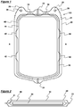
Figure 1 is a side elevation of a fluid concentration device which does not fall within the scope of the claimed invention; -
Figure 2 is a cross sectional view of the fluid concentration device ofFigure 1 , taken along axis A-A; -
Figure 3 is a side elevation of an embodiment of a fluid concentration device according to the first aspect of the invention; -
Figure 4 is a cross sectional view of the fluid concentration device ofFigure 3 , taken along axis B-B; and -
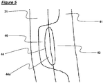
Figure 5 is a view on an enlarged scale of a fastening point where inner and outer bags of a fluid concentration device are fastened together. - Referring first to
Figures 1 and 2 , a fluid concentration device, which does not fall within the scope of the claimed invention, is generally designated 100. Thedevice 100 is for concentrating fluids comprising discrete or particulate material dispersed in a liquid medium by removal of a proportion of the liquid medium. Thedevice 100 comprises anouter bag 20 formed of a tough impermeable material, aninner bag 40 formed of a porous material and contained within theouter bag 20, and anabsorbent material 44 encapsulated within theinner bag 40. The outer bag has aninlet port 22, through which fluid may pass into thedevice 100 and entercavity 30 formed between theouter bag 20 and theinner bag 40, and anoutlet port 24, though which fluid may exit thedevice 100. - The presence of both an
inlet port 22 and anoutlet port 24 in theouter bag 20 enables fluid to flow though thedevice 100 continuously, allowing fluid concentration to be carried out as a continuous process. Fluid concentration may also be carried out in a batch process, in which thedevice 100 is charged with fluid via theinlet port 22, with theoutlet port 24 sealed. The fluid held in thedevice 100 may then be concentrated and subsequently drained from thedevice 100 by opening theoutlet port 24. However, it should be appreciated that other embodiments of thedevice 100 for concentrating fluid in a batch process may have only a single port through which fluid is both introduced into and drained from thedevice 100. - The
outer bag 20 is formed of polyvinylchloride (PVC) sheets and theinner bag 40 is formed of porous polycarbonate membrane. Both theouter bag 20 andinner bag 40 are formed by fastening two sheets of material together around their edges by heat welding. The material of theouter bag 20 is impermeable to the liquid medium of the fluid introduced into thedevice 100. The material of theinner bag 40 permits liquid medium, but not the discrete or particulate material, to pass through it and into the interior of theinner bag 40. For instance, where thedevice 100 is for producing blood cell concentrates from whole blood, theinner bag 40 is formed of material having pores with a maximum size of no greater than 5µm to permit blood plasma, but not red blood cells, to pass through. - The area around the edge of the
outer bag 20 where the two polyvinylchloride (PVC) sheets are welded together defines a weldedportion 21. This weldedportion 21 projects from each upper corner of theouter bag 20 to formextensions 26. Eachextension 26 has anaperture 28 to allow thedevice 100 to be hung from a suitable support. - The area around the edge of the
inner bag 40 where the two porous polycarbonate membranes are welded together also defines a weldedportion 41. Theabsorbent material 44 is entirely encapsulated by theinner bag 40. The weldedportion 41 around the edge of theinner bag 40 extends outwardly to form a number oftabs 42, which are fastened to the interior of theouter bag 20 at a number of points to suspend theinner bag 40 within the outer bag 20 (described in more detail below with reference toFigure 5 ). - In use, a fluid comprising discrete or particulate material dispersed in a liquid medium is introduced into the
device 100 through theinlet port 22 in theouter bag 20 and enters thecavity 30 between the outer 20 andinner bag 40. Theinlet 22 andoutlet 24 ports are then sealed to prevent the fluid escaping the device during the concentration process. Fluid contained incavity 30, passes through the porous walls of theinner bag 40 and is held there by theabsorbent material 44, thereby increasing the concentration of the discrete or particulate material in thecavity 30. Thedevice 100 may be gently agitated during the concentration process to facilitate passage of the liquid medium through the porous walls of theinner bag 40. Following concentration, the concentrated fluid contained incavity 30 may be drained from the device via theoutlet port 24, and the device disposed of. - Referring now to the
Figures 3 and 4 , an embodiment of a fluid concentration device according to the first aspect of the invention is generally designated 200. Thedevice 200 comprises anouter bag 20 formed of a tough impermeable material, aninner bag 40 formed of a porous material and contained within theouter bag 20, and awadding material 60 contained within theinner bag 40. - Both the
outer bag 20 and theinner bag 40 are formed by heat welding two sheets of material together in the weldedportions portion 21 at each upper corner of theouter bag 20form extensions 26, each having anaperture 28 to allow thedevice 200 to be hung from a suitable support. The weldedportion 41 of theinner bag 40 forms a number oftabs 42, which are fastened to the interior of theouter bag 20 at a number of points to suspend theinner bag 40 within the outer bag 20 (described in more detail below with reference toFigure 5 ). Thedevice 200 has aninlet port 22, through which fluid may enter thedevice 200, and adrainage port 52, through which concentrated fluid may be drained from thedevice 200. The presence of both aninlet port 22 and adrainage port 52 in theouter bag 20 enables fluid to flow though thedevice 100 continuously, allowing fluid concentration to be carried out as a continuous process. Fluid concentration may also be carried out in a batch process, in which thedevice 100 is charged with fluid via theinlet port 22, with theoutlet port 24 sealed. The fluid held in thedevice 100 may then be concentrated and subsequently drained from thedevice 100 by opening theoutlet port 24. However, it should be appreciated that other embodiments of thedevice 100 for concentrating fluid in a batch process may have only a single port through which fluid is both introduced into and drained from thedevice 100. - The
device 200 also has avacuum port 50, through which one end of avacuum conduit 54 enters thedevice 200 and connects directly with the interior of theinner bag 40. The other end of thevacuum conduit 54 is free to be connected to a source of reduced pressure such as a vacuum pump (not shown). Thevacuum conduit 54 is formed of a flexible plastics material and connects to theinner bag 40 via a coupling that is formed of a tough plastics material and comprises achannel portion 56, through with the drainage conduit communicates with the interior of theinner bag 40, and aflange portion 58, which contacts the surface of theinner bag 40 and provides an increased surface area to improve fastening with theinner bag 40. Theinner bag 40 is entirely sealed other than its connection with thedrainage conduit 54. - In use, a fluid comprising discrete or particulate material dispersed in a liquid medium is introduced into the
device 200 through theinlet port 22 and enters thecavity 30 formed between the outer 20 andinner bags 40. Theinlet port 22 anddrainage port 52 are then sealed to prevent the fluid escaping thedevice 200 during the concentration process. - The free end of the
vacuum conduit 54 is connected to a source of reduced pressure, which applies a reduced pressure to theinner bag 40. Thewadding material 60 prevents theinner bag 40 collapsing when the reduced pressure is applied, ensuring an even distribution of pressure throughout theinner bag 40. The reduced pressure draws liquid medium and any discrete or particulate material of a small enough diameter from thecavity 30, through the porous walls of theinner bag 40 into the interior of theinner bag 40. Liquid that enters theinner bag 40 is then drawn along thevacuum conduit 54 and into a receptacle (not shown) from which it can be collected. Particles that are too large to pass through the porous walls of theinner bag 40 remain in thecavity 30, resulting in those particles being concentrated in that portion of thedevice 200. Thedevice 200 may also be gently agitated during the concentration process to facilitate passage of the liquid medium through the porous walls of theinner bag 40. Following concentration, the concentrated fluid contained in thecavity 30 may be drained from thedevice 200 via thedrainage port 52, and thedevice 200 disposed of or re-used. - Referring now to
Figure 5 , a view on an enlarged scale of a fastening point between aninner bag 40 and anouter bag 20 is depicted. The fastening point comprises atab 42 having anopening 44 and a loop section 46. During manufacture of a device 100,200 according to this invention, the pre-formed inner bag is positioned between the two layers of material that form theouter bag 20. Thetabs 42 are located such that the loop section 46 and theouter region 44a of theaperture 44 are within the region that will become the weldedportion 21 of theouter bag 20. The two layers of theouter bag 20 weld together through theouter region 44a of theaperture 44, thereby encapsulating the loop section 46 within the weldedportion 21. Theinner bag 40 is therefore securely fastened to theouter bag 20 even where the material of theinner bag 40 and theouter bag 20 do not weld strongly to one another. - Specific embodiments of the invention, as defined in the original claims of the parent application, are the following:
- 1. A fluid concentration device comprising an outer bag formed of an impermeable material, an inner bag formed of a permeable material and containing an absorbent material, wherein the inner bag is fastened to, and suspended within, the outer bag.
- 2. The fluid concentration device according to preceding paragraph 1, wherein the absorbent material is a superabsorbent material.
- 3. The fluid concentration device according to preceding paragraph 2, wherein the superabsorbent material is a polyacrylate.
- 4. A fluid concentration device comprising an outer bag formed of an impermeable material and an inner bag formed of a permeable material, wherein the inner bag is adapted for connection to a source of reduced pressure.
- 5. The fluid concentration device according to preceding paragraph 4, wherein the inner bag is connected to the source of reduced pressure via a conduit.
- 6. The fluid concentration device according to preceding paragraph 4 or 5, wherein the inner bag contains a wadding material.
- 7. The fluid concentration device according to any of preceding paragraphs 4 to 6, wherein the inner bag is fastened to, and suspended within, the outer bag.
- 8. The fluid concentration device according to any preceding paragraph, wherein the materials of the inner and outer bags are flexible.
- 9. The fluid concentration device according to any preceding paragraph, wherein the materials of the inner and outer bags are heat weldable.
- 10. The fluid concentration device according to preceding paragraph 9, wherein the inner bag and the outer bag are formed of two sheets of material fastened together around their edges by heat welding.
- 11. The fluid concentration device according to any preceding paragraph, wherein the material of the outer bag is polyvinylchloride.
- 12. The fluid concentration device according to any preceding paragraph, wherein the material of the inner bag is porous polycarbonate membrane.
- 13. The fluid concentration device according to any preceding paragraph, wherein the pores of the inner bag have a diameter of between 0.01µm and 1mm, or between 0.01µm and 5µm, or between 0.1µm and 2µm, or about 1µm.
- 14. The fluid concentration device according to any of preceding paragraphs 1 to 3 and 7, wherein the inner bag is fastened to the inner wall of the outer bag at one or more fastening points.
- 15. The fluid concentration device according to preceding paragraph 14, wherein the one or more fastening points consist of a tab projecting from the edge of the inner bag and sandwiched between the two layers of the outer bag where they are welded together.
- 16. The fluid concentration device according to preceding paragraph 15, wherein each tab has one or more apertures.
- 17. Use of a fluid concentration device according to any preceding paragraph to produce a blood cell concentrate from whole blood.
- 18. A method of processing blood, which method comprises contacting blood with the first side of a porous screen having a first side and a second side, and applying a pressure differential across that porous screen, such that blood plasma is drawn through the porous screen.
- 19. A method of processing blood according to preceding paragraph 18, wherein the pressure differential is generated by connecting a pressure reducing means to the second side of the porous screen.
- 20. A method of processing blood according to preceding paragraph 19, wherein the pressure reducing means is a vacuum pump.
- 21. A method of processing blood according to any of preceding paragraphs 18 to 20, wherein the pressure differential is applied in conjunction with agitation.
- 22. A method of processing blood according to any of preceding paragraphs 18 to 21, wherein the pores of the porous screen have a diameter of up to 5µm, or up to 3µm, or up to 1µm.
- 23. A method of processing blood according to any of preceding paragraphs 18 to 22, further comprising a step of passing blood cell concentrate through a leukocyte reduction filter.
- 24. A method of processing blood according to any of preceding paragraphs 18 to 23, wherein the method further comprises a step of collecting the plasma that is drawn through the porous screen.
- 25. A method of processing blood according to any of preceding paragraphs 18 to 24, wherein the method is at least partially carried out within a device that houses the porous screen.
Claims (13)
- A fluid concentration device (200) for concentrating fluids comprising particulate material dispersed in a liquid medium by removal of a proportion of the liquid medium, the device comprising an outer bag (20) formed of an impermeable material and an inner bag (40) formed of a permeable material, characterised in that the device comprises a port (22) in the outer bag for introducing fluid into the cavity between the outer bag (20) and the inner bag (40), wherein the permeable material allows the liquid medium, but not the particulate material, to pass into the inner bag (40), and wherein the inner bag (40) contains a wadding material (60) and is adapted for connection to a source of reduced pressure.
- The fluid concentration device (200) of Claim 1, wherein the inner bag (40) is connected to the source of reduced pressure via a conduit (54).
- The fluid concentration device (200) of any preceding claim, wherein the inner bag (40) is fastened to, and suspended within, the outer bag (20).
- The fluid concentration device (200) of any preceding claim, wherein the materials of the inner and outer bags (40,20) are flexible.
- The fluid concentration device (200) of any preceding claim, wherein the materials of the inner and outer bags (40,20) are heat weldable.
- The fluid concentration device (200) of Claim 5, wherein the inner bag (40) and the outer bag (20) are formed of two sheets of material fastened together around their edges by heat welding.
- The fluid concentration device (200) of any preceding claim, wherein the material of the outer bag (20) is polyvinylchloride.
- The fluid concentration device (200) of any preceding claim, wherein the material of the inner bag (40) is porous polycarbonate membrane.
- The fluid concentration device (200) of any preceding claim, wherein the pores of the inner bag (40) have a diameter of between 0.01µm and 1mm, or between 0.01µm and 5µm, or between 0.1µm and 2µm, or about 1µm.
- The fluid concentration device (200) of Claim 3, wherein the inner bag (40) is fastened to the inner wall of the outer bag (20) at one or more fastening points.
- The fluid concentration device (200) of Claim 10, wherein the one or more fastening points consist of a tab (42) projecting from the edge of the inner bag (40) and sandwiched between the two layers of the outer bag (20) where they are welded together.
- The fluid concentration device (200) of Claim 11, wherein each tab (42) has one or more apertures (44).
- A method of processing blood, which method comprises the steps of:(i) introducing blood into the cavity between the outer bag (20) and the inner bag (40) of the fluid concentration device (200) of any one of Claims 1 to 12; and(ii) applying a pressure differential across the permeable material of the inner bag (40), such that blood plasma is drawn through the permeable material.
Applications Claiming Priority (4)
| Application Number | Priority Date | Filing Date | Title |
|---|---|---|---|
| GBGB0920070.0A GB0920070D0 (en) | 2009-11-17 | 2009-11-17 | Method of processing blood |
| GBGB0920072.6A GB0920072D0 (en) | 2009-11-17 | 2009-11-17 | Fluid concentrator |
| GBGB0920069.2A GB0920069D0 (en) | 2009-11-17 | 2009-11-17 | Reduced pressure fluid concentrator |
| EP10781993.0A EP2501419B1 (en) | 2009-11-17 | 2010-11-17 | Device for processing fluid |
Related Parent Applications (2)
| Application Number | Title | Priority Date | Filing Date |
|---|---|---|---|
| EP10781993.0A Division EP2501419B1 (en) | 2009-11-17 | 2010-11-17 | Device for processing fluid |
| EP10781993.0A Division-Into EP2501419B1 (en) | 2009-11-17 | 2010-11-17 | Device for processing fluid |
Publications (2)
| Publication Number | Publication Date |
|---|---|
| EP2921187A1 EP2921187A1 (en) | 2015-09-23 |
| EP2921187B1 true EP2921187B1 (en) | 2018-03-21 |
Family
ID=43590472
Family Applications (2)
| Application Number | Title | Priority Date | Filing Date |
|---|---|---|---|
| EP15163927.5A Active EP2921187B1 (en) | 2009-11-17 | 2010-11-17 | Device and method for processing fluid |
| EP10781993.0A Active EP2501419B1 (en) | 2009-11-17 | 2010-11-17 | Device for processing fluid |
Family Applications After (1)
| Application Number | Title | Priority Date | Filing Date |
|---|---|---|---|
| EP10781993.0A Active EP2501419B1 (en) | 2009-11-17 | 2010-11-17 | Device for processing fluid |
Country Status (6)
| Country | Link |
|---|---|
| US (1) | US9254354B2 (en) |
| EP (2) | EP2921187B1 (en) |
| AU (1) | AU2010320670B2 (en) |
| CA (1) | CA2766670C (en) |
| WO (1) | WO2011061533A1 (en) |
| ZA (1) | ZA201200068B (en) |
Families Citing this family (12)
| Publication number | Priority date | Publication date | Assignee | Title |
|---|---|---|---|---|
| GB2509780B (en) | 2013-01-15 | 2019-08-28 | Brightwake Ltd | Fat Processing Device |
| GB201313137D0 (en) * | 2013-07-23 | 2013-09-04 | Brightwake Ltd | Apparatus for blood concentration |
| US10159778B2 (en) | 2014-03-24 | 2018-12-25 | Fenwal, Inc. | Biological fluid filters having flexible walls and methods for making such filters |
| US10376627B2 (en) | 2014-03-24 | 2019-08-13 | Fenwal, Inc. | Flexible biological fluid filters |
| US9968738B2 (en) | 2014-03-24 | 2018-05-15 | Fenwal, Inc. | Biological fluid filters with molded frame and methods for making such filters |
| US9796166B2 (en) | 2014-03-24 | 2017-10-24 | Fenwal, Inc. | Flexible biological fluid filters |
| US9782707B2 (en) | 2014-03-24 | 2017-10-10 | Fenwal, Inc. | Biological fluid filters having flexible walls and methods for making such filters |
| US11724036B2 (en) | 2016-12-12 | 2023-08-15 | Orchid Holdings, Llc | Syringe for processing fat grafts and related methods |
| KR20190128186A (en) * | 2017-03-03 | 2019-11-15 | 리치 테크놀로지스 홀딩 컴퍼니 엘엘씨 | Apparatus for preserving blood preparations and cell cultures in a gas medium under pressure |
| GB2573265B (en) * | 2018-03-12 | 2022-06-15 | Tsi Tech Limited | Apparatus for treating blood |
| FR3106064A1 (en) * | 2020-01-14 | 2021-07-16 | Maco Pharma | System for the selective removal of a target substance in a biological fluid |
| JP6848108B1 (en) * | 2020-06-30 | 2021-03-24 | テルモ株式会社 | Medical bag system and centrifuge system |
Family Cites Families (34)
| Publication number | Priority date | Publication date | Assignee | Title |
|---|---|---|---|---|
| US3485751A (en) * | 1967-01-06 | 1969-12-23 | Walter L Herrmann | Dialyzer apparatus and method |
| US3742946A (en) | 1970-05-15 | 1973-07-03 | C Grossman | Apparatus for the in vivo treatment of blood containing harmful components resulting from chronic uremia and other conditions |
| SE441143B (en) | 1976-09-02 | 1985-09-16 | Hoechst Ag | MEMBRANE UNIT AND DEVICE FOR DISPOSAL OF BLOOD METABOLITES |
| DE2722025A1 (en) | 1977-05-16 | 1978-11-30 | Hoechst Ag | MEMBRANE UNIT, DEVICE WITH MEMBRANE UNIT, AND METHOD OF BLOOD PURIFICATION |
| DE3279765D1 (en) | 1981-07-22 | 1989-07-20 | Du Pont | Plasmapheresis by reciprocatory pulsatile filtration |
| US4631050A (en) | 1985-09-24 | 1986-12-23 | Reed Charles C | Autotransfusion system and method |
| FR2600537B1 (en) | 1986-06-24 | 1990-02-16 | Evelyne Lasnier | AUTOTRANSFUSER. |
| US4966758A (en) | 1988-04-15 | 1990-10-30 | Becton, Dickinson And Company | Vacuum ampule filtration device |
| IT1241940B (en) | 1989-11-09 | 1994-02-01 | Grace W R & Co | MULTICONCENTRATION DEVICE FOR DISPOSABLE LIQUIDS. |
| US5215519A (en) | 1990-03-07 | 1993-06-01 | Shettigar U Ramakrishna | Autotransfusion membrane system with means for providing reverse filtration |
| US5211850A (en) | 1991-07-26 | 1993-05-18 | Research Medical, Inc. | Plasma filter sorbent system for removal of components from blood |
| JPH0751487B2 (en) | 1993-05-10 | 1995-06-05 | 上野 素敬 | Antibacterial sheet and calendar using this sheet |
| GB9422504D0 (en) | 1994-11-08 | 1995-01-04 | Robertson Patricia M B | Blood testing |
| WO1997032653A1 (en) | 1996-03-08 | 1997-09-12 | Baxter Research Medical, Inc. | Selective membrane/sorption techniques for salvaging blood |
| WO1998019722A1 (en) | 1996-11-08 | 1998-05-14 | Pall Corporation | Method for purifying blood plasma and apparatus suitable therefor |
| US5876611A (en) | 1997-06-16 | 1999-03-02 | Shettigar; U. Ramakrishna | Intraoperative blood salvaging system and method |
| FR2777786B1 (en) | 1998-04-27 | 2000-08-11 | Maco Pharma Sa | FILTRATION POCKET FOR RETAINING THE CELLULAR PLASMA COMPONENTS BY FILTRATION, SET OF POCKETS CONTAINING THE SAME. |
| ES2293415T3 (en) | 1998-05-19 | 2008-03-16 | Terumo Kabushiki Kaisha | DEVICE FOR THE EXTRACTION OF LEUCOCITS. |
| US7641794B2 (en) | 2000-07-10 | 2010-01-05 | Asahi Kasei Medical Co., Ltd. | Blood processing filter |
| FR2814080B1 (en) | 2000-09-20 | 2003-02-28 | Maco Pharma Sa | FILTERING DEVICE WITH MULTIPLE FILTER MEDIA AND POCKET SYSTEM COMPRISING SAME |
| FR2821762B1 (en) | 2001-03-09 | 2003-11-28 | Maco Pharma Sa | FILTER UNIT COMPRISING TWO SEPARATE FILTER MEDIA AND POCKET SYSTEM COMPRISING SAME |
| AU2003213758A1 (en) * | 2002-03-14 | 2003-09-29 | Fenwal, Inc. | Compound removal device |
| FR2842122B1 (en) | 2002-07-10 | 2004-08-13 | Maco Pharma Sa | SELECTIVE DELEUCOCYTATION UNIT FOR A PLATELET PRODUCT |
| US7422726B2 (en) * | 2002-10-23 | 2008-09-09 | Blood Cell Storage, Inc. | Integrated container for lyophilization, rehydration and processing of biological materials |
| EP1579838A4 (en) | 2002-12-12 | 2007-11-28 | Asahi Chemical Ind | Virus-removing bag and virus-removing method using the same |
| US20040258765A1 (en) | 2003-06-23 | 2004-12-23 | Gee Gilbert C. | Method for treatment of sores and lesions of the skin |
| US20050186183A1 (en) * | 2003-12-08 | 2005-08-25 | Deangelo Joseph | Stabilized products, processes and devices for preparing same |
| US7332096B2 (en) | 2003-12-19 | 2008-02-19 | Fenwal, Inc. | Blood filter assembly having multiple filtration regions |
| TWI242460B (en) | 2003-12-23 | 2005-11-01 | Ind Tech Res Inst | Method and device for separating fibrin glue from blood plasma |
| FR2874327B1 (en) | 2004-08-19 | 2007-10-05 | Direction Et Priorites Sa Sa | AUTOTRANSFUSION METHOD AND PHASE SEPARATION AUTOTRANSFUSION DEVICE AND DETACHABLE POCKET CONCENTRATION |
| EP1848474B1 (en) | 2005-02-07 | 2013-06-12 | Hanuman LLC | Platelet rich plasma concentrate apparatus and method |
| EP1897570A1 (en) | 2006-09-08 | 2008-03-12 | Gelanus B.V. | Blood recuperation device and method |
| US20090300933A1 (en) * | 2008-06-04 | 2009-12-10 | William Howe | Dispensing vessel for clothes dryer |
| GB0809092D0 (en) | 2008-05-20 | 2008-06-25 | Univ Strathclyde | Fluid processing device |
-
2010
- 2010-11-17 EP EP15163927.5A patent/EP2921187B1/en active Active
- 2010-11-17 US US13/384,135 patent/US9254354B2/en active Active
- 2010-11-17 WO PCT/GB2010/051916 patent/WO2011061533A1/en active Application Filing
- 2010-11-17 AU AU2010320670A patent/AU2010320670B2/en not_active Ceased
- 2010-11-17 CA CA2766670A patent/CA2766670C/en active Active
- 2010-11-17 EP EP10781993.0A patent/EP2501419B1/en active Active
-
2012
- 2012-01-05 ZA ZA2012/00068A patent/ZA201200068B/en unknown
Non-Patent Citations (1)
| Title |
|---|
| None * |
Also Published As
| Publication number | Publication date |
|---|---|
| CA2766670A1 (en) | 2011-05-26 |
| WO2011061533A1 (en) | 2011-05-26 |
| ZA201200068B (en) | 2015-07-29 |
| US20120175319A1 (en) | 2012-07-12 |
| US9254354B2 (en) | 2016-02-09 |
| CA2766670C (en) | 2018-07-10 |
| AU2010320670B2 (en) | 2015-10-29 |
| EP2921187A1 (en) | 2015-09-23 |
| EP2501419B1 (en) | 2015-06-03 |
| EP2501419A1 (en) | 2012-09-26 |
| AU2010320670A1 (en) | 2012-02-02 |
Similar Documents
| Publication | Publication Date | Title |
|---|---|---|
| EP2921187B1 (en) | Device and method for processing fluid | |
| KR100743483B1 (en) | Virus-removing bag and virus-removing method using the same | |
| JP3517359B2 (en) | Cell separation / collection apparatus and cell separation / collection method | |
| AU2003204942B2 (en) | A selective deleukocytation unit for a platelet product | |
| CN1073614A (en) | Method and apparatus from the biological fluid separated plasma | |
| WO1993017774A1 (en) | Filter and method for obtaining platelets | |
| WO2010026891A1 (en) | Blood processing device | |
| TW201412350A (en) | Filter device | |
| EP2279239B1 (en) | Container having vortex breaker and system | |
| JP2011072816A (en) | Blood processing filter and filtering method of blood | |
| WO2016047444A1 (en) | Cell separation material and cell separation method | |
| JP2008086352A (en) | Blood processing filter | |
| AU2009248556B2 (en) | Fluid processing device | |
| JP4986285B2 (en) | Filtration method and apparatus for blood or blood components using leukocyte removal filter | |
| JP2008086353A (en) | Blood treatment filter and blood treatment method | |
| JP2007236665A (en) | Blood component separating apparatus and its usage | |
| JP2006158738A (en) | Centrifugal method of leukoreduction system | |
| JP2005237791A (en) | Method and system for filtering blood | |
| WO2017179705A1 (en) | Container for cell suspension preparation, and preparation method for cell suspension | |
| JPH03173824A (en) | Leukocyte separator | |
| JP5749123B2 (en) | Blood processing filter, blood processing system, and method for producing blood product | |
| JP5473730B2 (en) | Biological fluid filtration method | |
| JPH01224324A (en) | Leukocyte-separating material | |
| CN211462258U (en) | Negative pressure fat concentration closed separator | |
| JP2005137453A (en) | Blood treating filter |
Legal Events
| Date | Code | Title | Description |
|---|---|---|---|
| PUAI | Public reference made under article 153(3) epc to a published international application that has entered the european phase |
Free format text: ORIGINAL CODE: 0009012 |
|
| AC | Divisional application: reference to earlier application |
Ref document number: 2501419 Country of ref document: EP Kind code of ref document: P |
|
| AK | Designated contracting states |
Kind code of ref document: A1 Designated state(s): AL AT BE BG CH CY CZ DE DK EE ES FI FR GB GR HR HU IE IS IT LI LT LU LV MC MK MT NL NO PL PT RO RS SE SI SK SM TR |
|
| 17P | Request for examination filed |
Effective date: 20160321 |
|
| RBV | Designated contracting states (corrected) |
Designated state(s): AL AT BE BG CH CY CZ DE DK EE ES FI FR GB GR HR HU IE IS IT LI LT LU LV MC MK MT NL NO PL PT RO RS SE SI SK SM TR |
|
| 17Q | First examination report despatched |
Effective date: 20160616 |
|
| STAA | Information on the status of an ep patent application or granted ep patent |
Free format text: STATUS: EXAMINATION IS IN PROGRESS |
|
| GRAP | Despatch of communication of intention to grant a patent |
Free format text: ORIGINAL CODE: EPIDOSNIGR1 |
|
| STAA | Information on the status of an ep patent application or granted ep patent |
Free format text: STATUS: GRANT OF PATENT IS INTENDED |
|
| INTG | Intention to grant announced |
Effective date: 20171005 |
|
| GRAS | Grant fee paid |
Free format text: ORIGINAL CODE: EPIDOSNIGR3 |
|
| GRAA | (expected) grant |
Free format text: ORIGINAL CODE: 0009210 |
|
| STAA | Information on the status of an ep patent application or granted ep patent |
Free format text: STATUS: THE PATENT HAS BEEN GRANTED |
|
| AC | Divisional application: reference to earlier application |
Ref document number: 2501419 Country of ref document: EP Kind code of ref document: P |
|
| AK | Designated contracting states |
Kind code of ref document: B1 Designated state(s): AL AT BE BG CH CY CZ DE DK EE ES FI FR GB GR HR HU IE IS IT LI LT LU LV MC MK MT NL NO PL PT RO RS SE SI SK SM TR |
|
| REG | Reference to a national code |
Ref country code: GB Ref legal event code: FG4D |
|
| REG | Reference to a national code |
Ref country code: CH Ref legal event code: EP |
|
| REG | Reference to a national code |
Ref country code: AT Ref legal event code: REF Ref document number: 980411 Country of ref document: AT Kind code of ref document: T Effective date: 20180415 |
|
| REG | Reference to a national code |
Ref country code: IE Ref legal event code: FG4D |
|
| REG | Reference to a national code |
Ref country code: DE Ref legal event code: R096 Ref document number: 602010049432 Country of ref document: DE |
|
| REG | Reference to a national code |
Ref country code: SE Ref legal event code: TRGR |
|
| REG | Reference to a national code |
Ref country code: NL Ref legal event code: FP |
|
| PG25 | Lapsed in a contracting state [announced via postgrant information from national office to epo] |
Ref country code: NO Free format text: LAPSE BECAUSE OF FAILURE TO SUBMIT A TRANSLATION OF THE DESCRIPTION OR TO PAY THE FEE WITHIN THE PRESCRIBED TIME-LIMIT Effective date: 20180621 Ref country code: CY Free format text: LAPSE BECAUSE OF FAILURE TO SUBMIT A TRANSLATION OF THE DESCRIPTION OR TO PAY THE FEE WITHIN THE PRESCRIBED TIME-LIMIT Effective date: 20180321 Ref country code: LT Free format text: LAPSE BECAUSE OF FAILURE TO SUBMIT A TRANSLATION OF THE DESCRIPTION OR TO PAY THE FEE WITHIN THE PRESCRIBED TIME-LIMIT Effective date: 20180321 Ref country code: HR Free format text: LAPSE BECAUSE OF FAILURE TO SUBMIT A TRANSLATION OF THE DESCRIPTION OR TO PAY THE FEE WITHIN THE PRESCRIBED TIME-LIMIT Effective date: 20180321 Ref country code: FI Free format text: LAPSE BECAUSE OF FAILURE TO SUBMIT A TRANSLATION OF THE DESCRIPTION OR TO PAY THE FEE WITHIN THE PRESCRIBED TIME-LIMIT Effective date: 20180321 |
|
| REG | Reference to a national code |
Ref country code: LT Ref legal event code: MG4D |
|
| REG | Reference to a national code |
Ref country code: AT Ref legal event code: MK05 Ref document number: 980411 Country of ref document: AT Kind code of ref document: T Effective date: 20180321 |
|
| PG25 | Lapsed in a contracting state [announced via postgrant information from national office to epo] |
Ref country code: BG Free format text: LAPSE BECAUSE OF FAILURE TO SUBMIT A TRANSLATION OF THE DESCRIPTION OR TO PAY THE FEE WITHIN THE PRESCRIBED TIME-LIMIT Effective date: 20180621 Ref country code: GR Free format text: LAPSE BECAUSE OF FAILURE TO SUBMIT A TRANSLATION OF THE DESCRIPTION OR TO PAY THE FEE WITHIN THE PRESCRIBED TIME-LIMIT Effective date: 20180622 Ref country code: LV Free format text: LAPSE BECAUSE OF FAILURE TO SUBMIT A TRANSLATION OF THE DESCRIPTION OR TO PAY THE FEE WITHIN THE PRESCRIBED TIME-LIMIT Effective date: 20180321 Ref country code: RS Free format text: LAPSE BECAUSE OF FAILURE TO SUBMIT A TRANSLATION OF THE DESCRIPTION OR TO PAY THE FEE WITHIN THE PRESCRIBED TIME-LIMIT Effective date: 20180321 |
|
| REG | Reference to a national code |
Ref country code: FR Ref legal event code: PLFP Year of fee payment: 9 |
|
| PG25 | Lapsed in a contracting state [announced via postgrant information from national office to epo] |
Ref country code: PL Free format text: LAPSE BECAUSE OF FAILURE TO SUBMIT A TRANSLATION OF THE DESCRIPTION OR TO PAY THE FEE WITHIN THE PRESCRIBED TIME-LIMIT Effective date: 20180321 Ref country code: ES Free format text: LAPSE BECAUSE OF FAILURE TO SUBMIT A TRANSLATION OF THE DESCRIPTION OR TO PAY THE FEE WITHIN THE PRESCRIBED TIME-LIMIT Effective date: 20180321 Ref country code: AL Free format text: LAPSE BECAUSE OF FAILURE TO SUBMIT A TRANSLATION OF THE DESCRIPTION OR TO PAY THE FEE WITHIN THE PRESCRIBED TIME-LIMIT Effective date: 20180321 Ref country code: RO Free format text: LAPSE BECAUSE OF FAILURE TO SUBMIT A TRANSLATION OF THE DESCRIPTION OR TO PAY THE FEE WITHIN THE PRESCRIBED TIME-LIMIT Effective date: 20180321 Ref country code: IT Free format text: LAPSE BECAUSE OF FAILURE TO SUBMIT A TRANSLATION OF THE DESCRIPTION OR TO PAY THE FEE WITHIN THE PRESCRIBED TIME-LIMIT Effective date: 20180321 Ref country code: EE Free format text: LAPSE BECAUSE OF FAILURE TO SUBMIT A TRANSLATION OF THE DESCRIPTION OR TO PAY THE FEE WITHIN THE PRESCRIBED TIME-LIMIT Effective date: 20180321 |
|
| PG25 | Lapsed in a contracting state [announced via postgrant information from national office to epo] |
Ref country code: CZ Free format text: LAPSE BECAUSE OF FAILURE TO SUBMIT A TRANSLATION OF THE DESCRIPTION OR TO PAY THE FEE WITHIN THE PRESCRIBED TIME-LIMIT Effective date: 20180321 Ref country code: AT Free format text: LAPSE BECAUSE OF FAILURE TO SUBMIT A TRANSLATION OF THE DESCRIPTION OR TO PAY THE FEE WITHIN THE PRESCRIBED TIME-LIMIT Effective date: 20180321 Ref country code: SM Free format text: LAPSE BECAUSE OF FAILURE TO SUBMIT A TRANSLATION OF THE DESCRIPTION OR TO PAY THE FEE WITHIN THE PRESCRIBED TIME-LIMIT Effective date: 20180321 Ref country code: SK Free format text: LAPSE BECAUSE OF FAILURE TO SUBMIT A TRANSLATION OF THE DESCRIPTION OR TO PAY THE FEE WITHIN THE PRESCRIBED TIME-LIMIT Effective date: 20180321 |
|
| PG25 | Lapsed in a contracting state [announced via postgrant information from national office to epo] |
Ref country code: PT Free format text: LAPSE BECAUSE OF FAILURE TO SUBMIT A TRANSLATION OF THE DESCRIPTION OR TO PAY THE FEE WITHIN THE PRESCRIBED TIME-LIMIT Effective date: 20180723 |
|
| REG | Reference to a national code |
Ref country code: DE Ref legal event code: R097 Ref document number: 602010049432 Country of ref document: DE |
|
| PLBE | No opposition filed within time limit |
Free format text: ORIGINAL CODE: 0009261 |
|
| STAA | Information on the status of an ep patent application or granted ep patent |
Free format text: STATUS: NO OPPOSITION FILED WITHIN TIME LIMIT |
|
| PG25 | Lapsed in a contracting state [announced via postgrant information from national office to epo] |
Ref country code: DK Free format text: LAPSE BECAUSE OF FAILURE TO SUBMIT A TRANSLATION OF THE DESCRIPTION OR TO PAY THE FEE WITHIN THE PRESCRIBED TIME-LIMIT Effective date: 20180321 |
|
| 26N | No opposition filed |
Effective date: 20190102 |
|
| PG25 | Lapsed in a contracting state [announced via postgrant information from national office to epo] |
Ref country code: SI Free format text: LAPSE BECAUSE OF FAILURE TO SUBMIT A TRANSLATION OF THE DESCRIPTION OR TO PAY THE FEE WITHIN THE PRESCRIBED TIME-LIMIT Effective date: 20180321 |
|
| REG | Reference to a national code |
Ref country code: CH Ref legal event code: PL |
|
| PG25 | Lapsed in a contracting state [announced via postgrant information from national office to epo] |
Ref country code: LU Free format text: LAPSE BECAUSE OF NON-PAYMENT OF DUE FEES Effective date: 20181117 Ref country code: MC Free format text: LAPSE BECAUSE OF FAILURE TO SUBMIT A TRANSLATION OF THE DESCRIPTION OR TO PAY THE FEE WITHIN THE PRESCRIBED TIME-LIMIT Effective date: 20180321 |
|
| REG | Reference to a national code |
Ref country code: BE Ref legal event code: MM Effective date: 20181130 |
|
| REG | Reference to a national code |
Ref country code: IE Ref legal event code: MM4A |
|
| PG25 | Lapsed in a contracting state [announced via postgrant information from national office to epo] |
Ref country code: LI Free format text: LAPSE BECAUSE OF NON-PAYMENT OF DUE FEES Effective date: 20181130 Ref country code: CH Free format text: LAPSE BECAUSE OF NON-PAYMENT OF DUE FEES Effective date: 20181130 |
|
| PG25 | Lapsed in a contracting state [announced via postgrant information from national office to epo] |
Ref country code: IE Free format text: LAPSE BECAUSE OF NON-PAYMENT OF DUE FEES Effective date: 20181117 |
|
| PG25 | Lapsed in a contracting state [announced via postgrant information from national office to epo] |
Ref country code: BE Free format text: LAPSE BECAUSE OF NON-PAYMENT OF DUE FEES Effective date: 20181130 |
|
| PG25 | Lapsed in a contracting state [announced via postgrant information from national office to epo] |
Ref country code: MT Free format text: LAPSE BECAUSE OF NON-PAYMENT OF DUE FEES Effective date: 20181117 |
|
| PG25 | Lapsed in a contracting state [announced via postgrant information from national office to epo] |
Ref country code: TR Free format text: LAPSE BECAUSE OF FAILURE TO SUBMIT A TRANSLATION OF THE DESCRIPTION OR TO PAY THE FEE WITHIN THE PRESCRIBED TIME-LIMIT Effective date: 20180321 |
|
| PG25 | Lapsed in a contracting state [announced via postgrant information from national office to epo] |
Ref country code: MK Free format text: LAPSE BECAUSE OF NON-PAYMENT OF DUE FEES Effective date: 20180321 Ref country code: HU Free format text: LAPSE BECAUSE OF FAILURE TO SUBMIT A TRANSLATION OF THE DESCRIPTION OR TO PAY THE FEE WITHIN THE PRESCRIBED TIME-LIMIT; INVALID AB INITIO Effective date: 20101117 |
|
| PG25 | Lapsed in a contracting state [announced via postgrant information from national office to epo] |
Ref country code: IS Free format text: LAPSE BECAUSE OF FAILURE TO SUBMIT A TRANSLATION OF THE DESCRIPTION OR TO PAY THE FEE WITHIN THE PRESCRIBED TIME-LIMIT Effective date: 20180721 |
|
| PGFP | Annual fee paid to national office [announced via postgrant information from national office to epo] |
Ref country code: GB Payment date: 20230920 Year of fee payment: 14 |
|
| PGFP | Annual fee paid to national office [announced via postgrant information from national office to epo] |
Ref country code: NL Payment date: 20231009 Year of fee payment: 14 Ref country code: FR Payment date: 20230926 Year of fee payment: 14 |
|
| PGFP | Annual fee paid to national office [announced via postgrant information from national office to epo] |
Ref country code: SE Payment date: 20231011 Year of fee payment: 14 Ref country code: DE Payment date: 20231010 Year of fee payment: 14 |