EP2921035B1 - Reflector arrangement - Google Patents
Reflector arrangement Download PDFInfo
- Publication number
- EP2921035B1 EP2921035B1 EP13753605.8A EP13753605A EP2921035B1 EP 2921035 B1 EP2921035 B1 EP 2921035B1 EP 13753605 A EP13753605 A EP 13753605A EP 2921035 B1 EP2921035 B1 EP 2921035B1
- Authority
- EP
- European Patent Office
- Prior art keywords
- reflector
- fixing
- circuit board
- fixing element
- led circuit
- Prior art date
- Legal status (The legal status is an assumption and is not a legal conclusion. Google has not performed a legal analysis and makes no representation as to the accuracy of the status listed.)
- Active
Links
- 125000006850 spacer group Chemical group 0.000 claims description 13
- 230000013011 mating Effects 0.000 claims 6
- 238000004519 manufacturing process Methods 0.000 description 8
- 238000003780 insertion Methods 0.000 description 4
- 230000037431 insertion Effects 0.000 description 4
- 239000004020 conductor Substances 0.000 description 2
- 239000000463 material Substances 0.000 description 2
- 230000005855 radiation Effects 0.000 description 2
- XAGFODPZIPBFFR-UHFFFAOYSA-N aluminium Chemical compound [Al] XAGFODPZIPBFFR-UHFFFAOYSA-N 0.000 description 1
- 229910052782 aluminium Inorganic materials 0.000 description 1
- 230000015572 biosynthetic process Effects 0.000 description 1
- 230000001419 dependent effect Effects 0.000 description 1
- 238000006073 displacement reaction Methods 0.000 description 1
- 230000000694 effects Effects 0.000 description 1
- 238000005516 engineering process Methods 0.000 description 1
- 230000004313 glare Effects 0.000 description 1
- 238000002347 injection Methods 0.000 description 1
- 239000007924 injection Substances 0.000 description 1
- 238000009434 installation Methods 0.000 description 1
- 230000006641 stabilisation Effects 0.000 description 1
- 238000011105 stabilization Methods 0.000 description 1
Images


Classifications
-
- H—ELECTRICITY
- H05—ELECTRIC TECHNIQUES NOT OTHERWISE PROVIDED FOR
- H05K—PRINTED CIRCUITS; CASINGS OR CONSTRUCTIONAL DETAILS OF ELECTRIC APPARATUS; MANUFACTURE OF ASSEMBLAGES OF ELECTRICAL COMPONENTS
- H05K1/00—Printed circuits
- H05K1/02—Details
- H05K1/0274—Optical details, e.g. printed circuits comprising integral optical means
-
- F—MECHANICAL ENGINEERING; LIGHTING; HEATING; WEAPONS; BLASTING
- F21—LIGHTING
- F21V—FUNCTIONAL FEATURES OR DETAILS OF LIGHTING DEVICES OR SYSTEMS THEREOF; STRUCTURAL COMBINATIONS OF LIGHTING DEVICES WITH OTHER ARTICLES, NOT OTHERWISE PROVIDED FOR
- F21V17/00—Fastening of component parts of lighting devices, e.g. shades, globes, refractors, reflectors, filters, screens, grids or protective cages
- F21V17/005—Fastening of component parts of lighting devices, e.g. shades, globes, refractors, reflectors, filters, screens, grids or protective cages with keying means, i.e. for enabling the assembling of component parts in distinctive positions, e.g. for preventing wrong mounting
-
- F—MECHANICAL ENGINEERING; LIGHTING; HEATING; WEAPONS; BLASTING
- F21—LIGHTING
- F21V—FUNCTIONAL FEATURES OR DETAILS OF LIGHTING DEVICES OR SYSTEMS THEREOF; STRUCTURAL COMBINATIONS OF LIGHTING DEVICES WITH OTHER ARTICLES, NOT OTHERWISE PROVIDED FOR
- F21V19/00—Fastening of light sources or lamp holders
- F21V19/001—Fastening of light sources or lamp holders the light sources being semiconductors devices, e.g. LEDs
-
- F—MECHANICAL ENGINEERING; LIGHTING; HEATING; WEAPONS; BLASTING
- F21—LIGHTING
- F21V—FUNCTIONAL FEATURES OR DETAILS OF LIGHTING DEVICES OR SYSTEMS THEREOF; STRUCTURAL COMBINATIONS OF LIGHTING DEVICES WITH OTHER ARTICLES, NOT OTHERWISE PROVIDED FOR
- F21V7/00—Reflectors for light sources
- F21V7/0083—Array of reflectors for a cluster of light sources, e.g. arrangement of multiple light sources in one plane
-
- H—ELECTRICITY
- H05—ELECTRIC TECHNIQUES NOT OTHERWISE PROVIDED FOR
- H05K—PRINTED CIRCUITS; CASINGS OR CONSTRUCTIONAL DETAILS OF ELECTRIC APPARATUS; MANUFACTURE OF ASSEMBLAGES OF ELECTRICAL COMPONENTS
- H05K3/00—Apparatus or processes for manufacturing printed circuits
- H05K3/0058—Laminating printed circuit boards onto other substrates, e.g. metallic substrates
- H05K3/0061—Laminating printed circuit boards onto other substrates, e.g. metallic substrates onto a metallic substrate, e.g. a heat sink
-
- F—MECHANICAL ENGINEERING; LIGHTING; HEATING; WEAPONS; BLASTING
- F21—LIGHTING
- F21Y—INDEXING SCHEME ASSOCIATED WITH SUBCLASSES F21K, F21L, F21S and F21V, RELATING TO THE FORM OR THE KIND OF THE LIGHT SOURCES OR OF THE COLOUR OF THE LIGHT EMITTED
- F21Y2105/00—Planar light sources
- F21Y2105/10—Planar light sources comprising a two-dimensional array of point-like light-generating elements
-
- F—MECHANICAL ENGINEERING; LIGHTING; HEATING; WEAPONS; BLASTING
- F21—LIGHTING
- F21Y—INDEXING SCHEME ASSOCIATED WITH SUBCLASSES F21K, F21L, F21S and F21V, RELATING TO THE FORM OR THE KIND OF THE LIGHT SOURCES OR OF THE COLOUR OF THE LIGHT EMITTED
- F21Y2115/00—Light-generating elements of semiconductor light sources
- F21Y2115/10—Light-emitting diodes [LED]
-
- H—ELECTRICITY
- H05—ELECTRIC TECHNIQUES NOT OTHERWISE PROVIDED FOR
- H05K—PRINTED CIRCUITS; CASINGS OR CONSTRUCTIONAL DETAILS OF ELECTRIC APPARATUS; MANUFACTURE OF ASSEMBLAGES OF ELECTRICAL COMPONENTS
- H05K2201/00—Indexing scheme relating to printed circuits covered by H05K1/00
- H05K2201/09—Shape and layout
- H05K2201/09009—Substrate related
- H05K2201/09063—Holes or slots in insulating substrate not used for electrical connections
-
- H—ELECTRICITY
- H05—ELECTRIC TECHNIQUES NOT OTHERWISE PROVIDED FOR
- H05K—PRINTED CIRCUITS; CASINGS OR CONSTRUCTIONAL DETAILS OF ELECTRIC APPARATUS; MANUFACTURE OF ASSEMBLAGES OF ELECTRICAL COMPONENTS
- H05K2201/00—Indexing scheme relating to printed circuits covered by H05K1/00
- H05K2201/10—Details of components or other objects attached to or integrated in a printed circuit board
- H05K2201/10007—Types of components
- H05K2201/10106—Light emitting diode [LED]
-
- H—ELECTRICITY
- H05—ELECTRIC TECHNIQUES NOT OTHERWISE PROVIDED FOR
- H05K—PRINTED CIRCUITS; CASINGS OR CONSTRUCTIONAL DETAILS OF ELECTRIC APPARATUS; MANUFACTURE OF ASSEMBLAGES OF ELECTRICAL COMPONENTS
- H05K2201/00—Indexing scheme relating to printed circuits covered by H05K1/00
- H05K2201/10—Details of components or other objects attached to or integrated in a printed circuit board
- H05K2201/10007—Types of components
- H05K2201/10121—Optical component, e.g. opto-electronic component
-
- H—ELECTRICITY
- H05—ELECTRIC TECHNIQUES NOT OTHERWISE PROVIDED FOR
- H05K—PRINTED CIRCUITS; CASINGS OR CONSTRUCTIONAL DETAILS OF ELECTRIC APPARATUS; MANUFACTURE OF ASSEMBLAGES OF ELECTRICAL COMPONENTS
- H05K2201/00—Indexing scheme relating to printed circuits covered by H05K1/00
- H05K2201/10—Details of components or other objects attached to or integrated in a printed circuit board
- H05K2201/10431—Details of mounted components
- H05K2201/10598—Means for fastening a component, a casing or a heat sink whereby a pressure is exerted on the component towards the PCB
Definitions
- the invention relates to a reflector assembly according to the preamble of patent claim 1.
- Reflector arrangements with LED printed circuit boards arranged on a main body and reflectors arranged thereon are known from the prior art.
- the object of the present invention is to provide a reflector arrangement which enables positioning of a reflector in the most accurate possible manner.
- the reflector assembly comprises a base body which has a receiving region for receiving at least one LED printed circuit board, at least one LED printed circuit board which is arranged in the receiving region of the base body and has at least one recess, and at least one reflector element which has a first connecting element.
- the reflector arrangement comprises at least one fixing element with an upper and a lower side, wherein the upper side is arranged at a distance from the lower side, and wherein the lower side has a second connecting element which has a longitudinal extent in a longitudinal direction in the direction from the upper side to the lower side , Furthermore, the upper side of the fixing element has a depression in the longitudinal direction on.
- the second connection element of the fixing element and the recess of the LED circuit board are designed such that the second connection element can be inserted into the recess of the LED circuit board, so that the underside of the fixing element can be contacted with the circuit board.
- the depression of the upper side of the fixing element and the first connection element of the reflector element are designed such that the first connection element of the reflector element can be introduced into the depression of the upper side of the fixing element, so that the reflector element can be contacted with the upper side of the fixing element.
- the fixing element of the reflector arrangement according to the invention thus makes it possible, on the one hand, to observe a predetermined distance between a reflector element and an LED printed circuit board.
- the fixing element may for example be designed so that the distance between its top and its bottom is compliant with predetermined standards.
- a reflector element can be fixed to an LED printed circuit board at a defined location by the fixing element.
- a positioning of a reflector element in extremely accurate manner is made possible by the fixing.
- the fixing but also has a variety of other advantages.
- a reflector element can also be placed at a position on the top of the fixing, so that at this point by the fixing a distance from the LED circuit board is specified, and the reflector element this applied position is movable in at least one direction.
- a plurality of fixing element can be made possible, for example, that the reflector element is fixable by means of a fixing and can be placed at another location on another fixing, so that different manufacturing tolerances or thermal expansions can be taken into account.
- the fixing of the reflector assembly according to the invention has in contrast to, for example, integrally formed with a reflector element spacers also has the advantage that an orientation of the fixing element is independent of the reflector element possible. This provides further very advantageous possibilities of positioning and fixing, which will be explained in more detail below.
- the second connection element on the underside of the fixing element has a cylindrical basic shape, and the recess of the LED circuit board is cylindrical in such a way that the fixing element is inserted in the recess of the LED circuit board second connecting element in the direction the longitudinal direction extending axis is rotatable.
- the recess of the fixing element can be designed so that insertion of the first connecting element of the reflector element is only possible if they have a certain angular position to each other to allow by the fixing an alignment of the reflector element.
- rotation of the fixing in the cylindrical Recess of the LED circuit board so a corresponding orientation can be made much easier and more accurate than, for example, by rotation of the reflector element itself.
- the fixing element has an outer side which is arranged between the upper side and the lower side of the fixing element, wherein a hook-shaped connecting piece is arranged on the outer side.
- the base body has at least one counterpart element, which is designed such that the hook-shaped connecting piece can be hooked into the counterpart element.
- the hook-shaped connector can be done so an additional lateral fixation of the fixing.
- an additional fixing point of the fixing element is provided by the possibility of hooking into a counterpart element, which allows an even more accurate and stable alignment of the fixing element and thus also of the reflector element.
- this provides the opportunity to fix the LED circuit board.
- the fixing in particular by inserting the first connecting element in the recess of the LED circuit board and by hooking the hook-shaped connecting element of the fixing element in the counterpart element of the base body at the same time a fixing or fixing of the LED circuit board on the main body are accomplished.
- the counterpart element of the body is at least partially disposed along the receiving area of the LED circuit board.
- the counterpart element is preferably designed such that the hook-shaped connecting piece of the fixing element can be hooked into the counterpart element by rotating the fixing element about the axis extending in the direction of the longitudinal extension direction into the counterpart element when the second connecting element of the underside of the fixing element is inserted into the recess of the LED printed circuit board.
- This is a particularly easy-to-use way to hook the fixing in the counterpart element.
- a desirable desirable compact design of the reflector assembly and the fixing element is kept relatively small, so that the hooking represents by rotation of the fixing a particularly elegant attachment and Justageberichteit the fixing.
- the depression of the upper side of the fixing element and the first connection element of the reflector element may be round in a cross-section perpendicular to the direction of longitudinal extension so that the reflector element is rotatable about an axis extending in the direction of the longitudinal extension when the first connection element is inserted into the depression.
- the first connecting element of the reflector element may be formed as an index cylinder, so that upon insertion of this cylinder into the recess, the reflector element is so far rotatable until the index or indices engage in notches or recesses provided recess of the fixing.
- the upper side of the fixing element has a straight-line groove perpendicular to the direction of longitudinal extension
- the reflector element has a slide element which is designed such that it can be inserted into the groove
- a precise alignment of the reflector element is made possible.
- a fixation of the reflector element on the LED board at a certain point can be accomplished by, for example, a first fixing and by providing another such fixing the reflector can be aligned and fixed in a direction perpendicular to the groove. Due to the mobility of the reflector element in the direction of the groove in the positioning of the reflector element and manufacturing tolerances and different thermal expansion, in particular of the reflector element, are taken into account.
- the outer side of the fixing element is formed at least in one area as a flat surface, so that the fixing element can be aligned by means of this flat surface on the counterpart element of the main body.
- This flat surface can rest on the rectilinear counterpart element of the base body, for example, when introduced into the recess of the LED printed circuit board second connecting element of the fixing.
- the groove of the upper side of the fixing element can run parallel to this flat surface of the outer side, so that the reflector element can also be aligned parallel to the counterpart element with the slide element which can be inserted into the groove.
- the recess of the LED circuit board should be positioned in the circuit board such that the recess has such a distance from the counterpart element of the base body, that the flat surface of the outer side of the fixing element inserted into the recess of the LED circuit board second connecting element, the counterpart element of the body contacted.
- fixing elements which are used for guiding the carriage member of the reflector element by means of the groove, are so arranged with the second connection element in the recess of the LED circuit board, that they, due to the contacting of their flat surface with the counterpart element of the base body, are not rotatable, and that fixing elements for the introduction of the second connecting element of the reflector element are to be used, are rotatable.
- a stop element is arranged on the outside of the fixing element, by means of which the fixing element is rotatable when inserted into the recess of the LED circuit board second connecting element to a predetermined position.
- the outside of the fixing element can, for example, be configured substantially round with a flat surface arranged in a region, as described above, and the stop element, which is designed, for example, as a protrusion from the outside.
- the fixing element can be inserted into the recess of the LED circuit board and then rotated to hook the hook-shaped connecting element in the counterpart element of the body until the stop element contacts the counterpart element and thus prevents further rotation of the fixing.
- the fixing can be very precisely turned exactly until the hooked position is taken.
- the reflector element comprises spacer elements with a predetermined length in the longitudinal direction, so that when inserted into the recess of the top of the fixing element first connecting element of the reflector element and inserted into the recess of the LED circuit board second connecting element of the fixing element, the spacer elements contact the LED circuit board.
- the spacer elements are preferably arranged so that they contact in contact with the LED circuit board in areas in which no conductor tracks extend.
- the reflector element comprises snap-action elements, which are designed to snap in on reflector elements arranged on the LED printed circuit board under bearing surfaces of the base body, which are arranged at least partially along the receiving region of the LED printed circuit board.
- snap elements allow additional support, stabilization and / or fixation of the reflector element on the base body.
- the snap elements can be designed as Schnapphacken that snap under the arranged on both sides of the receiving area bearing surfaces.
- the contact surfaces can also be identical to the counterpart elements of the body, which can extend in particular rail-shaped on both sides along the receiving area of the body.
- Fig. 1 shows a schematic representation of an arranged on a base body 12 LED printed circuit board 14 for a reflector assembly 10 (see. Fig. 6-8 ) according to an embodiment of the invention.
- the main body 12 has a receiving area 16, in which the LED printed circuit board 14 is arranged.
- the receiving region 16 may be formed as a depression in the base body surface.
- a plurality of LEDs 18 is arranged, on each of which a single reflector 48 (see. Fig. 5a ) should be arranged.
- a single reflector 48 see. Fig. 5a
- the LED circuit board 14 here has two recesses 22, in which fixing elements 26 (see. Fig.
- These two recesses 22 preferably have the same distance to the edge of the receiving area 16, ie in particular to the counterpart element 20 running on the edge.
- an index 24 introduced in the form of a circular segment-like recess. This index 24 serves for a fixing element 26 to be rotatable with a second connecting element 44 inserted into the recess 22 of the LED printed circuit board 14, while a fixing element 26 introduced into the right-hand recess 22 is not rotatable.
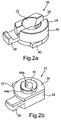
- Fig. 2a shows a schematic representation of a first perspective view of a fixing element 26 for a reflector assembly 10 according to an embodiment of the invention.
- the fixing element 26 is designed here as a rotary latch and has, in particular, a top side 28 and a bottom side 30 (cf. Fig. 2b ) on.
- the upper side 28 has a recess 32 which is frusto-conical here with a cylindrical continuation in the longitudinal direction. In this case, the direction from the upper side 28 of the fixing element 26 to the lower side 30 is referred to as the longitudinal direction of extension.
- the upper side 28 of the fixing element 26 has a rectilinear groove 34. This runs in this example centrally through the recess 32, but can generally be elsewhere.
- a hook-shaped connecting piece 38 is arranged on the outer side 36 of the fixing element 26 for engagement in a counterpart element 20 of the base body 12.
- a stop element 40 is still arranged, which protrudes on the substantially cylindrical outer side 36.
- the outer side 36 of the fixing element 26 is substantially cylindrical in that, in one region, it has a side formed as a flat surface 42 (cf. Fig. 2b ).
- Fig. 2b shows a schematic representation of a second perspective view of the fixing member 26 Fig. 2a , In particular, this representation is 180 ° opposite from Fig. 2a turned.
- the fixing element 26 comprises the same elements as in FIG Fig. 2a described.
- the second connecting element 44 can be seen on the underside 30 of the fixing element 26. This is preferably cylindrical in shape to be inserted into a cylindrical recess 22 of the LED circuit board 14.
- the second connecting element 44 may also be formed of cylindrical elements, such as two half-cylinders, and have recesses 44a and / or elevations 44b, for example, with appropriate design of the recess 22 of the LED circuit board 14 to allow a snap into a locked position.
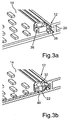
- Fig. 3a shows a schematic representation of a arranged on the LED printed circuit board 14 and the base body 12 fixing element 26 for a reflector assembly 10 according to an embodiment of the invention.
- Good to see here is formed as a recess of the body 12 receiving portion 16 for the LED circuit board 14 and the rail-shaped counterpart element 20 which extends rectilinear and laterally at the edge of the receiving area 16.
- the fixing element 26 shown here is in an hooked position.
- the arranged on the outer side 36 of the fixing member 26 hook-shaped connector 38 engages in the counterpart element 20 of the body 12.
- the fixing member 26 is inserted with its second connecting element 44 in the recess 22 of the LED circuit board 14 and indeed in a recess 22 as they in Fig.
- the fixing element 26 can first be inserted into the recess 22 of the LED circuit board 14, wherein the index 24 so sogt that the fixing element 26 is not applied to the counterpart element 20 or this contacted and thus the fixing member 26 can be rotated, in particular about a longitudinal axis extending along the axis.
- the hook-shaped connecting piece 38 can be hooked into the counterpart element 20 and in the as in Fig. 3a shown position.
- the stop element 40 of the fixing element 26 ensures that this position is very high can be taken precisely.
- Fig. 3b shows again in Fig. 3a
- the recess 32 of the top 28 of the fixing member 26 may be formed as a continuous hole extending from the top 28 to the bottom 30 and manufacturing technology particularly simple and inexpensive is.
- the LED printed circuit board 14 is clamped between the fixing element 26 and the base body 12 and thus fixed to the base body 12.
- Fig. 4 shows a schematic representation of two arranged on the LED printed circuit board 14 fixing elements 26 in different positions for a reflector assembly 10 according to an embodiment of the invention.
- the arrangement shown corresponds to the in Fig. 1 illustrated arrangement of the LED circuit board 14 on the base body 12 with now inserted into the two recesses 22 of the LED circuit board 14 second connecting elements 44 of the two illustrated fixing elements 26th
- the fixing element 26 is positioned such that the hook-shaped connecting piece 38 hooks into the counterpart element 20 of the base body 12. This can be done by inserting the fixing element 26 in the recess 22 and turning the fixing member 26 in the hooked position.
- the rotation of the fixing element 26 is characterized by the in Fig. 1 shown index 24 in the counterpart element 20 allows.
- the fixing element 26 is also provided with a stop element 40.
- the first connecting element 50 of the reflector element 46 can be inserted, whereby a point of the reflector element 46 is defined, positioned and fixed.
- the fixing element 26 is positioned such that the flat surface 42 of the outer side 36 of the fixing element 26 bears against the counterpart element 20.
- the groove 34 extending in the upper side 28 of the fixing element 26 is arranged parallel to the flat surface 42 and thus also parallel to the counterpart element 20. This groove 34 allows the reception of a slide element 52 arranged on the reflector element 46 so that the reflector element 46 is precisely parallel to the counterpart element 20 can be aligned.
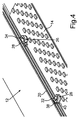
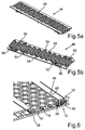
- Fig. 5a shows a schematic representation of a plan view of a reflector element 46 and Fig. 5b a schematic representation of a bottom view of this reflector element 46 for a reflector assembly 10 according to an embodiment of the invention.
- the reflector element 46 in this case comprises a plurality of individual reflectors 48, which are arranged in particular such that each individual reflector 48 is associated with an LED 18 of the LED circuit board 14.
- the geometric configuration of the arrangement of the individual reflectors 48 is thus identical to the geometric configuration of the LED arrangement on the LED printed circuit board 14.
- the reflector element 46 further comprises, in particular on its underside or the side which, when arranged on the LED printed circuit board 14th this is facing, a first connecting element 50 which is inserted into the recess 32 of a fixing member 26 and is formed in this case as an index cylinder. Furthermore, the reflector element 46 has a slide element 52 in order to engage in the groove 34 of a fixing element 26. In addition, spacer elements 54 are still arranged on the reflector element 46, by means of which the reflector element 46 rests on the LED printed circuit board 14 in this arrangement.
- FIGS. 7 and 8 each show a schematic representation of a cross section through a reflector assembly 10 according to embodiments of the invention.
- the reflector element 46 is fixed by the fixing elements 26 on the LED circuit board 14 and precisely positioned, in particular so that each individual reflector 48 as closely as possible via an LED 18 in a predetermined and in particular by the fixing elements 26 and spacers 54 certain distance is arranged
- Fig. 6 shows a cross section through a fixing element 26, in the recess 32, the first connecting element 50 of the reflector element 46 is inserted
- Fig. 7 shows a cross section through a fixing element 26, in the groove 34, a slide member 52 of the reflector element 46 is inserted
- FIG. 8 a cross section with a spacer element 54 shown of the reflector element 46 in order to support this in addition to the LED circuit board 14 and to keep in a predefined distance.
- the fixing elements 26 and the spacer elements 54 are arranged in such a way that they maintain a certain distance from the printed conductors 58 running on the LED printed circuit board 14.
- Fig. 9 shows a schematic representation of a reflector assembly 10 with a plurality of LED printed circuit boards 14, in particular two, and a plurality of reflector elements 46, in particular 4, according to an embodiment of the invention.
- the base body 12 has a receiving region 16, in which a plurality of LED printed circuit boards 14 are arranged.
- a plurality of fixing elements 26 for positioning the reflector elements 46 are arranged in each LED circuit board 14 .
- the reflector elements 46 can thus be plugged onto the LED printed circuit boards 14, preferably in such a way that a first connecting element 50 of a reflector element 46 is inserted into a recess 32 of a fixing element 26 and the slide element 52 of the reflector element 46 into the groove 34 of a further fixing element 26 is introduced.
- each fixing element 26 must have a groove 34, and it is also possible, for example, to provide only every second fixing element 26 with a groove 34 in the upper side 28.
- the base body 12 may further be an extruded aluminum profile and the reflector elements 46 may be metallized plastic injection molded parts. These designs are particularly easy to manufacture and particularly cost-effective options.
- Such a reflector arrangement which enables a positioning of a reflector with respect to an LED arrangement in an extremely accurate manner.
- a positioning is made possible, which can ensure the prescribed safety distances and is so accurate that there are no negative influences on the radiation characteristics.
- the thermally different expansion of the individual materials and the manufacturing tolerances can be accommodated by this reflector arrangement. All this is made possible by the provision of a fixing element, which can be arranged between the reflector and the LED circuit board.
- This fixing element can be used on the one hand to the reflector element at a defined To fix point on the LED circuit board and at the same time, such a fixing element can also be used to align the reflector element, so that the reflector element still remains movable in one direction to intercept manufacturing tolerances and thermal expansions can.
- fixing the fixing of the LED circuit board on the body can be made possible at the same time still.
- the reflector arrangement described here makes it possible to define the position of the boards and thus of the LEDs relative to the receptacle and the reflector element.
- the reflector assembly can be implemented at low cost and with low installation costs. Furthermore, it is still a very low height and thus realize a very flat body.
Description
Die Erfindung geht aus von einer Reflektoranordnung nach dem Oberbegriff des Patentanspruchs 1.The invention relates to a reflector assembly according to the preamble of patent claim 1.
Aus dem Stand der Technik sind Reflektoranordnungen mit an einem Grundkörper angeordneten LED-Leiterplatten und daran angeordneten Reflektoren bekannt.Reflector arrangements with LED printed circuit boards arranged on a main body and reflectors arranged thereon are known from the prior art.
Beispielsweise zeigen
Um LED-Leuchten beispielsweise als Büroleute verwenden zu können, müssen bestimmte Richtlinien und Normen eingehalten werden, wie beispielsweise Normen zur Einhaltung der Bildschirmarbeitsplatztauglichkeit. Dementsprechend sind u.a. bestimmte Anforderungen an die seitliche Entblendung der LED-Leuchten zu stellen. Um diesen Anforderungen gerecht werden zu können und eine bestimmte Abstrahlcharakteristik einer solchen Leuchte zu erreichen, sind bestimmte Optiken oder Reflektoren erforderlich. Das Hauptproblem jedoch bei der Verwendung von Reflektoren oder Reflektorrastern ist dabei die Positionierung eines solchen Reflektors über den LEDs. Bei einer derartigen Positionierung müssen vorgeschriebene Sicherheitsabstände gewährleistet werden und zum anderen muss die Positionierung auch derart akkurat sein, dass sich keine negativen Einflüsse auf die Abstrahlcharakteristik ergeben. Dabei ergeben sich weitere Probleme, wie die unterschiedliche thermische Ausdehnung der einzelnen Materialien sowie Ungenauigkeiten in der Anordnung bedingt durch Fertigungstoleranzen, denen ebenfalls Rechnung getragen werden muss.For example, to use LED lights as office people, certain guidelines and standards must be adhered to, such as compliance with VDU workstation standards. Accordingly, certain requirements are to be placed on the side glare of the LED lights. In order to meet these requirements and to achieve a certain emission characteristics of such a luminaire, certain optics or reflectors are required. However, the main problem with the use of reflectors or Reforrorrastern is the positioning of such a reflector over the LEDs. In such a positioning prescribed safety distances must be guaranteed and on the other hand, the positioning must also be so accurate that there are no negative effects on the radiation characteristics. there arise further problems, such as the different thermal expansion of the individual materials and inaccuracies in the arrangement due to manufacturing tolerances, which must also be taken into account.
Die Aufgabe der vorliegenden Erfindung ist es, eine Reflektoranordnung bereitzustellen, welche eine Positionierung eines Reflektors in möglichst akkurater Weise ermöglicht.The object of the present invention is to provide a reflector arrangement which enables positioning of a reflector in the most accurate possible manner.
Diese Aufgabe wird gelöst durch eine Reflektoranordnung mit den Merkmalen des Patentanspruchs 1.This object is achieved by a reflector arrangement having the features of patent claim 1.
Besonders vorteilhafte Ausgestaltungen finden sich in den abhängigen Ansprüchen.Particularly advantageous embodiments can be found in the dependent claims.
Die erfindungsgemäße Reflektoranordnung umfasst einen Grundkörper, welcher einen Aufnahmebereich zur Aufnahme mindestens einer LED-Leiterplatte aufweist, mindestens eine LED-Leiterplatte, welche im Aufnahmebereich des Grundkörpers angeordnet ist und mindestens eine Aussparung aufweist, und mindestens ein Reflektorelement, welches ein erstes Verbindungselement aufweist. Des Weiteren umfasst die Reflektoranordnung mindestens ein Fixierelement mit einer Ober- und einer Unterseite, wobei die Oberseite in einem Abstand zur Unterseite angeordnet ist, und wobei die Unterseite ein zweites Verbindungselement aufweist, das eine Längserstreckung in einer Längserstreckungsrichtung in Richtung von der Oberseite zur Unterseite aufweist. Weiterhin weist die Oberseite des Fixierelements eine Vertiefung in der Längserstreckungsrichtung auf. Dabei sind das zweite Verbindungselement des Fixierelements und die Aussparung der LED-Leiterplatte derart ausgebildet, dass das zweite Verbindungselement in die Aussparung der LED-Leiterplatte einführbar ist, so dass die Unterseite des Fixierelements mit der Leiterplatte kontaktierbar ist. Weiterhin sind die Vertiefung der Oberseite des Fixierelements und das erste Verbindungselement des Reflektorelement derart ausgebildet, dass in die Vertiefung der Oberseite des Fixierelements das erste Verbindungselement des Reflektorelements einführbar ist, so dass das Reflektorelement mit der Oberseite des Fixierelements kontaktierbar ist.The reflector assembly according to the invention comprises a base body which has a receiving region for receiving at least one LED printed circuit board, at least one LED printed circuit board which is arranged in the receiving region of the base body and has at least one recess, and at least one reflector element which has a first connecting element. Furthermore, the reflector arrangement comprises at least one fixing element with an upper and a lower side, wherein the upper side is arranged at a distance from the lower side, and wherein the lower side has a second connecting element which has a longitudinal extent in a longitudinal direction in the direction from the upper side to the lower side , Furthermore, the upper side of the fixing element has a depression in the longitudinal direction on. In this case, the second connection element of the fixing element and the recess of the LED circuit board are designed such that the second connection element can be inserted into the recess of the LED circuit board, so that the underside of the fixing element can be contacted with the circuit board. Furthermore, the depression of the upper side of the fixing element and the first connection element of the reflector element are designed such that the first connection element of the reflector element can be introduced into the depression of the upper side of the fixing element, so that the reflector element can be contacted with the upper side of the fixing element.
Durch das Fixierelement der erfindungsgemäße Reflektoranordnung wird es somit zum einen ermöglicht, einen vorgegebenen Abstand zwischen einem Reflektorelement und einer LED-Leiterplatte einzuhalten. Das Fixierelement kann dabei beispielsweise so ausgebildet sein, dass der Abstand zwischen seiner Ober- und seiner Unterseite mit vorgegebenen Normen konform ist. Darüber hinaus kann durch das Fixierelement ein Reflektorelement an einer LED-Leiterplatte an einer definierten Stelle fixiert werden. So wird durch das Fixierelement eine Positionierung eines Reflektorelements in äußerst akkurater Weise ermöglicht. Das Fixierelement hat aber darüber hinaus noch eine Vielzahl an weiteren Vorteilen. Es muss nicht zwingend ein erstes Verbindungselement eines Reflektorelements in die Vertiefung des Fixierelements eingeführt werden, ein Reflektorelement kann auch an einer Stelle auf die Oberseite des Fixierelement auflegbar sein, so dass an dieser Stelle durch das Fixierelement ein Abstand zur LED-Leiterplatte vorgegeben ist, und das Reflektorelement an dieser aufgelegten Stelle zumindest in einer Richtung beweglich ist. Bei Verwendung mehrerer Fixierelement kann so beispielsweise ermöglicht werden, dass das Reflektorelement mittels eines Fixierelements fixierbar ist und an einer weiteren Stelle auf ein weiteres Fixierelement auflegbar ist, so dass unterschiedlichen Fertigungstoleranzen oder thermischen Ausdehnungen Rechnung getragen werden kann. Das Fixierelement der erfindungsgemäßen Reflektoranordnung hat im Gegensatz zu beispielsweise einstückig mit einem Reflektorelement ausgebildeten Abstandselementen zudem den Vorteil, dass eine Ausrichtung des Fixierelements unabhängig vom Reflektorelement möglich ist. Dies stellt weitere sehr vorteilhafte Möglichkeiten der Positionierung und Fixierung bereit, welche nachfolgend noch näher erläutert werden.The fixing element of the reflector arrangement according to the invention thus makes it possible, on the one hand, to observe a predetermined distance between a reflector element and an LED printed circuit board. The fixing element may for example be designed so that the distance between its top and its bottom is compliant with predetermined standards. In addition, a reflector element can be fixed to an LED printed circuit board at a defined location by the fixing element. Thus, a positioning of a reflector element in extremely accurate manner is made possible by the fixing. The fixing but also has a variety of other advantages. It is not mandatory that a first connecting element of a reflector element is inserted into the recess of the fixing element, a reflector element can also be placed at a position on the top of the fixing, so that at this point by the fixing a distance from the LED circuit board is specified, and the reflector element this applied position is movable in at least one direction. When using a plurality of fixing element can be made possible, for example, that the reflector element is fixable by means of a fixing and can be placed at another location on another fixing, so that different manufacturing tolerances or thermal expansions can be taken into account. The fixing of the reflector assembly according to the invention has in contrast to, for example, integrally formed with a reflector element spacers also has the advantage that an orientation of the fixing element is independent of the reflector element possible. This provides further very advantageous possibilities of positioning and fixing, which will be explained in more detail below.
Bei einer vorteilhaften Ausgestaltung der Erfindung weist das zweite Verbindungselement an der Unterseite des Fixierelements eine zylinderförmige Grundform auf, und die Aussparung der LED-Leiterplatte ist derart zylinderförmig ausgebildet, dass das Fixierelement bei in die Aussparung der LED-Leiterplatte eingeführtem zweiten Verbindungselement um eine in Richtung der Längserstreckungsrichtung verlaufende Achse drehbar ist.In an advantageous embodiment of the invention, the second connection element on the underside of the fixing element has a cylindrical basic shape, and the recess of the LED circuit board is cylindrical in such a way that the fixing element is inserted in the recess of the LED circuit board second connecting element in the direction the longitudinal direction extending axis is rotatable.
Dies ermöglicht die Ausrichtung des Fixierelement in gewünschter Weise. Beispielsweise kann die Vertiefung des Fixierelements so ausgestaltet sein, dass ein Einführen des ersten Verbindungselements des Reflektorelements nur möglich ist, wenn diese eine bestimmte Winkelstellung zueinander aufweisen, um durch das Fixierelement eine Ausrichtung des Reflektorelements zu ermöglichen. Durch Drehbarkeit des Fixierelements in der zylinderförmigen Aussparung der LED-Leiterplatte kann so eine entsprechende Ausrichtung wesentlich einfacher und akkurater vorgenommen werden als beispielsweise durch Drehung des Reflektorelements selbst.This allows the orientation of the fixing in the desired manner. For example, the recess of the fixing element can be designed so that insertion of the first connecting element of the reflector element is only possible if they have a certain angular position to each other to allow by the fixing an alignment of the reflector element. By rotation of the fixing in the cylindrical Recess of the LED circuit board so a corresponding orientation can be made much easier and more accurate than, for example, by rotation of the reflector element itself.
Bei einer weiteren vorteilhaften Ausgestaltung der Erfindung weist das Fixierelement eine Außenseite auf, welche zwischen der Oberseite und der Unterseite des Fixierelements angeordnet ist, wobei an der Außenseite ein hakenförmiges Verbindungsstück angeordnet ist. Weiterhin weist der Grundkörper mindestens ein Gegenstückelement auf, das derart ausgebildet ist, dass das hakenförmige Verbindungsstück in das Gegenstückelement einhakbar ist.In a further advantageous embodiment of the invention, the fixing element has an outer side which is arranged between the upper side and the lower side of the fixing element, wherein a hook-shaped connecting piece is arranged on the outer side. Furthermore, the base body has at least one counterpart element, which is designed such that the hook-shaped connecting piece can be hooked into the counterpart element.
Durch das hakenförmige Verbindungsstück kann so eine zusätzliche seitliche Fixierung des Fixierelements erfolgen. Insbesondere wird durch die Möglichkeit des Einhakens in ein Gegenstückelement ein zusätzlicher Fixierpunkt des Fixierelements bereitgestellt, was eine noch genauere und stabilere Ausrichtung des Fixierelements und somit auch des Reflektorelements ermöglicht. Des Weiteren wird so die Möglichkeit bereitgestellt, auch die LED-Leiterplatte zu fixieren. Wenn also beispielsweise die LED-Leiterplatte nicht fest am Grundkörper befestigt ist, sondern in den Aufnahmebereich des Grundkörpers lediglich eingelegt oder eingeschoben ist, so kann durch das Fixierelement, insbesondere durch ein Einführen des ersten Verbindungselements in die Aussparung der LED-Leiterplatte und durch ein Einhaken des hakenförmigen Verbindungselements des Fixierelements in das Gegenstückelement des Grundkörpers auch gleichzeitig ein Befestigen bzw. Fixieren der LED-Leiterplatte am Grundkörper bewerkstelligt werden.By the hook-shaped connector can be done so an additional lateral fixation of the fixing. In particular, an additional fixing point of the fixing element is provided by the possibility of hooking into a counterpart element, which allows an even more accurate and stable alignment of the fixing element and thus also of the reflector element. Furthermore, this provides the opportunity to fix the LED circuit board. Thus, for example, if the LED circuit board is not firmly attached to the body, but merely inserted or inserted into the receiving area of the body, so can by the fixing, in particular by inserting the first connecting element in the recess of the LED circuit board and by hooking the hook-shaped connecting element of the fixing element in the counterpart element of the base body at the same time a fixing or fixing of the LED circuit board on the main body are accomplished.
Bei einer weiteren vorteilhaften Ausgestaltung der Erfindung ist das Gegenstückelement des Grundkörpers zumindest zum Teil entlang des Aufnahmebereichs der LED-Leiterplatte angeordnet. Dabei ist das Gegenstückelement bevorzugt derart ausgebildet, dass das hakenförmige Verbindungsstück des Fixierelements bei in die Aussparung der LED-Leiterplatte eingeführtem zweiten Verbindungselement der Unterseite des Fixierelements durch Drehung des Fixierelements um die in Richtung der Längserstreckungsrichtung verlaufende Achse in das Gegenstückelement einhakbar ist. Dies stellt eine besonders einfach zu handhabende Möglichkeit dar, das Fixierelement in das Gegenstückelement einzuhaken. Insbesondere bei einer erstrebenswerten möglichst kompakten Ausbildung der Reflektoranordnung ist auch das Fixierelement relativ klein gehalten, so dass das Einhaken durch Drehung des Fixierelements eine besonders elegante Befestigungs- und Justagemöglicheit des Fixierelements darstellt.In a further advantageous embodiment of the invention, the counterpart element of the body is at least partially disposed along the receiving area of the LED circuit board. In this case, the counterpart element is preferably designed such that the hook-shaped connecting piece of the fixing element can be hooked into the counterpart element by rotating the fixing element about the axis extending in the direction of the longitudinal extension direction into the counterpart element when the second connecting element of the underside of the fixing element is inserted into the recess of the LED printed circuit board. This is a particularly easy-to-use way to hook the fixing in the counterpart element. In particular, in a desirable desirable compact design of the reflector assembly and the fixing element is kept relatively small, so that the hooking represents by rotation of the fixing a particularly elegant attachment and Justagemöglicheit the fixing.
Des Weiteren können die Vertiefung der Oberseite des Fixierelements und das erste Verbindungselement des Reflektorelements in einem Querschnitt senkrecht zur Längserstreckungsrichtung rund ausgebildet sein, so dass das Reflektorelement bei in die Vertiefung eingeführtem ersten Verbindungselement um eine in Richtung der Längserstreckungsrichtung verlaufende Achse drehbar ist.Furthermore, the depression of the upper side of the fixing element and the first connection element of the reflector element may be round in a cross-section perpendicular to the direction of longitudinal extension so that the reflector element is rotatable about an axis extending in the direction of the longitudinal extension when the first connection element is inserted into the depression.
Dies erlaubt zumindest in gewissem Rahmen eine vom Fixierelement unabhängige Drehung des Reflektorelements, wie beispielsweise für eine Feinjustage der Positionierung. Darüber hinaus erlaubt diese Ausbildung der Vertiefung eine Drehung des Fixierelements mittels eines geeigneten Werkzeugs, welches beispielsweise einer Negativform der Vertiefung entsprechen kann, wie z.B. einem flachen Schraubendreher mit aufgesetztem Zylinder, Kegel oder Kegelstumpf. Darüber hinaus kann das erste Verbindungselement des Reflektorelements als Indexzylinder ausgebildet sein, so dass bei einem Einführen diese Zylinders in die Vertiefung das Reflektorelement so weit drehbar ist bis der Index oder die Indizes in vorgesehene Einkerbungen bzw. Aussparungen der Vertiefung des Fixierelements einrasten.This allows, at least to some extent, a rotation of the reflector element which is independent of the fixing element, for example for a fine adjustment of the positioning. In addition, this formation of the recess allows rotation of the fixing by means of a suitable tool, which, for example, a negative mold of Deep well, such as a flat screwdriver with attached cylinder, cone or truncated cone. In addition, the first connecting element of the reflector element may be formed as an index cylinder, so that upon insertion of this cylinder into the recess, the reflector element is so far rotatable until the index or indices engage in notches or recesses provided recess of the fixing.
Bei einer weiteren vorteilhaften Ausgestaltung der Erfindung weist die Oberseite des Fixierelements eine gradlinige Nut senkrecht zur Längserstreckungsrichtung auf, und das Reflektorelement weist ein Schlittenelement auf, das derart ausgebildet ist, dass es in die Nut einführbar ist.In a further advantageous embodiment of the invention, the upper side of the fixing element has a straight-line groove perpendicular to the direction of longitudinal extension, and the reflector element has a slide element which is designed such that it can be inserted into the groove.
Durch diese Nut wird eine präzise Ausrichtung des Reflektorelements ermöglicht. Insbesondere kann durch die Möglichkeit der Einführung des Schlittenelements des Reflektorelements eine Fixierung senkrecht zur Nut vorgenommen werden, während das Schlittenelement und somit auch das Reflektorelement in Richtung der Nut beweglich sind. So kann auf besonders vorteilhafte Weise eine Fixierung des Reflektorelements an der LED-Platine an einer bestimmten Stelle durch beispielsweise ein erstes Fixierelement bewerkstelligt werden und durch das Vorsehen eines weiteren solchen Fixierelements kann der Reflektor in einer Richtung senkrecht zur Nut ausgerichtet und fixiert werden. Durch die Beweglichkeit des Reflektorelement in Richtung der Nut können bei der Positionierung des Reflektorelements auch Fertigungstoleranzen und unterschiedlichen thermischen Ausdehnungen, insbesondere des Reflektorelements, Rechnung getragen werden.Through this groove a precise alignment of the reflector element is made possible. In particular, can be made perpendicular to the groove by the possibility of introducing the carriage element of the reflector element, while the carriage element and thus also the reflector element in the direction of the groove are movable. Thus, in a particularly advantageous manner, a fixation of the reflector element on the LED board at a certain point can be accomplished by, for example, a first fixing and by providing another such fixing the reflector can be aligned and fixed in a direction perpendicular to the groove. Due to the mobility of the reflector element in the direction of the groove in the positioning of the reflector element and manufacturing tolerances and different thermal expansion, in particular of the reflector element, are taken into account.
Bei einer weiteren vorteilhaften Ausgestaltung der Erfindung ist die Außenseite des Fixierelements mindestens in einem Bereich als ebene Fläche ausgebildet, so dass das Fixierelement mittels dieser ebenen Fläche am Gegenstückelement des Grundkörpers ausrichtbar ist.In a further advantageous embodiment of the invention, the outer side of the fixing element is formed at least in one area as a flat surface, so that the fixing element can be aligned by means of this flat surface on the counterpart element of the main body.
Diese ebene Fläche kann dabei am beispielsweise geradlinig ausgebildeten Gegenstückelement des Grundkörpers bei in die Aussparung der LED-Leiterplatte eingeführtem zweiten Verbindungselement des Fixierelements anliegen. Weiterhin kann beispielsweise die Nut der Oberseite des Fixierelements parallel zur dieser ebenen Fläche der Außenseite verlaufen, so dass das Reflektorelement mit dem in die Nut einführbaren Schlittenelement ebenfalls parallel zum Gegenstückelement ausgerichtet werden kann. Dabei sollte die Aussparung der LED-Leiterplatte derart in der Leiterplatte positioniert sein, dass die Aussparung einen derartigen Abstand zum Gegenstückelement des Grundkörpers aufweist, dass die ebene Fläche der Außenseite des Fixierelements bei in die Aussparung der LED-Leiterplatte eingeführtem zweiten Verbindungselement das Gegenstückelement des Grundkörpers kontaktiert. Insbesondere kann es vorgesehen sein, dass Fixierelemente, welche zur Führung des Schlittenelements des Reflektorelements mittels der Nut verwendet werden, derart mit dem zweiten Verbindungselement in der Aussparung der LED-Leiterplatte anordenbar sind, dass sie, bedingt durch die Kontaktierung ihrer ebenen Fläche mit dem Gegenstückelement des Grundkörpers, nicht drehbar sind, und dass Fixierelemente, die zur Einführung des zweiten Verbindungselements des Reflektorelements verwendet werden sollen, drehbar sind. Dies kann beispielsweise dadurch bewerkstelligt werden, dass diese bei in die Aussparung der LED-Leiterplatte eingeführtem zweiten Verbindungselement einen größeren Abstand zum Gegenstückelement des Grundkörpers aufweisen, so dass sie diesen nicht kontaktieren, oder bevorzugt wird dies so bewerkstelligt, dass das Gegenstückelement eine, insbesondere kreissegmentförmigen, Aussparung in Form eines Index aufweist, insbesondere in dem Bereich des Gegenstückelements, wo das hakenförmige Verbindungsstück des Fixierelements durch Drehung des Fixierelements in das Gegenstückelement einhakbar sein soll.This flat surface can rest on the rectilinear counterpart element of the base body, for example, when introduced into the recess of the LED printed circuit board second connecting element of the fixing. Furthermore, for example, the groove of the upper side of the fixing element can run parallel to this flat surface of the outer side, so that the reflector element can also be aligned parallel to the counterpart element with the slide element which can be inserted into the groove. In this case, the recess of the LED circuit board should be positioned in the circuit board such that the recess has such a distance from the counterpart element of the base body, that the flat surface of the outer side of the fixing element inserted into the recess of the LED circuit board second connecting element, the counterpart element of the body contacted. In particular, it may be provided that fixing elements, which are used for guiding the carriage member of the reflector element by means of the groove, are so arranged with the second connection element in the recess of the LED circuit board, that they, due to the contacting of their flat surface with the counterpart element of the base body, are not rotatable, and that fixing elements for the introduction of the second connecting element of the reflector element are to be used, are rotatable. This can be accomplished, for example, by having a greater distance from the counterpart element of the main body when the second connecting element is inserted into the recess of the LED printed circuit board, so that it does not contact the latter, or preferably this is accomplished such that the counterpart element is one, in particular circular segmental , Recess in the form of an index, in particular in the region of the counterpart element, where the hook-shaped connecting piece of the fixing element is to be hooked by rotation of the fixing element in the counterpart element.
Bei einer weiteren vorteilhaften Ausgestaltung der Erfindung ist an der Außenseite des Fixierelements ein Anschlagelement angeordnet, mittels welchem das Fixierelement bei in die Aussparung der LED-Leiterplatte eingeführtem zweiten Verbindungselement bis zu einer vorgebbaren Position drehbar ist.In a further advantageous embodiment of the invention, a stop element is arranged on the outside of the fixing element, by means of which the fixing element is rotatable when inserted into the recess of the LED circuit board second connecting element to a predetermined position.
Die Außenseite des Fixierelements kann dabei beispielsweise im Wesentlichen rund ausgestaltet sein mit einer in einem Bereich angeordneten ebenen Fläche, wie oben beschrieben, und dem Anschlagelement, das beispielsweise als eine Erhebung aus der Außenseite ausgebildet ist. Damit kann das Fixierelement in die Aussparung der LED-Leiterplatte eingeführt werden und anschließend zum Einhaken des hakenförmigen Verbindungselements in das Gegenstückelement des Grundkörpers gedreht werden bis das Anschlagelement das Gegenstückelement kontaktiert und somit ein Weiterdrehen des Fixierelements verhindert. So kann das Fixierelement sehr präzise genau so weit gedreht werden bis die eingehakte Position eingenommen ist.In this case, the outside of the fixing element can, for example, be configured substantially round with a flat surface arranged in a region, as described above, and the stop element, which is designed, for example, as a protrusion from the outside. Thus, the fixing element can be inserted into the recess of the LED circuit board and then rotated to hook the hook-shaped connecting element in the counterpart element of the body until the stop element contacts the counterpart element and thus prevents further rotation of the fixing. Thus, the fixing can be very precisely turned exactly until the hooked position is taken.
Bei einer weiteren vorteilhaften Ausgestaltung der Erfindung umfasst das Reflektorelement Abstandselemente mit einer vorgegebenen Länge in der Längserstreckungsrichtung, so dass bei in die Vertiefung der Oberseite des Fixierelements eingeführtem ersten Verbindungselement des Reflektorelements und bei in die Aussparung der LED-Leiterplatte eingeführtem zweiten Verbindungselement des Fixierelements die Abstandselemente die LED-Leiterplatte kontaktieren. Die Abstandselemente sind dabei bevorzugt so angeordnet, dass sie bei einem Kontaktieren der LED-Leiterplatte diese in Bereichen kontaktieren, in welchen keine Leiterbahnen verlaufen. Durch die Abstandselemente kann so eine zusätzliche Stützfunktion erreicht werden. Insbesondere ist durch das Fixierelement eine präzise Positionierung und Fixierung des Reflektorelements bereits gegeben, so dass ein Abstützen des Reflektorelements an weiteren Stellen mittels einfach ausgebildeten Abstandselementen bewerkstelligt werden kann.In a further advantageous embodiment of the invention, the reflector element comprises spacer elements with a predetermined length in the longitudinal direction, so that when inserted into the recess of the top of the fixing element first connecting element of the reflector element and inserted into the recess of the LED circuit board second connecting element of the fixing element, the spacer elements contact the LED circuit board. The spacer elements are preferably arranged so that they contact in contact with the LED circuit board in areas in which no conductor tracks extend. By the spacer elements so an additional support function can be achieved. In particular, a precise positioning and fixing of the reflector element is already given by the fixing, so that a support of the reflector element can be accomplished at other locations by means of simply formed spacers.
Bei einer weiteren Ausgestaltung der Erfindung umfasst das Reflektorelement Schnappelemente, welche dazu ausgebildet sind, bei an der LED-Leiterplatte angeordnetem Reflektorelement unter Anlageflächen des Grundkörpers, welche zumindest zum Teil entlang des Aufnahmebereichs der LED-Leiterplatte angeordnet sind einzuschnappen. Diese Schnappelemente ermöglichen eine zusätzliche Halterung, Stabilisierung und/oder Fixierung des Reflektorelements am Grundkörper. Die Schnappelemente können dabei als Schnapphacken ausgebildet sein, die unter die beidseitig am Aufnahmebereich angeordneten Anlageflächen einschnappen. Die Anlageflächen können dabei auch mit den Gegenstückelementen des Grundkörpers identisch sein, welche insbesondere schienenförmig beidseitig entlang des Aufnahmebereichs des Grundkörpers verlaufen können. Durch das Einschnappen kann so eine mechanische Verriegelung des Reflektorelements am Grundkörper bewerkstelligt werden.In a further embodiment of the invention, the reflector element comprises snap-action elements, which are designed to snap in on reflector elements arranged on the LED printed circuit board under bearing surfaces of the base body, which are arranged at least partially along the receiving region of the LED printed circuit board. These snap elements allow additional support, stabilization and / or fixation of the reflector element on the base body. The snap elements can be designed as Schnapphacken that snap under the arranged on both sides of the receiving area bearing surfaces. The contact surfaces can also be identical to the counterpart elements of the body, which can extend in particular rail-shaped on both sides along the receiving area of the body. By snapping so mechanical locking of the reflector element on the body can be accomplished.
So zeigt sich auch hier der große Vorteil eines separaten Fixierelements, denn durch das Aufsetzen und Einführen des zweiten Verbindungselements in die Vertiefung des Fixierelements wird bereits vor dem Einschnappen der Schnappelemente eine Positionierung des Reflektorelements vorgenommen und diese Positionierung durch das vollständige Einführen und das damit einhergehende Einschnappen der Schnappelemente endgültig fixiert. Ohne das Fixierelement wäre also eine Vorab-Positionierung des Reflektorelements gar nicht möglich und nach Einschnappen der Schnappelemente wäre das Reflektorelement fest fixiert, so dass keine nachträgliche Ausrichtung, Positionierung oder Verschiebung mehr möglich wäre.Thus, the great advantage of a separate fixing element, as shown by the placement and insertion of the second connecting element in the recess of the fixing element positioning of the reflector element is already made prior to snapping the snap elements and this positioning by the complete insertion and the concomitant snapping the snap elements finally fixed. Without the fixing, therefore, a pre-positioning of the reflector element would not be possible and after snapping the snap elements, the reflector element would be firmly fixed, so that no subsequent alignment, positioning or displacement would be possible.
Weitere Vorteile, Merkmale und Einzelheiten der Erfindung ergeben sich aus den Ansprüchen, der nachfolgenden Beschreibung bevorzugter Ausführungsformen sowie anhand der Zeichnungen.Further advantages, features and details of the invention will become apparent from the claims, the following description of preferred embodiments and from the drawings.
Im Folgenden soll die Erfindung anhand von Ausführungsbeispielen näher erläutert werden. Die Figuren zeigen:
- Fig. 1
- eine schematische Darstellung einer auf einem Grundkörper angeordneten LED-Leiterplatte für eine Reflektoranordnung gemäß einem Ausführungsbeispiel der Erfindung;
- Fig. 2a
- eine schematische Darstellung einer ersten perspektivischen Ansicht eines Fixierelements für eine Reflektoranordnung gemäß einem Ausführungsbeispiel der Erfindung;
- Fig. 2b
- eine schematische Darstellung einer zweiten perspektivischen Ansicht des Fixierelements aus
Fig. 2a ; - Fig. 3a
- eine schematische Darstellung eines an der LED-Leiterplatte und dem Grundkörper angeordnetem Fixierelements für eine Reflektoranordnung gemäß einem Ausführungsbeispiel der Erfindung;
- Fig. 3b
- eine weitere Ansicht der schematischen Darstellung aus
Fig. 3a in einem Querschnitt durch das Fixierelement; - Fig. 4
- eine schematische Darstellung zweier auf der LED-Leiterplatte angeordneter Fixierelemente in unterschiedlicher Positionierung für eine Reflektoranordnung gemäß einem Ausführungsbeispiel der Erfindung;
- Fig. 5a
- eine schematische Darstellung einer Draufsicht auf ein Reflektorelement für eine Reflektoranordnung gemäß einem Ausführungsbeispiel der Erfindung;
- Fig. 5b
- eine schematische Darstellung einer Unteransicht eines Reflektorelements für eine Reflektoranordnung gemäß einem Ausführungsbeispiel der Erfindung;
- Fig. 6
- eine schematische Darstellung eines Querschnitts durch eine Reflektoranordnung mit einem gleichzeitigen Querschnitt durch ein Fixierelement, in welches das erste Verbindungselement des Reflektorelements eingeführt ist, gemäß einem Ausführungsbeispiel der Erfindung;
- Fig. 7
- eine weitere schematische Darstellung eines Querschnitts durch eine Reflektoranordnung mit einem gleichzeitigen Querschnitt durch ein Fixierelement, in dessen Nut das Schlittenelement des Reflektorelements eingeführt ist, gemäß einem Ausführungsbeispiel der Erfindung;
- Fig. 8
- eine weitere schematische Darstellung eines Querschnitts durch eine Reflektoranordnung mit einem am Reflektorelement angeordneten Abstandselement gemäß einem Ausführungsbeispiel der Erfindung; und
- Fig. 9
- eine schematische Darstellung einer Reflektoranordnung mit einer Mehrzahl an LED-Leiterplatten und einer Mehrzahl an Reflektorelementen gemäß einem Ausführungsbeispiel der Erfindung.
- Fig. 1
- a schematic representation of an arranged on a base body LED printed circuit board for a reflector assembly according to an embodiment of the invention;
- Fig. 2a
- a schematic representation of a first perspective view of a fixing element for a reflector assembly according to an embodiment of the invention;
- Fig. 2b
- a schematic representation of a second perspective view of the fixing from
Fig. 2a ; - Fig. 3a
- a schematic representation of a arranged on the LED circuit board and the base body fixing element for a reflector assembly according to an embodiment of the invention;
- Fig. 3b
- another view of the schematic representation
Fig. 3a in a cross section through the fixing element; - Fig. 4
- a schematic representation of two arranged on the LED circuit board fixing in different positions for a reflector assembly according to an embodiment of the invention;
- Fig. 5a
- a schematic representation of a plan view of a reflector element for a reflector assembly according to an embodiment of the invention;
- Fig. 5b
- a schematic representation of a bottom view of a reflector element for a reflector assembly according to an embodiment of the invention;
- Fig. 6
- a schematic representation of a cross section through a reflector assembly with a simultaneous cross section through a fixing element, in which the first connecting element of the reflector element is inserted, according to an embodiment of the invention;
- Fig. 7
- a further schematic representation of a cross section through a reflector assembly having a simultaneous cross section through a fixing element, in the groove of the slide element of the reflector element is inserted, according to an embodiment of the invention;
- Fig. 8
- a further schematic representation of a cross section through a reflector assembly having a reflector element arranged on the spacer element according to an embodiment of the invention; and
- Fig. 9
- a schematic representation of a reflector assembly having a plurality of LED circuit boards and a plurality of reflector elements according to an embodiment of the invention.
In der linken Aussparung 22 ist das Fixierelement 26 derart positioniert, dass das hakenförmige Verbindungsstück 38 in das Gegenstückelement 20 des Grundkörpers 12 einhakt. Dies kann durch Einsetzen des Fixierelements 26 in die Aussparung 22 und Drehen des Fixierelements 26 in die eingehakte Position erfolgen. Die Drehung des Fixierelements 26 wird dabei durch den in
In der rechten Aussparung 22 der LED-Leiterplatte 14 ist das Fixierelement 26 derart positioniert, dass die ebene Fläche 42 der Außenseite 36 des Fixierelements 26 am Gegenstückelement 20 anliegt. Die in der Oberseite 28 des Fixierelements 26 verlaufende Nut 34 ist dabei parallel zur ebenen Fläche 42 angeordnet und somit auch parallel zum Gegenstückelement 20. Diese Nut 34 ermöglicht die Aufnahme eines am Reflektorelement 46 angeordneten Schlittenelements 52, so dass das Reflektorelement 46 präzise parallel zum Gegenstückelement 20 ausgerichtet werden kann.In the right-
Diese beiden Fixierelemente 26 ermöglichen somit eine genaue Positionierung, Fixierung und Ausrichtung des Reflektorelements 46. Gleichzeitig können auch Fertigungstoleranzen oder die thermische Ausdehnung des Reflektorelements 46 berücksichtig werden, da dieser nur an einer Stelle, insbesondere durch das linke Fixierelement 26, in jeder Richtung fixierbar ist und durch das rechte Fixierelement 26 in einer Richtung entlang der Nut 34 verschiebbar ist.These two fixing
Insgesamt wird so eine Reflektoranordnung bereitgestellt, welche eine Positionierung eines Reflektors gegenüber einer LED-Anordnung in äußerst akkurater Weise ermöglicht. So wird eine Positionierung ermöglicht, welche die vorgeschriebenen Sicherheitsabstände gewährleisten kann und derart akkurat ist, dass sich keine negativen Einflüsse auf die Abstrahlcharakteristik ergeben. Auch der thermisch unterschiedlichen Ausdehnung der einzelnen Materialien sowie der Fertigungstoleranzen kann durch diese Reflektoranordnung Rechnung getragen werden. All dies wird durch das Vorsehen eines Fixierelements ermöglicht, welches zwischen dem Reflektor und der LED-Leiterplatte angeordnet werden kann. Dieses Fixierelement kann zum einen dazu genutzt werden das Reflektorelement an einem definierten Punkt an der LED-Leiterplatte zu fixieren und gleichzeitig kann ein solches Fixierelement auch dazu verwendet werden das Reflektorelement auszurichten, so dass das Reflektorelement dennoch in einer Richtung beweglich bleibt um Fertigungstoleranzen und thermische Ausdehnungen abfangen zu können. Durch das Fixierelement kann auch gleichzeitig noch eine Fixierung der LED-Leiterplatte am Grundkörper ermöglicht werden. Die hier beschriebene Reflektoranordnung ermöglicht es die Position der Platinen und damit der LEDs gegenüber der Aufnahme und dem Reflektorelement zu definieren. Darüber hinaus kann die Reflektoranordnung zu geringen Kosten und mit geringem Montageaufwand umgesetzt werden. Des Weiteren lässt sich noch eine sehr geringe Bauhöhe und dadurch ein sehr flacher Leuchtenkörper realisieren.Overall, such a reflector arrangement is provided, which enables a positioning of a reflector with respect to an LED arrangement in an extremely accurate manner. Thus, a positioning is made possible, which can ensure the prescribed safety distances and is so accurate that there are no negative influences on the radiation characteristics. The thermally different expansion of the individual materials and the manufacturing tolerances can be accommodated by this reflector arrangement. All this is made possible by the provision of a fixing element, which can be arranged between the reflector and the LED circuit board. This fixing element can be used on the one hand to the reflector element at a defined To fix point on the LED circuit board and at the same time, such a fixing element can also be used to align the reflector element, so that the reflector element still remains movable in one direction to intercept manufacturing tolerances and thermal expansions can. By fixing the fixing of the LED circuit board on the body can be made possible at the same time still. The reflector arrangement described here makes it possible to define the position of the boards and thus of the LEDs relative to the receptacle and the reflector element. In addition, the reflector assembly can be implemented at low cost and with low installation costs. Furthermore, it is still a very low height and thus realize a very flat body.
Claims (10)
- Reflector arrangement (10) having a base (12), at least one LED circuit board (14) and at least one reflector element (46),
the base (12) having a holding area (16) for holding the at least one LED circuit board (14), the at least one LED circuit board (14) being arranged in the holding area (16) of the base (12) and having at least one recess (22), the reflector element (46) having a first connecting element (50),
characterized in that the reflector arrangement (10) comprises at least one fixing element (26), wherein the fixing element (26) comprises an upper side (28) and an underside (30), wherein the upper side (28) is arranged at a distance from the underside (30), wherein the underside (30) has a second connecting element (44), which has a longitudinal extent in a longitudinal direction from the upper side (28) to the underside (30), wherein the upper side (28) of the fixing element (26) has a depression (32) in the longitudinal direction, wherein the second connecting element (44) of the fixing element (26) and the recess (22) in the LED circuit board (14) are formed in such a way that the second connecting element (44) can be inserted into the recess (22) in the LED circuit board (14), so that the LED circuit board (14) can contact the underside (30) of the fixing element (26), and wherein the depression (32) in the upper side (28) of the fixing element (26) and the first connecting element (50) of the reflector element (46) are formed in such a way that the first connecting element (50) of the reflector element (46) can be inserted into the depression (32) in the upper side (28) of the fixing element (26), so that the upper side (28) of the fixing element (26) can contact the reflector element (46). - Reflector arrangement (10) according to Claim 1,
wherein the second connecting element (44) on the underside (30) of the fixing element (26) has a cylindrical basic shape, and wherein the recess (22) in the LED circuit board (14) is cylindrical in such a way that, with the second connecting element (44) in a state inserted into the recess (22) in the LED circuit board (44), the fixing element (26) can be rotated about an axis extending in the direction of the longitudinal extent. - Reflector arrangement (10) according to one of the preceding claims,
wherein the fixing element (26) has an outer side (36) which is arranged between the upper side (28) and the underside (30) of the fixing element (26), wherein a hook-shaped connecting piece (38) is arranged on the outer side (36), wherein the base (12) has at least one mating element (20), which is formed in such a way that the hook-shaped connecting piece (38) can be hooked into the mating element (20). - Reflector arrangement (10) according to one of the preceding claims,
wherein the mating element (20) is arranged at least partly along the holding area (16) of the LED circuit board (14), wherein the mating element (20) is formed in such a way that, when the second connecting element (44) of the underside (30) of the fixing element (26) is inserted into the recess (22) in the LED circuit board (14), the hook-shaped connecting piece (38) of the fixing element (26) can be hooked into the mating element (20) by rotating the fixing element (26) about the axis extending in the direction of the longitudinal extent. - Reflector arrangement (10) according to one of the preceding claims,
wherein the depression (32) in the upper side (28) of the fixing element (26) and the first connecting element (50) of the reflector element (46) are formed so as to be round in a cross section perpendicular to the longitudinal extent, so that, when the first connecting element (50) is inserted into the depression (32), the reflector element (46) can be rotated about an axis extending in the direction of the longitudinal extent. - Reflector arrangement (10) according to one of the preceding claims,
wherein the upper side (28) of the fixing element (26) has a rectilinear groove (34) perpendicular to the longitudinal extent, and wherein the reflector element (46) has a slide element (52), which is formed in such a way that it can be inserted into the groove (34). - Reflector arrangement (10) according to one of the preceding claims,
wherein the outer side (36) of the fixing element (26) is formed as a flat surface (42), at least in one area, so that the fixing element (26) can be aligned with this flat surface (42) on the mating element (20) of the base (12). - Reflector arrangement according to one of the preceding claims,
wherein, on the outer side (36) of the fixing element (26), there is arranged a stop element (40), by means of which, when the second connecting element (44) is inserted into the recess (22) in the LED circuit board (14), the fixing element (26) can be rotated as far as a predefinable position. - Reflector arrangement (10) according to one of the preceding claims,
wherein the reflector element (46) has spacer elements (54) with a predefined length in the longitudinal direction, so that, when the first connecting element (50) of the reflector element (46) is inserted into the depression (32) in the upper side (28) of the fixing element (26), and, when the second connecting element (44) of the fixing element (26) is inserted into the recess (22) in the LED circuit board (14), the spacer elements (54) contact the LED circuit board (14). - Reflector arrangement (10) according to one of the preceding claims,
wherein the reflector element (46) comprises snap-in elements (56) which, when the reflector element (46) is arranged on the LED circuit board (14), are designed to snap in under contact surfaces of the base (12) which are at least partly arranged along the holding area (16) of the LED circuit board (14).
Applications Claiming Priority (2)
| Application Number | Priority Date | Filing Date | Title |
|---|---|---|---|
| DE102012220977.8A DE102012220977A1 (en) | 2012-11-16 | 2012-11-16 | REFLECTOR ARRANGEMENT |
| PCT/EP2013/067315 WO2014075826A1 (en) | 2012-11-16 | 2013-08-20 | Reflector arrangement |
Publications (2)
| Publication Number | Publication Date |
|---|---|
| EP2921035A1 EP2921035A1 (en) | 2015-09-23 |
| EP2921035B1 true EP2921035B1 (en) | 2016-11-02 |
Family
ID=49080851
Family Applications (1)
| Application Number | Title | Priority Date | Filing Date |
|---|---|---|---|
| EP13753605.8A Active EP2921035B1 (en) | 2012-11-16 | 2013-08-20 | Reflector arrangement |
Country Status (3)
| Country | Link |
|---|---|
| EP (1) | EP2921035B1 (en) |
| DE (1) | DE102012220977A1 (en) |
| WO (1) | WO2014075826A1 (en) |
Cited By (1)
| Publication number | Priority date | Publication date | Assignee | Title |
|---|---|---|---|---|
| DE102017105470A1 (en) | 2017-03-15 | 2018-09-20 | Vossloh-Schwabe Deutschland Gmbh | light assembly |
Families Citing this family (3)
| Publication number | Priority date | Publication date | Assignee | Title |
|---|---|---|---|---|
| DE202013010052U1 (en) * | 2013-11-06 | 2015-02-10 | Zumtobel Lighting Gmbh | Arrangement for emitting light and luminaire with such an arrangement |
| DE102016124542A1 (en) | 2016-12-15 | 2018-06-21 | Osram Gmbh | Luminaire with positioning element for holding the circuit board and optical components |
| DE102016124556A1 (en) | 2016-12-15 | 2018-06-21 | Osram Gmbh | Luminaire with mounting rail and mounting element for a circuit board |
Family Cites Families (9)
| Publication number | Priority date | Publication date | Assignee | Title |
|---|---|---|---|---|
| DE10324909B4 (en) * | 2003-05-30 | 2017-09-07 | Osram Opto Semiconductors Gmbh | Housing for a radiation-emitting component, method for its production and radiation-emitting component |
| US7086754B2 (en) * | 2003-10-31 | 2006-08-08 | Brocade Communications Systems, Inc. | Light reflector and barrier for light emitting diodes |
| US7281818B2 (en) * | 2003-12-11 | 2007-10-16 | Dialight Corporation | Light reflector device for light emitting diode (LED) array |
| EP1998105A1 (en) * | 2007-05-29 | 2008-12-03 | Martin Professional A/S | Light fixture with replaceable optics |
| CN101556032B (en) * | 2008-04-09 | 2010-09-29 | 富准精密工业(深圳)有限公司 | Light emitting diode lamp |
| MX2008007268A (en) * | 2008-06-06 | 2009-12-07 | Servicios Condumex Sa | Electronic luminaire based on light emitting diodes. |
| DE102009053957A1 (en) * | 2009-11-19 | 2011-06-01 | Osram Gesellschaft mit beschränkter Haftung | Reflector for a lighting device and lighting device |
| US9080741B2 (en) * | 2010-01-05 | 2015-07-14 | Koninklijke Philips N.V. | Light engine having magnetic support |
| US9337404B2 (en) * | 2011-03-22 | 2016-05-10 | Koninklijke Philips N.V. | Substrate for mounting a plurality of light emitting elements |
-
2012
- 2012-11-16 DE DE102012220977.8A patent/DE102012220977A1/en not_active Withdrawn
-
2013
- 2013-08-20 WO PCT/EP2013/067315 patent/WO2014075826A1/en active Application Filing
- 2013-08-20 EP EP13753605.8A patent/EP2921035B1/en active Active
Cited By (2)
| Publication number | Priority date | Publication date | Assignee | Title |
|---|---|---|---|---|
| DE102017105470A1 (en) | 2017-03-15 | 2018-09-20 | Vossloh-Schwabe Deutschland Gmbh | light assembly |
| DE102017105470B4 (en) | 2017-03-15 | 2021-07-29 | Vossloh-Schwabe Deutschland Gmbh | Light assembly |
Also Published As
| Publication number | Publication date |
|---|---|
| WO2014075826A1 (en) | 2014-05-22 |
| DE102012220977A1 (en) | 2014-05-22 |
| EP2921035A1 (en) | 2015-09-23 |
Similar Documents
| Publication | Publication Date | Title |
|---|---|---|
| DE102006017878A1 (en) | mounting clip | |
| DE202008007783U1 (en) | In a hole fastenable retaining element | |
| EP2921035B1 (en) | Reflector arrangement | |
| EP4033612A1 (en) | Multi-part retaining frame, method for assembling and equipping | |
| EP3593413B1 (en) | Circular plug connector socket for a printed circuit board which can be mounted thereon | |
| DE3214528A1 (en) | DEVICE FOR FASTENING DEVICES IN A FRONT PANEL OR CONTROL PANEL | |
| DE2911972A1 (en) | CONNECTING TERMINAL, PREFERRED FOR INSTALLATION ON PRINTED CIRCUIT BOARDS | |
| DE102008034775A1 (en) | Homogeneous power units'frames connecting device for switchgear, has adapters switching from spaced position to approximated position in approximation direction, while locking pin is inserted into one opening of fingers | |
| DE1927066C3 (en) | Guide part for printed circuit boards | |
| EP2514287B1 (en) | Module unit | |
| EP3281252B1 (en) | Honeycomb component | |
| DE19860961C1 (en) | Electrical device with a connecting device for connection to a second electrical device | |
| EP3608588B1 (en) | Holder spring for light | |
| DE102013213822B4 (en) | Component arrangement for a steering wheel | |
| DE102005044127B4 (en) | Carrier part for a busbar support and busbar support | |
| DE2715056C3 (en) | Holder for a substrate in a microwave assembly | |
| EP2997315B1 (en) | System for fixing mounting rails | |
| DE202011052516U1 (en) | Fastening device for a surface element in an entertainment electronic device | |
| EP2090789B1 (en) | Connector for trough shaped profile bars and connection arrangement | |
| EP3339724B1 (en) | Luminaire with mounting track and fastening element for a circuit board | |
| DE4142793C2 (en) | Multi-pole electrical connector with a coding device | |
| DE2510177A1 (en) | Push fit plastic surface clamp - holds surfaces at required clearance and retains by plastic spring action | |
| DE3844310A1 (en) | Holder for free-standing (exposed) electronic components | |
| EP1611652B1 (en) | Locking element for fixing an installation device for bus bars | |
| DE10315501B3 (en) | Locking element for fixing installation device to bus bars has one-piece sliding element movable essentially linearly in/on installation device between attachment positions, motion guide and spring |
Legal Events
| Date | Code | Title | Description |
|---|---|---|---|
| PUAI | Public reference made under article 153(3) epc to a published international application that has entered the european phase |
Free format text: ORIGINAL CODE: 0009012 |
|
| 17P | Request for examination filed |
Effective date: 20150616 |
|
| AK | Designated contracting states |
Kind code of ref document: A1 Designated state(s): AL AT BE BG CH CY CZ DE DK EE ES FI FR GB GR HR HU IE IS IT LI LT LU LV MC MK MT NL NO PL PT RO RS SE SI SK SM TR |
|
| AX | Request for extension of the european patent |
Extension state: BA ME |
|
| DAX | Request for extension of the european patent (deleted) | ||
| GRAP | Despatch of communication of intention to grant a patent |
Free format text: ORIGINAL CODE: EPIDOSNIGR1 |
|
| INTG | Intention to grant announced |
Effective date: 20160610 |
|
| GRAS | Grant fee paid |
Free format text: ORIGINAL CODE: EPIDOSNIGR3 |
|
| GRAA | (expected) grant |
Free format text: ORIGINAL CODE: 0009210 |
|
| AK | Designated contracting states |
Kind code of ref document: B1 Designated state(s): AL AT BE BG CH CY CZ DE DK EE ES FI FR GB GR HR HU IE IS IT LI LT LU LV MC MK MT NL NO PL PT RO RS SE SI SK SM TR |
|
| REG | Reference to a national code |
Ref country code: GB Ref legal event code: FG4D Free format text: NOT ENGLISH |
|
| REG | Reference to a national code |
Ref country code: AT Ref legal event code: REF Ref document number: 842991 Country of ref document: AT Kind code of ref document: T Effective date: 20161115 Ref country code: CH Ref legal event code: EP |
|
| REG | Reference to a national code |
Ref country code: IE Ref legal event code: FG4D Free format text: LANGUAGE OF EP DOCUMENT: GERMAN |
|
| REG | Reference to a national code |
Ref country code: DE Ref legal event code: R096 Ref document number: 502013005205 Country of ref document: DE |
|
| REG | Reference to a national code |
Ref country code: CH Ref legal event code: NV Representative=s name: BOVARD AG PATENT- UND MARKENANWAELTE, CH |
|
| PG25 | Lapsed in a contracting state [announced via postgrant information from national office to epo] |
Ref country code: LV Free format text: LAPSE BECAUSE OF FAILURE TO SUBMIT A TRANSLATION OF THE DESCRIPTION OR TO PAY THE FEE WITHIN THE PRESCRIBED TIME-LIMIT Effective date: 20161102 |
|
| REG | Reference to a national code |
Ref country code: NL Ref legal event code: MP Effective date: 20161102 |
|
| REG | Reference to a national code |
Ref country code: LT Ref legal event code: MG4D |
|
| PG25 | Lapsed in a contracting state [announced via postgrant information from national office to epo] |
Ref country code: NL Free format text: LAPSE BECAUSE OF FAILURE TO SUBMIT A TRANSLATION OF THE DESCRIPTION OR TO PAY THE FEE WITHIN THE PRESCRIBED TIME-LIMIT Effective date: 20161102 Ref country code: SE Free format text: LAPSE BECAUSE OF FAILURE TO SUBMIT A TRANSLATION OF THE DESCRIPTION OR TO PAY THE FEE WITHIN THE PRESCRIBED TIME-LIMIT Effective date: 20161102 Ref country code: LT Free format text: LAPSE BECAUSE OF FAILURE TO SUBMIT A TRANSLATION OF THE DESCRIPTION OR TO PAY THE FEE WITHIN THE PRESCRIBED TIME-LIMIT Effective date: 20161102 Ref country code: GR Free format text: LAPSE BECAUSE OF FAILURE TO SUBMIT A TRANSLATION OF THE DESCRIPTION OR TO PAY THE FEE WITHIN THE PRESCRIBED TIME-LIMIT Effective date: 20170203 Ref country code: NO Free format text: LAPSE BECAUSE OF FAILURE TO SUBMIT A TRANSLATION OF THE DESCRIPTION OR TO PAY THE FEE WITHIN THE PRESCRIBED TIME-LIMIT Effective date: 20170202 |
|
| PG25 | Lapsed in a contracting state [announced via postgrant information from national office to epo] |
Ref country code: HR Free format text: LAPSE BECAUSE OF FAILURE TO SUBMIT A TRANSLATION OF THE DESCRIPTION OR TO PAY THE FEE WITHIN THE PRESCRIBED TIME-LIMIT Effective date: 20161102 Ref country code: IS Free format text: LAPSE BECAUSE OF FAILURE TO SUBMIT A TRANSLATION OF THE DESCRIPTION OR TO PAY THE FEE WITHIN THE PRESCRIBED TIME-LIMIT Effective date: 20170302 Ref country code: RS Free format text: LAPSE BECAUSE OF FAILURE TO SUBMIT A TRANSLATION OF THE DESCRIPTION OR TO PAY THE FEE WITHIN THE PRESCRIBED TIME-LIMIT Effective date: 20161102 Ref country code: FI Free format text: LAPSE BECAUSE OF FAILURE TO SUBMIT A TRANSLATION OF THE DESCRIPTION OR TO PAY THE FEE WITHIN THE PRESCRIBED TIME-LIMIT Effective date: 20161102 Ref country code: PL Free format text: LAPSE BECAUSE OF FAILURE TO SUBMIT A TRANSLATION OF THE DESCRIPTION OR TO PAY THE FEE WITHIN THE PRESCRIBED TIME-LIMIT Effective date: 20161102 Ref country code: PT Free format text: LAPSE BECAUSE OF FAILURE TO SUBMIT A TRANSLATION OF THE DESCRIPTION OR TO PAY THE FEE WITHIN THE PRESCRIBED TIME-LIMIT Effective date: 20170302 Ref country code: ES Free format text: LAPSE BECAUSE OF FAILURE TO SUBMIT A TRANSLATION OF THE DESCRIPTION OR TO PAY THE FEE WITHIN THE PRESCRIBED TIME-LIMIT Effective date: 20161102 |
|
| PG25 | Lapsed in a contracting state [announced via postgrant information from national office to epo] |
Ref country code: SK Free format text: LAPSE BECAUSE OF FAILURE TO SUBMIT A TRANSLATION OF THE DESCRIPTION OR TO PAY THE FEE WITHIN THE PRESCRIBED TIME-LIMIT Effective date: 20161102 Ref country code: EE Free format text: LAPSE BECAUSE OF FAILURE TO SUBMIT A TRANSLATION OF THE DESCRIPTION OR TO PAY THE FEE WITHIN THE PRESCRIBED TIME-LIMIT Effective date: 20161102 Ref country code: DK Free format text: LAPSE BECAUSE OF FAILURE TO SUBMIT A TRANSLATION OF THE DESCRIPTION OR TO PAY THE FEE WITHIN THE PRESCRIBED TIME-LIMIT Effective date: 20161102 Ref country code: RO Free format text: LAPSE BECAUSE OF FAILURE TO SUBMIT A TRANSLATION OF THE DESCRIPTION OR TO PAY THE FEE WITHIN THE PRESCRIBED TIME-LIMIT Effective date: 20161102 Ref country code: CZ Free format text: LAPSE BECAUSE OF FAILURE TO SUBMIT A TRANSLATION OF THE DESCRIPTION OR TO PAY THE FEE WITHIN THE PRESCRIBED TIME-LIMIT Effective date: 20161102 |
|
| REG | Reference to a national code |
Ref country code: DE Ref legal event code: R097 Ref document number: 502013005205 Country of ref document: DE |
|
| REG | Reference to a national code |
Ref country code: FR Ref legal event code: PLFP Year of fee payment: 5 |
|
| PG25 | Lapsed in a contracting state [announced via postgrant information from national office to epo] |
Ref country code: SM Free format text: LAPSE BECAUSE OF FAILURE TO SUBMIT A TRANSLATION OF THE DESCRIPTION OR TO PAY THE FEE WITHIN THE PRESCRIBED TIME-LIMIT Effective date: 20161102 Ref country code: BG Free format text: LAPSE BECAUSE OF FAILURE TO SUBMIT A TRANSLATION OF THE DESCRIPTION OR TO PAY THE FEE WITHIN THE PRESCRIBED TIME-LIMIT Effective date: 20170202 |
|
| PLBE | No opposition filed within time limit |
Free format text: ORIGINAL CODE: 0009261 |
|
| STAA | Information on the status of an ep patent application or granted ep patent |
Free format text: STATUS: NO OPPOSITION FILED WITHIN TIME LIMIT |
|
| 26N | No opposition filed |
Effective date: 20170803 |
|
| PGFP | Annual fee paid to national office [announced via postgrant information from national office to epo] |
Ref country code: GB Payment date: 20170822 Year of fee payment: 5 Ref country code: CH Payment date: 20170821 Year of fee payment: 5 Ref country code: IT Payment date: 20170828 Year of fee payment: 5 |
|
| PG25 | Lapsed in a contracting state [announced via postgrant information from national office to epo] |
Ref country code: SI Free format text: LAPSE BECAUSE OF FAILURE TO SUBMIT A TRANSLATION OF THE DESCRIPTION OR TO PAY THE FEE WITHIN THE PRESCRIBED TIME-LIMIT Effective date: 20161102 |
|
| PG25 | Lapsed in a contracting state [announced via postgrant information from national office to epo] |
Ref country code: MC Free format text: LAPSE BECAUSE OF FAILURE TO SUBMIT A TRANSLATION OF THE DESCRIPTION OR TO PAY THE FEE WITHIN THE PRESCRIBED TIME-LIMIT Effective date: 20161102 |
|
| REG | Reference to a national code |
Ref country code: IE Ref legal event code: MM4A |
|
| REG | Reference to a national code |
Ref country code: BE Ref legal event code: MM Effective date: 20170831 |
|
| PG25 | Lapsed in a contracting state [announced via postgrant information from national office to epo] |
Ref country code: LU Free format text: LAPSE BECAUSE OF NON-PAYMENT OF DUE FEES Effective date: 20170820 |
|
| PG25 | Lapsed in a contracting state [announced via postgrant information from national office to epo] |
Ref country code: IE Free format text: LAPSE BECAUSE OF NON-PAYMENT OF DUE FEES Effective date: 20170820 |
|
| REG | Reference to a national code |
Ref country code: FR Ref legal event code: PLFP Year of fee payment: 6 |
|
| PG25 | Lapsed in a contracting state [announced via postgrant information from national office to epo] |
Ref country code: BE Free format text: LAPSE BECAUSE OF NON-PAYMENT OF DUE FEES Effective date: 20170831 |
|
| PG25 | Lapsed in a contracting state [announced via postgrant information from national office to epo] |
Ref country code: MT Free format text: LAPSE BECAUSE OF FAILURE TO SUBMIT A TRANSLATION OF THE DESCRIPTION OR TO PAY THE FEE WITHIN THE PRESCRIBED TIME-LIMIT Effective date: 20161102 |
|
| REG | Reference to a national code |
Ref country code: CH Ref legal event code: PL |
|
| GBPC | Gb: european patent ceased through non-payment of renewal fee |
Effective date: 20180820 |
|
| PG25 | Lapsed in a contracting state [announced via postgrant information from national office to epo] |
Ref country code: CH Free format text: LAPSE BECAUSE OF NON-PAYMENT OF DUE FEES Effective date: 20180831 Ref country code: LI Free format text: LAPSE BECAUSE OF NON-PAYMENT OF DUE FEES Effective date: 20180831 |
|
| PG25 | Lapsed in a contracting state [announced via postgrant information from national office to epo] |
Ref country code: HU Free format text: LAPSE BECAUSE OF FAILURE TO SUBMIT A TRANSLATION OF THE DESCRIPTION OR TO PAY THE FEE WITHIN THE PRESCRIBED TIME-LIMIT; INVALID AB INITIO Effective date: 20130820 |
|
| PG25 | Lapsed in a contracting state [announced via postgrant information from national office to epo] |
Ref country code: IT Free format text: LAPSE BECAUSE OF NON-PAYMENT OF DUE FEES Effective date: 20180820 |
|
| PG25 | Lapsed in a contracting state [announced via postgrant information from national office to epo] |
Ref country code: GB Free format text: LAPSE BECAUSE OF NON-PAYMENT OF DUE FEES Effective date: 20180820 Ref country code: CY Free format text: LAPSE BECAUSE OF FAILURE TO SUBMIT A TRANSLATION OF THE DESCRIPTION OR TO PAY THE FEE WITHIN THE PRESCRIBED TIME-LIMIT Effective date: 20161102 |
|
| PG25 | Lapsed in a contracting state [announced via postgrant information from national office to epo] |
Ref country code: MK Free format text: LAPSE BECAUSE OF FAILURE TO SUBMIT A TRANSLATION OF THE DESCRIPTION OR TO PAY THE FEE WITHIN THE PRESCRIBED TIME-LIMIT Effective date: 20161102 |
|
| REG | Reference to a national code |
Ref country code: DE Ref legal event code: R082 Ref document number: 502013005205 Country of ref document: DE Representative=s name: BOEHMERT & BOEHMERT ANWALTSPARTNERSCHAFT MBB -, DE Ref country code: DE Ref legal event code: R081 Ref document number: 502013005205 Country of ref document: DE Owner name: SITECO GMBH, DE Free format text: FORMER OWNER: OSRAM GMBH, 80807 MUENCHEN, DE |
|
| PG25 | Lapsed in a contracting state [announced via postgrant information from national office to epo] |
Ref country code: TR Free format text: LAPSE BECAUSE OF FAILURE TO SUBMIT A TRANSLATION OF THE DESCRIPTION OR TO PAY THE FEE WITHIN THE PRESCRIBED TIME-LIMIT Effective date: 20161102 |
|
| PG25 | Lapsed in a contracting state [announced via postgrant information from national office to epo] |
Ref country code: AL Free format text: LAPSE BECAUSE OF FAILURE TO SUBMIT A TRANSLATION OF THE DESCRIPTION OR TO PAY THE FEE WITHIN THE PRESCRIBED TIME-LIMIT Effective date: 20161102 |
|
| REG | Reference to a national code |
Ref country code: AT Ref legal event code: PC Ref document number: 842991 Country of ref document: AT Kind code of ref document: T Owner name: SITECO GMBH, DE Effective date: 20210629 |
|
| PGFP | Annual fee paid to national office [announced via postgrant information from national office to epo] |
Ref country code: DE Payment date: 20220822 Year of fee payment: 10 Ref country code: AT Payment date: 20220818 Year of fee payment: 10 |
|
| PGFP | Annual fee paid to national office [announced via postgrant information from national office to epo] |
Ref country code: FR Payment date: 20220822 Year of fee payment: 10 |
|
| REG | Reference to a national code |
Ref country code: DE Ref legal event code: R119 Ref document number: 502013005205 Country of ref document: DE |
|
| REG | Reference to a national code |
Ref country code: AT Ref legal event code: MM01 Ref document number: 842991 Country of ref document: AT Kind code of ref document: T Effective date: 20230820 |