EP2920541B1 - Umbilical cable disconnect - Google Patents
Umbilical cable disconnect Download PDFInfo
- Publication number
- EP2920541B1 EP2920541B1 EP13843028.5A EP13843028A EP2920541B1 EP 2920541 B1 EP2920541 B1 EP 2920541B1 EP 13843028 A EP13843028 A EP 13843028A EP 2920541 B1 EP2920541 B1 EP 2920541B1
- Authority
- EP
- European Patent Office
- Prior art keywords
- umbilical cable
- cutter
- disconnect
- cable
- spacer component
- Prior art date
- Legal status (The legal status is an assumption and is not a legal conclusion. Google has not performed a legal analysis and makes no representation as to the accuracy of the status listed.)
- Active
Links
Images


Classifications
-
- F—MECHANICAL ENGINEERING; LIGHTING; HEATING; WEAPONS; BLASTING
- F41—WEAPONS
- F41F—APPARATUS FOR LAUNCHING PROJECTILES OR MISSILES FROM BARRELS, e.g. CANNONS; LAUNCHERS FOR ROCKETS OR TORPEDOES; HARPOON GUNS
- F41F3/00—Rocket or torpedo launchers
- F41F3/04—Rocket or torpedo launchers for rockets
- F41F3/055—Umbilical connecting means
Definitions
- a vehicle such as a missile or rocket, often includes an umbilical cable to provide power for the vehicle and/or a communication link to a computer or other electronic device on the vehicle prior to launch of the vehicle.
- An umbilical cable can include many different wires or traces, each one having a particular use, such as power or communication.
- An umbilical cable is used prior to launch of the vehicle and is severed or disconnected prior to, or concurrent with launch of the vehicle.
- umbilical cable disconnect is accomplished using an explosive (pyrotechnic) cable cutter and/or by separating mating connectors on the outside of a vehicle.
- US4047464A discloses a device for breaking the connection between an electric control system and a missile by separating a control cable or umbilical cord joining the missile to its launcher housing during launch.
- a plurality of continuous, flexible conductors are passed through openings in a non-conductive insert in the surface of the missile. Because the conductors are secured to both the missile and the housing on opposite sides of the insert, they are tensioned against and bent over the outer edge of the opening during launch and broken due to the concentration of tensile and bending stress at the point of contact.
- an umbilical cable disconnect device comprising: a base having an opening configured to receive an umbilical cable; a cutter extending into the opening of the base; and a spacer component disposed in the opening between the cutter and the umbilical cable, wherein the spacer component is configured to maintain separation of the cutter and the umbilical cable prior to disconnect of the umbilical cable, and wherein the cutter is operable to penetrate the spacer component in response to displacement of the disconnect device relative to the umbilical cable to facilitate cutting of the umbilical cable by the cutter to disconnect the umbilical cable.
- an umbilical cable disconnect system comprising: an umbilical cable; a cutter operable to cut the umbilical cable; and a spacer component disposed between the cutter and the umbilical cable, wherein the spacer component maintains separation of the cutter and the umbilical cable prior to disconnect of the umbilical cable, and wherein the cutter is operable to penetrate the spacer component in response to displacement of the cutter relative to the umbilical cable to facilitate cutting of the umbilical cable by the cutter to disconnect the umbilical cable.
- the present disclosure provides a method for facilitating disconnect of an umbilical cable, comprising: obtaining an umbilical cable; obtaining a cutter operable to cut the umbilical cable; disposing a spacer component between the cutter and the umbilical cable, wherein the spacer component maintains separation of the cutter and the umbilical cable prior to disconnect of the umbilical cable; and facilitating displacement of the cutter relative to the umbilical cable, wherein the cutter is operable to penetrate the spacer component in response to displacement of the cutter relative to the umbilical cable to facilitate cutting of the umbilical cable by the cutter to disconnect the umbilical cable.
- the term “substantially” refers to the complete or nearly complete extent or degree of an action, characteristic, property, state, structure, item, or result.
- an object that is “substantially” enclosed would mean that the object is either completely enclosed or nearly completely enclosed.
- the exact allowable degree of deviation from absolute completeness may in some cases depend on the specific context. However, generally speaking the nearness of completion will be so as to have the same overall result as if absolute and total completion were obtained.
- the use of “substantially” is equally applicable when used in a negative connotation to refer to the complete or near complete lack of an action, characteristic, property, state, structure, item, or result.
- adjacent refers to the proximity of two structures or elements. Particularly, elements that are identified as being “adjacent” may be either abutting or connected. Such elements may also be near or close to each other without necessarily contacting each other. The exact degree of proximity may in some cases depend on the specific context.
- explosive (pyrotechnic) cable cutters and mating connectors on the outside of a vehicle are large in size and take up much needed interior space on the vehicle.
- such devices can protrude outside the vehicle, which can interfere with an adjacent vehicle on a launch platform and/or impact the aerodynamics of the vehicle.
- the need increases for a compact, lightweight, and low cost umbilical cable disconnect.
- an umbilical cable disconnect device that is relatively small, lightweight, and inexpensive.
- the umbilical cable disconnect device can function passively upon launch of the vehicle.
- the umbilical cable disconnect device can include a base having an opening configured to receive an umbilical cable, a cutter extending into the opening of the base, and a spacer component disposed in the opening between the cutter and the umbilical cable.
- the spacer component can be configured to maintain separation of the cutter and the umbilical cable prior to disconnect of the umbilical cable.
- the cutter can be operable to penetrate the spacer component in response to displacement of the disconnect device relative to the umbilical cable to facilitate cutting of the umbilical cable by the cutter to disconnect the umbilical cable.
- an umbilical cable disconnect system comprises an umbilical cable, a cutter operable to cut the umbilical cable, and a spacer component disposed between the cutter and the umbilical cable.
- the spacer component maintains separation of the cutter and the umbilical cable prior to disconnect of the umbilical cable.
- the cutter is operable to penetrate the spacer component in response to displacement of the cutter relative to the umbilical cable to facilitate cutting of the umbilical cable by the cutter to disconnect the umbilical cable.
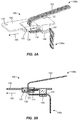
- an umbilical cable disconnect device 100 is illustrated in FIG. 1 .
- the system 101 can include an umbilical cable disconnect device 100, mounted about the side of a vehicle 103, and an umbilical cable 102, such that the disconnect device 100 is operable to disconnect the umbilical cable 102.
- the umbilical cable 102 can electrically couple the vehicle 103, such as a rocket, missile, warhead, or other kill vehicle, to a launch platform 104.
- an end of the umbilical cable 102 can be coupled to the vehicle 103 and an opposite end of the umbilical cable 102 can be coupled to the launch platform 104.
- the umbilical cable 102 can electrically couple the vehicle 103 to the launch platform 104 prior to launch of the vehicle 103 and the umbilical cable disconnect device 100 can disconnect the umbilical cable 102 upon launch of the vehicle 103 from the launch platform 104.
- the umbilical cable disconnect device 100 can be used, for example, to sever an umbilical cable for tube or rail launched rockets and missiles, incorporated in gravity/eject launched vehicles, or on a multi-staged vehicle for disconnecting an umbilical cable at stage separation.
- the umbilical cable disconnect device 100 can comprise a cutter 110 operable to cut the umbilical cable 102.
- the cutter 110 can comprise a non-metallic blade material to prevent a short circuit when cutting the umbilical cable 102.
- the cutter 110 can simultaneously contact two or more traces or wires within the umbilical cable, which can cause a short circuit.
- the likelihood of a short circuit of the umbilical cable 102 during severing or disconnect of the cable 102A can be prevented or minimized by utilizing a non-metallic blade material, such as a ceramic, an acrylic, or any other suitable non-metallic material.
- the cutter 110 can also include a straight-edge blade, a serrated-edge blade, or any other suitable blade type.
- the umbilical cable 102 can be configured to minimize trace overlap to prevent a short circuit upon disconnect of the umbilical cable 102.
- the traces of the cable 102 can locally "smear" or deform.
- smeared or deformed traces can contact one another after being cut, causing a short circuit.
- critical traces, or those traces that can cause a short circuit can be non-overlapping in the direction of the cut.
- Non-overlapping traces in the direction of the cut can minimize trace overlap or contact resulting from the cut and the local smearing or deformation of the traces, which can prevent the traces from causing a short circuit during or after severing or disconnect of the umbilical cable 102.
- the umbilical cable 102 can be configured as a ribbon cable having non-overlapping traces in the direction of cut (i.e., side by side) and the cutter 110 can be configured to cut roughly perpendicular to the width of the ribbon cable.
- the umbilical cable disconnect device 100 can be used to disconnect or sever any cable or trace configuration, such as a round cable, a flat cable, or any other cable configuration.
- an umbilical cable of any given shape can have any arrangement of traces configured to avoid smearing traces together, which could short circuit the umbilical cable.
- a spacer component 120 can be disposed between the cutter 110 and the umbilical cable 102.
- the spacer component 120 can maintain separation of the cutter 110 and the umbilical cable 102 prior to disconnect of the umbilical cable 102.
- the spacer component 120 can prevent the umbilical cable 102 from contacting the cutter 110 during normal handling and prior to launch of the vehicle 103.
- the spacer component 120 can be disposed about the cutter 110 and the umbilical cable 102 can extend through the spacer component 120.
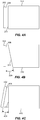
- the spacer component 120 can help maintain a desired orientation of the umbilical cable 102 relative to the cutter 110, such as a proper cutting angle or cut relationship, examples of which are shown in FIGS. 4A-4C .
- the orientation of the cutter 110 can be transverse to the portion of the umbilical cable 102 extending through the spacer component 120.
- the spacer component 120 can comprise an elastomeric material, such as rubber.
- the cutter 110 can be operable to penetrate the spacer component 120 in response to displacement of the cutter 110 (or the disconnect device 100) relative to the umbilical cable 102 in direction 105 to facilitate cutting of the umbilical cable 102 by the cutter 110 to disconnect the umbilical cable 102.
- displacement of the cutter 110 relative to the umbilical cable 102 can be caused by launching the vehicle 103 from the launch platform 104. Operation of the umbilical cable disconnect device 100 to disconnect the umbilical cable 102 can therefore be passive or responsive, and initiated by the launch of vehicle 103.
- FIGS. 3A-3D illustrate the umbilical cable disconnect device 100 in operation associated with the vehicle 103 and the launch platform 104.
- end 106a of the umbilical cable 102 can be coupled to the vehicle 103 and end 106b of the umbilical cable 102 can be coupled to the launch platform 104.
- the spacer component 120 can maintain separation of the cutter 110 and the umbilical cable 102 prior to initiation of the disconnect of the umbilical cable 102.
- the vehicle 103 can be configured to move in direction 105 when launched, such that tension is increased in the umbilical cable 102 as the vehicle 103 moves away from the launch platform 104.
- the cutter 110 can penetrate the spacer component 120.
- the spacer component 120 can also deform or compress in response to the cutter 110, as the cutter 110 moves closer to the umbilical cable 102.
- the cutter 110 can continue penetrating the spacer component 120 until reaching the umbilical cable 102, as shown in FIG. 3C , at which point the cutter 110 can cut the umbilical cable 102.
- FIG. 3D illustrates a completed cut and disconnect of the umbilical cable 102, with end 106a of the umbilical cable 102 remaining with the vehicle 103 and end 106b of the umbilical cable 102 remaining with the launch platform 104.
- the spacer component 120 can elastically return to its original form, pulling the remaining portion of the umbilical cable 102 that is within the spacer component 120 away from the cutter 110.
- the resulting configuration of the umbilical cable disconnect device 100 can provide a minimally intrusive aerodynamic form, with the severed portion of the umbilical cable 102 secured inside the vehicle 103 and presenting no aerodynamic concerns.
- the umbilical cable disconnect device 100 can also include a clamp 140 to facilitate fixing at least a portion 107 of the umbilical cable 102 relative to the umbilical cable disconnect device 100.
- the clamp 140 can secure the umbilical cable 102 such that tension in the umbilical cable 102 between the vehicle 103 and the launch platform 104 does not cause damage or other otherwise adversely affect the vehicle 103, such as by pulling on electronic components or connections.
- the clamp 140 can therefore isolate internal components and/or connections in the vehicle 103 from tension in the umbilical cable 102 between the vehicle 103 and the launch platform 104.
- the umbilical cable disconnect device 100 can include a base 130 having an opening 131 configured to receive the umbilical cable 102, such that the umbilical cable 102 extends through the base 130.
- the base 130 can be configured to be coupled to a body of the vehicle 103, such as with a fastener through one or more holes 132.
- the base 130 can serve as an access cover for the vehicle 103.
- the cutter 110 can extend into a periphery of the opening 131 of the base 130, which can facilitate contact between the cutter 110 and the umbilical cable 102 to disconnect the umbilical cable 102.
- the spacer component 120 can be molded around or otherwise disposed about the umbilical cable 102 and the cutter 110 to seal the opening 131 and, thus the body of the vehicle 103.
- the spacer component 120 can also be configured to resiliently flex to facilitate sealing of the opening 131 following disconnect of the umbilical cable 102.
- the spacer component 120 can be configured to provide an environmental seal of the opening 131 around the umbilical cable 102 and to maintain such a seal before and after disconnect of the umbilical cable 102.
- the base 130 can be operable to support the cutter 110, the spacer component 120, and/or the clamp 140. It should be recognized, however, that the cutter 110, the spacer component 120, and/or the clamp 140 can be supported by a structure independent from the base 120.
- the spacer component 120 can be configured to compress upon displacement of the cutter 110 or disconnect device 100 relative to the umbilical cable 102.
- tension in the umbilical cable 102 can increase, which can cause the umbilical cable 102 to compress the spacer component 120. This can allow the umbilical cable 102 to move toward the cutter 110 to facilitate severing and disconnect of the umbilical cable 102.
- the spacer component 120 can comprise a pre-formed piece, or a liquid material that sets up upon being disposed into the opening 131 of the base 130.
- the spacer component 120 can comprise a natural or a synthetic elastomeric material.
- the spacer component 120 material can be selected to effectively function as a seal in a desired temperature range, such that the spacer component can elastically deform to maintain the seal without being too stiff or too soft.
- FIGS. 4A-4C illustrate schematic examples of various cutter and umbilical cable configurations.
- FIG. 4A illustrates a cutter 210 having a blade edge 211 that is substantially parallel to a flat side 208 of an umbilical cable 202, which can be configured as a ribbon cable or other cable having a flat side.
- the entire side 208 of the umbilical cable 202 can contact the blade edge 211 of the cutter 210 at substantially the same time.
- FIG. 4B illustrates a cutter 310 having a blade edge 311 that is disposed at an angle 309 relative to a flat side 308 of an umbilical cable 302, which can be configured as a ribbon cable or other cable having a flat side.
- the blade edge 311 of the cutter 310 can progressively contact the side 308 of the umbilical cable 302 during the course of the cut, which can produce a lower cutting load on the umbilical cable 302 than in the example of FIG. 4A .
- the relative orientation of the cutter 210 and the umbilical cable 202 in FIG. 4A and the relative orientation of the cutter 310 and the umbilical cable 302 in FIG. 4B are substantially the same. The difference is the angle 309 built into the blade 311 of the cutter 310.
- FIG. 4C illustrates a cutter 410 having a blade edge 411 that can progressively contact the flat side 408 of an umbilical cable 402 during the course of the cut.
- relative orientation of the blade edge 411 and the umbilical cable 402 is such that the flat side 408 is disposed at an angle 409 relative to the blade edge 411.
- the separation component 120 can serve to maintain the umbilical cable 102 and the cutter 110 in a desired cutting orientation relative to one another. It should also be recognized that the cutter can be wider than the umbilical cable to ensure a complete cut of the cable.
- a method for facilitating disconnect of an umbilical cable can comprise obtaining an umbilical cable.
- the method can also comprise obtaining a cutter operable to cut the umbilical cable.
- the method can further comprise disposing a spacer component between the cutter and the umbilical cable, wherein and the spacer component maintains separation of the cutter and the umbilical cable prior to disconnect of the umbilical cable.
- the method can comprise facilitating displacement of the cutter relative to the umbilical cable, wherein the cutter is operable to penetrate the spacer component to facilitate cutting of the umbilical cable by the cutter to disconnect the umbilical cable. It is noted that no specific order is required in this method, though generally in one embodiment, these method steps can be carried out sequentially.
- the method can further comprise coupling an end of the umbilical cable to a vehicle and an opposite end of the umbilical cable to a launch platform.
- facilitating displacement of the cutter relative to the umbilical cable can comprise facilitating launch of the vehicle from the launch platform.
Landscapes
- Engineering & Computer Science (AREA)
- General Engineering & Computer Science (AREA)
- Electric Cable Installation (AREA)
Priority Applications (1)
| Application Number | Priority Date | Filing Date | Title |
|---|---|---|---|
| PL13843028T PL2920541T3 (pl) | 2012-11-13 | 2013-09-12 | Urządzenie odłączające przewód startowy |
Applications Claiming Priority (2)
| Application Number | Priority Date | Filing Date | Title |
|---|---|---|---|
| US13/675,925 US9074842B2 (en) | 2012-11-13 | 2012-11-13 | Umbilical cable disconnect |
| PCT/US2013/059521 WO2014120283A1 (en) | 2012-11-13 | 2013-09-12 | Umbilical cable disconnect |
Publications (2)
| Publication Number | Publication Date |
|---|---|
| EP2920541A1 EP2920541A1 (en) | 2015-09-23 |
| EP2920541B1 true EP2920541B1 (en) | 2018-05-30 |
Family
ID=50390174
Family Applications (1)
| Application Number | Title | Priority Date | Filing Date |
|---|---|---|---|
| EP13843028.5A Active EP2920541B1 (en) | 2012-11-13 | 2013-09-12 | Umbilical cable disconnect |
Country Status (4)
| Country | Link |
|---|---|
| US (1) | US9074842B2 (pl) |
| EP (1) | EP2920541B1 (pl) |
| PL (1) | PL2920541T3 (pl) |
| WO (1) | WO2014120283A1 (pl) |
Families Citing this family (5)
| Publication number | Priority date | Publication date | Assignee | Title |
|---|---|---|---|---|
| KR101894243B1 (ko) * | 2017-01-12 | 2018-09-04 | 국방과학연구소 | 유도로켓의 발사장치 |
| KR101824009B1 (ko) * | 2017-05-30 | 2018-01-31 | 국방과학연구소 | 유도탄 케이블 분리장치 |
| US11709035B2 (en) | 2021-08-12 | 2023-07-25 | Raytheon Company | Translating harness with passive disconnect |
| KR102799784B1 (ko) * | 2022-03-17 | 2025-04-25 | (주)이노스페이스 | 전자석을 이용한 우주발사체용 전기엄빌리컬시스템 |
| US12241718B2 (en) * | 2022-09-13 | 2025-03-04 | Raytheon Company | Passive line separator |
Family Cites Families (13)
| Publication number | Priority date | Publication date | Assignee | Title |
|---|---|---|---|---|
| US2870676A (en) | 1952-06-06 | 1959-01-27 | Radkowski Leo | Shearing device for cables |
| US3072021A (en) * | 1961-02-23 | 1963-01-08 | Lewis J Marcon | Missile umbilical assembly |
| US3122403A (en) * | 1961-12-18 | 1964-02-25 | Gen Dynamics Corp | Electrical disconnect |
| US3393605A (en) * | 1967-08-31 | 1968-07-23 | Paul E. Parnell | Explosively actuated device for high pressure environment |
| US3518613A (en) * | 1968-03-27 | 1970-06-30 | Us Navy | Missile umbilical cable |
| FR2132937A5 (pl) * | 1971-04-02 | 1972-11-24 | France Etat | |
| SE397407B (sv) * | 1975-02-19 | 1977-10-31 | Bofors Ab | Avrivningskontaktdon |
| US3991649A (en) * | 1975-06-27 | 1976-11-16 | Networks Electronic Corporation | Pyrotechnic wire cutter |
| DE3041149C2 (de) * | 1980-10-31 | 1986-10-02 | Dynamit Nobel Ag, 5210 Troisdorf | Verkabelung von Submunition |
| US6460445B1 (en) * | 2002-01-07 | 2002-10-08 | Eric P. Young | Playload dispensing system |
| US7026540B1 (en) * | 2005-04-04 | 2006-04-11 | The United States Of America As Represented By The Secretary Of The Navy | Tailcone assembly for a submarine countermeasure |
| US7575456B2 (en) * | 2006-11-29 | 2009-08-18 | Lockheed Martin Corporation | Retractable umbilical system and vehicle incorporating same |
| US8387501B2 (en) * | 2009-04-10 | 2013-03-05 | Bae Systems Information And Electronic Systems Integration Inc. | Method and apparatus for rapid severance of a decoy towline |
-
2012
- 2012-11-13 US US13/675,925 patent/US9074842B2/en active Active
-
2013
- 2013-09-12 WO PCT/US2013/059521 patent/WO2014120283A1/en not_active Ceased
- 2013-09-12 EP EP13843028.5A patent/EP2920541B1/en active Active
- 2013-09-12 PL PL13843028T patent/PL2920541T3/pl unknown
Non-Patent Citations (1)
| Title |
|---|
| None * |
Also Published As
| Publication number | Publication date |
|---|---|
| PL2920541T3 (pl) | 2018-09-28 |
| EP2920541A1 (en) | 2015-09-23 |
| US9074842B2 (en) | 2015-07-07 |
| WO2014120283A1 (en) | 2014-08-07 |
| US20150153135A1 (en) | 2015-06-04 |
Similar Documents
| Publication | Publication Date | Title |
|---|---|---|
| US9074842B2 (en) | Umbilical cable disconnect | |
| CN110168779B (zh) | 包括电极接片切断装置的袋形二次电池 | |
| US20210184379A1 (en) | FPCB Assembly for Battery Module, Its Manufacturing Method, and Battery Module Including the Same | |
| US8635937B2 (en) | Systems and methods for launching munitions | |
| US10700316B2 (en) | Battery housing, battery comprising a battery housing of this type, sheet element for producing a battery housing of this type, and method for producing a battery housing of this type | |
| WO2011068536A1 (en) | Free floating connector engagement and retention system and method | |
| EP2625749B1 (en) | A connector system | |
| CN104890902A (zh) | 一种熔断式压紧释放机构及其释放方法 | |
| US9546008B1 (en) | Miniature release mechanism or diminutive assembly for nanosatellite deployables (DANY) | |
| CN107871840A (zh) | 电池单元 | |
| US9038538B1 (en) | Initiator assembly with gas and/or fragment containment capabilities | |
| EP3246965B1 (en) | Battery cell assembly | |
| US12199392B2 (en) | Component pack of technical components, and technical component | |
| WO2014209470A2 (en) | Integrated antenna and antenna component | |
| US3140886A (en) | Coupling device | |
| EP3220484B1 (en) | Flex circuit connector configuration | |
| EP2763255B1 (en) | Connector comprising a plurality of terminals and a connector housing | |
| US8816711B2 (en) | Electrical probe assembly | |
| US12027282B2 (en) | Arrangement for attaching an insulator sleeve to an electrical conductor | |
| CN105217017A (zh) | 一种无人机机翼机械电气连接装置 | |
| EP2879198A1 (en) | Battery assembly internal connection device | |
| US8702448B2 (en) | Electrical connector | |
| US20180347942A1 (en) | Missile cable cutting system | |
| US3411401A (en) | Explosive driven guillotine | |
| EP4411965A1 (en) | Separation plate assembly, battery and electric device |
Legal Events
| Date | Code | Title | Description |
|---|---|---|---|
| PUAI | Public reference made under article 153(3) epc to a published international application that has entered the european phase |
Free format text: ORIGINAL CODE: 0009012 |
|
| 17P | Request for examination filed |
Effective date: 20150612 |
|
| AK | Designated contracting states |
Kind code of ref document: A1 Designated state(s): AL AT BE BG CH CY CZ DE DK EE ES FI FR GB GR HR HU IE IS IT LI LT LU LV MC MK MT NL NO PL PT RO RS SE SI SK SM TR |
|
| AX | Request for extension of the european patent |
Extension state: BA ME |
|
| DAX | Request for extension of the european patent (deleted) | ||
| GRAP | Despatch of communication of intention to grant a patent |
Free format text: ORIGINAL CODE: EPIDOSNIGR1 |
|
| INTG | Intention to grant announced |
Effective date: 20171122 |
|
| GRAJ | Information related to disapproval of communication of intention to grant by the applicant or resumption of examination proceedings by the epo deleted |
Free format text: ORIGINAL CODE: EPIDOSDIGR1 |
|
| GRAR | Information related to intention to grant a patent recorded |
Free format text: ORIGINAL CODE: EPIDOSNIGR71 |
|
| GRAS | Grant fee paid |
Free format text: ORIGINAL CODE: EPIDOSNIGR3 |
|
| GRAA | (expected) grant |
Free format text: ORIGINAL CODE: 0009210 |
|
| INTC | Intention to grant announced (deleted) | ||
| AK | Designated contracting states |
Kind code of ref document: B1 Designated state(s): AL AT BE BG CH CY CZ DE DK EE ES FI FR GB GR HR HU IE IS IT LI LT LU LV MC MK MT NL NO PL PT RO RS SE SI SK SM TR |
|
| INTG | Intention to grant announced |
Effective date: 20180420 |
|
| REG | Reference to a national code |
Ref country code: GB Ref legal event code: FG4D |
|
| REG | Reference to a national code |
Ref country code: CH Ref legal event code: EP |
|
| REG | Reference to a national code |
Ref country code: AT Ref legal event code: REF Ref document number: 1004056 Country of ref document: AT Kind code of ref document: T Effective date: 20180615 |
|
| REG | Reference to a national code |
Ref country code: IE Ref legal event code: FG4D |
|
| REG | Reference to a national code |
Ref country code: DE Ref legal event code: R096 Ref document number: 602013038368 Country of ref document: DE |
|
| REG | Reference to a national code |
Ref country code: FR Ref legal event code: PLFP Year of fee payment: 6 |
|
| REG | Reference to a national code |
Ref country code: NL Ref legal event code: MP Effective date: 20180530 |
|
| REG | Reference to a national code |
Ref country code: LT Ref legal event code: MG4D |
|
| PG25 | Lapsed in a contracting state [announced via postgrant information from national office to epo] |
Ref country code: SE Free format text: LAPSE BECAUSE OF FAILURE TO SUBMIT A TRANSLATION OF THE DESCRIPTION OR TO PAY THE FEE WITHIN THE PRESCRIBED TIME-LIMIT Effective date: 20180530 Ref country code: CY Free format text: LAPSE BECAUSE OF FAILURE TO SUBMIT A TRANSLATION OF THE DESCRIPTION OR TO PAY THE FEE WITHIN THE PRESCRIBED TIME-LIMIT Effective date: 20180530 Ref country code: LT Free format text: LAPSE BECAUSE OF FAILURE TO SUBMIT A TRANSLATION OF THE DESCRIPTION OR TO PAY THE FEE WITHIN THE PRESCRIBED TIME-LIMIT Effective date: 20180530 Ref country code: ES Free format text: LAPSE BECAUSE OF FAILURE TO SUBMIT A TRANSLATION OF THE DESCRIPTION OR TO PAY THE FEE WITHIN THE PRESCRIBED TIME-LIMIT Effective date: 20180530 Ref country code: BG Free format text: LAPSE BECAUSE OF FAILURE TO SUBMIT A TRANSLATION OF THE DESCRIPTION OR TO PAY THE FEE WITHIN THE PRESCRIBED TIME-LIMIT Effective date: 20180830 Ref country code: FI Free format text: LAPSE BECAUSE OF FAILURE TO SUBMIT A TRANSLATION OF THE DESCRIPTION OR TO PAY THE FEE WITHIN THE PRESCRIBED TIME-LIMIT Effective date: 20180530 Ref country code: NO Free format text: LAPSE BECAUSE OF FAILURE TO SUBMIT A TRANSLATION OF THE DESCRIPTION OR TO PAY THE FEE WITHIN THE PRESCRIBED TIME-LIMIT Effective date: 20180830 |
|
| PG25 | Lapsed in a contracting state [announced via postgrant information from national office to epo] |
Ref country code: GR Free format text: LAPSE BECAUSE OF FAILURE TO SUBMIT A TRANSLATION OF THE DESCRIPTION OR TO PAY THE FEE WITHIN THE PRESCRIBED TIME-LIMIT Effective date: 20180831 Ref country code: RS Free format text: LAPSE BECAUSE OF FAILURE TO SUBMIT A TRANSLATION OF THE DESCRIPTION OR TO PAY THE FEE WITHIN THE PRESCRIBED TIME-LIMIT Effective date: 20180530 Ref country code: LV Free format text: LAPSE BECAUSE OF FAILURE TO SUBMIT A TRANSLATION OF THE DESCRIPTION OR TO PAY THE FEE WITHIN THE PRESCRIBED TIME-LIMIT Effective date: 20180530 Ref country code: HR Free format text: LAPSE BECAUSE OF FAILURE TO SUBMIT A TRANSLATION OF THE DESCRIPTION OR TO PAY THE FEE WITHIN THE PRESCRIBED TIME-LIMIT Effective date: 20180530 |
|
| REG | Reference to a national code |
Ref country code: AT Ref legal event code: MK05 Ref document number: 1004056 Country of ref document: AT Kind code of ref document: T Effective date: 20180530 |
|
| PG25 | Lapsed in a contracting state [announced via postgrant information from national office to epo] |
Ref country code: NL Free format text: LAPSE BECAUSE OF FAILURE TO SUBMIT A TRANSLATION OF THE DESCRIPTION OR TO PAY THE FEE WITHIN THE PRESCRIBED TIME-LIMIT Effective date: 20180530 |
|
| PG25 | Lapsed in a contracting state [announced via postgrant information from national office to epo] |
Ref country code: CZ Free format text: LAPSE BECAUSE OF FAILURE TO SUBMIT A TRANSLATION OF THE DESCRIPTION OR TO PAY THE FEE WITHIN THE PRESCRIBED TIME-LIMIT Effective date: 20180530 Ref country code: SK Free format text: LAPSE BECAUSE OF FAILURE TO SUBMIT A TRANSLATION OF THE DESCRIPTION OR TO PAY THE FEE WITHIN THE PRESCRIBED TIME-LIMIT Effective date: 20180530 Ref country code: AT Free format text: LAPSE BECAUSE OF FAILURE TO SUBMIT A TRANSLATION OF THE DESCRIPTION OR TO PAY THE FEE WITHIN THE PRESCRIBED TIME-LIMIT Effective date: 20180530 Ref country code: RO Free format text: LAPSE BECAUSE OF FAILURE TO SUBMIT A TRANSLATION OF THE DESCRIPTION OR TO PAY THE FEE WITHIN THE PRESCRIBED TIME-LIMIT Effective date: 20180530 Ref country code: DK Free format text: LAPSE BECAUSE OF FAILURE TO SUBMIT A TRANSLATION OF THE DESCRIPTION OR TO PAY THE FEE WITHIN THE PRESCRIBED TIME-LIMIT Effective date: 20180530 Ref country code: EE Free format text: LAPSE BECAUSE OF FAILURE TO SUBMIT A TRANSLATION OF THE DESCRIPTION OR TO PAY THE FEE WITHIN THE PRESCRIBED TIME-LIMIT Effective date: 20180530 |
|
| PG25 | Lapsed in a contracting state [announced via postgrant information from national office to epo] |
Ref country code: SM Free format text: LAPSE BECAUSE OF FAILURE TO SUBMIT A TRANSLATION OF THE DESCRIPTION OR TO PAY THE FEE WITHIN THE PRESCRIBED TIME-LIMIT Effective date: 20180530 Ref country code: IT Free format text: LAPSE BECAUSE OF FAILURE TO SUBMIT A TRANSLATION OF THE DESCRIPTION OR TO PAY THE FEE WITHIN THE PRESCRIBED TIME-LIMIT Effective date: 20180530 |
|
| REG | Reference to a national code |
Ref country code: DE Ref legal event code: R097 Ref document number: 602013038368 Country of ref document: DE |
|
| PLBE | No opposition filed within time limit |
Free format text: ORIGINAL CODE: 0009261 |
|
| STAA | Information on the status of an ep patent application or granted ep patent |
Free format text: STATUS: NO OPPOSITION FILED WITHIN TIME LIMIT |
|
| PG25 | Lapsed in a contracting state [announced via postgrant information from national office to epo] |
Ref country code: MC Free format text: LAPSE BECAUSE OF FAILURE TO SUBMIT A TRANSLATION OF THE DESCRIPTION OR TO PAY THE FEE WITHIN THE PRESCRIBED TIME-LIMIT Effective date: 20180530 |
|
| REG | Reference to a national code |
Ref country code: CH Ref legal event code: PL |
|
| 26N | No opposition filed |
Effective date: 20190301 |
|
| PG25 | Lapsed in a contracting state [announced via postgrant information from national office to epo] |
Ref country code: SI Free format text: LAPSE BECAUSE OF FAILURE TO SUBMIT A TRANSLATION OF THE DESCRIPTION OR TO PAY THE FEE WITHIN THE PRESCRIBED TIME-LIMIT Effective date: 20180530 |
|
| REG | Reference to a national code |
Ref country code: BE Ref legal event code: MM Effective date: 20180930 |
|
| REG | Reference to a national code |
Ref country code: IE Ref legal event code: MM4A |
|
| PG25 | Lapsed in a contracting state [announced via postgrant information from national office to epo] |
Ref country code: LU Free format text: LAPSE BECAUSE OF NON-PAYMENT OF DUE FEES Effective date: 20180912 |
|
| PG25 | Lapsed in a contracting state [announced via postgrant information from national office to epo] |
Ref country code: IE Free format text: LAPSE BECAUSE OF NON-PAYMENT OF DUE FEES Effective date: 20180912 |
|
| PG25 | Lapsed in a contracting state [announced via postgrant information from national office to epo] |
Ref country code: LI Free format text: LAPSE BECAUSE OF NON-PAYMENT OF DUE FEES Effective date: 20180930 Ref country code: BE Free format text: LAPSE BECAUSE OF NON-PAYMENT OF DUE FEES Effective date: 20180930 Ref country code: CH Free format text: LAPSE BECAUSE OF NON-PAYMENT OF DUE FEES Effective date: 20180930 |
|
| PG25 | Lapsed in a contracting state [announced via postgrant information from national office to epo] |
Ref country code: AL Free format text: LAPSE BECAUSE OF FAILURE TO SUBMIT A TRANSLATION OF THE DESCRIPTION OR TO PAY THE FEE WITHIN THE PRESCRIBED TIME-LIMIT Effective date: 20180530 |
|
| PG25 | Lapsed in a contracting state [announced via postgrant information from national office to epo] |
Ref country code: MT Free format text: LAPSE BECAUSE OF NON-PAYMENT OF DUE FEES Effective date: 20180912 |
|
| PG25 | Lapsed in a contracting state [announced via postgrant information from national office to epo] |
Ref country code: TR Free format text: LAPSE BECAUSE OF FAILURE TO SUBMIT A TRANSLATION OF THE DESCRIPTION OR TO PAY THE FEE WITHIN THE PRESCRIBED TIME-LIMIT Effective date: 20180530 |
|
| PG25 | Lapsed in a contracting state [announced via postgrant information from national office to epo] |
Ref country code: PT Free format text: LAPSE BECAUSE OF FAILURE TO SUBMIT A TRANSLATION OF THE DESCRIPTION OR TO PAY THE FEE WITHIN THE PRESCRIBED TIME-LIMIT Effective date: 20180530 |
|
| PG25 | Lapsed in a contracting state [announced via postgrant information from national office to epo] |
Ref country code: MK Free format text: LAPSE BECAUSE OF NON-PAYMENT OF DUE FEES Effective date: 20180530 Ref country code: HU Free format text: LAPSE BECAUSE OF FAILURE TO SUBMIT A TRANSLATION OF THE DESCRIPTION OR TO PAY THE FEE WITHIN THE PRESCRIBED TIME-LIMIT; INVALID AB INITIO Effective date: 20130912 |
|
| PG25 | Lapsed in a contracting state [announced via postgrant information from national office to epo] |
Ref country code: IS Free format text: LAPSE BECAUSE OF FAILURE TO SUBMIT A TRANSLATION OF THE DESCRIPTION OR TO PAY THE FEE WITHIN THE PRESCRIBED TIME-LIMIT Effective date: 20180930 |
|
| P01 | Opt-out of the competence of the unified patent court (upc) registered |
Effective date: 20230530 |
|
| PGFP | Annual fee paid to national office [announced via postgrant information from national office to epo] |
Ref country code: DE Payment date: 20250820 Year of fee payment: 13 |
|
| PGFP | Annual fee paid to national office [announced via postgrant information from national office to epo] |
Ref country code: PL Payment date: 20250825 Year of fee payment: 13 |
|
| PGFP | Annual fee paid to national office [announced via postgrant information from national office to epo] |
Ref country code: GB Payment date: 20250822 Year of fee payment: 13 |
|
| PGFP | Annual fee paid to national office [announced via postgrant information from national office to epo] |
Ref country code: FR Payment date: 20250820 Year of fee payment: 13 |