EP2919610B1 - Schuhoberteil mit mehreren ungeschweissten flexiblen zonen - Google Patents
Schuhoberteil mit mehreren ungeschweissten flexiblen zonen Download PDFInfo
- Publication number
- EP2919610B1 EP2919610B1 EP14712063.8A EP14712063A EP2919610B1 EP 2919610 B1 EP2919610 B1 EP 2919610B1 EP 14712063 A EP14712063 A EP 14712063A EP 2919610 B1 EP2919610 B1 EP 2919610B1
- Authority
- EP
- European Patent Office
- Prior art keywords
- zone
- shoe
- weld
- weld zone
- unwelded
- Prior art date
- Legal status (The legal status is an assumption and is not a legal conclusion. Google has not performed a legal analysis and makes no representation as to the accuracy of the status listed.)
- Active
Links
Images






Classifications
-
- A—HUMAN NECESSITIES
- A43—FOOTWEAR
- A43B—CHARACTERISTIC FEATURES OF FOOTWEAR; PARTS OF FOOTWEAR
- A43B23/00—Uppers; Boot legs; Stiffeners; Other single parts of footwear
- A43B23/02—Uppers; Boot legs
- A43B23/0245—Uppers; Boot legs characterised by the constructive form
-
- A—HUMAN NECESSITIES
- A43—FOOTWEAR
- A43B—CHARACTERISTIC FEATURES OF FOOTWEAR; PARTS OF FOOTWEAR
- A43B23/00—Uppers; Boot legs; Stiffeners; Other single parts of footwear
- A43B23/02—Uppers; Boot legs
- A43B23/0205—Uppers; Boot legs characterised by the material
- A43B23/0235—Different layers of different material
-
- A—HUMAN NECESSITIES
- A43—FOOTWEAR
- A43B—CHARACTERISTIC FEATURES OF FOOTWEAR; PARTS OF FOOTWEAR
- A43B23/00—Uppers; Boot legs; Stiffeners; Other single parts of footwear
- A43B23/02—Uppers; Boot legs
- A43B23/0245—Uppers; Boot legs characterised by the constructive form
- A43B23/0255—Uppers; Boot legs characterised by the constructive form assembled by gluing or thermo bonding
-
- A—HUMAN NECESSITIES
- A43—FOOTWEAR
- A43B—CHARACTERISTIC FEATURES OF FOOTWEAR; PARTS OF FOOTWEAR
- A43B23/00—Uppers; Boot legs; Stiffeners; Other single parts of footwear
- A43B23/02—Uppers; Boot legs
- A43B23/0245—Uppers; Boot legs characterised by the constructive form
- A43B23/0265—Uppers; Boot legs characterised by the constructive form having different properties in different directions
- A43B23/0275—Uppers; Boot legs characterised by the constructive form having different properties in different directions with a part of the upper particularly rigid, e.g. resisting articulation or torsion
Definitions
- Articles of footwear generally include two primary elements: an upper and a sole structure.
- the upper is often formed from a plurality of material elements (e.g., textiles, polymer sheet layers, foam layers, leather, synthetic leather) that are stitched or adhesively bonded together to form a void on the interior of the footwear for comfortably and securely receiving a foot. More particularly, the upper forms a structure that extends over instep and toe areas of the foot, along medial and lateral sides of the foot, and around a heel area of the foot.
- the upper may also incorporate a lacing system to adjust fit of the footwear, as well as permitting entry and removal of the foot from the void within the upper.
- the upper may include a tongue that extends under the lacing system to enhance adjustability and comfort of the footwear, and the upper may incorporate a heel counter.
- textile elements may provide breathability and may absorb moisture from the foot, foam layers may compress to impart comfort, and leather may impart durability and wear-resistance. Further over lapping pieces of material may impart stability and structure to specific parts of the shoe.
- the overall mass of the footwear may increase proportionally.
- the time and expense associated with transporting, stocking, cutting, and joining the material elements may also increase.
- waste material from cutting and stitching processes may accumulate to a greater degree as the number of material elements incorporated into an upper increases.
- products with a greater number of material elements may be more difficult to recycle than products formed from fewer material elements.
- the sole structure is secured to a lower portion of the upper so as to be positioned between the foot and the ground.
- the sole structure includes a midsole and an outsole.
- the midsole may be formed from a polymer foam material that attenuates ground reaction forces (i.e., provides cushioning) during walking, running, and other ambulatory activities.
- the midsole may also include fluid-filled chambers, plates, moderators, or other elements that further attenuate forces, enhance stability, or influence the motions of the foot, for example.
- the outsole forms a ground-contacting element of the footwear and is usually fashioned from a durable and wear-resistant rubber material that includes texturing to impart traction.
- the sole structure may also include a sockliner positioned within the upper and proximal a lower surface of the foot to enhance footwear comfort.
- US 2010/037483 A1 discloses an article of footwear having a sole structure and an upper that includes a foundation element and a tensile element.
- the present disclosure relates generally to a shoe upper having multiple welds in selected locations on the shoe upper.
- the welded sections may provide structure and stability to the selected locations.
- the shoe upper may include at least one zone without welds.
- the disclosure provides a shoe upper according to claim 1 and a shoe according to appended claim 8.
- Preferred embodiments are defined in the dependent claims.
- the shoe upper of this disclosure may be configured for use in a wide range of athletic footwear styles, including running shoes, basketball shoes, cross-training shoes, football shoes, golf shoes, hiking shoes and boots, ski and snowboarding boots, soccer shoes, tennis shoes, and walking shoes, for example.
- Concepts associated with the shoe upper having multiple welds in selected areas may also be utilized with footwear styles that are generally considered to be primarily nonathletic, including dress shoes, loafers, sandals, casual shoes, clogs, flats, heels, pumps, wedges, and work boots.
- welding material to provide support and structure as well as to form unwelded flex zones may be incorporated into other types of apparel and athletic equipment, including helmets, gloves, and protective padding for sports, such as football and hockey. Similar material may also be incorporated into cushions and other compressible structures utilized in household goods and industrial products.
- shoe upper and “upper” may be used interchangeably.
- the shoe upper or upper may include all portions of the shoe, excluding the laces and the sole structure.
- FIG. 1 depicts an embodiment of the lateral side of shoe 100 having an upper 114 having multiple welds, such as first weld 121 and second weld 123.
- the multiple welds may be located in specific portions of upper 114.
- the upper may include multiple locations or zones having multiple welds.
- upper 114 may include multiple zones that remain unwelded.
- portions of the shoe upper may be fused or welded.
- the individual fibers, filaments, strands or layers that compose the base material of the upper may be fused or welded.
- upper 114 may include base material 112.
- Base material may include one or more welds, such as first weld 121 and second weld 123.
- welds formed in the upper are depicted as solid lines.
- the base material of the upper may be formed from any suitable material for a shoe upper.
- the base materials may be a woven or non-woven material.
- the base material may be suitable for the fusing method utilized to form the welds in the base material.
- the base material may be a single layer of material. In other embodiments, the base material may be two or more layers. When the base material is multiple layers, each layer may be made of the same material or combination of materials. In other embodiments, each layer of the base material may be made of different suitable materials or combination of materials. Again, the materials used for the one or more layers of the base material of the upper may be suitable for the fusion method chosen to form the welds in the base material.
- base material 112 may be a single layer.
- the welds include areas in which the individual fibers, filaments or strands of the layer of base material 112 are fused or melted together.
- base material 112 of upper 114 may include two or more layers.
- the welds may include fusing one layer to other layer.
- the top layer may only be welded, similar to a single layer base material, where the fibers, filaments or strands of the layer are fused. In multi-layer base material, the welds may appear indented into the material.
- the welds of the upper may be formed by any suitable method of fusing materials of a shoe upper.
- the base material of the upper may be fused by a thermal fusion method.
- the thermal fusion method may include bonding through hot die, steam or hot air heating methods.
- the base material of the upper may be fused by a welding method.
- welding methods may be utilized to form welds in a shoe upper.
- the welding method utilized to create the welds may include a high frequency welding method.
- the high frequency welding method may include an ultrasonic welding method or a radio frequency welding method.
- the base material may be made of any material suitable for such a method. Further, the base material may be made of any material suitable for high frequency welding methods.
- Materials suitable for high frequency welding include thermoplastic material or natural material coated with a thermoplastic material. Examples of material suitable for high frequency welding methods include an acrylic, a nylon, a polyester, a polylactic acid, a polyethylene, a polypropylene, polyvinyl chloride (PVC), an urethane, a natural fiber, such as cotton or wool, that is coated with one or more thermoplastic materials, such as an ethyl vinyl acetate or thermoplastic polyurethane, and combinations thereof.
- an ultrasonic welding device is used to fuse portions of the base material.
- Ultrasonic welding devices utilize high frequency ultrasonic acoustic vibrations. The vibrations may be applied locally to a portion of the base material of the shoe upper. Further, the vibrations applied to the base material cause friction. The friction softens the base material to fuse the specific portion of the material. The fusion of the selected portions of the upper may be considered a solid state weld.
- Some embodiments may employ one or more of the principles, concepts or methods disclosed in the following: Albanese et al., U.S. Patent Number 7,883,594 , entitled “Wrapped pile weatherstripping and methods of making same,” issued on February 8, 2011; Chernyak, U.S. Patent Number 7,824,513 , entitled “Apparatus and method for making pile articles and improved pile articles made therewith,” issued on November 2, 2010; Lehto et al., U.S. Patent Number 7,776,171 , entitled “Arrangement and method for treatment of a material by means of an ultrasonic device,” issued on August 17, 2010; Perrine, U.S.
- Patent Number 6,835,257 entitled “Ultrasonic weld pattern for adsorbent containing package” issued on December 28, 2004; and Collette et al., U.S. Patent Number 5,713,399 , entitled “Ultrasonic seaming of abutting strips for paper machine clothing” issued on February 3,1998.
- the lateral side of shoe upper 114 may have multiple weld zones and multiple zones that are unwelded.
- First weld zone 120 may be located in toe box portion of the shoe.
- Second weld zone 124 may be located along the lateral side between the first eyelet portion 154 and sole structure 140.
- Third weld zone 128 may be located along the lateral side between the second eyelet portion 152 and the sole structure 140.
- Fourth weld zone 132 may be located from the third eyelet portion 150 around the ankle portion of upper 114 to outer heel support 142.
- upper 114 may include unwelded flex zones on the lateral side of the shoe.
- First unwelded flex zone 122 may be located in the toe box portion of upper 114 between first weld zone 120 and second weld zone 124.
- First unwelded flex zone may span radially from sole structure 140 on the lateral side of upper 114 to toe strap 144 on the medial side of upper 114.
- First unwelded flex zone 122 may be configured to flex similarly to the flex that takes place between the toes and instep when the foot is flexed.
- Second unwelded flex zone 126 may be located between second weld zone 124 and third weld zone 128. In addition, second unwelded flex zone 126 may continue between first eyelet portion 154 and second eyelet portion 152. Second unwelded flex zone 126 may be configured to flex when the foot flexes between the toes and instep. Further, second unwelded flex zone 126 may be configured to flex when the foot flexes between the instep and the ankle.
- Third unwelded flex zone 130 may be located between third weld zone 128 and fourth weld zone 132. Like second unwelded flex zone126, third unwelded flex zone 132 may continue between second eyelet portion 152 and third eyelet portion 150. Third unwelded flex zone 130 may be configured to flex when the foot flexes between the instep and the ankle.
- shoe upper 114 may also include additional materials.
- the additional materials may be overlaid on base material 112 of upper 114.
- upper 114 of shoe 100 may include toe cap 110.
- Toe cap 110 may be formed from additional material.
- the additional material may be overlaid on base material 112.
- Toe cap 110 may span from the medial side to the lateral side of upper 114 in the toe box portion of the upper.
- the additional materials may include any suitable material for a shoe upper.
- the suitable material may include woven textiles, nonwoven textiles, polymer sheet layers, plastics, rubbers, foam layers, leather, and synthetic leather.
- the additional materials may include the same materials recited above as suitable for the base material.
- the base material and the additional material may be different. In other embodiments, the base material and additional material may be the same.
- Upper 114 of shoe 100 may further include heel support 142.
- Heel support 142 may be formed from additional material. The additional material may be overlaid on base material 112 of the upper. Heel support 142 may span from the medial side to the lateral side of upper 114 wrapping around the heel portion of the upper. Further, heel support 142 may be in contact with sole structure 140.
- Each weld zone may include any number of welds.
- the number of welds in each weld zone may depend on the amount of support and structure the desired for that particular zone.
- the welds may be formed in each weld zone in any suitable pattern. In some cases, the amount of support and structure desired for each zone may determine the number of welds as well as the pattern of welds.
- the weld or welds described above may be used to vary one or more properties of the upper.
- the weld or welds may provide a base material that stretches less in any direction in that specific location.
- the weld or welds formed in the base material may restrain the base material from stretching in a lateral direction.
- the weld or welds formed in the base material may restrain the base material from stretching in a longitudinal direction.
- the weld or welds formed in the base material may restrain the base material from stretching in both a lateral and longitudinal direction.
- the weld or welds formed in the base material provide similar support and structure to an upper that the inclusion of additional material in those same areas would if the additional material had been applied.
- the weld or welds may also be used to reduce bending of the base material.
- the weld or welds may increase the strength of the base material.
- the weld or welds may increase the rigidity of the base material of the upper. Further, the weld or welds may reduce the flexibility of the base material of the upper in the weld zones.
- the unwelded flex zones of the upper may not restrain the base material from stretching or flexing.
- the unwelded flex zones are left unwelded in selected locations on the upper.
- the locations may be areas the shoe flexes during use.
- the upper of the shoe may flex in the same location and manner that the foot inside the shoe flexes. Therefore, the shoe upper of this disclosure not only may include welds formed in selected locations impart support and structure in those locations, but the shoe upper may include unwelded areas that also may be selectively located on the upper.
- a foot within the shoes described above may tend to stretch the upper component of the shoe. That is, many of the material elements forming the upper (e.g., base material of the upper) may stretch when placed in tension by movements of the foot. Although the welds of the upper may also stretch, the welds generally stretch to a lesser degree than the other material elements forming the upper.
- the various welds of the upper may be located on the upper, therefore, to form structural components in the upper that (a) resist stretching in specific directions or locations, (b) limit excess movement of the foot relative to the sole structure and the upper, (c) ensure that the foot remains properly positioned relative to the sole structure and the upper, and/or (d) reinforce locations where forces are concentrated.
- the unwelded flex zones may be located on the upper to ensure that the upper of the shoe flexes in a substantially similar manner that the foot inside the shoe flexes.
- first weld zone 120 of the toe box portion of the upper or third weld zone 128 may be desirable to have first weld zone 120 of the toe box portion of the upper or third weld zone 128 remain flexible in certain directions.
- First weld zone 120 and third weld zone 128 may be selected to remain flexible in the longitudinal direction (heel to toe direction) but less flexible in the lateral direction (instep to sole direction).
- Each weld zone may include provisions for reducing the stretching of the base material. Further, each zone may include provisions for reducing the bending of the base material. In some embodiments, each zone may include provisions for increasing the strength of the base material. Still further, each zone may include provisions for increasing the rigidity of the base material of the upper. In other embodiments, each zone may include provisions for reducing the flexibility of the base material of the upper.
- the welds of each weld zone may be oriented in any direction.
- the welds may be located on the upper in a longitudinal, or lengthwise, direction.
- the welds of a weld zone may be located in a lateral, or widthwise, direction.
- the welds of a weld zone may be located in a diagonal direction, which is a direction between the longitudinal and lateral directions.
- the welds of a particular weld zone may not intersect. Further, the welds of a particular weld zone may be in the same direction. In other embodiments, two or more welds of a weld zone may intersect. Further, the welds of a weld zone may intersect more than one other weld. In some weld zones, some welds intersect while others do not. The degree of intersection may determine how much the stretch, bending, or flexibility of the material is reduced, and how much the strength and rigidity is increased.
- the welds may be located on the upper in any direction.
- the welds themselves may be formed in any shape.
- the shape of the weld may be a solid line.
- the shape of the weld may be a broken or dashed line.
- the shape of the weld may be a wavy line.
- the shape of the weld may be a zigzag pattern.
- each weld of a weld zone may have a different weld pattern. Further still, each weld zone may include a different set of weld patterns.
- third weld zone 128 may also include a series of welds that are located in substantially the same direction. In third weld zone 128, the welds may be located from second eyelet portion 152 to sole structure 140.
- the second weld zone 124 between first eyelet portion 154 and sole structure 140 as well as fourth weld zone 132 in the ankle portion of the upper may be selected as an area that needs additional support.
- weld zones in which additional support is needed such as second weld zone 124, may be selected to be less flexible. Further, such weld zones may be less stretchable. Still further, weld zones having added support may be less bendable.
- such weld zone may be stronger and/or more rigid in multiple directions. In order to achieve one or more of those characteristics, multiple welds may be formed in this zone. Further, the welds may be formed in multiple directions. In addition, some of the welds may intersect.
- the welds of second weld zone 124 and fourth weld zone 132 may not be formed in the same general direction.
- the welds of each zone may be formed in multiple directions. Further, the welds of each zone may intersect. The intersections may restrain the flexibility, stretch and/or bend of each zone in multiple directions. Further, the weld intersection may further increase the strength and rigidity of the weld zone.
- the flexibility of second weld zone 124 and fourth weld zone 132 may be restricted in both the lateral and longitudinal directions. Again, the number of welds and the pattern of welds may depend on the degree of support and structure needed in each weld zone.
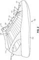
- FIG. 2 depicts an embodiment of the medial side of shoe 100. Similar to the lateral side of upper 114 shown in FIG. 1 , the medial side of upper 114 may have multiple weld zones. Further, the medial side also may include unwelded zones. Unlike the lateral side of upper 114, the medial side of upper 114 also includes additional material is certain locations.
- the medial side of upper 114 may include additional material in selected areas.
- additional material is added as toe strap 144.
- Toe strap 144 is an additional piece of material that may be located over or on top of the upper base material. This additional material may provide support and stability this selected area. Toe strap 144 may provide additional forefoot support when a person wearing shoe 100 moves or cuts.
- the medial side of upper 114 includes multiple weld zones.
- Fifth weld zone 160 is located adjacent to toe strap 144.
- Fifth weld zone 160 is located between the fourth eyelet portion 172 and sole structure 140.
- fifth weld zone 160 may include multiple welds.
- the welds of fifth weld zone 160 may be formed in multiple directions.
- the welds of fifth weld zone 160 may intersect.
- the medial side of upper 114 may include sixth weld zone 164. Similar to third weld zone 128, sixth weld zone 164 may remain flexible in certain directions. Sixth weld zone 164 may be selected to remain flexible in the longitudinal direction but less flexible in the lateral direction. In such a case, sixth weld zone 164 may include a series of welds that generally may be in the same direction. More specifically, in sixth weld zone 164, the welds are formed from fifth eyelet portion 174 to sole structure 140.
- the medial side of the embodiment shown in FIG. 2 also may include seventh weld zone 178.
- Seventh weld zone 178 may be similar to fourth weld zone 132 shown in FIG. 1 .
- the welds of seventh weld zone 178 may not be formed in the same general direction.
- the welds of seventh weld zone 178 may be formed in multiple directions.
- the welds of seventh weld zone 178 may intersect. The intersections may restrain the flexibility or stretchability of the weld zone in multiple directions.
- the flexibility or stretchability of seventh weld zone 178 may be restrained in both the lateral and longitudinal directions.
- the number of welds and the pattern of welds in seventh weld zone 178 may depend on the degree of support and structure needed in each weld zone.
- the medial side of upper 114 also may include unwelded flex zones.
- Fourth unwelded flex zone 162 may be located between fifth weld zone 160 and sixth weld zone 164.
- fourth unwelded flex zone 162 may continue between fourth eyelet portion 172 and fifth eyelet portion 174.
- Fourth unwelded flex zone 162 may be configured to flex when the foot flexes between the toes and instep. Further, fourth unwelded flex zone 162 may flex when the foot flexes between the instep and the ankle.
- Fifth unwelded flex zone 166 may be located between second weld zone 164 and ankle strap 170. Fifth unwelded flex zone 166 may continue between fifth eyelet portion 174 and sixth eyelet portion 176. Fifth unwelded flex zone 164 may be configured to flex when the foot flexes between the instep and the ankle.
- the number of welds and the pattern of welds may depend on the degree of support and structure needed in each weld zone.
- the number of weld zones on the medial side of upper 114 may be the same as the number of weld zones on the lateral side of upper 114.
- the number of weld zones on the medial side of upper 114 may be different than the number of weld zones on the lateral side of upper 114.
- each weld zone may include a different or unique weld pattern when compared the other weld zones of upper 114.
- FIG. 3 depicts a top view of an embodiment of the toe portion and instep portion of shoe 100.
- FIG. 3 shows the multiple weld zones and unwelded zones of shoe 100 on both the medial side and the lateral side of the shoe.
- toe strap 144 is shown on the medial side of upper 114. Toe strap 144 may span from sole structure 140 to fourth eyelet portion 172. Toe strap 144 may be affixed to the base material of the upper of shoe 100. In some embodiments, toe strap 144 may be affixed to the base material with stitching or an adhesive material. Toe strap 144 may help the foot to remain in the proper location within shoe 100 while a wearer is moving.
- the lateral side of shoe 100 lacks additional material in the approximately the same area. However, the lateral side of shoe 100 has second weld zone 124.
- second weld zone 124 may include multiple welds. The welds of second weld zone 124 may also intersect. The series of welds in second weld zone 124 may provide the necessary support for this portion of upper 114. Second weld zone 124 may provide support for the wearer of shoe 100 in order for the wearer's foot to remain in the proper location within the shoe. In other words, second weld zone 124 may perform the same function on the lateral side of shoe 100 as toe strap 144 performs on the medial side of shoe 100. In some cases, second weld zone 124 may be characterized as an extension of toe strap 144. Forming a weld zone in place of a second toe strap on the lateral side of the shoe may lighten the shoe, decrease the cost of the shoe's materials, and reduce the complexity of the manufacturing process.
- top view of FIG. 3 illustrates lateral side of upper 114 and medial side of upper 114 may have corresponding welded and unwelded zones. More specifically, as can be seen in FIG. 3 , second unwelded flex zone 126 on the lateral side of shoe 100 may correspond to fourth unwelded flex zone162 on the medial side of shoe 100.
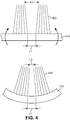
- FIG. 4 is a schematic diagram of the concept of positional relationships of items attached to a rigid member as it flexes. This concept may be applied to the welds and weld zones of a shoe upper (the items) and sole structure (rigid member), which is discussed in further detail below.
- the lines or items 420 in two zones may be fixed to rigid member 410.
- the zones containing items 420 may be spaced a certain distance apart, L1, where the zones contact the rigid member. Further, at rest, the zones may be a second distance apart from each other (L2) at a specific distance away from the rigid member.
- FIG. 5 depicts the embodiment of a shoe as shown in FIG. 1 as it flexes during use.
- the concept depicted in the illustrations of FIG. 4 above may be applied to a shoe in use as it flexes.
- the portions of shoe 100 including portions of upper 114 and sole structure 140, may flex.
- second flex zone 126 and third flex zone 130 may flex.
- the weld zones bordering each flex zone move closer together. This is shown in greater detail below in FIGS. 10, 11 , 14 and 15 .
- FIG. 6 depicts a schematic of another embodiment of the lateral side of shoe 200.
- the embodiment shown in FIG. 6 is similar to the embodiment shown in FIG. 1 .
- the embodiment shown in FIG. 6 may not include extra material on shoe upper 114, such as the eyelet portions.
- shoe upper 114 may include primarily the base material and a series of selective welds.
- FIG. 6 depicts an embodiment of the lateral side of shoe 200 having an upper having multiple welds.
- the multiple welds may be located in specific portions of upper 114.
- upper 114 may include multiple locations or zones having multiple welds. Further, upper 114 may include multiple zones that remain unwelded.
- the lateral side of upper 114 may have multiple weld zones and multiple zones that are unwelded.
- First weld zone 120 may be located in the toe box portion of shoe 200.
- Second weld zone 124 may be located along the lateral side between first eyelet 310 and second eyelet 312 and sole structure 140.
- Third weld zone 128 may be located along the lateral side between the third eyelet 314, fourth eyelet 316, and fifth eyelet 318, and the sole structure 140.
- Fourth weld zone 132 may be located from the sixth eyelet 320 and seventh eyelet 322, around the ankle portion of upper 114 to outer heel support 142.
- upper 114 may include unwelded flex zones on the lateral side of shoe 200.
- First unwelded flex zone 122 may be located in the toe box portion of upper 114 between first weld zone 120 and second weld zone 124.
- First unwelded flex zone may span radially from sole structure 140 on the lateral side of upper 114 to toe strap 144 on the medial side of the upper.
- First unwelded flex zone 122 may be configured to flex similarly to the flex that takes place between the toes and instep when the foot is flexed.
- Second unwelded flex zone 126 may be located between second weld zone 124 and third weld zone 128. In addition, second unwelded flex zone 126 may continue between second eyelet 312 and third eyelet 314. Second unwelded flex zone 126 may be configured to flex when the foot flexes between the toes and instep. Further, second unwelded flex zone 126 may be configured to flex when the foot flexes between the instep and the ankle.
- Third unwelded flex zone 130 may be located between third weld zone 128 and fourth weld zone 132. Like second unwelded flex zone126, third unwelded flex zone 132 may continue between fifth eyelet 318 and sixth eyelet 320. Third unwelded flex zone 130 may be configured to flex when the foot flexes between the instep and the ankle.
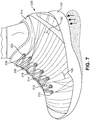
- FIG. 7 depicts the embodiment of shoe 200, as shown in FIG. 6 , as it flexes during use.
- the concept depicted in the illustrations of FIG. 4 above may be applied to a shoe in use as it flexes.
- the user's heel comes off the ground as the user strides.
- the rest of the shoe including the upper and sole structure, may flex.
- second flex zone 126 and third flex zone 130 may flex.
- the weld zones bordering each flex zone move closer together. This is shown in greater detail below in FIGS. 8, 9 , 12 and 13 .
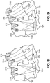
- FIG. 8 illustrates the concept of flexing described above in FIG. 4 .
- FIG. 8 depicts a portion of shoe 200 in an unflexed state, as shown in FIG. 6 .
- the illustrations focus on second unwelded flex zone 126.
- the illustration of FIG. 8 depicts this portion of shoe 200 when the shoe is at rest or in its unflexed position.
- Second unwelded flex zone 126 may be located between second weld zone 124 and third weld zone 128.
- Second unwelded flex zone 126 may continue from sole structure 140 through and between the lace eyelets. At rest, the distance between second weld zone 124 and third weld zone 128 at a specific distance from the sole structure in second unwelded zone 126 is indicated as spacing 210.
- the distance between second weld zone 124 and third weld zone 128 where each weld zone contacts or is fixed to the sole structure in second unwelded zone 126 is indicated as spacing 212.
- FIG. 9 depicts the same portion of shoe 200 shown in FIG. 8 . However, the illustration of FIG. 9 shows the portion of shoe 200 in a flexed state, as shown in FIG. 7 . Similar to FIG. 8 , the illustration of FIG. 9 depicts an embodiment of second unwelded flex zone 126 located between second weld zone 124 and third weld zone 128. Further, the distance between second weld zone 124 and third weld zone 128 at a specific distance from sole structure 140 in second unwelded zone 126 is indicated as spacing 220.
- FIG. 9 depicts the movement that takes places in second unwelded flex zone 126 during use.
- the unwelded flex zone When at rest, the unwelded flex zone may be in its original position ( FIG. 8 ). However, when in use and flexed, the unwelded flex zone may flex as sole structure 140 flexes.
- the distance between second weld zone 124 and third weld zone 128 at a specific distance from the sole structure in second unwelded zone 126 changes.
- spacing 220 may be substantially smaller than spacing 210.
- spacing 212 shown in both FIG. 8 and FIG. 9 ), which is a distance between second weld zone 124 and third weld zone 128 along sole structure 140, remains substantially the same in both the unflexed and flexed positions.
- the unwelded flex zone of the embodiment of the shoe upper may be selectively located on the upper to flex in a similar manner as the foot inside the shoe flexes.
- the eyelets may also be selectively located on the upper to allow the unwelded flex zone to flex unencumbered when the shoe flexes.
- a shoe upper having flex zones that mimic the flexing of the foot may provide a more comfortable shoe.
- a shoe upper having flex zones may limit excess movement of the foot relative to the sole structure and the upper.
- a shoe upper having flex zones may ensure that the foot remains properly positioned relative to the sole structure.
- FIGS. 10 and 11 show a portion of shoe 100 in a flexed and unflexed state.
- the illustrations again focus on second unwelded flex zone 126.
- the illustration of FIG. 10 depicts this portion of the shoe when the shoe is at rest or in its unflexed position, as shown in FIG. 1 .
- Second unwelded flex zone 126 may be located between second weld zone 124 and third weld zone 128.
- first eyelet portion 154 and second eyelet portion 152 are also shown.
- First eyelet portion 154 may be located adjacent to second weld zone 124.
- Second eyelet portion 152 may be located adjacent to third weld zone 128.
- Second unwelded flex zone 126 may continue between the weld zones from sole structure 140 through and between first eyelet portion 154 and second eyelet portion 152.
- the distance between first eyelet portion 154 and second eyelet portion 152 in second unwelded zone 126 is indicated as spacing 210.
- the distance between second weld zone 124 and third weld zone 128 where each weld zone contacts sole structure 140 in second unwelded zone 126 is indicated as spacing 212.
- FIG. 11 depicts the same portion of shoe 100 as is shown FIG. 10 .
- the illustration of FIG. 11 shows the portion of the shoe in a flexed state, as shown in FIG. 5 .
- the illustration of the right depicts an embodiment of second unwelded flex zone 126 located between second weld zone 124 and third weld zone 128.
- second unwelded flex zone 126 also is located between first eyelet portion 154 and second eyelet portion 152.
- the distance between first eyelet portion 154 and second eyelet portion 152 is indicated as spacing 220.
- the distance between second weld zone 124 and third weld zone 128 where each weld zone contacts sole structure 140 in second unwelded zone 126 is indicated as spacing 212.
- FIG. 11 depicts the movement that takes places in second unwelded flex zone 126 during use.
- the unwelded flex zone When at rest, the unwelded flex zone may be in its original position ( FIG. 10 ). However, when in use and flexed, second unwelded flex zone 126 may flex as sole structure 140 flexes.
- the distance between first eyelet portion 154 and second eyelet portion 152 changes.
- spacing 220 may be substantially smaller than spacing 210.
- spacing 212 shown in both FIG. 10 and FIG. 11 ), which is a distance between second weld zone 124 and third weld zone 128 along sole structure 140, remains substantially the same in both the unflexed and flexed positions.
- the unwelded flex zone of the embodiment of the shoe upper may be selectively located on the upper to flex in a similar manner as the foot inside the shoe flexes.
- the material surrounding the eyelets may also be selectively located on the upper to allow the unwelded flex zone to flex unencumbered when the shoe flexes.
- a shoe upper having flex zones that mimic the flexing of the foot may provide a more comfortable shoe.
- a shoe upper having flex zones may limit excess movement of the foot relative to the sole structure and the upper.
- a shoe upper having flex zones may ensure that the foot remains properly positioned relative to the sole structure.
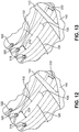
- FIGS. 12 and 13 depict another weld zone of shoe 200 in the flexed and unflexed state.
- the illustration of FIG. 12 depicts a portion of shoe 200 in its unflexed position, as shown in FIG. 6 .
- Third unwelded flex zone 130 may be located between third weld zone 128 and fourth weld zone 132.
- Third unwelded flex zone 130 may continue from sole structure 140 through and between the lace eyelets. At rest, the distance between third weld zone 128 and fourth weld zone 132 at a specific distance from the sole structure in third unwelded zone 130 is indicated as spacing 230.
- the distance between third weld zone 128 and fourth weld zone 132 in third unwelded zone 130 where each weld zone contacts sole structure 140 and heel support 142 is indicated as spacing 232.
- FIG. 13 depicts the same portion of shoe 200 shown in FIG. 12 . However, the illustration of FIG. 13 shows the same portion of shoe 200 in a flexed state, as shown in FIG. 7 . Similar to FIG. 12, FIG. 13 depicts an embodiment of third unwelded flex zone 130 located between third weld zone 128 and fourth weld zone 132. Further, the distance between third weld zone 128 and fourth weld zone 132 at a specific distance from the sole structure in third unwelded zone 130 is indicated as spacing 240.
- FIG. 13 depicts the movement that takes places in third unwelded flex zone 130 during use.
- third unwelded flex zone 130 may be in its original position ( FIG. 12 ).
- third unwelded flex zone 130 may flex as sole structure 140 flexes.
- spacing 240 may be substantially smaller than spacing 230.
- spacing 232 shown in both FIG. 12 and FIG. 13 ), which is a distance between third weld zone 128 and fourth weld zone 132 along sole structure 140, remains substantially the same in both the unflexed and flexed positions.
- the unwelded flex zone of the embodiment of a shoe upper may be selectively located on the upper to be configured to flex in a similar manner as the foot inside the shoe flexes.
- the eyelets may also be selectively located on the upper to allow the unwelded flex zone to flex unencumbered when the shoe flexes.
- a shoe upper having flex zones that mimic the flexing of the foot may provide a more comfortable shoe.
- a shoe upper having flex zones may limit excess movement of the foot relative to the sole structure and the upper.
- a shoe upper having flex zones may ensure that the foot remains properly positioned relative to the sole structure.
- FIGS. 14 and 15 illustrate another unwelded zone of the upper of shoe 100.
- the illustration of FIG. 14 depicts a portion of shoe 100 at rest or in its flexed position, as shown in FIG. 1 .
- Third unwelded flex zone 130 may be located between third weld zone 128 and fourth weld zone 132. Further, second eyelet portion 152 and third eyelet portion 150 are also shown. Second eyelet portion 152 may be located adjacent to third weld zone 128. Third eyelet portion 150 may be located adjacent to fourth weld zone 132.
- Third unwelded flex zone 130 may continue between the weld zones from sole structure 140 through and between second eyelet portion 152 and third eyelet portion 150.
- the distance between second eyelet portion 152 and third eyelet portion 150 in third unwelded zone 130 is indicated as spacing 230.
- the distance between third weld zone 128 and fourth weld zone 132 where the zones contact sole structure 140 and heel support 142 is indicated as spacing 232.
- FIG. 15 depicts the same portion of shoe 100 shown in FIG. 14 . However, the illustration of FIG. 15 shows the same portion of the shoe in a flexed state, as shown in FIG. 5 . Similar to FIG. 14, FIG. 15 depicts an embodiment of third unwelded flex zone 130 located between third weld zone 128 and fourth weld zone 132. Further, third unwelded flex zone 130 also is located between second eyelet portion 152 and third eyelet portion 150. Still further, the distance between second eyelet portion 152 and third eyelet portion 150 is indicated as spacing 240.
- FIG. 15 depicts the movement that takes places in third unwelded flex zone 130 during use.
- third unwelded flex zone 130 may be in its original position ( FIG. 14 ).
- third unwelded flex zone 130 may flex as sole structure 140 flexes.
- spacing 240 may be substantially smaller than spacing 230.
- spacing 232 shown in both FIG. 14 and FIG. 15 ), which is a distance between third weld zone 128 and fourth weld zone 132 along sole structure 140, remains substantially the same in both the unflexed and flexed positions.
- the unwelded flex zone of the embodiment of the shoe upper may be selectively located on the upper to flex in a similar manner as the foot inside the shoe flexes.
- the material surrounding the eyelets may also be selectively located on the upper to allow the unwelded flex zone to flex unencumbered.
- a shoe upper having flex zones that mimic the flexing of the foot may provide a more comfortable shoe.
- a shoe upper having flex zones may limit excess movement of the foot relative to the sole structure and the upper.
- a shoe upper having flex zones may ensure that the foot remains properly positioned relative to the sole structure.
- the upper portion of the shoe of this disclosure having multiple weld zones may have various configurations. Although each of these configurations are discussed separately, many of the concepts presented above may be combined to impart specific properties or otherwise ensure that upper having multiple weld zones may be optimized for a particular purpose or product.
Landscapes
- Chemical & Material Sciences (AREA)
- Engineering & Computer Science (AREA)
- Materials Engineering (AREA)
- Footwear And Its Accessory, Manufacturing Method And Apparatuses (AREA)
Claims (14)
- Schuhoberteil (114), umfassend:ein Basismaterial (112), umfassend:eine laterale Seite, die mehrere Schweißnahtzonen (120, 124, 128, 132), mehrere ungeschweißte flexible Zonen (122, 126, 130) und mehrere Ösenabschnitte (150, 152, 154; 310, 312, 314, 316, 318, 320, 322) aufweist, die auf dem Basismaterial (112) obenauf liegen; undeine mediale Seite, die mehrere Schweißnahtzonen (160, 164, 178), mehrere ungeschweißte flexible Zonen (162, 166) und mehrere Ösenabschnitte (172, 174, 176) aufweist, die auf dem Basismaterial (112) obenauf liegen;wobeijede Schweißnahtzone eine oder mehrere Schweißnähte umfasst,jede der Schweißnähte Bereiche umfasst, in denen die einzelnen Fasern, Drähte oder Fäden einer Schicht des Basismaterials (112) miteinander durch Schmelzen vereinigt oder verschmolzen sind,die ungeschweißten flexiblen Zonen (122, 126, 130, 162, 166) ausgestaltet sind, ungeschweißt zu bleiben,die laterale Seite des Schuhoberteils (114) eine erste Schweißnahtzone (120) aufweist, die sich in einem Vorderkappenabschnitt des Schuhoberteils (114) befindet,sich in der ersten Schweißnahtzone (120) eine Reihe von Schweißnähten radial über dem Vorderkappenabschnitt des Schuhoberteils (114) von der lateralen Seite bis zu der medialen Seite des Schuhoberteils (114) befindet,sich eine zweite Schweißnahtzone (124) entlang der lateralen Seite zwischen einem ersten Ösenabschnitt (154) und einem unteren Abschnitt des Schuhoberteils (114) befindet,sich eine erste ungeschweißte flexible Zone (122) in dem Vorderkappenabschnitt des Schuhoberteils (114) zwischen der ersten Schweißnahtzone (120) und der zweiten Schweißnahtzone (124) befindet,die erste ungeschweißte flexible Zone ausgestaltet ist, radial von dem unteren Abschnitt des Schuhoberteils (114) an der lateralen Seite des Schuhoberteils (114) bis zu der medialen Seite des Schuhoberteils (114) zu reichen, undsich die Ösenabschnitte (150, 152, 154, 172, 174, 176; 310, 312, 314, 316, 318, 320, 322) selektiv auf dem Schuhoberteil (114) befinden, um eine unbehinderte Flexibilität in den ungeschweißten flexiblen Zonen (122, 126, 130, 162, 166) zu ermöglichen.
- Schuhoberteil (114) nach Anspruch 1, wobei die laterale Seite des Schuhoberteils (114) die erste ungeschweißte flexible Zone (122), eine zweite ungeschweißte flexible Zone (126) und eine dritte ungeschweißte flexible Zone (130) umfasst.
- Schuhoberteil (114) nach Anspruch 1, wobei sich die zweite ungeschweißte flexible Zone (126) zwischen der zweiten Schweißnahtzone (124) und einer dritten Schweißnahtzone (128) befindet;
wobei sich die dritte Schweißnahtzone (128) entlang der lateralen Seite zwischen einem zweiten Ösenabschnitt (152) und dem unteren Abschnitt des Schuhoberteils (114) befindet; und
wobei sich die zweite ungeschweißte flexible Zone (126) überdies zwischen einem ersten Ösenabschnitt (154) und einem zweiten Ösenabschnitt (152) befindet. - Schuhoberteil (114) nach Anspruch 3, wobei sich die dritte ungeschweißte flexible Zone (130) zwischen der dritten Schweißnahtzone (128) und einer vierten Schweißnahtzone (132) befindet;
wobei sich die vierte Schweißnahtzone (132) von einem dritten Ösenabschnitt (150) um einen Knöchelabschnitt des Schuhoberteils (114) herum bis zu einer äußeren Fersenstütze (142) befindet; und
wobei sich die dritte ungeschweißte flexible Zone (130) überdies zwischen dem zweiten Ösenabschnitt (152) und dem dritten Ösenabschnitt (150) erstreckt. - Schuhoberteil (114) nach Anspruch 2, wobei die mediale Seite des Schuhoberteils (114) überdies eine vierte ungeschweißte flexible Zone (162) und eine fünfte ungeschweißte flexible Zone (166) umfasst.
- Schuhoberteil (114) nach Anspruch 5, wobei sich die vierte ungeschweißte flexible Zone (162) zwischen einer fünften Schweißnahtzone (160) und einer sechsten Schweißnahtzone (164) befindet;
wobei sich die fünfte Schweißnahtzone (160) zwischen einem vierten Ösenabschnitt (172) und dem unteren Abschnitt des Schuhoberteils (114) befindet;
wobei die Schweißnähte in der sechsten Schweißnahtzone (164) von einem fünften Ösenabschnitt (174) bis zu dem unteren Abschnitt des Schuhoberteils (114) gebildet sind; und
wobei sich die vierte ungeschweißte flexible Zone (162) überdies zwischen dem vierten Ösenabschnitt (172) und dem fünften Ösenabschnitt (174) befindet. - Schuhoberteil (114) nach Anspruch 6, wobei sich die fünfte ungeschweißte flexible Zone (166) zwischen der sechsten Schweißnahtzone (164) und einer siebten Schweißnahtzone (178) befindet;
wobei sich die siebte Schweißnahtzone (178) von einem sechsten Ösenabschnitt (176) um einen Knöchelabschnitt des Schuhoberteils (114) herum bis zu einer äußeren Fersenstütze (142) erstreckt; und
wobei sich die fünfte ungeschweißte flexible Zone (166) überdies zwischen dem fünften Ösenabschnitt (174) und dem sechsten Ösenabschnitt (176) befindet. - Schuh (100), umfassend:ein Oberteil (114) nach einem der vorhergehenden Ansprüche unddie Sohlenstruktur (140), die an dem Oberteil (114) angebracht ist.
- Schuh nach Anspruch 8, wobei die mehreren ungeschweißten flexiblen Zonen (122, 126, 130) an der lateralen Seite des Schuhoberteils (114) überdies eine erste ungeschweißte flexible Zone (122), eine zweite ungeschweißte flexible Zone (126) und eine dritte ungeschweißte flexible Zone (130) umfassen und die mehreren Schweißnahtzonen (120, 124, 128, 132) an der lateralen Seite eine erste Schweißnahtzone (120), eine zweite Schweißnahtzone (124), eine dritte Schweißnahtzone (128) und eine vierte Schweißnahtzone (132) umfassen;
das Oberteil (114) umfasst überdies einen Zehenriemen (144) und eine Zehenkappe (110), die auf dem Basismaterial (112) obenauf liegt und von der medialen Seite bis zu der lateralen Seite des Oberteils (114) reicht, und
wobei die erste ungeschweißte flexible Zone (122) radial von der lateralen Seite des Schuhs (100) zu der medialen Seite des Schuhs (100) zwischen der Zehenkappe (110) und den Schnürsenkeln reicht und Flexibilität zwischen der Zehenkappe (110) und einem Blatt des Schuhoberteils (114) ermöglicht. - Schuh nach Anspruch 9, wobei sich die zweite ungeschweißte flexible Zone (126) an der lateralen Seite des Oberteils (114) zwischen einer zweiten Schweißnahtzone (124) und einer dritten Schweißnahtzone (128) erstreckt; und wobei sich die zweite ungeschweißte flexible Zone (126) überdies von der Sohlenstruktur (140) gesehen durch und zwischen einem ersten Ösenabschnitt (154) und einem zweiten Ösenabschnitt (152) erstreckt.
- Schuh nach Anspruch 10, wobei die mehreren ungeschweißten flexiblen Zonen (162, 166) an der medialen Seite des Schuhoberteils (114) überdies eine vierte ungeschweißte flexible Zone (162) und eine fünfte ungeschweißte flexible Zone (166) umfassen und die mehreren Schweißnahtzonen (160, 164, 178) an der medialen Seite eine fünfte Schweißnahtzone (160), eine sechste Schweißnahtzone (164) und eine siebte Schweißnahtzone (178) umfassen;
wobei sich die vierte ungeschweißte flexible Zone (162) an der medialen Seite des Oberteils (114) zwischen der fünften Schweißnahtzone (160) und der sechsten Schweißnahtzone (164) befindet; und wobei sich die vierte ungeschweißte flexible Zone (162) von der Sohlenstruktur (140) durch und zwischen einem vierten Ösenabschnitt (172) und einem fünften Ösenabschnitt (174) erstreckt; und
wo die zweite ungeschweißte flexible Zone (126) an der lateralen Seite des Oberteils (114) der vierten ungeschweißten flexiblen Zone (162) an der medialen Seite des Oberteils (114) entspricht. - Schuh nach Anspruch 11, wobei sich die dritte ungeschweißte flexible Zone (130) an der lateralen Seite des Oberteils (114) zwischen der dritten Schweißnahtzone (128) und der vierten Schweißnahtzone (132) befindet; und wobei sich die dritte ungeschweißte flexible Zone (130) von der Sohlenstruktur (140) durch und zwischen dem zweiten Ösenabschnitt (152) und einem dritten Ösenabschnitt (150) erstreckt.
- Schuh nach Anspruch 12, wobei sich die fünfte ungeschweißte flexible Zone (166) an der medialen Seite des Oberteils (114) zwischen der sechsten Schweißnahtzone (164) und der siebten Schweißnahtzone (178) befindet; und wobei sich die fünfte ungeschweißte flexible Zone (166) von der Sohlenstruktur (140) durch und zwischen dem fünften Ösenabschnitt (174) und einem sechsten Ösenabschnitt (176) erstreckt; und
die dritte ungeschweißte flexible Zone (130) an der lateralen Seite des Oberteils (114) der fünften ungeschweißten flexiblen Zone (166) an der medialen Seite des Oberteils (114) entspricht. - Schuh nach Anspruch 8, wobei das Oberteil (114) überdies Folgendes umfasst:einen Zehenriemen (144);eine Zehenkappe (110), die auf dem Basismaterial (112) obenauf liegt, das von der medialen Seite zu der lateralen Seite des Oberteils (114) reicht; undeine äußere Fersenstütze (142), die auf dem Basismaterial (112) obenauf liegt, das von der medialen Seite zu der lateralen Seite des Oberteils (114) reicht.
Applications Claiming Priority (2)
| Application Number | Priority Date | Filing Date | Title |
|---|---|---|---|
| US13/766,081 US9237779B2 (en) | 2013-02-13 | 2013-02-13 | Shoe upper having multiple unwelded flex zones |
| PCT/US2014/015904 WO2014126947A2 (en) | 2013-02-13 | 2014-02-12 | Shoe upper having multiple unwelded flex zones |
Publications (2)
| Publication Number | Publication Date |
|---|---|
| EP2919610A2 EP2919610A2 (de) | 2015-09-23 |
| EP2919610B1 true EP2919610B1 (de) | 2018-12-12 |
Family
ID=50346087
Family Applications (1)
| Application Number | Title | Priority Date | Filing Date |
|---|---|---|---|
| EP14712063.8A Active EP2919610B1 (de) | 2013-02-13 | 2014-02-12 | Schuhoberteil mit mehreren ungeschweissten flexiblen zonen |
Country Status (4)
| Country | Link |
|---|---|
| US (1) | US9237779B2 (de) |
| EP (1) | EP2919610B1 (de) |
| CN (1) | CN105188449B (de) |
| WO (1) | WO2014126947A2 (de) |
Families Citing this family (14)
| Publication number | Priority date | Publication date | Assignee | Title |
|---|---|---|---|---|
| US9788608B2 (en) | 2013-02-13 | 2017-10-17 | Nike, Inc. | Shoe upper having multiple weld zones |
| US9687042B2 (en) * | 2013-08-07 | 2017-06-27 | Nike, Inc. | Article of footwear with a midsole structure |
| US10219580B2 (en) * | 2015-01-29 | 2019-03-05 | Nike, Inc. | Lace engaging structures and other features for articles of footwear and other foot-receiving devices |
| US20160242500A1 (en) * | 2015-02-20 | 2016-08-25 | Nike, Inc. | Wrestling shoe with textile on toe cap |
| US9687045B2 (en) * | 2015-02-27 | 2017-06-27 | Reebok International Limited | Article of footwear having an upper with inflation system |
| EP3981281B1 (de) | 2016-11-09 | 2024-03-27 | NIKE Innovate C.V. | Artikel, der ein aufgeschmolzenes material und ein gedrucktes element enthält, und sein herstellungsverfahren |
| US10499707B2 (en) | 2017-10-18 | 2019-12-10 | Reebok International Limited | Articles of footwear having a leno woven upper with a bladder component |
| US10834998B2 (en) * | 2018-04-13 | 2020-11-17 | Wolverine Outdoors, Inc. | Footwear including a holding cage |
| USD882233S1 (en) * | 2018-07-10 | 2020-04-28 | Nike, Inc. | Shoe |
| WO2021071892A1 (en) | 2019-10-08 | 2021-04-15 | All Star C.V. | Multi-layer textile |
| USD1010294S1 (en) * | 2020-07-14 | 2024-01-09 | Reebok International Limited | Shoe |
| USD958512S1 (en) * | 2020-10-09 | 2022-07-26 | Wolverine Outdoors, Inc. | Footwear upper |
| US12310457B2 (en) * | 2020-10-09 | 2025-05-27 | Nike, Inc. | Upper for article of footwear |
| US12702186B1 (en) | 2024-11-05 | 2026-08-11 | Richard Blood | Footwear with enhanced gripping system |
Family Cites Families (44)
| Publication number | Priority date | Publication date | Assignee | Title |
|---|---|---|---|---|
| US2994322A (en) | 1959-01-12 | 1961-08-01 | Charles C Cullen | Protective supporter |
| IT8121560U1 (it) * | 1981-04-23 | 1982-10-23 | Nuova Zarine S P A Costruzione Macch E Stampi Per Calzature | Calzatura con tomaia zonalmente ricoperta da materiale sintetico iniettato stabilmente unito alla tela |
| CA2084080C (en) | 1990-05-30 | 2000-01-11 | Eric D. Cohen | Athletic shoe having inflatable bladder |
| US5785806A (en) | 1996-07-22 | 1998-07-28 | Eastman Kodak Company | Ultrasonic cutting apparatus |
| US5894983A (en) | 1997-01-09 | 1999-04-20 | Harris Corporation | High frequency, low temperature thermosonic ribbon bonding process for system-level applications |
| US5713399A (en) | 1997-02-07 | 1998-02-03 | Albany International Corp. | Ultrasonic seaming of abutting strips for paper machine clothing |
| JPH10229620A (ja) | 1997-02-14 | 1998-08-25 | Yazaki Corp | 布線回路体の製造方法及び製造装置 |
| US5783008A (en) | 1997-03-31 | 1998-07-21 | Ford Global Technologies, Inc. | Apparatus and method for embedding conductors in a non-planar substrate |
| DE19825636C2 (de) | 1998-06-09 | 2000-07-20 | Freudenberg Carl Fa | Verfahren zur Faltenbildung bei Filtern |
| AU4849899A (en) | 1998-06-30 | 2000-01-17 | Trustees Of Tufts College | Multiple-material prototyping by ultrasonic adhesion |
| JP3704253B2 (ja) | 1999-05-28 | 2005-10-12 | 株式会社新川 | ボンディング装置の超音波トランスデューサ及びその製造方法 |
| US6519500B1 (en) | 1999-09-16 | 2003-02-11 | Solidica, Inc. | Ultrasonic object consolidation |
| US6382494B1 (en) | 2000-05-12 | 2002-05-07 | West Bond, Inc. | Automatic ultrasonic bonding machine with vertically tiered orthogonally translatable tool support platforms |
| WO2002043960A1 (en) | 2000-12-01 | 2002-06-06 | Stanhope Products Company | Improved ultrasonic weld pattern for adsorbent containing package |
| US6520399B1 (en) | 2001-09-14 | 2003-02-18 | Raytheon Company | Thermosonic bonding apparatus, tool, and method |
| US20030148076A1 (en) | 2002-02-01 | 2003-08-07 | Hsi-Ming Huang | Composite fabric for shoes |
| US6910288B2 (en) | 2002-12-18 | 2005-06-28 | Nike, Inc. | Footwear incorporating a textile with fusible filaments and fibers |
| JP4323852B2 (ja) | 2003-04-11 | 2009-09-02 | キヤノン株式会社 | トナー補給容器の製造方法 |
| US7424783B2 (en) * | 2003-06-30 | 2008-09-16 | Nike, Inc. | Article of apparel incorporating a stratified material |
| ITTO20030111U1 (it) | 2003-07-10 | 2005-01-11 | Diadora Invicta S P A | Calzatura con tomaia imbottita |
| US7883594B2 (en) | 2003-10-15 | 2011-02-08 | Ultrafab, Inc. | Wrapped pile weatherstripping and methods of making same |
| US7793434B2 (en) | 2004-09-03 | 2010-09-14 | Nike, Inc. | Article of footwear having an upper with a structured intermediate layer |
| US7493191B1 (en) | 2004-12-09 | 2009-02-17 | Miller Charles F | Auxiliary control apparatus for micro-manipulators used in ultrasonic bonding machines |
| CA2591552C (en) | 2004-12-17 | 2012-03-06 | Ultrafab, Inc. | Apparatus and method for making articles having filamentary material |
| US9598861B2 (en) | 2005-02-18 | 2017-03-21 | George Kalogridis Davis | Fire-resistant ultra-lightweight panel with three-dimensional surface design |
| JP2006304862A (ja) | 2005-04-26 | 2006-11-09 | Toyo Tire & Rubber Co Ltd | クッションパッドの製造方法 |
| EP1910012B1 (de) | 2005-07-20 | 2018-05-30 | SCA Hygiene Products AB | Anordnung und verfahren zur behandlung eines materials mittels einer ultraschallvorrichtung |
| US7637032B2 (en) | 2005-07-29 | 2009-12-29 | Nike, Inc. | Footwear structure with textile upper member |
| US20070270969A1 (en) | 2006-05-17 | 2007-11-22 | Schmid Steven R | Welded-woven materials |
| US20070295440A1 (en) | 2006-05-24 | 2007-12-27 | Stucker Brent E | Surface roughness reduction for improving bonding in ultrasonic consolidation rapid manufacturing |
| US8312646B2 (en) | 2006-05-25 | 2012-11-20 | Nike, Inc. | Article of footwear incorporating a tensile element |
| WO2008013499A1 (en) | 2006-07-28 | 2008-01-31 | Chromogenics Sweden Ab | Manufacturing of electrochromic devices |
| US20080028640A1 (en) * | 2006-08-01 | 2008-02-07 | David Lacorazza | Athletic shoe having a segmented upper |
| US8122616B2 (en) | 2008-07-25 | 2012-02-28 | Nike, Inc. | Composite element with a polymer connecting layer |
| US8215033B2 (en) | 2009-04-16 | 2012-07-10 | Nike, Inc. | Article of footwear for snowboarding |
| WO2011004422A1 (ja) | 2009-07-06 | 2011-01-13 | 株式会社アシックス | 紐締めフィッティング構造を備えた靴 |
| US8321984B2 (en) | 2009-10-21 | 2012-12-04 | Nike, Inc. | Composite shoe upper and method of making same |
| CN101774077A (zh) | 2010-03-19 | 2010-07-14 | 周志坚 | 数控旋转型三维超声波金丝球焊机 |
| DE102010017665A1 (de) | 2010-06-30 | 2012-01-05 | Deeluxe Sportartikel Handels Gmbh | Stiefel, insbesondere Ski- oder Snowboardstiefel |
| DE102010017766B4 (de) * | 2010-07-06 | 2013-11-14 | Ford Global Technologies, Llc. | Kühlanordnung für Brennkraftmaschinen |
| US8973288B2 (en) | 2010-07-30 | 2015-03-10 | Nike, Inc. | Footwear incorporating angled tensile strand elements |
| US8800172B2 (en) | 2011-04-04 | 2014-08-12 | Nike, Inc. | Article of footwear having a knit upper with a polymer layer |
| US8844167B2 (en) | 2011-07-18 | 2014-09-30 | Nike, Inc. | Article of footwear having an upper with cord elements |
| US9872535B2 (en) | 2012-12-20 | 2018-01-23 | Nike, Inc. | Article of footwear with a harness and fluid-filled chamber arrangement |
-
2013
- 2013-02-13 US US13/766,081 patent/US9237779B2/en active Active
-
2014
- 2014-02-12 EP EP14712063.8A patent/EP2919610B1/de active Active
- 2014-02-12 CN CN201480008442.9A patent/CN105188449B/zh active Active
- 2014-02-12 WO PCT/US2014/015904 patent/WO2014126947A2/en not_active Ceased
Non-Patent Citations (1)
| Title |
|---|
| None * |
Also Published As
| Publication number | Publication date |
|---|---|
| CN105188449B (zh) | 2018-01-16 |
| EP2919610A2 (de) | 2015-09-23 |
| US20140223771A1 (en) | 2014-08-14 |
| CN105188449A (zh) | 2015-12-23 |
| WO2014126947A3 (en) | 2014-10-16 |
| WO2014126947A2 (en) | 2014-08-21 |
| US9237779B2 (en) | 2016-01-19 |
Similar Documents
| Publication | Publication Date | Title |
|---|---|---|
| US12527380B2 (en) | Shoe upper having multiple weld zones | |
| US9237779B2 (en) | Shoe upper having multiple unwelded flex zones | |
| EP2919607B1 (de) | Schuhwerk mit einer gestrickten komponente | |
| US9132601B2 (en) | Spacer textile material with tensile strands having multiple entry and exit points | |
| WO2017044318A1 (en) | Article off footwear with knitted component having plurality of graduated projections | |
| HK1209986B (en) | Article of footwear incorporating a knitted component | |
| HK1205438B (en) | Article of footwear incorporating a knitted component | |
| HK1205439B (en) | Article of footwear incorporating a knitted component | |
| HK1205440B (en) | Article of footwear incorporating a knitted component |
Legal Events
| Date | Code | Title | Description |
|---|---|---|---|
| PUAI | Public reference made under article 153(3) epc to a published international application that has entered the european phase |
Free format text: ORIGINAL CODE: 0009012 |
|
| 17P | Request for examination filed |
Effective date: 20150618 |
|
| AK | Designated contracting states |
Kind code of ref document: A2 Designated state(s): AL AT BE BG CH CY CZ DE DK EE ES FI FR GB GR HR HU IE IS IT LI LT LU LV MC MK MT NL NO PL PT RO RS SE SI SK SM TR |
|
| AX | Request for extension of the european patent |
Extension state: BA ME |
|
| DAX | Request for extension of the european patent (deleted) | ||
| STAA | Information on the status of an ep patent application or granted ep patent |
Free format text: STATUS: EXAMINATION IS IN PROGRESS |
|
| 17Q | First examination report despatched |
Effective date: 20170321 |
|
| GRAP | Despatch of communication of intention to grant a patent |
Free format text: ORIGINAL CODE: EPIDOSNIGR1 |
|
| STAA | Information on the status of an ep patent application or granted ep patent |
Free format text: STATUS: GRANT OF PATENT IS INTENDED |
|
| INTG | Intention to grant announced |
Effective date: 20180704 |
|
| RAP1 | Party data changed (applicant data changed or rights of an application transferred) |
Owner name: NIKE INNOVATE C.V. |
|
| GRAS | Grant fee paid |
Free format text: ORIGINAL CODE: EPIDOSNIGR3 |
|
| GRAA | (expected) grant |
Free format text: ORIGINAL CODE: 0009210 |
|
| STAA | Information on the status of an ep patent application or granted ep patent |
Free format text: STATUS: THE PATENT HAS BEEN GRANTED |
|
| AK | Designated contracting states |
Kind code of ref document: B1 Designated state(s): AL AT BE BG CH CY CZ DE DK EE ES FI FR GB GR HR HU IE IS IT LI LT LU LV MC MK MT NL NO PL PT RO RS SE SI SK SM TR |
|
| REG | Reference to a national code |
Ref country code: GB Ref legal event code: FG4D |
|
| REG | Reference to a national code |
Ref country code: CH Ref legal event code: EP |
|
| REG | Reference to a national code |
Ref country code: AT Ref legal event code: REF Ref document number: 1074847 Country of ref document: AT Kind code of ref document: T Effective date: 20181215 |
|
| REG | Reference to a national code |
Ref country code: DE Ref legal event code: R096 Ref document number: 602014037796 Country of ref document: DE |
|
| REG | Reference to a national code |
Ref country code: IE Ref legal event code: FG4D |
|
| REG | Reference to a national code |
Ref country code: NL Ref legal event code: MP Effective date: 20181212 |
|
| REG | Reference to a national code |
Ref country code: LT Ref legal event code: MG4D |
|
| PG25 | Lapsed in a contracting state [announced via postgrant information from national office to epo] |
Ref country code: ES Free format text: LAPSE BECAUSE OF FAILURE TO SUBMIT A TRANSLATION OF THE DESCRIPTION OR TO PAY THE FEE WITHIN THE PRESCRIBED TIME-LIMIT Effective date: 20181212 Ref country code: LV Free format text: LAPSE BECAUSE OF FAILURE TO SUBMIT A TRANSLATION OF THE DESCRIPTION OR TO PAY THE FEE WITHIN THE PRESCRIBED TIME-LIMIT Effective date: 20181212 Ref country code: BG Free format text: LAPSE BECAUSE OF FAILURE TO SUBMIT A TRANSLATION OF THE DESCRIPTION OR TO PAY THE FEE WITHIN THE PRESCRIBED TIME-LIMIT Effective date: 20190312 Ref country code: HR Free format text: LAPSE BECAUSE OF FAILURE TO SUBMIT A TRANSLATION OF THE DESCRIPTION OR TO PAY THE FEE WITHIN THE PRESCRIBED TIME-LIMIT Effective date: 20181212 Ref country code: NO Free format text: LAPSE BECAUSE OF FAILURE TO SUBMIT A TRANSLATION OF THE DESCRIPTION OR TO PAY THE FEE WITHIN THE PRESCRIBED TIME-LIMIT Effective date: 20190312 Ref country code: LT Free format text: LAPSE BECAUSE OF FAILURE TO SUBMIT A TRANSLATION OF THE DESCRIPTION OR TO PAY THE FEE WITHIN THE PRESCRIBED TIME-LIMIT Effective date: 20181212 Ref country code: FI Free format text: LAPSE BECAUSE OF FAILURE TO SUBMIT A TRANSLATION OF THE DESCRIPTION OR TO PAY THE FEE WITHIN THE PRESCRIBED TIME-LIMIT Effective date: 20181212 |
|
| REG | Reference to a national code |
Ref country code: AT Ref legal event code: MK05 Ref document number: 1074847 Country of ref document: AT Kind code of ref document: T Effective date: 20181212 |
|
| PG25 | Lapsed in a contracting state [announced via postgrant information from national office to epo] |
Ref country code: SE Free format text: LAPSE BECAUSE OF FAILURE TO SUBMIT A TRANSLATION OF THE DESCRIPTION OR TO PAY THE FEE WITHIN THE PRESCRIBED TIME-LIMIT Effective date: 20181212 Ref country code: AL Free format text: LAPSE BECAUSE OF FAILURE TO SUBMIT A TRANSLATION OF THE DESCRIPTION OR TO PAY THE FEE WITHIN THE PRESCRIBED TIME-LIMIT Effective date: 20181212 Ref country code: RS Free format text: LAPSE BECAUSE OF FAILURE TO SUBMIT A TRANSLATION OF THE DESCRIPTION OR TO PAY THE FEE WITHIN THE PRESCRIBED TIME-LIMIT Effective date: 20181212 Ref country code: GR Free format text: LAPSE BECAUSE OF FAILURE TO SUBMIT A TRANSLATION OF THE DESCRIPTION OR TO PAY THE FEE WITHIN THE PRESCRIBED TIME-LIMIT Effective date: 20190313 |
|
| PG25 | Lapsed in a contracting state [announced via postgrant information from national office to epo] |
Ref country code: NL Free format text: LAPSE BECAUSE OF FAILURE TO SUBMIT A TRANSLATION OF THE DESCRIPTION OR TO PAY THE FEE WITHIN THE PRESCRIBED TIME-LIMIT Effective date: 20181212 |
|
| PG25 | Lapsed in a contracting state [announced via postgrant information from national office to epo] |
Ref country code: PT Free format text: LAPSE BECAUSE OF FAILURE TO SUBMIT A TRANSLATION OF THE DESCRIPTION OR TO PAY THE FEE WITHIN THE PRESCRIBED TIME-LIMIT Effective date: 20190412 Ref country code: CZ Free format text: LAPSE BECAUSE OF FAILURE TO SUBMIT A TRANSLATION OF THE DESCRIPTION OR TO PAY THE FEE WITHIN THE PRESCRIBED TIME-LIMIT Effective date: 20181212 Ref country code: IT Free format text: LAPSE BECAUSE OF FAILURE TO SUBMIT A TRANSLATION OF THE DESCRIPTION OR TO PAY THE FEE WITHIN THE PRESCRIBED TIME-LIMIT Effective date: 20181212 Ref country code: PL Free format text: LAPSE BECAUSE OF FAILURE TO SUBMIT A TRANSLATION OF THE DESCRIPTION OR TO PAY THE FEE WITHIN THE PRESCRIBED TIME-LIMIT Effective date: 20181212 |
|
| PG25 | Lapsed in a contracting state [announced via postgrant information from national office to epo] |
Ref country code: SM Free format text: LAPSE BECAUSE OF FAILURE TO SUBMIT A TRANSLATION OF THE DESCRIPTION OR TO PAY THE FEE WITHIN THE PRESCRIBED TIME-LIMIT Effective date: 20181212 Ref country code: EE Free format text: LAPSE BECAUSE OF FAILURE TO SUBMIT A TRANSLATION OF THE DESCRIPTION OR TO PAY THE FEE WITHIN THE PRESCRIBED TIME-LIMIT Effective date: 20181212 Ref country code: SK Free format text: LAPSE BECAUSE OF FAILURE TO SUBMIT A TRANSLATION OF THE DESCRIPTION OR TO PAY THE FEE WITHIN THE PRESCRIBED TIME-LIMIT Effective date: 20181212 Ref country code: RO Free format text: LAPSE BECAUSE OF FAILURE TO SUBMIT A TRANSLATION OF THE DESCRIPTION OR TO PAY THE FEE WITHIN THE PRESCRIBED TIME-LIMIT Effective date: 20181212 Ref country code: IS Free format text: LAPSE BECAUSE OF FAILURE TO SUBMIT A TRANSLATION OF THE DESCRIPTION OR TO PAY THE FEE WITHIN THE PRESCRIBED TIME-LIMIT Effective date: 20190412 |
|
| REG | Reference to a national code |
Ref country code: DE Ref legal event code: R097 Ref document number: 602014037796 Country of ref document: DE |
|
| REG | Reference to a national code |
Ref country code: CH Ref legal event code: PL |
|
| PLBE | No opposition filed within time limit |
Free format text: ORIGINAL CODE: 0009261 |
|
| STAA | Information on the status of an ep patent application or granted ep patent |
Free format text: STATUS: NO OPPOSITION FILED WITHIN TIME LIMIT |
|
| PG25 | Lapsed in a contracting state [announced via postgrant information from national office to epo] |
Ref country code: SI Free format text: LAPSE BECAUSE OF FAILURE TO SUBMIT A TRANSLATION OF THE DESCRIPTION OR TO PAY THE FEE WITHIN THE PRESCRIBED TIME-LIMIT Effective date: 20181212 Ref country code: MC Free format text: LAPSE BECAUSE OF FAILURE TO SUBMIT A TRANSLATION OF THE DESCRIPTION OR TO PAY THE FEE WITHIN THE PRESCRIBED TIME-LIMIT Effective date: 20181212 Ref country code: AT Free format text: LAPSE BECAUSE OF FAILURE TO SUBMIT A TRANSLATION OF THE DESCRIPTION OR TO PAY THE FEE WITHIN THE PRESCRIBED TIME-LIMIT Effective date: 20181212 Ref country code: LU Free format text: LAPSE BECAUSE OF NON-PAYMENT OF DUE FEES Effective date: 20190212 Ref country code: DK Free format text: LAPSE BECAUSE OF FAILURE TO SUBMIT A TRANSLATION OF THE DESCRIPTION OR TO PAY THE FEE WITHIN THE PRESCRIBED TIME-LIMIT Effective date: 20181212 |
|
| 26N | No opposition filed |
Effective date: 20190913 |
|
| REG | Reference to a national code |
Ref country code: BE Ref legal event code: MM Effective date: 20190228 |
|
| REG | Reference to a national code |
Ref country code: IE Ref legal event code: MM4A |
|
| PG25 | Lapsed in a contracting state [announced via postgrant information from national office to epo] |
Ref country code: LI Free format text: LAPSE BECAUSE OF NON-PAYMENT OF DUE FEES Effective date: 20190228 Ref country code: CH Free format text: LAPSE BECAUSE OF NON-PAYMENT OF DUE FEES Effective date: 20190228 |
|
| PG25 | Lapsed in a contracting state [announced via postgrant information from national office to epo] |
Ref country code: IE Free format text: LAPSE BECAUSE OF NON-PAYMENT OF DUE FEES Effective date: 20190212 |
|
| PG25 | Lapsed in a contracting state [announced via postgrant information from national office to epo] |
Ref country code: BE Free format text: LAPSE BECAUSE OF NON-PAYMENT OF DUE FEES Effective date: 20190228 |
|
| PG25 | Lapsed in a contracting state [announced via postgrant information from national office to epo] |
Ref country code: TR Free format text: LAPSE BECAUSE OF FAILURE TO SUBMIT A TRANSLATION OF THE DESCRIPTION OR TO PAY THE FEE WITHIN THE PRESCRIBED TIME-LIMIT Effective date: 20181212 |
|
| PG25 | Lapsed in a contracting state [announced via postgrant information from national office to epo] |
Ref country code: MT Free format text: LAPSE BECAUSE OF NON-PAYMENT OF DUE FEES Effective date: 20190212 |
|
| PG25 | Lapsed in a contracting state [announced via postgrant information from national office to epo] |
Ref country code: CY Free format text: LAPSE BECAUSE OF FAILURE TO SUBMIT A TRANSLATION OF THE DESCRIPTION OR TO PAY THE FEE WITHIN THE PRESCRIBED TIME-LIMIT Effective date: 20181212 |
|
| PG25 | Lapsed in a contracting state [announced via postgrant information from national office to epo] |
Ref country code: HU Free format text: LAPSE BECAUSE OF FAILURE TO SUBMIT A TRANSLATION OF THE DESCRIPTION OR TO PAY THE FEE WITHIN THE PRESCRIBED TIME-LIMIT; INVALID AB INITIO Effective date: 20140212 |
|
| PG25 | Lapsed in a contracting state [announced via postgrant information from national office to epo] |
Ref country code: MK Free format text: LAPSE BECAUSE OF FAILURE TO SUBMIT A TRANSLATION OF THE DESCRIPTION OR TO PAY THE FEE WITHIN THE PRESCRIBED TIME-LIMIT Effective date: 20181212 |
|
| P01 | Opt-out of the competence of the unified patent court (upc) registered |
Effective date: 20230515 |
|
| PGFP | Annual fee paid to national office [announced via postgrant information from national office to epo] |
Ref country code: FR Payment date: 20251208 Year of fee payment: 13 |
|
| PGFP | Annual fee paid to national office [announced via postgrant information from national office to epo] |
Ref country code: GB Payment date: 20260106 Year of fee payment: 13 |
|
| PGFP | Annual fee paid to national office [announced via postgrant information from national office to epo] |
Ref country code: DE Payment date: 20251216 Year of fee payment: 13 |